EP3907251A1 - Plaquettes solides utilisées en tant qu'agent de remplissage dans une résine thermodurcie durcissable par uv pour améliorer l'isolation électrique de barres conductrices de haute tension - Google Patents
Plaquettes solides utilisées en tant qu'agent de remplissage dans une résine thermodurcie durcissable par uv pour améliorer l'isolation électrique de barres conductrices de haute tension Download PDFInfo
- Publication number
- EP3907251A1 EP3907251A1 EP20173534.7A EP20173534A EP3907251A1 EP 3907251 A1 EP3907251 A1 EP 3907251A1 EP 20173534 A EP20173534 A EP 20173534A EP 3907251 A1 EP3907251 A1 EP 3907251A1
- Authority
- EP
- European Patent Office
- Prior art keywords
- mixture
- conductor
- electrical insulation
- platelets
- mica
- Prior art date
- Legal status (The legal status is an assumption and is not a legal conclusion. Google has not performed a legal analysis and makes no representation as to the accuracy of the status listed.)
- Pending
Links
Images

Classifications
-
- H—ELECTRICITY
- H01—ELECTRIC ELEMENTS
- H01B—CABLES; CONDUCTORS; INSULATORS; SELECTION OF MATERIALS FOR THEIR CONDUCTIVE, INSULATING OR DIELECTRIC PROPERTIES
- H01B3/00—Insulators or insulating bodies characterised by the insulating materials; Selection of materials for their insulating or dielectric properties
- H01B3/02—Insulators or insulating bodies characterised by the insulating materials; Selection of materials for their insulating or dielectric properties mainly consisting of inorganic substances
- H01B3/04—Insulators or insulating bodies characterised by the insulating materials; Selection of materials for their insulating or dielectric properties mainly consisting of inorganic substances mica
-
- C—CHEMISTRY; METALLURGY
- C08—ORGANIC MACROMOLECULAR COMPOUNDS; THEIR PREPARATION OR CHEMICAL WORKING-UP; COMPOSITIONS BASED THEREON
- C08K—Use of inorganic or non-macromolecular organic substances as compounding ingredients
- C08K3/00—Use of inorganic substances as compounding ingredients
- C08K3/34—Silicon-containing compounds
-
- C—CHEMISTRY; METALLURGY
- C08—ORGANIC MACROMOLECULAR COMPOUNDS; THEIR PREPARATION OR CHEMICAL WORKING-UP; COMPOSITIONS BASED THEREON
- C08K—Use of inorganic or non-macromolecular organic substances as compounding ingredients
- C08K3/00—Use of inorganic substances as compounding ingredients
- C08K3/34—Silicon-containing compounds
- C08K3/346—Clay
-
- C—CHEMISTRY; METALLURGY
- C08—ORGANIC MACROMOLECULAR COMPOUNDS; THEIR PREPARATION OR CHEMICAL WORKING-UP; COMPOSITIONS BASED THEREON
- C08K—Use of inorganic or non-macromolecular organic substances as compounding ingredients
- C08K7/00—Use of ingredients characterised by shape
-
- H—ELECTRICITY
- H01—ELECTRIC ELEMENTS
- H01B—CABLES; CONDUCTORS; INSULATORS; SELECTION OF MATERIALS FOR THEIR CONDUCTIVE, INSULATING OR DIELECTRIC PROPERTIES
- H01B17/00—Insulators or insulating bodies characterised by their form
- H01B17/56—Insulating bodies
- H01B17/62—Insulating-layers or insulating-films on metal bodies
-
- H—ELECTRICITY
- H01—ELECTRIC ELEMENTS
- H01B—CABLES; CONDUCTORS; INSULATORS; SELECTION OF MATERIALS FOR THEIR CONDUCTIVE, INSULATING OR DIELECTRIC PROPERTIES
- H01B3/00—Insulators or insulating bodies characterised by the insulating materials; Selection of materials for their insulating or dielectric properties
- H01B3/18—Insulators or insulating bodies characterised by the insulating materials; Selection of materials for their insulating or dielectric properties mainly consisting of organic substances
- H01B3/30—Insulators or insulating bodies characterised by the insulating materials; Selection of materials for their insulating or dielectric properties mainly consisting of organic substances plastics; resins; waxes
- H01B3/40—Insulators or insulating bodies characterised by the insulating materials; Selection of materials for their insulating or dielectric properties mainly consisting of organic substances plastics; resins; waxes epoxy resins
-
- H—ELECTRICITY
- H02—GENERATION; CONVERSION OR DISTRIBUTION OF ELECTRIC POWER
- H02K—DYNAMO-ELECTRIC MACHINES
- H02K3/00—Details of windings
- H02K3/30—Windings characterised by the insulating material
-
- H—ELECTRICITY
- H02—GENERATION; CONVERSION OR DISTRIBUTION OF ELECTRIC POWER
- H02K—DYNAMO-ELECTRIC MACHINES
- H02K3/00—Details of windings
- H02K3/32—Windings characterised by the shape, form or construction of the insulation
- H02K3/40—Windings characterised by the shape, form or construction of the insulation for high voltage, e.g. affording protection against corona discharges
Definitions
- Embodiments of the present disclosure relate generally to a UV curable mixture for forming an electrical insulation layer of a conductor.
- the electrical conductor may be for example a Roebel bar formed by a plurality of conductor strands and the insulation may avoid a short circuit between different strands of the Roebel bar.
- a Roebel bar arrangement formed by a plurality of reciprocally insulated conductor strands may for example reduce an overall electric resistance when compared to a conductor of the same section formed by only one conductor strand, i.e. a single wire.
- the electrical conductor for example the Roebel bar, also needs to be insulated electrically from the ground and/or from other conductors. A groundwall insulation is therefore needed.
- a coil wire, a stator winding, etc. different windings and/or coil turns need to be reciprocally insulated and to be insulated from bodies at ground potential and/or from other conductors.
- the electrical conductor may for example be a coil formed by one or more wires forming one or more windings, typically a plurality of windings. It is necessary to prevent a short circuit between different windings and/or between different portions of the electric conductor in order to ensure a uniform current flow along the whole conductor, for example to maximize a magnetic field induced by a current flowing in the conductor. Therefore for example different windings need to be reciprocally insulated.
- the electrical conductor may be part of a stator winding.
- electrical conductors may need an insulation to ensure safety, for example avoiding the risk of short circuits and/or electrocution to humans and/or animals.
- mica tapes and/or resin impregnation are used to form an electrical insulation.
- the resin impregnation may include a curing process.
- mica tapes and/or curing the resin to form an electric insulation is time and energy consuming and may lead to the formation of voids that lead to a non-uniform insulation of the electrical conductor.
- the use of mica tapes and/or the use of a curable resin for a resign impregnation may lead to a nonhomogeneous insulation, for example to a nonhomogeneous inter-strand and/or groundwall insulation.
- a nonhomogeneous insulation layer may for example result from the presence of voids and/or from a nonhomogeneous thickness and/or geometry of the mica tape windings around the conductor and/or the conductor strands to be insulated.
- the insulation properties for example the breakdowns voltage and/or the dielectric strength of the resin may be poor.
- Mica tapes and resin impregnation are also time and energy consuming resulting in substantial effort and cost.
- an electrical insulation mixture for forming a layer on a conductor surface comprises an UV curable thermoset resin and a filler.
- the filler comprises UV transparent platelets made of a platelet material. As used herein, UV transparency is defined for light in a wavelength range between 300 and 420 nm.
- a material is UV transparent, if in the wavelength range between 300 nm and 420 nm the transparency of the material is substantially similar to or higher than the transparency of synthetic fluorine mica (synmica), also known as fluorphlogopite mica.
- sinmica synthetic fluorine mica
- substantially similar is defined with a tolerance of 10% transparency.
- a transmittance of the UV transparent material in the wavelength range between 300 nm and 420 nm may be , for example, equal to or higher than 90% of the transmittance of synmica, within the stated wavelength range.
- the transparency may be the same as or higher than the transmittance of synmica.
- a metallic conductor having an electrical insulation layer obtained by curing the electrical insulation mixture as disclosed herein, optionally obtained with the method as disclosed herein.
- a resin for forming an insulating impregnation may be characterized by poor insulating properties, like for example a low dielectric strength.
- the present disclosure describes a UV curable mixture for forming an electrical insulation layer of a conductor, wherein the mixture comprises an UV curable thermoset resin and a filler, wherein the filler is formed by UV transparent solid platelets.
- the UV transparent solid platelets may be synthetic fluorine mica platelets.
- solid platelets are used as filler in a UV curable thermoset resin to enhance the electrical insulation of high voltage conductor bars.
- Mica tapes commercially available as insulation materials for high voltage applications are typically composed of natural micas such as muscovite mica with a dielectric strength of 120-200 kV/mm or phlogopite mica with a dielectric strength of 115-140 kV/mm.
- natural micas are strong energy absorbers in the ultraviolet range, making it impossible to use such mineral fillers for the processing of insulation with UV-curable thermosets.
- Synthetic fluorine mica also known as fluorphlogopite mica, with a dielectric strength in the order of 180 kV/mm, provides a solution for improving an electrical insulation. Due to a small change in the chemical structure with respect to the natural mica, where hydroxyl groups are replaced by fluorine atoms, the synthetic mica (in the following, also referred to as synmica) is rendered UV transparent: synmica does not absorb electromagnetic radiation in the ultraviolet range of the spectrum, allowing the curing reaction to maintain the same reaction rate as in the case of the processing of a neat thermoset that would not contain any filler material.
- Synmica will not compete with the photoinitiator of the UV curable thermoset, allowing the curing reaction to maintain the same reaction rate as in the case of the processing of a neat thermoset that would not contain any filler material.
- the addition of up to 20% weight of synmica does not result in any reduction of curing speed of the UV curable thermoset.
- IEC 60243 provides test methods for the determination of short-time electric strength of solid insulating materials at power frequencies between 48 Hz and 62 Hz. The measurements were carried out using a pair of spherical equal diameter metal electrodes, each 20 mm in diameter. The surrounding medium used to prevent flash over during the test was transformer oil (Diala S4 ZX-1). The rate of voltage raise used was 2000 V/s.
- the test measures the breakdown strength of the material expressed in kV of applied voltage normalized by the thickness of the specimen in mm.
- ⁇ is the breakdown strength value obtained experimentally, i.e. the breakdown strength value forming a random variable
- ⁇ is a scale parameter corresponding to a 63.2% breakdown strength cumulative probability
- ⁇ is a shape parameter indicative of the scattering of the statistical distribution: the higher the value of ⁇ , the less scattering of the breakdown strength values and the more robust the insulating properties of the material.
- synmica causes an initial decrease in the average breakdown strength and the scale parameter ⁇ , while these properties significantly improve when 20% synmica is used.
- 15% synmica to the UV curable thermoset results in an increase of ⁇ from 8.2 (neat epoxy) to 17.3, while the breakdown strength for 0.01% failure is increased from 13.7 kV/mm to 22.5 kV/mm.
- the measurements demonstrate that the addition of synmica to the UV curable thermoset make the resin a significantly more robust electric insulator while not affecting its processability, since its curing reaction rate is not decreased.
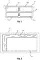
- Fig. 1 schematically shows an electrical insulation layer of a conductor according to embodiments of the present disclosure. Specifically, Fig. 1 shows a conductor arrangement 10 having an insulation layer 20 in which a plurality of conductor strands 15-1, 15-2, 15-3, 15-4 are embedded.
- the insulation layer 20 may have a thickness between 0.5 mm to 2.0 mm.
- the plurality of conductor strands 15-1, 15-2, 15-3, 15-4 form an overall electric conductor, for example a Roebel bar, a coil wire and/or coil turn, a stator winding, etc.
- the conductor strands 15-1, 15-2, 15-3, 15-4 may be referred to as conductors for simplicity.
- the conductor strands may be further interwoven and/or permuted along a longitudinal extension of the conductor in order to reduce the electric resistance in the presence of the skin effect.
- a gap G is provided, for example in order to increase an overall number of windings/turns of a coil and/or to avoid a short circuit between conductor strands of a Roebel bar.
- the conductor arrangement 10 comprises the spatially adjacent conductors 15-1, 15-2, 15-3, 15-4, each having a substantially rectangular cross-section with rounded corners.
- the cross-sectional shape, nor the number of conductors 15-1, 15-2, 15-3, 15-4 is limited to those shown in the drawings.
- each of the conductors 15-1, 15-2, 15-3, 15-4 are enameled conductors, but not limited thereto.
- dividing the conductor into a plurality of conductor strands 15-1, 15-2, 15-3, 15-4 allows to increase the windings/turns of a coil and/or allows to reduce an overall resistance of the conductor in the presence of skin effect, in particular when the conductor strands are longitudinally interwoven and/or permuted regularly. It is necessary to keep the conductor strands reciprocally insulated to avoid a short circuit that would for example reduce the generated magnetic field in the coil and/or increase an electric resistance in a Roebel bar.
- a gap is also present between the conductor and the ground and/or any body (not shown) at ground electric potential.
- the insulation layer 20 insulates the different conductor strands in order to avoid a short circuit between conductor strands.
- the insulation layer 20 may therefore form both an inter-strand insulation and/or a groundwall insulation.
- the conductor for example formed by the conductor strands, together with the insulation layer 20 forms a conductor arrangement 10 that may be used for example in an electric machine, like for example a generator or a motor, forming for example a coil.
- the conductor for example formed by the conductor strands, together with the insulation layer 20 forms a conductor arrangement 10 that may be used for example for transferring electric energy from a generator to a load in an electric circuit, forming for example a Roebel bar arrangement.
- the insulation layer 20 comprises an insulation material obtained through a curing process of a thermosetting material, wherein solid electrically insulating elements 25, such as mica platelets, are present inside the thermoset material.
- solid electrically insulating elements 25 such as mica platelets
- the relationship of the solid insulating elements to the thermosetting material component of the insulation material is between 20:80, preferably between 25:75 and typically about 30:70 by volume in the uncured state.
- composition generally refers to a mixture or a compound of the materials that are involved.
- a composition of a thermosetting material and mica elements may be obtained by mixing the uncured thermosetting material and the insulating elements.
- the thermosetting material and mica platelets are fed, typically gravimetrically fed, into a mixer that produces the composition.
- the composition may generally be a mica platelet-filled liquid resin compound.
- the thermosetting material may be an UV-curable thermosetting resin.
- the insulating elements may be mica particles, typically mica platelets, having a predetermined average particle size. The insulation material, or the thermosetting material component thereof, is typically cured accordingly.
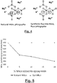
- Fig. 2 shows a detail of an electrical insulation layer of a conductor according to embodiments of the present disclosure.
- Fig. 2 shows a detail of an area E of the section of Fig. 1 .
- the area E may correspond to the upper left corner of a section of the conductor strand 15-1.
- the conductor strand 15-1 may be insulated by an insulation layer 20 that forms a groundwall insulation and/or an inter-strand insulation and/or that insulates the conductor 15-1 from other conductors and/or windings and/or coil turns.
- the insulation layer 20 may be formed by a UV curable mixture comprising an UV curable thermoset resin and a filler, wherein the filler is formed by UV transparent solid platelets 25, for example by synthetic fluorine mica platelets.
- an electrical insulation mixture for forming a layer on a conductor surface comprising an ultra violet (UV) curable thermoset resin and a filler, wherein the filler comprises UV transparent platelets 25 made of a platelet material, wherein UV transparency is given for light in a wavelength range between 300 and 420 nm.
- UV ultra violet
- a platelet may have substantially flake-like shape with its (average) thickness (in a direction perpendicular to a local flake plane) being much smaller than its length and width (measured for a flattened flake if the flake is not completely flat).
- a platelet may be considered to be transparent for example if a radiant flux of UV light incident on the local flake plane is substantially transmitted through the whole platelet and passes through the whole platelet without being attenuated significantly.
- the radiant flux transmitted thought the thickness of the flake and exiting the flake may be for example 85% or more of the incident radiant flux that is incident onto the flake-like platelet
- the surfaces of the platelet may not reflect the UV light back and the platelet material of the platelet may not dissipate or absorb the UV light to a larger degree than expressed by the above threshold.
- the purpose of the UV radiation is to interact with the thermoset resin to activate the photoinitiators that catalyze the cross-linking reaction of the thermoset material.
- the insulation mixture filled with synmica platelets interacts with the UV radiation substantially in the same way as the insulation mixture composed of neat resin (i.e. without synmica platelets) does. This can be achieved when the platelets are substantially UV transparent.
- UV light may be a light with a wavelength between 380 and 420 nm and may for example be produced by a source with an irradiance at the UV emitting window of 4W/cm ⁇ 2 for an emitting window e.g. of 300 mm x 20 mm.
- a total UV power of 240 W may be irradiated by a source that may be e.g. a UV LED, e.g. a UV LED based on SLM Technology.
- a transmittance of 85% or more through the synmica platelets may be obtained.
- the maximum depth of penetration of an UV beam into a non-transparent material has a finite constant value as long as the intensity is not increased.
- the maximum depth of penetration may be a maximum depth at which the radiating flux of the UV light is above a fraction of the radiating flux incident to the non-transparent material.
- the intensity of the beam decays as a function of penetrated depth.
- the thickness of the insulation layer is significantly smaller than the maximum penetration depth, therefore there is substantially no resin curing gradient from the surface to the insulation-conductor interface; the degree of curing is the same throughout the thickness of the insulation layer.
- UV light onto a surface of the platelet, for example emitting a light that propagates in a direction perpendicular to the local flake plane and measuring the radiant flux that passes through the flake plane exiting on the opposite side of the flake as a fraction of the radiant flux incident on the flake.
- the measurement may be carried out focusing a UV light beam onto a surface of the platelet, measuring the radiating power of said beam incident on the flake and the radiating power of the UV light emitted through the flake on the side opposite to the side where the beam is directed towards the flake.
- a transmittance of the platelet with the flake-like shape i.e.
- the radiating power passing through the platelet/flake and reemitted by the platelet/flake as a fraction of the incident power may be 85% or more for wavelengths above 0.2 micrometers, e.g. 0.3 micrometers and/or below 1.0 micrometers, e.g. below 0.4 micrometers.
- the flake-like platelets made of synmica may have a length/size between 3.2 ⁇ m and 14.3 ⁇ m.
- a thickness of the platelets may be between 0.30 ⁇ m and 0.35 ⁇ m.
- the UV transparent light is not reflected back from a surface of the platelets and effectively penetrates the platelet material and the electrical insulation mixture.
- the UV light absorbed by a surface of the platelet material further propagates in the platelet material.
- the UV radiation transmitted through a surface of the platelet material further propagates in the platelet material at least for a depth d corresponding to a maximum diameter/size d of the platelets.
- the material of the platelets is UV transparent, if in the wavelength range between 300 nm and 420 nm the transparency of the material of the platelets is substantially similar to (i.e., at least substantially the same as, with a tolerance of ,e.g., about 10%) the transparency of synthetic fluorine mica (synmica), also known as fluorphlogopite mica.
- the platelet material may be considered UV transparent, if a transmittance of the platelet material is substantially similar to the transmittance of synmica.
- a transmittance of the UV transparent material of the platelets in the wavelength range between 300 nm and 420 nm may be similar to the transmittance of synmica within this wavelength range, for example 90% of the transmittance of synmica or more.
- the transmittance may be a transmittance with respect to a maximum diameter/size of the platelets.
- the transmittance may be a function of the wavelength. It is intended that for each wavelength in the range between 300 nm and 420 nm the transmittance of a layer of thickness d of the platelet material is at least 90% of the transmittance of a layer of thickness d of synmica for the same wavelength and for an arbitrary thickness d , for example a maximum or average thickness/size of the platelets.
- a transmittance of the UV transparent material in the wavelength range between 300 nm and 420 nm may be , for example, equal to or higher than 90% of the transmittance of synmica, within the stated wavelength range.
- the transparency may be the same as or higher than the transmittance of synmica.
- the platelets and/or the platelet material is considered to be UV transparent if for each wavelength in the range between 300 nm and 420 nm the transmittance of a layer of thickness d of the platelet material is at least 90% of the transmittance of a layer of thickness d of synmica for the same wavelength and for an arbitrary thickness d , for example a maximum or average thickness/size of the platelets.
- the platelets and/or the platelet material is considered to be UV transparent if for each wavelength in the range between 200 nm and 420 nm the transmittance of a layer of thickness d of the platelet material is at least 90% of the transmittance of a layer of thickness d of synmica for the same wavelength and for an arbitrary thickness d , for example a maximum or average thickness of the platelets.
- the platelet material is also characterized by a dielectric strength that is substantially the same dielectric strength as synmica, for example 90% or more of the dielectric strength of synmica.
- the platelets do not need to be made of pure platelet material and/or the platelets do not need to be made of pure synmica.
- the platelet material and/or the synmica may contain impurities as long as the tranparence/transmittance and/or the dielectric strength is not substantially affected, for example as long as the transmittace is 90% or more of the transmittance of pure synmica and the dielectric strength is 90% or more of the dielectric strength of pure synmica.
- the platelet material may have a dielectric strength between 115-180 kV/mm, for example 140kV/mm.
- the platelet material may be synmica or may be a material with substantially similar properties of synmica.
- the UV transparent solid platelets 25 ensure that less UV light is absorbed by the mixture that comprises the UV curable thermoset resin and the filler comprising the UV transparent platelets. Therefore the electrical insulation mixture can be advantageously cured by UV light and in particular an elevated curing speed can be maintained to form the insulation layer and in addition the dielectric strength of the insulation layer is increased.
- the UV transparent solid platelets 25 may comprise synthetic fluorine mica platelets.
- the UV transparent solid platelets 25 provide the improved dielectric strength of the electrical insulation mixture, due to the insulation properties of the synthetic fluorine mica and further allow a fast and rapid curing of the UV curable thermoset resin in said mixture as a consequence of the UV transparency of the solid platelets 25.
- the synthetic fluorine mica platelets being substantially UV transparent ensure that the UV light effectively penetrates the mixture curing the UV curable thermoset resin of the mixture.
- UV opaque platelets, formed for example by natural mica may still improve the dielectric strength, but absorbing UV light would prevent an effective and rapid curing of the UV curable thermoset resin in order to rapidly form the insulation layer of the electric conductor.
- the insulation thickness i.e. the thickness of the insulation layer, may have be for example between 0.5 mm to 2.0 mm.
- the concentration of the platelets in the mixture may be between 0 to 20% in weight.
- Fig. 3 shows a flow chart of a method 300 for electrically insulating a metallic conductor according to embodiments of the present disclosure.
- the method 300 for electrically insulating the metallic conductor starts according to 1001.
- the method includes obtaining 1002 an electrical insulation mixture, the mixture including a UV curable thermoset resin and a filler.
- the method further includes forming 1003 a jacketing on a surface of the conductor using the mixture obtained in 1002 and exposing 1004 the mixture to ultraviolet (UV) radiation to cure the mixture, thus forming, from the jacketing, an electrical insulation layer 20 on the surface of the metallic conductor.
- UV ultraviolet
- At least one of obtaining 1002 the mixture, forming 1003 a jacketing, and exposing 1004 the mixture to UV radiation is repeated 1005 one or more times until the whole surface of the conductor is electrically insulated.
- different longitudinal sections of the conductor may be electrically insulated.
- a jacketing unit may be translated along a longitudinal axis of the conductor and forming 1003 the jacketing and exposing 1004 the mixture to UV radiation is carried out iteratively for each longitudinal section of the longitudinally extending conductor.
- the repeating 1005 may be carried out along a wire or a group of wires that may form a coil and/or along turns forming a coil in an electric machine.
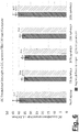
- Fig. 4 illustrates the chemical structure of natural phlogopite mica on the left and of synthetic fluorphlogopite fluorine mica on the right. Hydroxyl groups in the natural mica are replaced by fluorine atoms rendering the synthetic fluorine mica UV transparent while maintaining good electric insulating properties, for example a high dielectric strength of the synthetic mica.
- the synthetic fluorine mica of Fig. 4 may then be used in the method 300 for forming the UV transparent platelets 25 of the filler of the electrical insulation mixture obtained in 1002.
- the synthetic fluorine mica improves the dielectric strength while still allowing a fast UV curing of the mixture.
- the mixture is used to form the electrical insulating layer 20 according to the method 300.
- the solid platelets 25 comprising synthetic fluorine mica improve the dielectric strength of the finally obtained electrical insulating layer 20 while allowing a fast curing when exposing 1004 the mixture to UV radiation according to the method 300.
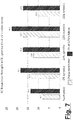
- Fig. 5 shows the maximum jacketing speed in mm/min as a function of the percentage of mica added to epoxy resin, the epoxy resin being a UV curable thermoset resin according to the present disclosure.
- a maximum jacketing speed decreases when the percentage of mica added to the epoxy resin increases.
- a thermoset resin e.g. epoxy resin
- a maximum jacketing speed may be, in accordance with Fig. 5 , 800 mm/min.
- the maximum jacketing speed already decreases to 400 mm/min.
- 20% of mica added to the epoxy resin the maximum jacketing speed may be of only approximately 200 mm/min.
- the maximum jacketing speed remains approximately constant and equal to the maximum jacketing speed obtainable for epoxy resin without any addition of mica platelets.
- the maximum jacketing speed may remain approximately constant and equal to 800 mm/min for any percentage of mica added to the epoxy resin in the range of 0% to 20%.
- the maximum jacketing speed is defined as a maximum speed for which the insulation layer on the conductor has been sufficiently cross-linked by the curing reaction to consider that the thermoset material has hardened.
- the cross-linking reaction is driven by the phtotoinitiator present in the thermoset resin, and the photoinitiator only reacts during the time that it is exposed to UV radiation.
- the insulating layer is e.g. sufficiently regular and/or uniform, for example without voids and/or cracks and/or variations along a longitudinal axis of the conductor.
- Fig. 5 only exemplarily illustrates the effect of the presence of synmica compared to natural mica, showing that for synmica a maximum jacketing speed does not depend on the percentage of added synmica whereas for natural mica the maximum jacketing speed rapidly decreases in function of the percentage of mica added to the epoxy resin.
- the maximum jacketing speed may vary. Nevertheless when synmica is added the maximum jacketing speed remains substantially constant in function of the percentage of synmica added to the UV curable thermoset resin and/or a decrease of the maximum jacketing speed in function of the percentage of mica added to the epoxy resin is much lower than for the addition of natural mica.
- Fig. 5 shows a maximum jacketing speed that is obtainable when exposing a mixture for forming an insulating layer on a conductor surface to ultraviolet (UV) radiation to cure the mixture according to embodiments of the present disclosure.
- UV ultraviolet
- the cumulative distribution is a two-parameter Weibull cumulative distribution.
- the parameter ⁇ forms a scale parameter and ⁇ forms a shape parameter.
- the shape parameter ⁇ indicates a scattering of the statistical distribution F ⁇ ( t ) .
- F ⁇ ( t ) When ⁇ increases the cumulative distribution function F ⁇ ( t ) becomes steeper.
- the probability density function converges to a Dirac delta distribution centered at ⁇ and F ⁇ ( t ) to a unit step function centered in ⁇ and with F ⁇ ( ⁇ ) ⁇ 0,632 according to the previous equation.
- the breakdown strength ⁇ may be measured for example in kV/mm.
- Fig. 6 shows values for the scale parameter ⁇ in kV/mm for neat epoxy, for epoxy with the addition of 5% synmica, 10% synmica, 15% synmica, and 20% synmica respectively. Furthermore Fig. 6 shows the experimentally determined average breakdown strength in kV/mm. We observe that the average breakdown strength is centered around the scale parameter ⁇ . Therefore Fig. 6 describes the scale parameter ⁇ and the average breakdown strength of an insulation layer according to embodiments of the present disclosure. Fig. 6 shows in particular an average breakdown strength and a scale parameter for an electrical insulation formed by an electrical insulation mixture comprising an UV curable thermoset resin and a filler comprising UV transparent platelets comprising synthetic fluorine mica (synmica), according to embodiments of the present disclosure.
- synmica can cause an initial decrease in the average breakdown strength and/or the scale parameter ⁇ , but when 20% synmica is used the breakdown strength and the scale parameter ⁇ significantly improve.
- Fig. 6 only exemplarily shows a dependency on the percentage of synmica according to embodiments of the present disclosure.
- t 0.0001 is indicated with "Life at 0.01% failure”.
- the shape parameter ⁇ increases to 17.3 compared to the shape parameter ⁇ for neat epoxy of only 8.2. This results in a significant improvement of the steepness of the cumulative distribution F ⁇ ( t ) and in a reduced scattering around ⁇ .
- an electrical insulation mixture for forming a layer on a conductor surface comprsing an UV curable thermoset resin and a filler wherein the filler comprises UV transparent platelets comprsing synmica (synthetic fluorine mica) according to the present disclosure is beneficial for an improved electrical insulation, increasing a shape parameter ⁇ and/or the breakdown strength for a 0.01% failure, while maintaining an elevate maximum jacketing speed as illustrated in Fig. 5 .
- an electrical insulation mixture for forming a layer on a conductor surface comprising an UV curable thermoset resin and a filler, wherein the filler comprises UV transparent platelets made of a platelet material, wherein UV transparency is given for for light in a wavelength range between 300 and 420 nm.
- the UV transparent platelets comprise solid platelets having a predominantly crystalline molecular structure with a density above 2 g/cm ⁇ 3.
- the platelet material of the UV transparent platelets comprises synthetic fluorine mica platelets.
- the relation of the UV transparent platelets with respect to the mixture is less than or equal to 25% wt.-%, optionally less than or equal to 20% wt.-% or less than or equal to 15% wt-%.
- the platelet material has a dielectric strength of at least 180 kV/mm.
- the mixture has a dielectric strength, for a failure probability of 0.01%, of more than 17 kV/mm, optionally more than 22 kV/mm or more than 22.5 kV/mm.
- Some embodiments of the present disclosure are formed by a method for electrically insulating a metallic conductor, the method comprising: obtaining an electrical insulation mixture according any one of the preceding claims; forming a jacketing on a surface of the metallic conductor using the mixture thus obtained; exposing the mixture to ultraviolet radiation to cure the mixture, thus forming, from the jacketing, an electrical insulation layer on the surface of the metallic conductor.
- the thickness of the insulation layer is not particularly limited. For example, the space in between two strands can be entirely filled by the insulation layer(s).
- the metallic conductor comprises one or more conductor strands
- the electrical insulation layer is formed on each of one or more of the conductor strands, optionally on each of the conductor strands.
- an electrical insulation layer is formed on each of at least two adjacent conductor strands for providing simultaneously an inter-strand insulation and an outer groundwall insulation of the metallic conductor.
- Some embodiments of the present disclosure are formed by a metallic conductor with an electrical insulation layer obtained by curing the electrical insulation mixture.
- the metallic conductor has an electrical insulation obtained with methods of the present disclosure.
- the technology described in the present disclosure may help to improve in an electrical insulation mixture and a method for electrically insulating a metallic conductor and a metallic conductor with an electrical insulation layer.
- the electrical insulation layer can be obtained curing with UV radiation the mixture after forming a jacketing on a surface of the conductor; the jacketing can be carried out at a jacketing speed that does not decrease in the presence of an increasing percentage of UV transparent synthetic mica platelets in the filler of the mixture; the UV transparent synthetic mica platelets in the filler of the mixture allow a fast jacketing and curing, while providing good and improved characteristics of the electrical insulation layer, like for example an increased shape parameter ⁇ , and/or an increased breakdown strength, characterized for example by a higher breakdown strength for a 0.01% failure and/or a higher scale parameter ⁇ of a cumulative distribution function F ⁇ ( t ) of the breakdown strength ⁇ and/or an increased average breakdown strength, for example a measured average breakdown strength of the insulation layer.
Landscapes
- Chemical & Material Sciences (AREA)
- Organic Chemistry (AREA)
- Medicinal Chemistry (AREA)
- Polymers & Plastics (AREA)
- Health & Medical Sciences (AREA)
- Chemical Kinetics & Catalysis (AREA)
- Physics & Mathematics (AREA)
- Spectroscopy & Molecular Physics (AREA)
- Inorganic Chemistry (AREA)
- Dispersion Chemistry (AREA)
- Power Engineering (AREA)
- Engineering & Computer Science (AREA)
- Organic Insulating Materials (AREA)
- Compositions Of Macromolecular Compounds (AREA)
- Insulating Bodies (AREA)
- Insulation, Fastening Of Motor, Generator Windings (AREA)
Priority Applications (4)
| Application Number | Priority Date | Filing Date | Title |
|---|---|---|---|
| EP20173534.7A EP3907251A1 (fr) | 2020-05-07 | 2020-05-07 | Plaquettes solides utilisées en tant qu'agent de remplissage dans une résine thermodurcie durcissable par uv pour améliorer l'isolation électrique de barres conductrices de haute tension |
| PCT/EP2021/062192 WO2021224473A1 (fr) | 2020-05-07 | 2021-05-07 | Plaquettes solides utilisées comme charge dans une résine thermodurcissable durcissable aux uv pour améliorer l'isolation électrique de barres conductrices haute tension |
| CN202180042836.6A CN115769314B (zh) | 2020-05-07 | 2021-05-07 | 用作uv可固化热固性树脂中的填料以增强高压导体线棒的电绝缘的固体晶体结构 |
| US17/923,734 US20230178263A1 (en) | 2020-05-07 | 2021-05-07 | Solid platelets used as filler in a uv curable thermoset resin to enhance the electrical insulation of high voltage conductor bars |
Applications Claiming Priority (1)
| Application Number | Priority Date | Filing Date | Title |
|---|---|---|---|
| EP20173534.7A EP3907251A1 (fr) | 2020-05-07 | 2020-05-07 | Plaquettes solides utilisées en tant qu'agent de remplissage dans une résine thermodurcie durcissable par uv pour améliorer l'isolation électrique de barres conductrices de haute tension |
Publications (1)
| Publication Number | Publication Date |
|---|---|
| EP3907251A1 true EP3907251A1 (fr) | 2021-11-10 |
Family
ID=70617020
Family Applications (1)
| Application Number | Title | Priority Date | Filing Date |
|---|---|---|---|
| EP20173534.7A Pending EP3907251A1 (fr) | 2020-05-07 | 2020-05-07 | Plaquettes solides utilisées en tant qu'agent de remplissage dans une résine thermodurcie durcissable par uv pour améliorer l'isolation électrique de barres conductrices de haute tension |
Country Status (4)
| Country | Link |
|---|---|
| US (1) | US20230178263A1 (fr) |
| EP (1) | EP3907251A1 (fr) |
| CN (1) | CN115769314B (fr) |
| WO (1) | WO2021224473A1 (fr) |
Families Citing this family (1)
| Publication number | Priority date | Publication date | Assignee | Title |
|---|---|---|---|---|
| EP4618109A1 (fr) * | 2024-03-13 | 2025-09-17 | Abb Schweiz Ag | Procédé de fabrication de bobine utilisant des bandes de mica transparentes aux uv pour l'isolation de mur de sol |
Citations (3)
| Publication number | Priority date | Publication date | Assignee | Title |
|---|---|---|---|---|
| JPS6019127B2 (ja) * | 1979-12-03 | 1985-05-14 | 株式会社安川電機 | 電気機器線輪の絶縁 |
| JPH04251547A (ja) * | 1990-12-28 | 1992-09-07 | Yaskawa Electric Corp | 耐熱性絶縁線輪 |
| EP3608923A1 (fr) * | 2018-08-10 | 2020-02-12 | ABB Schweiz AG | Appareil et procédé pour appliquer un matériau d'isolation sur un conducteur |
Family Cites Families (13)
| Publication number | Priority date | Publication date | Assignee | Title |
|---|---|---|---|---|
| US4618632A (en) * | 1985-02-07 | 1986-10-21 | Westinghouse Electric Corp. | UV curable high tensile strength resin composition |
| US4892773A (en) * | 1987-07-30 | 1990-01-09 | Westinghouse Electric Corp. | Preparation of amorphous metal core for use in transformer |
| GB9522656D0 (en) * | 1995-11-04 | 1996-01-03 | Zeneca Ltd | Mould |
| JP3577172B2 (ja) * | 1996-09-02 | 2004-10-13 | 積水化学工業株式会社 | 難燃性光重合性組成物及びこれを用いた難燃性粘着テープ |
| US6504982B1 (en) * | 1999-06-30 | 2003-01-07 | Alcatel | Incorporation of UV transparent perlescent pigments to UV curable optical fiber materials |
| US6415090B1 (en) * | 2000-11-13 | 2002-07-02 | Fitel Usa Corp. | Optical fiber coatings |
| DE10248324A1 (de) * | 2002-10-17 | 2004-05-06 | Basf Coatings Ag | Thermisch und mit aktinischer Strahlung härtbarer Beschichtungsstoff und Verfahren zum Beschichten miktoporöser Oberflächen |
| JP2006100463A (ja) * | 2004-09-29 | 2006-04-13 | Ibiden Co Ltd | プリント配線板用層間絶縁層、プリント配線板およびその製造方法 |
| JP4590473B2 (ja) * | 2008-12-10 | 2010-12-01 | 大日本塗料株式会社 | 型内被覆組成物及び型内被覆成形体 |
| EP2596936B1 (fr) * | 2011-11-24 | 2015-09-09 | ABB Research Ltd. | Moule et procédé de production d'articles formés à partir d'une composition durcissable aux UV |
| JP6675543B2 (ja) * | 2016-02-05 | 2020-04-01 | 北川工業株式会社 | 熱伝導部材、熱伝導部材の製造方法及びシリコーン混合物 |
| EP3635849A1 (fr) * | 2017-06-09 | 2020-04-15 | ABB Schweiz AG | Machine électrique dotée d'un système conducteur et isolation associée |
| JP6759323B2 (ja) * | 2018-03-28 | 2020-09-23 | 太陽インキ製造株式会社 | 感光性樹脂組成物、2液型感光性樹脂組成物、ドライフィルムおよびプリント配線板 |
-
2020
- 2020-05-07 EP EP20173534.7A patent/EP3907251A1/fr active Pending
-
2021
- 2021-05-07 WO PCT/EP2021/062192 patent/WO2021224473A1/fr not_active Ceased
- 2021-05-07 US US17/923,734 patent/US20230178263A1/en active Pending
- 2021-05-07 CN CN202180042836.6A patent/CN115769314B/zh active Active
Patent Citations (3)
| Publication number | Priority date | Publication date | Assignee | Title |
|---|---|---|---|---|
| JPS6019127B2 (ja) * | 1979-12-03 | 1985-05-14 | 株式会社安川電機 | 電気機器線輪の絶縁 |
| JPH04251547A (ja) * | 1990-12-28 | 1992-09-07 | Yaskawa Electric Corp | 耐熱性絶縁線輪 |
| EP3608923A1 (fr) * | 2018-08-10 | 2020-02-12 | ABB Schweiz AG | Appareil et procédé pour appliquer un matériau d'isolation sur un conducteur |
Also Published As
| Publication number | Publication date |
|---|---|
| US20230178263A1 (en) | 2023-06-08 |
| CN115769314B (zh) | 2025-07-15 |
| WO2021224473A1 (fr) | 2021-11-11 |
| CN115769314A (zh) | 2023-03-07 |
Similar Documents
| Publication | Publication Date | Title |
|---|---|---|
| Nazir et al. | Accelerated ultraviolet weathering investigation on micro‐/nano‐SiO2 filled silicone rubber composites | |
| Preetha et al. | Partial discharge resistant characteristics of epoxy nanocomposites | |
| EP2569362A1 (fr) | Isolation pour machines électriques rotatives | |
| Raetzke et al. | Tree initiation characteristics of epoxy resin and epoxy/clay nanocomoposite | |
| EP2362399A1 (fr) | Procédé de fabrication d'un matériau anti-effluves d'extrémités et une protection anti-effluves d'extrémités dotée de ce matériau anti-effluves d'extrémités | |
| WO2011138413A2 (fr) | Matériau d'isolation électrique et bande d'isolation pour une isolation électrique d'une moyenne tension/haute tension | |
| Thangabalan et al. | Understanding the surface condition of silicone rubber nanocomposite due to corona aging using AFM imaging and LIBS spectroscopy | |
| EP3907251A1 (fr) | Plaquettes solides utilisées en tant qu'agent de remplissage dans une résine thermodurcie durcissable par uv pour améliorer l'isolation électrique de barres conductrices de haute tension | |
| Gutierrez et al. | Effect of protrusions in HVDC cables | |
| Tanaka et al. | PD resistance evaluation of LDPE/MgO nanocomposite by a rod-to-plane electrode system | |
| EP2810359A2 (fr) | Matière de protection anti-effluves pour une machine électrique | |
| Khelifa et al. | Effect of MgO nanoparticles on the AC breakdown voltage, partial discharge activity, and electrostatic charging tendency of natural ester | |
| CN106063088A (zh) | 用于电机的防电晕系统,特别是外部防电晕系统 | |
| Kúdelčík et al. | The effect of SiO2 nano-filler on dielectric properties of epoxy resin | |
| Rahman et al. | Effect of nano filler concentration on leakage current and partial discharge properties of zepoxy nano composites | |
| Nguyen et al. | Nanostructured insulation for high torque density electric propulsion motors | |
| Danikas et al. | A short review on polymer nanocomposites for enameled wires: Possibilities and perspectives | |
| Nguyen et al. | Silica nanofilled varnish designed for electrical insulation of low voltage inverter-fed motors | |
| Thabet et al. | Performance comparison of selection nanoparticles for insulation of three core belted power cables | |
| CN106716788B (zh) | 电机的电晕屏蔽系统 | |
| Pradeep et al. | Effect of interphase permittivity on the electric field distribution of epoxy nanocomposites | |
| Liu et al. | Investigation on heating aging mechanism of cellulose paper for oil-immersed transformer main insulation | |
| Danikas et al. | Interfaces in high voltage engineering: A most important question for conventional solid insulating materials as well as for nanocomposite polymers | |
| Douar et al. | Influence of the rise rate of voltage and leakage distance on flashover gradient and partial discharges level for various polymeric materials under AC stress | |
| Kumagai et al. | Tracking and erosion resistance stability of highly filled silicone and alloy materials against electrical and environmental stresses |
Legal Events
| Date | Code | Title | Description |
|---|---|---|---|
| PUAI | Public reference made under article 153(3) epc to a published international application that has entered the european phase |
Free format text: ORIGINAL CODE: 0009012 |
|
| STAA | Information on the status of an ep patent application or granted ep patent |
Free format text: STATUS: THE APPLICATION HAS BEEN PUBLISHED |
|
| AK | Designated contracting states |
Kind code of ref document: A1 Designated state(s): AL AT BE BG CH CY CZ DE DK EE ES FI FR GB GR HR HU IE IS IT LI LT LU LV MC MK MT NL NO PL PT RO RS SE SI SK SM TR |
|
| B565 | Issuance of search results under rule 164(2) epc |
Effective date: 20201012 |
|
| STAA | Information on the status of an ep patent application or granted ep patent |
Free format text: STATUS: REQUEST FOR EXAMINATION WAS MADE |
|
| 17P | Request for examination filed |
Effective date: 20220509 |
|
| RBV | Designated contracting states (corrected) |
Designated state(s): AL AT BE BG CH CY CZ DE DK EE ES FI FR GB GR HR HU IE IS IT LI LT LU LV MC MK MT NL NO PL PT RO RS SE SI SK SM TR |
|
| STAA | Information on the status of an ep patent application or granted ep patent |
Free format text: STATUS: EXAMINATION IS IN PROGRESS |
|
| 17Q | First examination report despatched |
Effective date: 20241031 |