EP3907304B1 - Hochfestes feuerverzinktes stahlblech und verfahren zur herstellung davon - Google Patents
Hochfestes feuerverzinktes stahlblech und verfahren zur herstellung davon Download PDFInfo
- Publication number
- EP3907304B1 EP3907304B1 EP20778920.7A EP20778920A EP3907304B1 EP 3907304 B1 EP3907304 B1 EP 3907304B1 EP 20778920 A EP20778920 A EP 20778920A EP 3907304 B1 EP3907304 B1 EP 3907304B1
- Authority
- EP
- European Patent Office
- Prior art keywords
- steel sheet
- less
- hot
- dip
- ultrasound
- Prior art date
- Legal status (The legal status is an assumption and is not a legal conclusion. Google has not performed a legal analysis and makes no representation as to the accuracy of the status listed.)
- Active
Links
Images

Classifications
-
- C—CHEMISTRY; METALLURGY
- C22—METALLURGY; FERROUS OR NON-FERROUS ALLOYS; TREATMENT OF ALLOYS OR NON-FERROUS METALS
- C22C—ALLOYS
- C22C38/00—Ferrous alloys, e.g. steel alloys
- C22C38/02—Ferrous alloys, e.g. steel alloys containing silicon
-
- C—CHEMISTRY; METALLURGY
- C23—COATING METALLIC MATERIAL; COATING MATERIAL WITH METALLIC MATERIAL; CHEMICAL SURFACE TREATMENT; DIFFUSION TREATMENT OF METALLIC MATERIAL; COATING BY VACUUM EVAPORATION, BY SPUTTERING, BY ION IMPLANTATION OR BY CHEMICAL VAPOUR DEPOSITION, IN GENERAL; INHIBITING CORROSION OF METALLIC MATERIAL OR INCRUSTATION IN GENERAL
- C23C—COATING METALLIC MATERIAL; COATING MATERIAL WITH METALLIC MATERIAL; SURFACE TREATMENT OF METALLIC MATERIAL BY DIFFUSION INTO THE SURFACE, BY CHEMICAL CONVERSION OR SUBSTITUTION; COATING BY VACUUM EVAPORATION, BY SPUTTERING, BY ION IMPLANTATION OR BY CHEMICAL VAPOUR DEPOSITION, IN GENERAL
- C23C2/00—Hot-dipping or immersion processes for applying the coating material in the molten state without affecting the shape; Apparatus therefor
- C23C2/02—Pretreatment of the material to be coated, e.g. for coating on selected surface areas
- C23C2/024—Pretreatment of the material to be coated, e.g. for coating on selected surface areas by cleaning or etching
-
- B—PERFORMING OPERATIONS; TRANSPORTING
- B32—LAYERED PRODUCTS
- B32B—LAYERED PRODUCTS, i.e. PRODUCTS BUILT-UP OF STRATA OF FLAT OR NON-FLAT, e.g. CELLULAR OR HONEYCOMB, FORM
- B32B15/00—Layered products comprising a layer of metal
- B32B15/01—Layered products comprising a layer of metal all layers being exclusively metallic
- B32B15/013—Layered products comprising a layer of metal all layers being exclusively metallic one layer being formed of an iron alloy or steel, another layer being formed of a metal other than iron or aluminium
-
- C—CHEMISTRY; METALLURGY
- C21—METALLURGY OF IRON
- C21D—MODIFYING THE PHYSICAL STRUCTURE OF FERROUS METALS; GENERAL DEVICES FOR HEAT TREATMENT OF FERROUS OR NON-FERROUS METALS OR ALLOYS; MAKING METAL MALLEABLE, e.g. BY DECARBURISATION OR TEMPERING
- C21D1/00—General methods or devices for heat treatment, e.g. annealing, hardening, quenching or tempering
- C21D1/04—General methods or devices for heat treatment, e.g. annealing, hardening, quenching or tempering with simultaneous application of supersonic waves, magnetic or electric fields
-
- C—CHEMISTRY; METALLURGY
- C21—METALLURGY OF IRON
- C21D—MODIFYING THE PHYSICAL STRUCTURE OF FERROUS METALS; GENERAL DEVICES FOR HEAT TREATMENT OF FERROUS OR NON-FERROUS METALS OR ALLOYS; MAKING METAL MALLEABLE, e.g. BY DECARBURISATION OR TEMPERING
- C21D1/00—General methods or devices for heat treatment, e.g. annealing, hardening, quenching or tempering
- C21D1/26—Methods of annealing
-
- C—CHEMISTRY; METALLURGY
- C21—METALLURGY OF IRON
- C21D—MODIFYING THE PHYSICAL STRUCTURE OF FERROUS METALS; GENERAL DEVICES FOR HEAT TREATMENT OF FERROUS OR NON-FERROUS METALS OR ALLOYS; MAKING METAL MALLEABLE, e.g. BY DECARBURISATION OR TEMPERING
- C21D1/00—General methods or devices for heat treatment, e.g. annealing, hardening, quenching or tempering
- C21D1/74—Methods of treatment in inert gas, controlled atmosphere, vacuum or pulverulent material
- C21D1/76—Adjusting the composition of the atmosphere
-
- C—CHEMISTRY; METALLURGY
- C21—METALLURGY OF IRON
- C21D—MODIFYING THE PHYSICAL STRUCTURE OF FERROUS METALS; GENERAL DEVICES FOR HEAT TREATMENT OF FERROUS OR NON-FERROUS METALS OR ALLOYS; MAKING METAL MALLEABLE, e.g. BY DECARBURISATION OR TEMPERING
- C21D8/00—Modifying the physical properties of ferrous metals or ferrous alloys by deformation combined with, or followed by, heat treatment
- C21D8/02—Modifying the physical properties of ferrous metals or ferrous alloys by deformation combined with, or followed by, heat treatment during manufacturing of plates or strips
- C21D8/0247—Modifying the physical properties of ferrous metals or ferrous alloys by deformation combined with, or followed by, heat treatment during manufacturing of plates or strips characterised by the heat treatment
- C21D8/0273—Final recrystallisation annealing
-
- C—CHEMISTRY; METALLURGY
- C21—METALLURGY OF IRON
- C21D—MODIFYING THE PHYSICAL STRUCTURE OF FERROUS METALS; GENERAL DEVICES FOR HEAT TREATMENT OF FERROUS OR NON-FERROUS METALS OR ALLOYS; MAKING METAL MALLEABLE, e.g. BY DECARBURISATION OR TEMPERING
- C21D8/00—Modifying the physical properties of ferrous metals or ferrous alloys by deformation combined with, or followed by, heat treatment
- C21D8/02—Modifying the physical properties of ferrous metals or ferrous alloys by deformation combined with, or followed by, heat treatment during manufacturing of plates or strips
- C21D8/0278—Modifying the physical properties of ferrous metals or ferrous alloys by deformation combined with, or followed by, heat treatment during manufacturing of plates or strips involving a particular surface treatment
-
- C—CHEMISTRY; METALLURGY
- C21—METALLURGY OF IRON
- C21D—MODIFYING THE PHYSICAL STRUCTURE OF FERROUS METALS; GENERAL DEVICES FOR HEAT TREATMENT OF FERROUS OR NON-FERROUS METALS OR ALLOYS; MAKING METAL MALLEABLE, e.g. BY DECARBURISATION OR TEMPERING
- C21D9/00—Heat treatment, e.g. annealing, hardening, quenching or tempering, adapted for particular articles; Furnaces therefor
- C21D9/0006—Details, accessories not peculiar to any of the following furnaces
- C21D9/0012—Rolls; Roll arrangements
-
- C—CHEMISTRY; METALLURGY
- C21—METALLURGY OF IRON
- C21D—MODIFYING THE PHYSICAL STRUCTURE OF FERROUS METALS; GENERAL DEVICES FOR HEAT TREATMENT OF FERROUS OR NON-FERROUS METALS OR ALLOYS; MAKING METAL MALLEABLE, e.g. BY DECARBURISATION OR TEMPERING
- C21D9/00—Heat treatment, e.g. annealing, hardening, quenching or tempering, adapted for particular articles; Furnaces therefor
- C21D9/46—Heat treatment, e.g. annealing, hardening, quenching or tempering, adapted for particular articles; Furnaces therefor for sheet metals
-
- C—CHEMISTRY; METALLURGY
- C22—METALLURGY; FERROUS OR NON-FERROUS ALLOYS; TREATMENT OF ALLOYS OR NON-FERROUS METALS
- C22C—ALLOYS
- C22C18/00—Alloys based on zinc
-
- C—CHEMISTRY; METALLURGY
- C22—METALLURGY; FERROUS OR NON-FERROUS ALLOYS; TREATMENT OF ALLOYS OR NON-FERROUS METALS
- C22C—ALLOYS
- C22C38/00—Ferrous alloys, e.g. steel alloys
- C22C38/008—Ferrous alloys, e.g. steel alloys containing tin
-
- C—CHEMISTRY; METALLURGY
- C22—METALLURGY; FERROUS OR NON-FERROUS ALLOYS; TREATMENT OF ALLOYS OR NON-FERROUS METALS
- C22C—ALLOYS
- C22C38/00—Ferrous alloys, e.g. steel alloys
- C22C38/04—Ferrous alloys, e.g. steel alloys containing manganese
-
- C—CHEMISTRY; METALLURGY
- C22—METALLURGY; FERROUS OR NON-FERROUS ALLOYS; TREATMENT OF ALLOYS OR NON-FERROUS METALS
- C22C—ALLOYS
- C22C38/00—Ferrous alloys, e.g. steel alloys
- C22C38/08—Ferrous alloys, e.g. steel alloys containing nickel
-
- C—CHEMISTRY; METALLURGY
- C22—METALLURGY; FERROUS OR NON-FERROUS ALLOYS; TREATMENT OF ALLOYS OR NON-FERROUS METALS
- C22C—ALLOYS
- C22C38/00—Ferrous alloys, e.g. steel alloys
- C22C38/12—Ferrous alloys, e.g. steel alloys containing tungsten, tantalum, molybdenum, vanadium, or niobium
-
- C—CHEMISTRY; METALLURGY
- C22—METALLURGY; FERROUS OR NON-FERROUS ALLOYS; TREATMENT OF ALLOYS OR NON-FERROUS METALS
- C22C—ALLOYS
- C22C38/00—Ferrous alloys, e.g. steel alloys
- C22C38/16—Ferrous alloys, e.g. steel alloys containing copper
-
- C—CHEMISTRY; METALLURGY
- C22—METALLURGY; FERROUS OR NON-FERROUS ALLOYS; TREATMENT OF ALLOYS OR NON-FERROUS METALS
- C22C—ALLOYS
- C22C38/00—Ferrous alloys, e.g. steel alloys
- C22C38/18—Ferrous alloys, e.g. steel alloys containing chromium
-
- C—CHEMISTRY; METALLURGY
- C22—METALLURGY; FERROUS OR NON-FERROUS ALLOYS; TREATMENT OF ALLOYS OR NON-FERROUS METALS
- C22C—ALLOYS
- C22C38/00—Ferrous alloys, e.g. steel alloys
- C22C38/18—Ferrous alloys, e.g. steel alloys containing chromium
- C22C38/22—Ferrous alloys, e.g. steel alloys containing chromium with molybdenum or tungsten
-
- C—CHEMISTRY; METALLURGY
- C22—METALLURGY; FERROUS OR NON-FERROUS ALLOYS; TREATMENT OF ALLOYS OR NON-FERROUS METALS
- C22C—ALLOYS
- C22C38/00—Ferrous alloys, e.g. steel alloys
- C22C38/18—Ferrous alloys, e.g. steel alloys containing chromium
- C22C38/26—Ferrous alloys, e.g. steel alloys containing chromium with niobium or tantalum
-
- C—CHEMISTRY; METALLURGY
- C22—METALLURGY; FERROUS OR NON-FERROUS ALLOYS; TREATMENT OF ALLOYS OR NON-FERROUS METALS
- C22C—ALLOYS
- C22C38/00—Ferrous alloys, e.g. steel alloys
- C22C38/18—Ferrous alloys, e.g. steel alloys containing chromium
- C22C38/28—Ferrous alloys, e.g. steel alloys containing chromium with titanium or zirconium
-
- C—CHEMISTRY; METALLURGY
- C22—METALLURGY; FERROUS OR NON-FERROUS ALLOYS; TREATMENT OF ALLOYS OR NON-FERROUS METALS
- C22C—ALLOYS
- C22C38/00—Ferrous alloys, e.g. steel alloys
- C22C38/18—Ferrous alloys, e.g. steel alloys containing chromium
- C22C38/32—Ferrous alloys, e.g. steel alloys containing chromium with boron
-
- C—CHEMISTRY; METALLURGY
- C22—METALLURGY; FERROUS OR NON-FERROUS ALLOYS; TREATMENT OF ALLOYS OR NON-FERROUS METALS
- C22C—ALLOYS
- C22C38/00—Ferrous alloys, e.g. steel alloys
- C22C38/18—Ferrous alloys, e.g. steel alloys containing chromium
- C22C38/38—Ferrous alloys, e.g. steel alloys containing chromium with more than 1.5% by weight of manganese
-
- C—CHEMISTRY; METALLURGY
- C22—METALLURGY; FERROUS OR NON-FERROUS ALLOYS; TREATMENT OF ALLOYS OR NON-FERROUS METALS
- C22C—ALLOYS
- C22C38/00—Ferrous alloys, e.g. steel alloys
- C22C38/60—Ferrous alloys, e.g. steel alloys containing lead, selenium, tellurium, or antimony, or more than 0.04% by weight of sulfur
-
- C—CHEMISTRY; METALLURGY
- C23—COATING METALLIC MATERIAL; COATING MATERIAL WITH METALLIC MATERIAL; CHEMICAL SURFACE TREATMENT; DIFFUSION TREATMENT OF METALLIC MATERIAL; COATING BY VACUUM EVAPORATION, BY SPUTTERING, BY ION IMPLANTATION OR BY CHEMICAL VAPOUR DEPOSITION, IN GENERAL; INHIBITING CORROSION OF METALLIC MATERIAL OR INCRUSTATION IN GENERAL
- C23C—COATING METALLIC MATERIAL; COATING MATERIAL WITH METALLIC MATERIAL; SURFACE TREATMENT OF METALLIC MATERIAL BY DIFFUSION INTO THE SURFACE, BY CHEMICAL CONVERSION OR SUBSTITUTION; COATING BY VACUUM EVAPORATION, BY SPUTTERING, BY ION IMPLANTATION OR BY CHEMICAL VAPOUR DEPOSITION, IN GENERAL
- C23C2/00—Hot-dipping or immersion processes for applying the coating material in the molten state without affecting the shape; Apparatus therefor
- C23C2/02—Pretreatment of the material to be coated, e.g. for coating on selected surface areas
-
- C—CHEMISTRY; METALLURGY
- C23—COATING METALLIC MATERIAL; COATING MATERIAL WITH METALLIC MATERIAL; CHEMICAL SURFACE TREATMENT; DIFFUSION TREATMENT OF METALLIC MATERIAL; COATING BY VACUUM EVAPORATION, BY SPUTTERING, BY ION IMPLANTATION OR BY CHEMICAL VAPOUR DEPOSITION, IN GENERAL; INHIBITING CORROSION OF METALLIC MATERIAL OR INCRUSTATION IN GENERAL
- C23C—COATING METALLIC MATERIAL; COATING MATERIAL WITH METALLIC MATERIAL; SURFACE TREATMENT OF METALLIC MATERIAL BY DIFFUSION INTO THE SURFACE, BY CHEMICAL CONVERSION OR SUBSTITUTION; COATING BY VACUUM EVAPORATION, BY SPUTTERING, BY ION IMPLANTATION OR BY CHEMICAL VAPOUR DEPOSITION, IN GENERAL
- C23C2/00—Hot-dipping or immersion processes for applying the coating material in the molten state without affecting the shape; Apparatus therefor
- C23C2/02—Pretreatment of the material to be coated, e.g. for coating on selected surface areas
- C23C2/022—Pretreatment of the material to be coated, e.g. for coating on selected surface areas by heating
-
- C—CHEMISTRY; METALLURGY
- C23—COATING METALLIC MATERIAL; COATING MATERIAL WITH METALLIC MATERIAL; CHEMICAL SURFACE TREATMENT; DIFFUSION TREATMENT OF METALLIC MATERIAL; COATING BY VACUUM EVAPORATION, BY SPUTTERING, BY ION IMPLANTATION OR BY CHEMICAL VAPOUR DEPOSITION, IN GENERAL; INHIBITING CORROSION OF METALLIC MATERIAL OR INCRUSTATION IN GENERAL
- C23C—COATING METALLIC MATERIAL; COATING MATERIAL WITH METALLIC MATERIAL; SURFACE TREATMENT OF METALLIC MATERIAL BY DIFFUSION INTO THE SURFACE, BY CHEMICAL CONVERSION OR SUBSTITUTION; COATING BY VACUUM EVAPORATION, BY SPUTTERING, BY ION IMPLANTATION OR BY CHEMICAL VAPOUR DEPOSITION, IN GENERAL
- C23C2/00—Hot-dipping or immersion processes for applying the coating material in the molten state without affecting the shape; Apparatus therefor
- C23C2/02—Pretreatment of the material to be coated, e.g. for coating on selected surface areas
- C23C2/022—Pretreatment of the material to be coated, e.g. for coating on selected surface areas by heating
- C23C2/0222—Pretreatment of the material to be coated, e.g. for coating on selected surface areas by heating in a reactive atmosphere, e.g. oxidising or reducing atmosphere
-
- C—CHEMISTRY; METALLURGY
- C23—COATING METALLIC MATERIAL; COATING MATERIAL WITH METALLIC MATERIAL; CHEMICAL SURFACE TREATMENT; DIFFUSION TREATMENT OF METALLIC MATERIAL; COATING BY VACUUM EVAPORATION, BY SPUTTERING, BY ION IMPLANTATION OR BY CHEMICAL VAPOUR DEPOSITION, IN GENERAL; INHIBITING CORROSION OF METALLIC MATERIAL OR INCRUSTATION IN GENERAL
- C23C—COATING METALLIC MATERIAL; COATING MATERIAL WITH METALLIC MATERIAL; SURFACE TREATMENT OF METALLIC MATERIAL BY DIFFUSION INTO THE SURFACE, BY CHEMICAL CONVERSION OR SUBSTITUTION; COATING BY VACUUM EVAPORATION, BY SPUTTERING, BY ION IMPLANTATION OR BY CHEMICAL VAPOUR DEPOSITION, IN GENERAL
- C23C2/00—Hot-dipping or immersion processes for applying the coating material in the molten state without affecting the shape; Apparatus therefor
- C23C2/04—Hot-dipping or immersion processes for applying the coating material in the molten state without affecting the shape; Apparatus therefor characterised by the coating material
- C23C2/06—Zinc or cadmium or alloys based thereon
-
- C—CHEMISTRY; METALLURGY
- C23—COATING METALLIC MATERIAL; COATING MATERIAL WITH METALLIC MATERIAL; CHEMICAL SURFACE TREATMENT; DIFFUSION TREATMENT OF METALLIC MATERIAL; COATING BY VACUUM EVAPORATION, BY SPUTTERING, BY ION IMPLANTATION OR BY CHEMICAL VAPOUR DEPOSITION, IN GENERAL; INHIBITING CORROSION OF METALLIC MATERIAL OR INCRUSTATION IN GENERAL
- C23C—COATING METALLIC MATERIAL; COATING MATERIAL WITH METALLIC MATERIAL; SURFACE TREATMENT OF METALLIC MATERIAL BY DIFFUSION INTO THE SURFACE, BY CHEMICAL CONVERSION OR SUBSTITUTION; COATING BY VACUUM EVAPORATION, BY SPUTTERING, BY ION IMPLANTATION OR BY CHEMICAL VAPOUR DEPOSITION, IN GENERAL
- C23C2/00—Hot-dipping or immersion processes for applying the coating material in the molten state without affecting the shape; Apparatus therefor
- C23C2/26—After-treatment
- C23C2/28—Thermal after-treatment, e.g. treatment in oil bath
-
- C—CHEMISTRY; METALLURGY
- C23—COATING METALLIC MATERIAL; COATING MATERIAL WITH METALLIC MATERIAL; CHEMICAL SURFACE TREATMENT; DIFFUSION TREATMENT OF METALLIC MATERIAL; COATING BY VACUUM EVAPORATION, BY SPUTTERING, BY ION IMPLANTATION OR BY CHEMICAL VAPOUR DEPOSITION, IN GENERAL; INHIBITING CORROSION OF METALLIC MATERIAL OR INCRUSTATION IN GENERAL
- C23C—COATING METALLIC MATERIAL; COATING MATERIAL WITH METALLIC MATERIAL; SURFACE TREATMENT OF METALLIC MATERIAL BY DIFFUSION INTO THE SURFACE, BY CHEMICAL CONVERSION OR SUBSTITUTION; COATING BY VACUUM EVAPORATION, BY SPUTTERING, BY ION IMPLANTATION OR BY CHEMICAL VAPOUR DEPOSITION, IN GENERAL
- C23C2/00—Hot-dipping or immersion processes for applying the coating material in the molten state without affecting the shape; Apparatus therefor
- C23C2/32—Hot-dipping or immersion processes for applying the coating material in the molten state without affecting the shape; Apparatus therefor using vibratory energy applied to the bath or substrate
-
- C—CHEMISTRY; METALLURGY
- C23—COATING METALLIC MATERIAL; COATING MATERIAL WITH METALLIC MATERIAL; CHEMICAL SURFACE TREATMENT; DIFFUSION TREATMENT OF METALLIC MATERIAL; COATING BY VACUUM EVAPORATION, BY SPUTTERING, BY ION IMPLANTATION OR BY CHEMICAL VAPOUR DEPOSITION, IN GENERAL; INHIBITING CORROSION OF METALLIC MATERIAL OR INCRUSTATION IN GENERAL
- C23C—COATING METALLIC MATERIAL; COATING MATERIAL WITH METALLIC MATERIAL; SURFACE TREATMENT OF METALLIC MATERIAL BY DIFFUSION INTO THE SURFACE, BY CHEMICAL CONVERSION OR SUBSTITUTION; COATING BY VACUUM EVAPORATION, BY SPUTTERING, BY ION IMPLANTATION OR BY CHEMICAL VAPOUR DEPOSITION, IN GENERAL
- C23C2/00—Hot-dipping or immersion processes for applying the coating material in the molten state without affecting the shape; Apparatus therefor
- C23C2/34—Hot-dipping or immersion processes for applying the coating material in the molten state without affecting the shape; Apparatus therefor characterised by the shape of the material to be treated
- C23C2/36—Elongated material
- C23C2/40—Plates; Strips
-
- C—CHEMISTRY; METALLURGY
- C23—COATING METALLIC MATERIAL; COATING MATERIAL WITH METALLIC MATERIAL; CHEMICAL SURFACE TREATMENT; DIFFUSION TREATMENT OF METALLIC MATERIAL; COATING BY VACUUM EVAPORATION, BY SPUTTERING, BY ION IMPLANTATION OR BY CHEMICAL VAPOUR DEPOSITION, IN GENERAL; INHIBITING CORROSION OF METALLIC MATERIAL OR INCRUSTATION IN GENERAL
- C23C—COATING METALLIC MATERIAL; COATING MATERIAL WITH METALLIC MATERIAL; SURFACE TREATMENT OF METALLIC MATERIAL BY DIFFUSION INTO THE SURFACE, BY CHEMICAL CONVERSION OR SUBSTITUTION; COATING BY VACUUM EVAPORATION, BY SPUTTERING, BY ION IMPLANTATION OR BY CHEMICAL VAPOUR DEPOSITION, IN GENERAL
- C23C28/00—Coating for obtaining at least two superposed coatings either by methods not provided for in a single one of groups C23C2/00 - C23C26/00 or by combinations of methods provided for in subclasses C23C and C25C or C25D
- C23C28/30—Coatings combining at least one metallic layer and at least one inorganic non-metallic layer
- C23C28/32—Coatings combining at least one metallic layer and at least one inorganic non-metallic layer including at least one pure metallic layer
- C23C28/322—Coatings combining at least one metallic layer and at least one inorganic non-metallic layer including at least one pure metallic layer only coatings of metal elements only
- C23C28/3225—Coatings combining at least one metallic layer and at least one inorganic non-metallic layer including at least one pure metallic layer only coatings of metal elements only with at least one zinc-based layer
Definitions
- the present invention relates to a high-strength hot-dip galvanized steel sheet that includes a high-strength steel sheet serving as a base material and containing Si and Mn and a method for producing the high-strength hot-dip galvanized steel sheet.
- surface-treated steel sheets obtained by imparting corrosion resistance to base material steel sheets in particular, hot-dip galvanized steel sheets (including hot-dip galvannealed steel sheets) having good corrosion resistance
- hot-dip galvanized steel sheets including hot-dip galvannealed steel sheets having good corrosion resistance
- high-strength steel sheets have been increasingly used for automobiles in order to produce lighter, higher-strength automobile bodies by the use of higher-strength automobile body materials having smaller thicknesses.
- a hot-dip galvanized steel sheet is typically produced by subjecting a hot-rolled steel sheet or cold-rolled steel sheet, serving as a base material, to recrystallization annealing, and then hot-dip galvanization in a continuous galvanizing line (CGL). After the hot-dip galvanization, alloying treatment is performed to produce a hot-dip galvannealed steel sheet.
- CGL continuous galvanizing line
- High-strength steel sheets for automotive applications are required to have an excellent strength-ductility balance because they are press-formed.
- Si and Mn have the advantage of being able to increase the strength of steel without impairing the ductility of steel; thus, steels containing Si and Mn are very useful for high-strength steel sheets.
- high-strength hot-dip galvanized steel sheets using steels containing Si or steels containing Si and Mn as base materials, however, the following problems arise.
- Si and Mn in the steel sheet are oxidized even in a reducing gas atmosphere where Fe is not oxidized (a gas atmosphere where an Fe oxide is reduced), Si and Mn oxides are formed on a surface (surface layer portion) of the steel sheet.
- Si and Mn oxides decrease wettability between molten zinc and the base steel sheet during coating treatment and cause surface defects, such as bare spots, to occur significantly more easily, compared with steel sheets containing almost no Si or Mn.
- the following methods have been employed: a method in which the oxidation of Si and Mn on a surface of a steel sheet is suppressed by reducing the dew-point temperature of an atmosphere in an annealing furnace; and a method in which the oxidation of Si and Mn on a surface of a steel sheet is suppressed by increasing the dew-point temperature of an atmosphere in an annealing furnace to allow internal oxidation to occur.
- a large-sized device is needed in order to control the dew-point temperature. It is difficult to uniformly control the dew-point temperature in the annealing furnace. A nonuniform dew-point temperature leads to the occurrence of bare spots.
- Patent Literature 1 discloses a method in which a target material is coated by arranging the front end of an ultrasonic horn at a position close to the target material via the surface of a molten metal bath while ultrasonic vibrations are applied from the ultrasonic horn to the target material.
- Patent Literature 2 discloses a method in which ultrasonic vibrations are applied to a Si-killed steel sheet or a high-strength steel sheet (0.12%C-0.35%Si-0.53%Mn) in a molten metal coating bath for 0.01 seconds or more.
- Patent Literature 3 discloses a method for forming a uniform Fe-Al alloy layer to prevent micro-defects by applying ultrasound to a fine-microstructure-containing steel sheet composed of, for example, an ultra-low-carbon Ti-containing IF steel or Al-killed steel in a molten zinc bath to promote the supply of Al from the molten zinc bath to the interface with the steel sheet.
- KR 1020140096811A discloses a method for producing a hot-dip galvanized steel sheet having a good appearance and adhesion property, the method comprising subjecting a steel sheet to immersion in a hot-dip galvanizing bath containing molten zinc to perform hot-dip galvanization, characterized in that ultrasonic energy having a frequency of 15 kHz to 10 MHz is applied to the hot-dip galvanizing bath.
- Patent Literatures 1 to 3 only disclose the case where the strip speed is as low as 30 mpm or less.
- the methods disclosed in Patent Literatures 1 to 3 seem to be techniques that can be practically used only in such low speeds. That is, in the case of a higher strip speed, specifically, a strip speed of more than 60 mpm, bottom dross is suspended in the galvanizing bath, adheres to the ultrasonic horn, is transferred to a steel sheet, and causes dross adhesion defects, in some cases. It is thus necessary to maintain the low strip speed, resulting in low productivity.
- Patent Literatures 1 to 3 In the case where the technique disclosed in each of Patent Literatures 1 to 3 is used for a high-strength steel sheet having high Si and Mn contents, although a coated steel sheet having good appearance free from bare spots is produced without controlling the dew-point temperature in an annealing furnace, an oxide formed at the interface between the steel sheet and the coating may cause a decrease in the adhesion of coating. Moreover, Patent Literatures 1 to 3 do not disclose hot-dip galvannealing. In the case where a high-strength steel sheet having a high Si content is coated under the application of ultrasound, when alloying is performed at the same alloying treatment temperature as in the case where no ultrasound is applied, the alloying may be insufficient to cause uneven alloying.
- the inventors have conducted intensive studies of a method that can solve the above-mentioned problems in the production of a hot-dip galvanized steel sheet including a high-strength steel sheet serving as a base material and have found that the application of ultrasound to a steel sheet in a coating bath or after the steel sheet has passed through the coating bath under specific conditions and the alloying treatment of the resulting coated layer result in good coating appearance free from bare spots or the like and incorporate oxides of Si and Mn formed on a surface layer portion of the steel sheet into the coated layer to improve the adhesion of coating. It has been also found that in the case where an atmosphere during reduction annealing has a dew-point temperature within a specific range, a Si- and Mn-deficient layer and an internal oxide layer can be controlled to appropriate ranges to improve the bendability.
- the application of ultrasound to the steel sheet promotes the supply of Al from the hot-dip galvanizing bath to the steel sheet to promote the formation of an Fe-Al alloy layer.
- the Fe-Al alloy layer suppresses the diffusion of Fe into the coated layer during the alloying treatment after the hot-dip galvanization. It has been found that an alloying temperature necessary to obtain a predetermined degree of alloying (in the following description, the term "alloying temperature” refers to an "alloying temperature necessary to obtain a predetermined degree of alloying”) may be increased to change the microstructure of the steel sheet, thereby possibly deteriorating the workability (powdering resistance) of the steel sheet.
- the present invention has been made on the basis of the foregoing findings.
- the method for producing a high-strength hot-dip galvanized steel sheet according to the present invention is defined in claim 1.
- the high-strength hot-dip galvanized steel sheet according to the invention is defined in claim 11. Preferred embodiments are defined in dependant claims.
- a hot-dip galvanized steel sheet including, as a base material, a high-strength steel sheet containing Si and Mn, the hot-dip galvanized steel sheet having excellent adhesion of coating and beautiful coating appearance free from bare spots.
- optimizations of annealing conditions and alloying treatment conditions enables the stable production of a hot-dip galvanized steel sheet excellent in coating appearance, the adhesion of coating, powdering resistance, workability, and bendability.
- a high-strength steel sheet (base steel sheet) containing predetermined amounts of Si and Mn is subjected to recrystallization annealing and then immersion in a hot-dip galvanizing bath to perform hot-dip galvanizing. Subsequently, the steel sheet withdrawn from the hot-dip galvanizing bath is subjected to coating weight adjustment. Ultrasound is applied to the steel sheet from an ultrasonic oscillation member under predetermined conditions during a period from the start of the immersion to the end of the coating weight adjustment. Moreover, the steel sheet after the coating weight adjustment is subjected to alloying treatment under predetermined conditions.
- ultrasound is applied to the steel sheet in the hot-dip galvanizing bath or immediately after the steel sheet has passed through the hot-dip galvanizing bath under predetermined conditions, and the hot-dip galvanized layer after the coating weight adjustment is subjected to alloying treatment, so that the prevention of the occurrence of defects, such as bare spots, and an improvement in adhesion of coating are achieved.
- the formation of oxides of Si and Mn deteriorates the coatability to cause the occurrence of bare spots and a deterioration in the adhesion of coating, in the related art.
- the method of the present invention even when oxides of Si and Mn are formed, the coatability does not deteriorate, and beautiful coating appearance and good adhesion of coating can be obtained.
- the production method of the present invention is performed in a continuous galvanizing line (CGL).
- the strip speed in the continuous line is 60 meters per minute (mpm) or more.
- the strip speed is 150 mpm or less.
- a strip speed of less than 60 mpm results in poor productivity and a longer time that the steel sheet is held at a high temperature in an annealing furnace.
- Si and Mn can be selectively oxidized to form surface oxides, possibly causing bare spots and a deterioration in the adhesion of coating even when ultrasound is applied.
- a strip speed of more than 150 mpm results in a larger amount of bottom dross suspended in the galvanizing bath to easily cause problems, such as the increase of dross adhesion defects, difficulty in controlling the coating weight, and difficulty in controlling the degree of alloying in the alloying treatment.
- a steel sheet is subjected to recrystallization annealing before immersion of the steel sheet in the hot-dip galvanizing bath.
- the recrystallization annealing is usually performed in a reducing atmosphere.
- oxidation in a heating zone and then reduction treatment may be performed, as in an NOF-type CGL or a DFF-type CGL.
- the recrystallization annealing (reduction annealing) may be performed according to a conventional method and is not particularly limited.
- the reduction treatment is typically performed with a radiant heating-type annealing furnace in a hydrogen-containing reducing atmosphere at a temperature of about 600°C or higher and about 900°C or lower, and is not limited thereto.
- the atmosphere during the reduction annealing is preferably a hydrogen-nitrogen-based atmosphere.
- the hydrogen concentration is preferably 1% or more by volume.
- the hydrogen concentration is preferably 90% or less by volume. A hydrogen concentration of less than 1% by volume leads to insufficient reduction. A hydrogen concentration of more than 90% by volume results in an economic disadvantage.
- the dew-point temperature of the atmosphere in the reduction annealing is preferably -40°C or higher and -20°C or lower.
- ultrasound is applied, under specific conditions, to the steel sheet in the galvanizing bath or to the steel sheet immediately after the steel sheet has passed through the galvanizing bath, and the coated layer is subjected to alloying treatment. This prevents the occurrence of defects, such as bare spots, and improves the adhesion of coating.
- the dew-point temperature of the atmosphere during the reduction annealing is within the above range, Si and Mn dissolved in the surface layer portion of the steel sheet are oxidized on the surface to form a Si- and Mn-deficient layer in the surface layer portion of the steel sheet. This results in a soft microstructure of the surface layer of the steel sheet, so that the steel sheet has improved bendability. Additionally, no internal oxide layer is formed; thus, no cracks starting from the internal oxide layer are formed, and the bendability is improved from this aspect as well.
- the dew-point temperature of the atmosphere during the reduction annealing is lower than - 40°C
- the oxidation of Si and Mn dissolved in the surface layer portion of the steel sheet is suppressed, and no Si- and Mn-deficient layer is formed.
- the bendability is less likely to be improved.
- special equipment is required to reduce the dew-point temperature, increasing the equipment cost.
- a dew-point temperature of higher than -20°C results in the formation of an internal oxide layer in the surface layer portion of the steel sheet. Cracks starting from the internal oxide layer are easily formed.
- the dew-point temperature of the atmosphere during the reduction annealing is preferably -40°C or higher and -20°C or lower.
- the dew-point temperature of the atmosphere during the reduction annealing is more preferably -35°C or higher.
- the dew-point temperature of the atmosphere during the reduction annealing is more preferably -25°C or lower.
- a high-strength hot-dip galvanized steel sheet excellent in coating appearance, the adhesion of coating, and bendability is produced without a need for special equipment to achieve a dew-point temperature of lower than -40°C or higher than -20°C.
- the steel sheet that has been subjected to recrystallization annealing as described above is cooled to a predetermined temperature and then immersion in a hot-dip galvanizing bath to perform hot-dip galvanization.
- the hot-dip galvanizing bath contains an appropriate amount of Al in order to suppress the occurrence of dross and optimize the alloying temperature, for example.
- the effective Al concentration in the bath is 0.07% or more by mass.
- the effective Al concentration in the bath is 0.170% or less by mass.
- the effective Al concentration in the bath used here is a value obtained by subtracting the concentration of Fe in the bath from the concentration of Al in the bath.
- An effective Al concentration in the bath of less than 0.07% by mass results in an increase in the amount of bottom dross formed and the adhesion of the dross to the steel sheet to easily cause defects.
- an effective Al concentration in the bath of more than 0.170% by mass results in an increase in the amount of top dross and the adhesion of the dross to the steel sheet to easily cause defects and also leads to an increase in cost due to the addition of Al.
- the effective Al concentration in the bath and the ultrasonic frequency are appropriately adjusted in such a manner that the alloying treatment temperature T described below is optimized in the alloying treatment.
- one or more selected from Mg, Ni, Si, Ca, Cr, Mo, Ti, Co, V, Mn, Sr, Sb, B, and other elements may be added to the hot-dip galvanizing bath in addition to Al.
- the hot-dip galvanization is preferably performed by immersing a steel sheet having a sheet temperature of 440°C or higher and 550°C or lower in the galvanizing bath having a bath temperature of 440°C or higher and 500°C or lower.
- ultrasound is applied (ultrasonic vibration is imparted) to the steel sheet from an ultrasonic oscillation member (ultrasound-applying member) under predetermined conditions during a period from the start of the immersion of the steel sheet in the hot-dip galvanizing bath to the end of the coating weight adjustment of the steel sheet withdrawn from the hot-dip galvanizing bath.
- This improves wettability with molten zinc, so that molten zinc can uniformly wet and spread even on the surface oxides of Si and Mn to obtain beautiful coating appearance free from bare spots.
- the oxides of Si and Mn are incorporated into the coated layer through the subsequent alloying treatment, thereby obtaining excellent adhesion of coating.
- the ultrasonic oscillation member that applies ultrasound to the steel sheet needs to be in contact with the molten zinc and is set at a distance of 0 mm or more and 30 mm or less from the steel sheet.
- the distance is preferably 0.2 mm or more, more preferably 0.5 mm or more.
- the distance is preferably 28 mm or less, more preferably 25 mm or less.
- a distance of 0 mm from the steel sheet indicates that it is in contact with the steel sheet.
- the application of the ultrasound does not work effectively to improve wettability with the molten zinc.
- the ultrasound is applied to a portion of the molten zinc located at a distance of 0 mm or more and 30 mm or less from the steel sheet, thereby improving the wettability with the molten zinc.
- the ultrasound does not act effectively on the steel sheet to fail to provide the effect of improving the wettability.
- the distance between the ultrasonic oscillation member and the steel sheet is 0 mm or more and 30 mm or less.
- the type of ultrasonic oscillation member used in the present invention is not particularly limited.
- an ultrasonic oscillation member including a horn (what is called an ultrasonic horn) or roll through which the vibration of an ultrasonic transducer (for example, Langevin-type transducer) is transmitted is used.
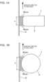
- Figs. 1A and 1B each schematically illustrate a typical embodiment in the case of appying ultrasound to a steel sheet S from an ultrasonic oscillation member 1.
- Fig. 1A illustrates an embodiment in the case of appying ultrasound to the steel sheet S from the ultrasonic oscillation member 1 including a horn 2.
- Fig. 1B illustrates an embodiment when ultrasound is applied to the steel sheet S from the ultrasonic oscillation member 1 including a roll 3 (rotatable roll).
- Figs. 1A and 1B each illustrate a distance of 30 mm between the steel sheet S and the ultrasonic oscillation member 1, the ultrasonic oscillation member 1 applies (imparts) ultrasound to the steel sheet S within a distance of 30 mm.
- the steel sheet S has a thickness of about 1 mm, and the size of the ultrasonic oscillation member 1 (the thickness of the horn 2 and the diameter of the roll 3) is about several tens to about several hundreds of millimeters.
- Fig. 1 is a schematic view, the size of the ultrasonic oscillation member 1 and the distance (30 mm) between the ultrasonic oscillation member 1 and the steel sheet S are reduced in relation to the thickness of the steel sheet S.
- the ultrasonic oscillation member 1 including the roll 3 (rotatable roll) as illustrated in Fig. 1B is preferably used.
- the reasons for this are as follows: In the case where the ultrasonic oscillation member 1 includes the roll 3, dross inclusion is less likely to occur because the roll faces the steel sheet S in a line. Additionally, dross is less likely to be accumulated between the roll and the steel sheet S owing to the rotation of the roll 3.
- the vibration of the ultrasonic transducer is transmitted to the roll 3, and the ultrasonic vibration is imparted from the roll 3 to the steel sheet S.
- the vibration of the ultrasonic transducer is imparted to the roll shaft of the roll 3, and the roll 3 is vibrated by the ultrasonic transducer in the axial direction of the roll or in the radial direction of the roll.
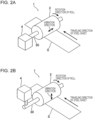
- Figs. 2A and 2B each schematically illustrate a mode of vibration of the roll 3.
- the ultrasonic transducer of an ultrasonic oscillator 4 is mechanically connected or linked to a roll shaft 30 in such a manner that the ultrasonic vibration can be transmitted, so that the vibration of the ultrasonic transducer is transmitted to the roll 3 (roll main body) through the roll shaft 30.
- the roll 3 vibrates ultrasonically in the axial direction of the roll in Fig. 2A
- the roll 3 vibrates ultrasonically in the radial direction of the roll in Fig. 2B .
- the roll 3 can be rotated by a driving device, such as a motor, and may be rotated (forward rotation with respect to the traveling direction of the steel sheet S) in such a manner that the roll surface facing the steel sheet S moves in the same direction as the traveling direction of the steel sheet.
- the roll may be rotated (backward rotation with respect to the traveling direction of the steel sheet S) in such a manner that the roll surface facing the steel sheet S moves in a direction opposite the traveling direction of the steel sheet.
- the peripheral speed of the roll 3 may match the traveling speed of the steel sheet S.
- a mechanism in which the roll 3 is not driven and is rotated by being brought into contact with the steel sheet S may be used.
- the roll shaft 30 may be supported by the arm of a holding unit, and the roll 3 may be held in the bath, similar to a sink roll-supporting mechanism.
- the roll shaft 30 can be supported by bearings on both side walls of a pot, and the roll shaft 30 can be rotated by a drive disposed outside the pot.
- the application of ultrasound to the steel sheet S from the ultrasonic oscillation member 1 including the foregoing roll 3 is less likely to cause dross inclusion to occur because of a small surface of the ultrasonic oscillation member 1 facing the steel sheet S, compared with the ultrasonic horn. Moreover, the dross is less likely to accumulate between the roll 3 and the steel sheet S due to the rotation of the roll 3; this can suppress defects caused by dross inclusion between the ultrasonic oscillation member 1 and the steel sheet S.
- the roll 3 vibrates ultrasonically in the radial direction of the roll and rotates in such a manner that the roll surface facing the steel sheet moves in the same direction as the traveling direction of the steel sheet (forward rotation with respect to the traveling direction of the steel sheet S), as illustrated in Fig. 2A .
- the roll peripheral speed of the roll 3 is the same as the traveling speed of steel sheet S.
- the frequency of the ultrasound applied to the steel sheet is 10 kHz or more. At an ultrasonic frequency of less than 10 kHz, no effect of improving the wettability can be provided. At an ultrasonic frequency of more than 80 kHz, uneven alloying tends to occur, the effect of ultrasonic application is saturated, and an expensive ultrasonic oscillation member is required; thus, an ultrasonic frequency of 80 kHz or less is preferred. From the above perspectives, the ultrasonic frequency is preferably 15 kHz or more, more preferably 18 kHz or more. The ultrasonic frequency is more preferably 40 kHz or less, even more preferably 35 kHz or less. In the alloying treatment, preferably, the ultrasonic frequency and the effective Al concentration in the bath are adjusted to appropriate ranges in such a manner that the alloying treatment temperature T described below is optimized.
- the time for applying the ultrasound is in the range of 0.010 seconds to 0.500 seconds.
- the time for applying the ultrasound is preferably 0.012 seconds or more, more preferably 0.015 seconds or more.
- the time for applying the ultrasound is preferably 0.350 seconds or less, more preferably 0.200 seconds or less.
- the time for applying the ultrasound is the time when the steel sheet lies in the range where the perpendicular distance from the surface of the steel sheet to the ultrasonic oscillation member is within 30 mm.
- the time for applying the ultrasound is the time for the steel sheet S to pass through a range L in each of Figs. 1A and 1B .
- the range L is a portion marked with dots in each figure and is the range (region) where the perpendicular distance from the surface of the steel sheet S to the ultrasonic oscillation member 1 is within 30 mm.
- the time for applying the ultrasound is preferably 0.012 seconds or more and 0.350 seconds or less, more preferably 0.015 seconds or more and 0.200 seconds or less.
- the amplitude of the ultrasonic oscillation member is preferably, but not necessarily, about 1 ⁇ m or more.
- the amplitude is 10 ⁇ m or less. At an amplitude of less than 1 ⁇ m, its control is difficult, and the effect of improving the wettability is apt to be small. At more than 10 ⁇ m, the excessively large amplitude causes damage to the steel sheet.
- the position at which the ultrasound is applied to the steel sheet may be any position between a position at which the immersion of the steel sheet in the hot-dip galvanizing bath is started and a position at which the coating weight adjustment of the steel sheet withdrawn from the hot-dip galvanizing bath is completed.
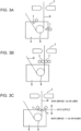
- Figs. 3A to 3C schematically illustrate various embodiments with different positions of the application of ultrasound.
- 5 denotes a hot-dip galvanizing bath
- 6 denotes a sink roll
- 7 denotes gas wiping nozzles for the coating weight adjustment.
- the horn-type ultrasonic oscillation members 1 are used, ultrasound application to one surface of the steel sheet S is performed at a position just below a position where the steel sheet S enters the hot-dip galvanizing bath 5, and ultrasound application to the other surface of the steel sheet S is performed at a position where the steel sheet S is wrapped around the sink roll 6.
- the roll-type ultrasonic oscillation members 1 are used, and ultrasound application to both surfaces of the steel sheet S is performed at a position (same position) where the steel sheet S is withdrawn from the hot-dip galvanizing bath 5.
- Fig. 3A the horn-type ultrasonic oscillation members 1 are used, ultrasound application to one surface of the steel sheet S is performed at a position just below a position where the steel sheet S enters the hot-dip galvanizing bath 5, and ultrasound application to the other surface of the steel sheet S is performed at a position where the steel sheet S is wrapped around the sink roll 6.
- the roll-type ultrasonic oscillation members 1 are used, and ultrasound application to both surfaces of the steel sheet
- the horn-type ultrasonic oscillation members 1 are used, and ultrasound application to both surfaces of the steel sheet S is performed at a position (same position) just below a position where the steel sheet S is withdrawn from the hot-dip galvanizing bath 5.
- ultrasound position just below a position where the steel sheet S is withdrawn from the hot-dip galvanizing bath 5.
- ultrasonic transducers are disposed outside the bath, and the vibrations are transmitted to the ultrasonic oscillation members 1. This is because the ultrasonic transducers, serving as ultrasonic oscillation sources, usually have no heat resistance to withstand the temperature of the bath.
- the position where ultrasound is applied to the steel sheet S is preferably within the range of 1.5 m below the surface of the coating bath (lower level) to 5.0 m above the surface of the coating bath (upper level) (within the range indicated by the arrow in Fig. 3C ) in the height direction with respect to the surface of the coating bath, more preferably within the range of 1.0 m below the surface of the coating bath to 3.0 m above the surface of the coating bath, even more preferably within the range of the surface of the coating bath to 2.0 m above the surface of the coating bath.
- the ultrasonic oscillation members 1 may be disposed at one position or multiple positions. To apply ultrasound to the entire width direction of the steel sheet S, the multiple ultrasonic oscillation members 1 are preferably disposed in the width direction of the steel sheet and the longitudinal direction of the steel sheet. For example, two or more and 40 or less ultrasonic oscillation members 1 having a width of 50 mm or more and 300 mm or less are preferably disposed.
- Ultrasound may be applied to only one surface of the steel sheet S. However, the effect does not extend to the surface of the steel sheet to which no ultrasound is applied; thus, as illustrated in Fig. 3A to 3C , it is preferable to apply ultrasound to both surfaces of the steel sheet, especially to apply ultrasound to both surfaces of the steel sheet at the same position.
- the coating weight adjustment is performed by scraping off a portion of molten zinc adhering to surfaces of the steel sheet withdrawn from the hot-dip galvanizing bath.
- the coating weight (coating weight of the hot-dip galvanized steel sheet) after this adjustment is not particularly limited. An insufficient coating weight results in a decrease in corrosion resistance and makes it difficult to control the coating weight itself. An excessively high coating weight results in a deterioration in the adhesion of coating. Accordingly, usually, the coating weight per surface is preferably in the range of about 25 g/m 2 or more and about 80 g/m 2 or less.
- a method for performing the coating weight adjustment is not particularly limited. Usually, gas wiping is performed as illustrated in Figs. 3A to 3C . The amount of molten zinc scraped off is adjusted by adjusting the gas pressure of the gas wiping and the distance between the gas wiping nozzles and the steel sheet. Thereby, the coating weight adjustment is performed.
- the ultrasonic oscillation member 1 which applies ultrasound to the steel sheet S, may be used as a unit configured to perform the coating weight adjustment (unit configured to scrape molten zinc) to adjust the coating weight.
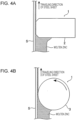
- Figs. 4A and 4B schematically illustrate embodiments in that case.
- Fig. 4A illustrates the case where the ultrasonic oscillation member 1 including the horn 2 is used.
- Fig. 4B illustrates the case where the ultrasonic oscillation member 1 including the roll 3 (rotatable roll) is used.
- the ultrasonic oscillation member 1 applies ultrasound to the steel sheet S and is disposed at a predetermined distance from the steel sheet S to scrape off a portion of molten zinc adhering to the surface of the steel sheet downward, thereby adjusting the coating weight.
- the steel sheet S has a thickness of about 1 mm
- the coated layer has a thickness of about 10 ⁇ m
- the size of the ultrasonic oscillation member 1 (the thickness of the horn 2 and the diameter of the roll 3) is about several tens to about several hundreds of millimeters.
- Figs. 4A and 4B is a schematic view, the thickness of the coated layer is enlarged, and the size of the ultrasonic oscillation member 1 is reduced, in relation to the thickness of the steel sheet S.
- the ultrasonic oscillation member 1 including the roll 3 (rotatable roll) is used as illustrated in Fig. 4B , the roll 3 is rotated (backward rotation with respect to the traveling direction of the steel sheet S) in such a manner that the roll surface facing the steel sheet S moves in a direction opposite the traveling direction of the steel sheet. Thereby, a portion of molten zinc adhering to the surface of the steel sheet is scraped off downward.
- Figs. 4A and 4B each illustrate only one surface of the steel sheet, the same coating weight adjustment is usually performed at the same position on the other surface of the steel sheet.
- the hot-dip galvanized steel sheet that has been subjected to the coating weight adjustment as described above is heated to perform the alloying treatment of the coated layer. If this alloying treatment is not performed, the oxide films (oxides) of Si and Mn formed at the interface between the coated layer and the steel sheet cause a decrease in the adhesion of coating.
- the alloying treatment allows the steel sheet to react with zinc and incorporates the oxide films into the coated layer to improve the adhesion of coating. Even if the oxide films of Si and Mn are formed, the formation of the Fe-Al alloy layer and the alloying reaction proceeds through the gaps in the oxide films.
- the treatment time of the alloying treatment is 10 seconds or more.
- the treatment time is preferably 11 seconds or more, more preferably 12 seconds or more.
- alloying does not proceed sufficiently; thus, the uneven alloying and the coating appearance are poor.
- the treatment time of the alloying treatment is preferably 60 seconds or less, more preferably 50 seconds or less, even more preferably 40 seconds or less.
- alloying proceeds excessively, thereby deteriorating the powdering resistance.
- This alloying treatment is preferably performed at an alloying treatment temperature T (°C) that satisfies the following formula: 25 ⁇ log f + 2 ⁇ 300 ⁇ log 0.12 ⁇ Al + 20 ⁇ T ⁇ 35 ⁇ log f + 2 ⁇ 250 ⁇ log 0.12 ⁇ Al + 150 T ⁇ 570
- T alloying treatment temperature
- [Al] is an effective Al concentration (% by mass) in the hot-dip galvanizing bath
- f is the ultrasonic frequency (kHz) of the ultrasound applied to the steel sheet.
- the application of ultrasound to the steel sheet promotes the supply of Al from the hot-dip galvanizing bath (or molten zinc adhering to the steel sheet) to the steel sheet to form an Fe-Al alloy layer at a gap between the oxide films of Si and Mn formed at the interface between the steel sheet and the coated layer, thereby increasing the alloying temperature.
- the black circle symbols indicate the case where no ultrasound is applied (0 kHz).
- the black circle symbols in Fig. 5 also indicate the alloying treatment temperatures at which rank 1 or 2 (excellent) was obtained when powdering resistance was evaluated in the same manner as in Examples described below (the same applies to the evaluation of "Powdering Resistance” described below) and at which rank 1 (excellent) was obtained when uneven alloying was evaluated in the same manner as in Examples described below (the same applies to the evaluation of "uneven alloying” described below).
- the rhombus symbols in Fig. 5 indicate the case where ultrasound with a frequency of 40 kHz is applied.
- the rhombus symbols in Fig. 5 also indicate the alloying treatment temperatures at which both of the powdering resistance rated as rank 1 or 2 (excellent) and the coating appearance rated as rank 1 (excellent) free from uneven alloying were achieved.
- the appropriate alloying treatment temperature was increased even at the same Al concentration, compared with the case where no ultrasound was applied.
- the formation of the Fe-Al alloy layer is promoted as the ultrasonic frequency increases.
- the appropriate alloying treatment temperature increases.
- the alloying treatment temperature needed increases as the ultrasonic frequency increases. As illustrated in Fig. 5 , the alloying treatment temperature needed decreases as the effective Al concentration in the bath decreases. That is, in order to obtain particularly good powdering resistance and coating appearance, it is preferable to control the ultrasonic frequency and the effective Al concentration in the bath, as well as to precisely control the alloying treatment temperature after the hot-dip coating, i.e., it is preferable to satisfy formula (1) below: 25 ⁇ log f + 2 ⁇ 300 ⁇ log 0.12 ⁇ Al + 20 ⁇ T ⁇ 35 ⁇ log f + 2 ⁇ 250 ⁇ log 0.12 ⁇ Al + 150
- the alloying treatment temperature is preferably 570°C or lower.
- the alloying treatment temperature is higher than 570°C, a retained austenite phase, which is necessary to achieve high ductility, in a steel-sheet microstructure formed during recrystallization annealing (reduction annealing) may decompose into a pearlite phase, and the tempering of a martensite phase, which is necessary to achieve high strength, may occur, thereby possibly failing to achieve sufficient workability (strength-ductility balance).
- the alloying treatment temperature is more preferably 550°C or lower. At lower than 450°C, the progress of alloying is slowed down; thus, 450°C or higher is preferred. More preferably, the alloying treatment temperature is 470°C or higher.
- a heating method used in the alloying treatment is not particularly limited.
- a conventional heating method such as gas heating, induction heating, or electrical heating, may be employed.
- the Fe concentration (degree of alloying) of the hot-dip galvanized layer after the alloying treatment is not particularly limited.
- the Fe concentration (degree of alloying) is preferably about 6% or more by mass and about 15% or less by mass, more preferably 7% or more by mass and 13% or less by mass, even more preferably 8% or more by mass and 12% or less by mass.
- An Fe concentration of less than 6% by mass may result in uneven alloying in portions where an alloying reaction is insufficient and a deterioration in the adhesion of coating.
- An Fe concentration of more than 15% by mass may result in a deterioration in powdering resistance.
- the coating appearance, the adhesion of coating, the powdering resistance, the workability, and the bendability can be evaluated by methods described in the examples.
- the base steel sheet to be subjected to hot-dip galvanization in the present invention is a high-strength steel sheet containing, as solid-solution strengthening elements, Si: 0.1% or more and 2.5% or less and Mn: 1.0% or more and 3.0% or less.
- the tensile strength of the high-strength steel sheet is 440 MPa or more.
- This base steel sheet can be a cold-rolled steel sheet or hot-rolled steel sheet.
- the base steel sheet has a chemical composition containing, as basic components, C: 0.3% or less, Si: 0.1% or more and 2.5% or less, Mn: 1.0% or more and 3.0% or less, P: 0.100% or less, and S: 0.010% or less.
- the base steel sheet can contain one or more selected from Al: 0.01% or more and 1.0% or less, Mo: 0.05% or more and 1.0% or less, Nb: 0.005% or more and 0.05% or less, Ti: 0.005% or more and 0.05% or less, Cu: 0.05% or more and 1.0% or less, Ni: 0.05% or more and 1.0% or less, Cr: 0.01% or more and 0.8% or less, B: 0.0005% or more and 0.005% or less, Sb: 0.001% or more and 0.10% or less, and Sn: 0.001% or more and 0.10% or less, in order to control the balance between the strength and the ductility, etc.
- Al 0.01% or more and 1.0% or less
- Mo 0.05% or more and 1.0% or less
- Nb 0.005% or more and 0.05% or less
- Ti 0.005% or more and 0.05% or less
- Cu 0.05% or more and 1.0% or less
- Cr 0.01%
- Si is an element effective in strengthening the steel to obtain good material properties. At a Si content of less than 0.1%, an expensive alloying element is needed to obtain high strength, which is economically undesirable. A Si content of more than 2.5% results in a higher alloying temperature. This makes it difficult to obtain desired mechanical properties even if the production conditions of the present invention are used. In addition, poor appearance, such as uneven alloying, and poor adhesion of coating are caused. Accordingly, the Si content is 0.1% or more and 2.5% or less.
- ⁇ Mn 1.0% or More and 3.0% or Less
- Mn is an element effective in increasing the strength of steel and needs to be contained in an amount of 1.0% or more in order to achieve good mechanical properties and high strength.
- a Mn content of more than 3.0% may result in deteriorations in weldability and the adhesion of coating, thereby possibly making it difficult to achieve a good balance between the strength and the ductility. Accordingly, the Mn content is 1.0% or more and 3.0% or less.
- a C content of more than 0.3% results in a deterioration in weldability.
- the C content is 0.3% or less.
- C facilitates an improvement in workability through the formation of, for example, a retained austenite phase and a martensite phase in the steel microstructure. Accordingly, the C content is preferably 0.025% or more.
- P is an inevitably contained element; thus, the lower limit is not specified.
- a P content of more than 0.100% may result in a deterioration in weldability. Accordingly, the P content is 0.100% or less.
- S is an inevitably contained element; thus, the lower limit is not specified.
- a S content of more than 0.010% may result in a deterioration in weldability. Accordingly, the S content is 0.010% or less.
- Al is an element effective in suppressing the formation of carbide to promote the formation of retained austenite.
- Al is also an element that is added as a deoxidizing agent in the steelmaking process. To provide these effects, the Al content needs to be 0.01% or more.
- An Al content of more than 1.0% results in more inclusions in the steel sheet to deteriorate the ductility. Accordingly, when Al is added, the Al content is 0.01% or more and 1.0% or less.
- Mo is an element effective in adjusting the strength. At a Mo content of less than 0.05%, however, the effect of strength adjustment is less likely to be provided. A Mo content of more than 1.0% leads to an increase in cost. Accordingly, when Mo is added, the Mo content is 0.05% or more and 1.0% or less.
- Nb is also an element effective in adjusting the strength. At a Nb content of less than 0.005%, however, the effect of strength adjustment is less likely to be provided. A Nb content of more than 0.05% leads to an increase in cost. Accordingly, when Nb is added, the Nb content is 0.005% or more and 0.05% or less.
- Ti is also an element effective in adjusting the strength. At a Ti content of less than 0.005%, however, the effect of strength adjustment is less likely to be provided. At a Ti content of more than 0.05%, the adhesion of coating deteriorates easily. Accordingly, when Ti is added, a Ti content is 0.005% or more and 0.05% or less.
- Cu is effective in promoting the formation of a retained austenite phase. At a Cu content of less than 0.05%, however, the effect of promoting the formation of the retained austenite phase is less likely to be provided. A Cu content of more than 1.0% leads to an increase in cost. Accordingly, when Cu is added, the Cu content is 0.05% or more and 1.0% or less.
- ⁇ Ni 0.05% or More and 1.0% or Less
- Ni is also effective in promoting the formation of the retained austenite phase.
- a Ni content of less than 0.05% however, the effect of promoting the formation of the retained austenite phase is less likely to be provided.
- a Ni content of more than 1.0% leads to an increase in cost. Accordingly, when Ni is added, the Ni content is 0.05% or more and 1.0% or less.
- Cr is an element effective in improving the hardenability. At a Cr content of less than 0.01%, however, the effect of improving the hardenability is less likely to be provided, thereby possibly deteriorating the balance between the strength and the ductility. A Cr content of more than 0.8% leads to an increase in cost. Accordingly, when Cr is added, the Cr content is 0.01% or more and 0.8% or less.
- ⁇ B 0.0005% or More and 0.005% or Less
- B is also an element effective in improving the hardenability. At a B content of less than 0.0005%, however, the effect of improving the hardenability is less likely to be provided. A B content of more than 0.005% results in the promotion of the oxidation of Si on a surface of the steel sheet to lead to poor coating appearance. Accordingly, when B is added, the B content is 0.0005% or more and 0.005% or less.
- ⁇ Sb 0.001% or More and 0.10% or Less
- Sb is an element effective in suppressing, for example, denitrification and deboronization to suppress a decrease in the strength of steel. At an Sb content of less than 0.001%, however, the effect is less likely to be provided. An Sb content of more than 0.10% leads to deteriorations in toughness and cracking resistance in a shear area. Accordingly, when Sb is added, the Sb content is 0.001% or more and 0.10% or less.
- ⁇ Sn 0.001% or More and 0.10% or Less
- Sn is also an element effective in suppressing, for example, denitrification and deboronization to suppress a decrease in the strength of steel. At a Sn content of less than 0.001%, however, the effect is less likely to be provided. A Sn content of more than 0.10% leads to deteriorations in toughness and cracking resistance in a shear area. Accordingly, when Sn is added, the Sn content is 0.001% or more and 0.10% or less.
- the balance other than the basic components and optional additive components described above consists of Fe and incidental impurities.
- a hot-dip galvannealed steel sheet produced in the present invention will be described below.
- This hot-dip galvannealed steel sheet is produced by the production method of the present invention through reduction annealing in an atmosphere having a specific dew-point temperature (dew-point temperature: -40°C or higher and -20°C or lower) as described above, then hot-dip galvanization, and alloying treatment.
- the hot-dip galvannealed layer (hereinafter, referred to as an "alloyed coated layer", for the convenience of description) has an Fe concentration (degree of alloying) of 6% or more by mass and 15% or less by mass. An Fe concentration in the alloyed coated layer of less than 6% by mass may result in uneven alloying in portions where an alloying reaction is insufficient and a deterioration in the adhesion of coating.
- the Fe concentration in the alloyed coated layer can be determined, for example, by dissolving the alloyed coated layer of the coated steel sheet in hydrochloric acid containing an inhibitor and measuring the amounts of Fe and the remaining components, such as Zn, in the hydrochloric acid using ICP.
- the composition of the base steel sheet is as described above, and the amount of internal oxide containing Si oxide and Mn oxide in the base steel sheet (a surface layer portion of the steel sheet) is 0.05 g/m 2 or less (in terms of oxygen O), which is a sufficiently low level.
- the internal oxides of Si and Mn are present in the surface layer portion of the steel sheet, these internal oxides act as starting points of cracks to easily deteriorate the bendability.
- the amount of internal oxide is 0.05 g/m 2 or less (in terms of oxygen O)
- good bendability is obtained.
- the oxides of Si and Mn formed during reduction annealing are incorporated into the coated layer during the alloying treatment together with the oxides on the surface of the steel sheet.
- the oxides present further in the inner side of the steel sheet are left in the steel sheet as "internal oxides".
- the amount of internal oxide can be measured by measuring the amount of oxygen in steel of the surface layer portion of the base steel sheet (base iron) after removal of the coated layer.
- the amount of oxygen in steel can be measured by an "impulse furnace fusion-infrared absorption method".
- To obtain the amount of internal oxide in the surface layer portion of the steel sheet just below the coated layer it is necessary to subtract the amount of oxygen contained in the base material itself from the measured amount of oxygen in the steel.
- the surface layer portions on the front and back sides of a sample whose coated layers have been removed are mechanically polished to a depth of 100 ⁇ m or more, and the amount of oxygen in the steel of the resulting sample is separately measured in the same manner as above.
- the amount of oxygen in the steel of the surface layer portions of the steel sheet is calculated. This is converted into the amount of internal oxide per unit area and defined as the amount of internal oxide in the surface layer portions of the steel sheet (in terms of oxygen O, g/m 2 ).
- the coated steel sheet only needs to be immersed in a solution mixture of 195 cc of an aqueous solution of 20% by mass NaOH-10% by mass triethanolamine and 7 cc of a 35% by mass hydrogen peroxide solution. This enables removal of only the coated layer.
- the hot-dip galvannealed steel sheet produced in the present invention is subjected to reduction annealing in an atmosphere whose dew-point temperature is controlled within the predetermined range described above, so that the Si and Mn dissolved in each surface layer portion of the steel sheet are oxidized on the surface.
- the formation of Si- and Mn-deficient layer in the surface layer portion of the steel sheet softens the microstructure of the surface layer of the steel sheet to obtain good bendability.
- the Si and Mn oxides formed in the surface layer portion of the steel sheet during the reduction annealing are partially incorporated into the coated layer during the alloying treatment; thus, the coated layer (hot-dip galvannealed layer) contains the Si oxide and the Mn oxide.
- the optimizations of the chemical composition of the base steel sheet and the reduction annealing conditions result in a reduction in the overall amount of oxides and the formation of the Si- and Mn-deficient layer in the surface layer portion of the steel sheet.
- the product (M Si ⁇ M Mn ) of the total amount of Si oxide M Si (in terms of metal Si, g/m 2 ) and the total amount of Mn oxide M Mn (in terms of metal Mn, g/m 2 ) present in the hot-dip galvannealed layer and at the interface between the hot-dip galvannealed layer and the steel sheet satisfies formula (3): 0.0004 ⁇ M Si ⁇ M Mn ⁇ 0.0450 .
- M Si ⁇ M Mn is less than 0.0004, the Si- and Mn-deficient layer is not appropriately formed in the surface layer portion of the steel sheet.
- the microstructure of the surface layer portion of the steel sheet is close to a single martensite phase and has high hardness, deteriorating the bendability.
- M Si ⁇ M Mn is more than 0.0450, the absolute amount of Si and Mn oxides formed in the surface layer portion of the steel sheet is increased. Even if the Si and Mn oxides are partially incorporated into the coated layer, the remaining Si and Mn oxides deteriorate the adhesion of coating. From the above point of view, M Si ⁇ M Mn is more preferably in the range of 0.0010 or more.
- M Si ⁇ M Mn is more preferably in the range of 0.0350 or less, even more preferably 0.0300 or less.
- the above-mentioned hot-dip galvannealed steel sheet is excellent in coating appearance, the adhesion of coating, and bendability. Moreover, the hot-dip galvannealed steel sheet is also excellent in powdering resistance and workability.
- the amount of Si oxide (M Si ) and the amount of Mn oxide (M Mn ) present in the coated layer and at the interface between the coated layer and the steel sheet can be determined, for example, as follows:
- the coated steel sheet is immersed in a solution mixture of 195 cc of an aqueous solution of 20% by mass NaOH-10% by mass triethanolamine and 7 cc of a 35% by mass hydrogen peroxide solution to dissolve the coated layer.
- the solution is filtered, and then the amount of Si and the amount of Mn in the solution are measured by ICP emission spectroscopy and converted into the amount of Si per unit area M 1 Si (in terms of metal Si, g/m 2 ) and the amount of Mn per unit area M 1 Mn (in terms of metal Mn, g/m 2 ).
- the coated steel sheet is immersed in hydrofluoric acid containing an inhibitor to dissolve the coated layer (oxide present at the interface between the coated layer and the steel sheet is also dissolved).
- the solution is filtered, and then the amount of Si and the amount of Mn in the solution are measured by ICP emission spectroscopy and converted into the amount of Si per unit area (M 2 Si ) (in terms of metal Si, g/m 2 ) and the amount of Mn per unit area (M 2 Mn ) (in terms of metal Mn, g/m 2 ) .
- the amount of Si oxide (M Si ) and the amount of Mn oxide (M Mn ) are determined by the following formulae. That is, as M 1 Si and M 1 Mn , the amount of Si and the amount of Mn, which are dissolved in the coated layer (and are non-oxides), are measured.
- M Si and M 2 Mn the total amount of Si and the total amount of Mn, which are present in the coated layer and at the interface between the coated layer and the steel sheet (and include oxides and non-oxides) are measured.
- Cast slabs of steels that were obtained by steelmaking and that had chemical compositions given in Table 1 were subjected to hot rolling, pickling, and then cold rolling to produce cold-rolled steel sheets having a thickness of 1.2 mm. These cold-rolled steel sheets were used as base steel sheets, and hot-dip galvannealed steel sheets were produced as follows: In a CGL equipped with an ART-type annealing furnace, the cold-rolled steel sheets were subjected to reduction annealing in a N 2 -10% H 2 atmosphere (held at annealing temperatures given in Tables 2 and 3 for 120 seconds) and then immersion in a hot-dip galvanizing bath (coating bath temperature: 460°C) to perform hot-dip galvanization.
- each of the steel sheets was withdrawn from the coating bath, and then the coating weight (the weight of coating) per side was adjusted to about 50 g/m 2 by gas wiping. Subsequently, alloying treatment was performed. Ultrasound was applied to both surfaces of the steel sheet (at the same position on both sides of the steel sheet) with ultrasonic oscillation members during a period from the time the steel sheet was immersed in the coating bath to the time the coating weight of the steel sheet withdrawn from the coating bath was adjusted by the gas wiping. As the ultrasonic oscillation members, horns or rolls as illustrated in Fig. 1 were used, and the amplitude was 5 ⁇ m.
- Each of the rolls used for the ultrasonic oscillation members was the roll with the vibration mode illustrated in Fig. 2B and rotationally driven in such a manner that the roll surface facing the steel sheet moved in the same direction as the traveling direction of the steel sheet (forward-rotation drive with respect to the traveling direction of the steel sheet).
- the peripheral speed of the roll was the same as the strip speed.
- the ultrasound application and/or the alloying treatment was not performed.
- the coating appearance was evaluated, and the adhesion of coating, the steel sheet workability (tensile properties), the bendability, and the powdering resistance were investigated. Their measurement and evaluation methods are described below.
- each steel sheet was inspected for the presence of bare spots, uneven alloying, and dross adhesion defects.
- a steel sheet measuring 1,000 mm ⁇ 1,000 mm was taken from each of the equally divided 10 parts of one coil to prepare a total of 10 steel sheet samples.
- a steel sheet in which no defects were observed in any of the steel sheet samples was rated as excellent (A: rank 1).
- a steel sheet in which defects were observed in one or two steel sheet samples was rated as good (B: rank 2).
- a steel sheet in which defects were found in three or more steel sheet samples was rated as poor (C: rank 3).
- a steel sheet that was not rated as C in terms of all of the bare spots, the uneven alloying, and the dross adhesion defects was evaluated as having excellent coating appearance.
- the bare spots are defects that are visually recognized as black dots, and when surface or crosssectional observation and analysis are conducted by SEM-EDX, Zn adhesion is not observed, and the exposure of base iron can be observed.
- the uneven alloying is a defect in which unevenness can be visually observed because of the difference in the color of the coating, and when analysis is performed by SEM-EDX or ICP, the coated layer has a portion where the Fe concentration differs by 1% or more, compared with the surrounding area.
- the dross adhesion defects are defects in which point or line depressions or bumps can be visually observed on the coating, and when the cross section of the defective area is analyzed by SEM-EDX, the adhesion of dross clearly different from the zinc coating or base iron is observed.
- top dross is mainly composed of Fe 2 Al 5
- bottom dross is mainly composed of FeZn 7 .
- the dross may have a composition deviating from the equilibrium composition and may contain Al oxides, Fe oxides, and Zn oxides.
- a ball impact test was performed on test specimens taken from the coated steel sheets under ball impact conditions: ball weight: 1,000 g and 3,000 g; and ball drop height: 100 cm.
- the processed portions were peeled off with tapes, and the presence or absence of peeling of the coated layer was visually determined and evaluated as follows. In this evaluation, A or B was evaluated as excellent adhesion of coating.
- Adhesive cellophane tapes were attached to test specimens taken from the coated steel sheets. Each of the tape-attached portions was subjected to 90°-bending and bending back. An adhesive cellophane tape with a width of 24 mm was pressed against the inside of the bent portion (compressed side) parallel to the bent portion and then was peeled off. The amount of zinc adhered to a 40-mm-long portion of the adhesive cellophane tape was measured as Zn counts by X-ray fluorescence. The Zn counts were converted into the amount (X-ray fluorescence counts) per unit length (1 m).
- a steel sheet rated rank 1 or 2 was evaluated as excellent (A)
- a steel sheet rated rank 3 was evaluated as good (B)
- a steel sheet rated rank 4 or 5 was evaluated as poor (C).
- a or B was evaluated as excellent powdering resistance.
- a JIS No. 5 test specimen taken from each of the coated steel sheets was used.
- the tensile properties were measured in accordance with JIS Z2241 using the rolling direction as the tensile direction, and TS ⁇ EL was determined.
- a steel sheet with TS ⁇ EL > 12,000 was evaluated as having excellent steel sheet workability.
- a strip-like test specimen with a width of 30 mm and a length of 100 mm was taken from each of the coated steel sheets in such a manner that a direction parallel to the rolling direction of the steel sheet was the axial direction of a bend test.
- the bend test was performed with the test specimen in accordance with JIS Z2248.
- a 90° V-bending test was performed under the conditions as follows: a pressing load of 100 kN, and a press-holding time of 5 seconds.
- a ridge portion at the apex of the resulting bend was observed using a microscope ("RH-2000", available from Hirox Co., Ltd.) with a magnification of 40 ⁇ .
- a bend radius when no cracks with a crack length of 200 ⁇ m or more were observed was defined as the minimum bend radius (R).
- the value (R/t) was obtained by dividing R by the sheet thickness (t).
- the bendability was evaluated as follows: In this evaluation, A or B was evaluated as excellent bendability.
- the high-strength hot-dip galvanized steel sheets of the examples have beautiful coating appearance free from bare spots, dross adhesion defects, or uneven alloying, and also have excellent adhesion of coating.
- the steel sheets are also excellent in steel sheet workability, powdering resistance, and bendability.
- a method for producing a high-strength hot-dip galvanized steel sheet including, as a base material, a high-strength steel sheet containing Si and Mn, in which the hot-dip galvanized steel sheet having excellent adhesion of coating and beautiful coating appearance free from bare spots can be stably produced.
- a method for producing a high-strength hot-dip galvanized steel sheet in which the hot-dip galvanized steel sheet excellent in coating appearance, adhesion of coating, powdering resistance, workability, and bendability can be stably produced by optimizations of annealing conditions, alloying treatment conditions, and so forth.
Landscapes
- Chemical & Material Sciences (AREA)
- Engineering & Computer Science (AREA)
- Organic Chemistry (AREA)
- Materials Engineering (AREA)
- Mechanical Engineering (AREA)
- Metallurgy (AREA)
- Chemical Kinetics & Catalysis (AREA)
- Physics & Mathematics (AREA)
- Thermal Sciences (AREA)
- Crystallography & Structural Chemistry (AREA)
- Oil, Petroleum & Natural Gas (AREA)
- Inorganic Chemistry (AREA)
- Coating With Molten Metal (AREA)
- Heat Treatment Of Sheet Steel (AREA)
Claims (11)
- Verfahren zur Herstellung eines hochfesten feuerverzinkten Stahlblechs mit einer Zugfestigkeit von 440 MPa oder mehr, wobei das Verfahren in einer Durchlaufverzinkungsanlage mit einer Bandgeschwindigkeit von 60 mpm oder mehr und 150 mpm oder weniger durchgeführt wird, wobei das Verfahren umfasst:Unterziehen eines Stahlblechs einem Rekristallisationsglühen, wobei das Stahlblech eine chemische Zusammensetzung aufweist, die, bezogen auf Masseprozent, Si: 0,1 % oder mehr und 2,5 % oder weniger, Mn: 1,0 % oder mehr und 3,0 % oder weniger, C: 0,3 % oder weniger, P: 0,100 % oder weniger und S: 0,010 % oder weniger und optional eines oder zwei oder mehr, ausgewählt aus Al: 0,01 % oder mehr und 1,0 % oder weniger, Mo: 0,05 % oder mehr und 1,0 % oder weniger, Nb: 0,005 % oder mehr und 0,05 % oder weniger, Ti: 0,005 % oder mehr und 0,05 % oder weniger, Cu: 0,05 % oder mehr und 1,0 % oder weniger, Ni: 0,05 % oder mehr und 1,0 % oder weniger, Cr: 0,01 % oder mehr und 0,8 % oder weniger, B: 0,0005 % oder mehr und 0,005 % oder weniger, Sb: 0,001 % oder mehr und 0,10 % oder weniger und Sn: 0,001 % oder mehr und 0,10 % oder weniger, enthält, wobei der Rest Fe und zufällige Verunreinigungen ist, dann Unterziehen des Stahlblechs einem Eintauchen in ein Feuerverzinkungsbad mit einer effektiven Al-Konzentration von 0,07 Masse-% oder mehr und 0,170 Masse-% oder weniger zur Durchführung einer Feuerverzinkung, wobei die effektive Al-Konzentration in dem Bad ein Wert ist, der durch Subtrahieren der Fe-Konzentration im Bad von der Al-Konzentration im Bad erhalten wird, anschließendes Unterziehen des Stahlblechs, das dem Feuerverzinkungsbad entnommen wurde, einer Beschichtungsgewichtseinstellung,Anwenden von Ultraschall mit einer Frequenz von 10 kHz oder mehr auf das Stahlblech ausgehend von einem Ultraschallschwingungselement mit einer Amplitude von 10 µm oder weniger für 0,010 Sekunden oder mehr und 0,500 Sekunden oder weniger während eines Zeitraums vom Beginn des Eintauchens bis zum Ende der Beschichtungsgewichtseinstellung, wobei das Ultraschallschwingungselement in Kontakt mit geschmolzenem Zink steht und in einem Abstand von 0 mm oder mehr und 30 mm oder weniger vom Stahlblech angeordnet ist, wobei die Zeit der Ultraschallanwendung die Zeit ist, während der das Stahlblech in dem Bereich liegt, in dem der senkrechte Abstand von der Oberfläche des Stahlblechs zum Ultraschallschwingungselement innerhalb von 30 mm liegt, undUnterziehen der feuerverzinkten Schicht des Stahlblechs nach der Beschichtungsgewichtseinstellung einer Legierungsbehandlung für 10 Sekunden oder mehr.
- Verfahren zur Herstellung eines hochfesten feuerverzinkten Stahlblechs gemäß Anspruch 1, wobei der auf das Stahlblech angewandte Ultraschall eine Frequenz von 80 kHz oder weniger aufweist.
- Verfahren zur Herstellung eines hochfesten feuerverzinkten Stahlblechs gemäß Anspruch 1 oder 2, wobei die feuerverzinkte Schicht der Legierungsbehandlung für 10 Sekunden oder mehr und 60 Sekunden oder weniger unterzogen wird.
- Verfahren zur Herstellung eines hochfesten feuerverzinkten Stahlblechs gemäß einem der Ansprüche 1 bis 3, wobei die Legierungsbehandlung derart durchgeführt wird, dass die feuerverzinkte Schicht eine Fe-Konzentration von 6 Masse-% oder mehr und 15 Masse-% oder weniger aufweist.
- Verfahren zur Herstellung eines hochfesten feuerverzinkten Stahlblechs gemäß einem der Ansprüche 1 bis 4, wobei der Ultraschall auf das Stahlblech ausgehend von dem Ultraschallschwingungselement an einer Stelle in einem Bereich in Höhenrichtung in Bezug auf eine Oberfläche des Feuerverzinkungsbads von 1,5 m unter der Oberfläche des Feuerverzinkungsbads bis 5,0 m über der Oberfläche des Feuerverzinkungsbads angewandt wird.
- Verfahren zur Herstellung eines hochfesten feuerverzinkten Stahlblechs gemäß einem der Ansprüche 1 bis 5, wobei das Rekristallisationsglühen in einer Atmosphäre mit einer Taupunkttemperatur von -40°C oder höher bis -20°C oder niedriger durchgeführt wird.
- Verfahren zur Herstellung eines hochfesten feuerverzinkten Stahlblechs gemäß einem der Ansprüche 1 bis 6, wobei das Ultraschallschwingungselement eine drehbare Walze einschließt.
- Verfahren zur Herstellung eines hochfesten feuerverzinkten Stahlblechs gemäß Anspruch 7, wobei die Walze in dem Ultraschallschwingungselement durch den Ultraschall in einer radialen Richtung der Walze vibriert und sich derart dreht, dass sich eine Walzenoberfläche, die dem Stahlblech gegenüberliegt, in dieselbe Richtung wie eine Laufrichtung des Stahlblechs bewegt.
- Verfahren zur Herstellung eines hochfesten feuerverzinkten Stahlblechs gemäß einem der Ansprüche 1 bis 8, wobei die Beschichtungsgewichtseinstellung durch Abstreichen von geschmolzenem Zink, der an der Oberfläche des Stahlblechs haftet, mit dem Ultraschallschwingungselement durchgeführt wird, während der Ultraschall auf das Stahlblech, das dem Feuerverzinkungsbad entnommenen wurde, mit dem Ultraschallschwingungselement angewandt wird.
- Verfahren zur Herstellung eines hochfesten feuerverzinkten Stahlblechs gemäß einem der Ansprüche 1 bis 9, wobei die Legierungsbehandlung bei einer Legierungsbehandlungstemperatur T in °C durchgeführt wird, die die nachstehenden Formeln (1) und (2) erfüllt:

 worin [Al] eine effektive Al-Konzentration in Masse-% in dem Feuerverzinkungsbad ist undf die Ultraschallfrequenz in kHz des auf das Stahlblech angewandten Ultraschalls ist.
 - Hochfestes feuerverzinktes Stahlblech mit einer Zugfestigkeit von 440 MPa oder mehr, umfassend:eine feuerverzinkte und danach wärmebehandelte Schicht auf einer Oberfläche eines Stahlblechs, wobei das Stahlblech eine chemische Zusammensetzung aufweist, die, bezogen auf Masseprozent, Si: 0,1 % oder mehr und 2,5 % oder weniger, Mn: 1,0 % oder mehr und 3,0 % oder weniger, C: 0,3 % oder weniger, P: 0,100 % oder weniger und S: 0,010 % oder weniger und optional eines oder zwei oder mehr, ausgewählt aus Al: 0,01 % oder mehr und 1,0 % oder weniger, Mo: 0,05 % oder mehr und 1,0 % oder weniger, Nb: 0,005 % oder mehr und 0,05 % oder weniger, Ti: 0,005 % oder mehr und 0,05 % oder weniger, Cu: 0,05 % oder mehr und 1,0 % oder weniger, Ni: 0,05 % oder mehr und 1,0 % oder weniger, Cr: 0,01 % oder mehr und 0,8 % oder weniger, B: 0,0005 % oder mehr und 0,005 % oder weniger, Sb: 0,001 % oder mehr und 0,10 % oder weniger und Sn: 0,001 % oder mehr und 0,10 % oder weniger, enthält, wobei der Rest Fe und zufällige Verunreinigungen ist,wobei die feuerverzinkte und danach wärmebehandelte Schicht eine Fe-Konzentration von 6 Masse-% oder mehr und 15 Masse-% oder weniger aufweist,eine Menge eines inneren Oxids, das in dem Stahlblech enthalten ist, bezogen auf Sauerstoff, 0,05 g/m2 oder weniger beträgt undeine Gesamtmenge an Si-Oxid MSi in g/m2, bezogen auf das Metall Si, und eine Gesamtmenge an Mn-Oxid MMn in g/m2, bezogen auf das Metall Mn, die in der feuerverzinkten und danach wärmebehandelten Schicht und an einer Grenzfläche zwischen der feuerverzinkten und danach wärmebehandelten Schicht und dem Stahlblech vorhanden sind, Formel (3) erfüllen:
 wobei die Menge des inneren Oxids und die Gesamtmenge an Si- und Mn-Oxiden gemäß dem in der Beschreibung beschriebenen Verfahren gemessen werden.
Applications Claiming Priority (2)
| Application Number | Priority Date | Filing Date | Title |
|---|---|---|---|
| JP2019055704A JP6822506B2 (ja) | 2019-03-22 | 2019-03-22 | 高強度溶融亜鉛めっき鋼板の製造方法 |
| PCT/JP2020/011076 WO2020195946A1 (ja) | 2019-03-22 | 2020-03-13 | 高強度溶融亜鉛めっき鋼板及びその製造方法 |
Publications (3)
| Publication Number | Publication Date |
|---|---|
| EP3907304A1 EP3907304A1 (de) | 2021-11-10 |
| EP3907304A4 EP3907304A4 (de) | 2022-03-16 |
| EP3907304B1 true EP3907304B1 (de) | 2024-02-21 |
Family
ID=72558061
Family Applications (1)
| Application Number | Title | Priority Date | Filing Date |
|---|---|---|---|
| EP20778920.7A Active EP3907304B1 (de) | 2019-03-22 | 2020-03-13 | Hochfestes feuerverzinktes stahlblech und verfahren zur herstellung davon |
Country Status (4)
| Country | Link |
|---|---|
| EP (1) | EP3907304B1 (de) |
| JP (1) | JP6822506B2 (de) |
| MX (1) | MX2021011410A (de) |
| WO (1) | WO2020195946A1 (de) |
Cited By (2)
| Publication number | Priority date | Publication date | Assignee | Title |
|---|---|---|---|---|
| EP4357467A4 (de) * | 2021-07-14 | 2024-10-16 | JFE Steel Corporation | Dehydrierungsvorrichtung, system zur herstellung von stahlblech und verfahren zur herstellung von stahlblech |
| EP4361295A4 (de) * | 2021-07-14 | 2024-10-16 | JFE Steel Corporation | Vorrichtung zum kontinuierlichen glühen, vorrichtung zum kontinuierlichen feuerverzinken und verfahren zur herstellung von stahlblech |
Families Citing this family (1)
| Publication number | Priority date | Publication date | Assignee | Title |
|---|---|---|---|---|
| CN115466916B (zh) * | 2022-09-20 | 2023-08-01 | 哈尔滨工业大学(威海) | 一种超声镀锌装置及其镀锌工艺 |
Family Cites Families (10)
| Publication number | Priority date | Publication date | Assignee | Title |
|---|---|---|---|---|
| JPS5322126A (en) | 1976-08-12 | 1978-03-01 | Nippon Steel Corp | Molten metal plating method |
| JPS55100969A (en) * | 1979-01-23 | 1980-08-01 | Asahi Glass Co Ltd | Manufacture of hot galvanized metal plate |
| JPS5723053A (en) | 1980-07-14 | 1982-02-06 | Asahi Glass Co Ltd | Method for plating steel material with molten metal |
| JPH02125850A (ja) * | 1988-11-02 | 1990-05-14 | Kawasaki Steel Corp | 連続溶融亜鉛めっき方法 |
| JPH03158449A (ja) * | 1989-11-15 | 1991-07-08 | Sumitomo Metal Ind Ltd | 合金化溶融亜鉛めっき鋼板の製造方法 |
| JP2000064020A (ja) * | 1998-08-21 | 2000-02-29 | Ajikawa Tekko Kensetsu Kk | 溶融Al−Zn合金めっき方法 |
| JP2001164352A (ja) * | 1999-12-10 | 2001-06-19 | Hitachi Cable Ltd | 溶融めっき複合線の製造方法 |
| JP4238153B2 (ja) * | 2004-02-02 | 2009-03-11 | 新日本製鐵株式会社 | 均一外観性に優れた高強度電気亜鉛めっき鋼板およびその製造方法 |
| KR20140096811A (ko) * | 2013-01-29 | 2014-08-06 | 주식회사 정금중공업 | 용융아연도금방법 |
| JP5920249B2 (ja) * | 2013-03-05 | 2016-05-18 | Jfeスチール株式会社 | めっき密着性に優れた高強度溶融亜鉛めっき鋼板およびその製造方法 |
-
2019
- 2019-03-22 JP JP2019055704A patent/JP6822506B2/ja active Active
-
2020
- 2020-03-13 WO PCT/JP2020/011076 patent/WO2020195946A1/ja not_active Ceased
- 2020-03-13 EP EP20778920.7A patent/EP3907304B1/de active Active
- 2020-03-13 MX MX2021011410A patent/MX2021011410A/es unknown
Cited By (2)
| Publication number | Priority date | Publication date | Assignee | Title |
|---|---|---|---|---|
| EP4357467A4 (de) * | 2021-07-14 | 2024-10-16 | JFE Steel Corporation | Dehydrierungsvorrichtung, system zur herstellung von stahlblech und verfahren zur herstellung von stahlblech |
| EP4361295A4 (de) * | 2021-07-14 | 2024-10-16 | JFE Steel Corporation | Vorrichtung zum kontinuierlichen glühen, vorrichtung zum kontinuierlichen feuerverzinken und verfahren zur herstellung von stahlblech |
Also Published As
| Publication number | Publication date |
|---|---|
| MX2021011410A (es) | 2021-10-13 |
| EP3907304A1 (de) | 2021-11-10 |
| JP6822506B2 (ja) | 2021-01-27 |
| EP3907304A4 (de) | 2022-03-16 |
| JP2020153003A (ja) | 2020-09-24 |
| WO2020195946A1 (ja) | 2020-10-01 |
Similar Documents
| Publication | Publication Date | Title |
|---|---|---|
| JP4943558B2 (ja) | 高強度溶融亜鉛めっき鋼板及びその製造方法 | |
| RU2567960C1 (ru) | Высокопрочный гальванизированный горячим погружением стальной лист | |
| CN103228812B (zh) | 热浸镀Al-Zn系钢板及其制造方法 | |
| RU2572901C2 (ru) | Отожженный слой гальванического покрытия и снабженный таким покрытием стальной лист и способ его получения | |
| CN105283573B (zh) | 热冲压成形体及热冲压成形体的制造方法 | |
| EP2918696B1 (de) | Legiertes schmelztauchgalvanisiertes stahlblech und verfahren zur herstellung davon | |
| EP1980638A1 (de) | Hochfestes blech aus feuerverzinktem stahl mit hervorragender formbarkeit und plattierbarkeit, hochfestes blech aus legiertem feuerverzinktem stahl und verfahren und vorrichtung zur herstellung davon | |
| EP2843077A1 (de) | Verfahren zur herstellung eines galvanisierten stahlblechs für heissprägung, legiertes feuerverzinktes galvanisiertes stahlblech für heissprägung und verfahren zur herstellung davon sowie heissgeprägte komponente | |
| JP6222401B2 (ja) | 高強度溶融亜鉛めっき鋼板の製造方法、高強度溶融亜鉛めっき鋼板用熱延鋼板の製造方法、高強度溶融亜鉛めっき鋼板用冷延鋼板の製造方法、および高強度溶融亜鉛めっき鋼板 | |
| KR101679159B1 (ko) | 용융 아연 도금 강판 | |
| JP5417797B2 (ja) | 高強度溶融亜鉛系めっき鋼板およびその製造方法 | |
| JP6086162B2 (ja) | 高強度溶融亜鉛めっき鋼板の製造方法 | |
| JP5513216B2 (ja) | 合金化溶融亜鉛めっき鋼板の製造方法 | |
| CN103827341A (zh) | 热浸镀锌钢板及其制造方法 | |
| KR20150133708A (ko) | 도금 밀착성이 우수한 용융 아연계 도금 강판 및 그 제조 방법 | |
| EP3498876B1 (de) | Kaltgewalztes hochfestes stahlblech und dessen herstellungsverfahren | |
| EP3907304B1 (de) | Hochfestes feuerverzinktes stahlblech und verfahren zur herstellung davon | |
| TW201319267A (zh) | 合金化熔融鍍鋅鋼板 | |
| JP7044998B2 (ja) | 溶融Zn-Al系めっき鋼板、およびその製造方法 | |
| JP5478804B2 (ja) | 表面外観及びめっき密着性に優れた合金化溶融亜鉛めっき鋼板 | |
| JP6171872B2 (ja) | ホットスタンプ鋼材の製造方法、ホットスタンプ用鋼板の製造方法及びホットスタンプ用鋼板 | |
| JP3661559B2 (ja) | 加工性とめっき密着性に優れた合金化溶融亜鉛めっき高張力鋼板とその製造方法 | |
| JP5092858B2 (ja) | 溶融亜鉛めっき用鋼板及び合金化溶融亜鉛めっき鋼板 | |
| CN116635563A (zh) | 表面质量和点焊性优异的高强度热浸镀锌钢板及其制造方法 | |
| JP2009191338A (ja) | 表面外観およびめっき密着性に優れた合金化溶融亜鉛めっき鋼板およびその製造方法 |
Legal Events
| Date | Code | Title | Description |
|---|---|---|---|
| STAA | Information on the status of an ep patent application or granted ep patent |
Free format text: STATUS: THE INTERNATIONAL PUBLICATION HAS BEEN MADE |
|
| PUAI | Public reference made under article 153(3) epc to a published international application that has entered the european phase |
Free format text: ORIGINAL CODE: 0009012 |
|
| STAA | Information on the status of an ep patent application or granted ep patent |
Free format text: STATUS: REQUEST FOR EXAMINATION WAS MADE |
|
| 17P | Request for examination filed |
Effective date: 20210804 |
|
| AK | Designated contracting states |
Kind code of ref document: A1 Designated state(s): AL AT BE BG CH CY CZ DE DK EE ES FI FR GB GR HR HU IE IS IT LI LT LU LV MC MK MT NL NO PL PT RO RS SE SI SK SM TR |
|
| A4 | Supplementary search report drawn up and despatched |
Effective date: 20220214 |
|
| DAV | Request for validation of the european patent (deleted) | ||
| DAX | Request for extension of the european patent (deleted) | ||
| GRAP | Despatch of communication of intention to grant a patent |
Free format text: ORIGINAL CODE: EPIDOSNIGR1 |
|
| STAA | Information on the status of an ep patent application or granted ep patent |
Free format text: STATUS: GRANT OF PATENT IS INTENDED |
|
| RIC1 | Information provided on ipc code assigned before grant |
Ipc: C22C 38/22 20060101ALI20230328BHEP Ipc: C22C 38/38 20060101ALI20230328BHEP Ipc: C22C 38/32 20060101ALI20230328BHEP Ipc: C22C 38/28 20060101ALI20230328BHEP Ipc: C22C 38/26 20060101ALI20230328BHEP Ipc: C22C 38/18 20060101ALI20230328BHEP Ipc: C22C 38/16 20060101ALI20230328BHEP Ipc: C22C 38/12 20060101ALI20230328BHEP Ipc: C22C 38/08 20060101ALI20230328BHEP Ipc: C22C 38/02 20060101ALI20230328BHEP Ipc: B32B 15/01 20060101ALI20230328BHEP Ipc: C23C 28/00 20060101ALI20230328BHEP Ipc: C23C 2/02 20060101ALI20230328BHEP Ipc: C23C 2/40 20060101ALI20230328BHEP Ipc: C23C 2/32 20060101ALI20230328BHEP Ipc: C23C 2/28 20060101ALI20230328BHEP Ipc: C23C 2/06 20060101ALI20230328BHEP Ipc: C22C 38/60 20060101ALI20230328BHEP Ipc: C22C 38/04 20060101ALI20230328BHEP Ipc: C22C 18/00 20060101ALI20230328BHEP Ipc: C21D 9/46 20060101AFI20230328BHEP |
|
| INTG | Intention to grant announced |
Effective date: 20230412 |
|
| RIN1 | Information on inventor provided before grant (corrected) |
Inventor name: SUZUKI, YOSHITSUGU Inventor name: OKUMURA, YUSUKE |
|
| GRAJ | Information related to disapproval of communication of intention to grant by the applicant or resumption of examination proceedings by the epo deleted |
Free format text: ORIGINAL CODE: EPIDOSDIGR1 |
|
| STAA | Information on the status of an ep patent application or granted ep patent |
Free format text: STATUS: REQUEST FOR EXAMINATION WAS MADE |
|
| INTC | Intention to grant announced (deleted) | ||
| GRAP | Despatch of communication of intention to grant a patent |
Free format text: ORIGINAL CODE: EPIDOSNIGR1 |
|
| STAA | Information on the status of an ep patent application or granted ep patent |
Free format text: STATUS: GRANT OF PATENT IS INTENDED |
|
| INTG | Intention to grant announced |
Effective date: 20231006 |
|
| GRAS | Grant fee paid |
Free format text: ORIGINAL CODE: EPIDOSNIGR3 |
|
| GRAA | (expected) grant |
Free format text: ORIGINAL CODE: 0009210 |
|
| STAA | Information on the status of an ep patent application or granted ep patent |
Free format text: STATUS: THE PATENT HAS BEEN GRANTED |
|
| AK | Designated contracting states |
Kind code of ref document: B1 Designated state(s): AL AT BE BG CH CY CZ DE DK EE ES FI FR GB GR HR HU IE IS IT LI LT LU LV MC MK MT NL NO PL PT RO RS SE SI SK SM TR |
|
| REG | Reference to a national code |
Ref country code: GB Ref legal event code: FG4D |
|
| REG | Reference to a national code |
Ref country code: CH Ref legal event code: EP |
|
| REG | Reference to a national code |
Ref country code: DE Ref legal event code: R096 Ref document number: 602020026110 Country of ref document: DE |
|
| REG | Reference to a national code |
Ref country code: IE Ref legal event code: FG4D |
|
| REG | Reference to a national code |
Ref country code: LT Ref legal event code: MG9D |
|
| REG | Reference to a national code |
Ref country code: NL Ref legal event code: MP Effective date: 20240221 |
|
| PG25 | Lapsed in a contracting state [announced via postgrant information from national office to epo] |
Ref country code: IS Free format text: LAPSE BECAUSE OF FAILURE TO SUBMIT A TRANSLATION OF THE DESCRIPTION OR TO PAY THE FEE WITHIN THE PRESCRIBED TIME-LIMIT Effective date: 20240621 |
|
| PG25 | Lapsed in a contracting state [announced via postgrant information from national office to epo] |
Ref country code: LT Free format text: LAPSE BECAUSE OF FAILURE TO SUBMIT A TRANSLATION OF THE DESCRIPTION OR TO PAY THE FEE WITHIN THE PRESCRIBED TIME-LIMIT Effective date: 20240221 |
|
| PG25 | Lapsed in a contracting state [announced via postgrant information from national office to epo] |
Ref country code: GR Free format text: LAPSE BECAUSE OF FAILURE TO SUBMIT A TRANSLATION OF THE DESCRIPTION OR TO PAY THE FEE WITHIN THE PRESCRIBED TIME-LIMIT Effective date: 20240522 |
|
| REG | Reference to a national code |
Ref country code: AT Ref legal event code: MK05 Ref document number: 1659161 Country of ref document: AT Kind code of ref document: T Effective date: 20240221 |
|
| PG25 | Lapsed in a contracting state [announced via postgrant information from national office to epo] |
Ref country code: HR Free format text: LAPSE BECAUSE OF FAILURE TO SUBMIT A TRANSLATION OF THE DESCRIPTION OR TO PAY THE FEE WITHIN THE PRESCRIBED TIME-LIMIT Effective date: 20240221 Ref country code: RS Free format text: LAPSE BECAUSE OF FAILURE TO SUBMIT A TRANSLATION OF THE DESCRIPTION OR TO PAY THE FEE WITHIN THE PRESCRIBED TIME-LIMIT Effective date: 20240521 Ref country code: NL Free format text: LAPSE BECAUSE OF FAILURE TO SUBMIT A TRANSLATION OF THE DESCRIPTION OR TO PAY THE FEE WITHIN THE PRESCRIBED TIME-LIMIT Effective date: 20240221 |
|
| PG25 | Lapsed in a contracting state [announced via postgrant information from national office to epo] |
Ref country code: ES Free format text: LAPSE BECAUSE OF FAILURE TO SUBMIT A TRANSLATION OF THE DESCRIPTION OR TO PAY THE FEE WITHIN THE PRESCRIBED TIME-LIMIT Effective date: 20240221 |
|
| PG25 | Lapsed in a contracting state [announced via postgrant information from national office to epo] |
Ref country code: AT Free format text: LAPSE BECAUSE OF FAILURE TO SUBMIT A TRANSLATION OF THE DESCRIPTION OR TO PAY THE FEE WITHIN THE PRESCRIBED TIME-LIMIT Effective date: 20240221 |
|
| PG25 | Lapsed in a contracting state [announced via postgrant information from national office to epo] |
Ref country code: RS Free format text: LAPSE BECAUSE OF FAILURE TO SUBMIT A TRANSLATION OF THE DESCRIPTION OR TO PAY THE FEE WITHIN THE PRESCRIBED TIME-LIMIT Effective date: 20240521 Ref country code: NO Free format text: LAPSE BECAUSE OF FAILURE TO SUBMIT A TRANSLATION OF THE DESCRIPTION OR TO PAY THE FEE WITHIN THE PRESCRIBED TIME-LIMIT Effective date: 20240521 Ref country code: NL Free format text: LAPSE BECAUSE OF FAILURE TO SUBMIT A TRANSLATION OF THE DESCRIPTION OR TO PAY THE FEE WITHIN THE PRESCRIBED TIME-LIMIT Effective date: 20240221 Ref country code: LT Free format text: LAPSE BECAUSE OF FAILURE TO SUBMIT A TRANSLATION OF THE DESCRIPTION OR TO PAY THE FEE WITHIN THE PRESCRIBED TIME-LIMIT Effective date: 20240221 Ref country code: IS Free format text: LAPSE BECAUSE OF FAILURE TO SUBMIT A TRANSLATION OF THE DESCRIPTION OR TO PAY THE FEE WITHIN THE PRESCRIBED TIME-LIMIT Effective date: 20240621 Ref country code: HR Free format text: LAPSE BECAUSE OF FAILURE TO SUBMIT A TRANSLATION OF THE DESCRIPTION OR TO PAY THE FEE WITHIN THE PRESCRIBED TIME-LIMIT Effective date: 20240221 Ref country code: GR Free format text: LAPSE BECAUSE OF FAILURE TO SUBMIT A TRANSLATION OF THE DESCRIPTION OR TO PAY THE FEE WITHIN THE PRESCRIBED TIME-LIMIT Effective date: 20240522 Ref country code: FI Free format text: LAPSE BECAUSE OF FAILURE TO SUBMIT A TRANSLATION OF THE DESCRIPTION OR TO PAY THE FEE WITHIN THE PRESCRIBED TIME-LIMIT Effective date: 20240221 Ref country code: ES Free format text: LAPSE BECAUSE OF FAILURE TO SUBMIT A TRANSLATION OF THE DESCRIPTION OR TO PAY THE FEE WITHIN THE PRESCRIBED TIME-LIMIT Effective date: 20240221 Ref country code: BG Free format text: LAPSE BECAUSE OF FAILURE TO SUBMIT A TRANSLATION OF THE DESCRIPTION OR TO PAY THE FEE WITHIN THE PRESCRIBED TIME-LIMIT Effective date: 20240221 Ref country code: AT Free format text: LAPSE BECAUSE OF FAILURE TO SUBMIT A TRANSLATION OF THE DESCRIPTION OR TO PAY THE FEE WITHIN THE PRESCRIBED TIME-LIMIT Effective date: 20240221 |
|
| PG25 | Lapsed in a contracting state [announced via postgrant information from national office to epo] |
Ref country code: PL Free format text: LAPSE BECAUSE OF FAILURE TO SUBMIT A TRANSLATION OF THE DESCRIPTION OR TO PAY THE FEE WITHIN THE PRESCRIBED TIME-LIMIT Effective date: 20240221 Ref country code: PT Free format text: LAPSE BECAUSE OF FAILURE TO SUBMIT A TRANSLATION OF THE DESCRIPTION OR TO PAY THE FEE WITHIN THE PRESCRIBED TIME-LIMIT Effective date: 20240621 |
|
| PG25 | Lapsed in a contracting state [announced via postgrant information from national office to epo] |
Ref country code: SE Free format text: LAPSE BECAUSE OF FAILURE TO SUBMIT A TRANSLATION OF THE DESCRIPTION OR TO PAY THE FEE WITHIN THE PRESCRIBED TIME-LIMIT Effective date: 20240221 Ref country code: PT Free format text: LAPSE BECAUSE OF FAILURE TO SUBMIT A TRANSLATION OF THE DESCRIPTION OR TO PAY THE FEE WITHIN THE PRESCRIBED TIME-LIMIT Effective date: 20240621 Ref country code: PL Free format text: LAPSE BECAUSE OF FAILURE TO SUBMIT A TRANSLATION OF THE DESCRIPTION OR TO PAY THE FEE WITHIN THE PRESCRIBED TIME-LIMIT Effective date: 20240221 Ref country code: LV Free format text: LAPSE BECAUSE OF FAILURE TO SUBMIT A TRANSLATION OF THE DESCRIPTION OR TO PAY THE FEE WITHIN THE PRESCRIBED TIME-LIMIT Effective date: 20240221 |
|
| REG | Reference to a national code |
Ref country code: DE Ref legal event code: R119 Ref document number: 602020026110 Country of ref document: DE |
|
| PG25 | Lapsed in a contracting state [announced via postgrant information from national office to epo] |
Ref country code: DK Free format text: LAPSE BECAUSE OF FAILURE TO SUBMIT A TRANSLATION OF THE DESCRIPTION OR TO PAY THE FEE WITHIN THE PRESCRIBED TIME-LIMIT Effective date: 20240221 |
|
| PG25 | Lapsed in a contracting state [announced via postgrant information from national office to epo] |
Ref country code: SM Free format text: LAPSE BECAUSE OF FAILURE TO SUBMIT A TRANSLATION OF THE DESCRIPTION OR TO PAY THE FEE WITHIN THE PRESCRIBED TIME-LIMIT Effective date: 20240221 |
|
| PG25 | Lapsed in a contracting state [announced via postgrant information from national office to epo] |
Ref country code: EE Free format text: LAPSE BECAUSE OF FAILURE TO SUBMIT A TRANSLATION OF THE DESCRIPTION OR TO PAY THE FEE WITHIN THE PRESCRIBED TIME-LIMIT Effective date: 20240221 Ref country code: CZ Free format text: LAPSE BECAUSE OF FAILURE TO SUBMIT A TRANSLATION OF THE DESCRIPTION OR TO PAY THE FEE WITHIN THE PRESCRIBED TIME-LIMIT Effective date: 20240221 |
|
| PG25 | Lapsed in a contracting state [announced via postgrant information from national office to epo] |
Ref country code: SK Free format text: LAPSE BECAUSE OF FAILURE TO SUBMIT A TRANSLATION OF THE DESCRIPTION OR TO PAY THE FEE WITHIN THE PRESCRIBED TIME-LIMIT Effective date: 20240221 |
|
| PG25 | Lapsed in a contracting state [announced via postgrant information from national office to epo] |
Ref country code: SM Free format text: LAPSE BECAUSE OF FAILURE TO SUBMIT A TRANSLATION OF THE DESCRIPTION OR TO PAY THE FEE WITHIN THE PRESCRIBED TIME-LIMIT Effective date: 20240221 Ref country code: SK Free format text: LAPSE BECAUSE OF FAILURE TO SUBMIT A TRANSLATION OF THE DESCRIPTION OR TO PAY THE FEE WITHIN THE PRESCRIBED TIME-LIMIT Effective date: 20240221 Ref country code: RO Free format text: LAPSE BECAUSE OF FAILURE TO SUBMIT A TRANSLATION OF THE DESCRIPTION OR TO PAY THE FEE WITHIN THE PRESCRIBED TIME-LIMIT Effective date: 20240221 Ref country code: EE Free format text: LAPSE BECAUSE OF FAILURE TO SUBMIT A TRANSLATION OF THE DESCRIPTION OR TO PAY THE FEE WITHIN THE PRESCRIBED TIME-LIMIT Effective date: 20240221 Ref country code: DK Free format text: LAPSE BECAUSE OF FAILURE TO SUBMIT A TRANSLATION OF THE DESCRIPTION OR TO PAY THE FEE WITHIN THE PRESCRIBED TIME-LIMIT Effective date: 20240221 Ref country code: CZ Free format text: LAPSE BECAUSE OF FAILURE TO SUBMIT A TRANSLATION OF THE DESCRIPTION OR TO PAY THE FEE WITHIN THE PRESCRIBED TIME-LIMIT Effective date: 20240221 |
|
| REG | Reference to a national code |
Ref country code: CH Ref legal event code: PL |
|
| PG25 | Lapsed in a contracting state [announced via postgrant information from national office to epo] |
Ref country code: LU Free format text: LAPSE BECAUSE OF NON-PAYMENT OF DUE FEES Effective date: 20240313 |
|
| PG25 | Lapsed in a contracting state [announced via postgrant information from national office to epo] |
Ref country code: MC Free format text: LAPSE BECAUSE OF FAILURE TO SUBMIT A TRANSLATION OF THE DESCRIPTION OR TO PAY THE FEE WITHIN THE PRESCRIBED TIME-LIMIT Effective date: 20240221 |
|
| PG25 | Lapsed in a contracting state [announced via postgrant information from national office to epo] |
Ref country code: MC Free format text: LAPSE BECAUSE OF FAILURE TO SUBMIT A TRANSLATION OF THE DESCRIPTION OR TO PAY THE FEE WITHIN THE PRESCRIBED TIME-LIMIT Effective date: 20240221 Ref country code: LU Free format text: LAPSE BECAUSE OF NON-PAYMENT OF DUE FEES Effective date: 20240313 |
|
| PG25 | Lapsed in a contracting state [announced via postgrant information from national office to epo] |
Ref country code: IT Free format text: LAPSE BECAUSE OF FAILURE TO SUBMIT A TRANSLATION OF THE DESCRIPTION OR TO PAY THE FEE WITHIN THE PRESCRIBED TIME-LIMIT Effective date: 20240221 |
|
| REG | Reference to a national code |
Ref country code: BE Ref legal event code: MM Effective date: 20240331 |
|
| PLBE | No opposition filed within time limit |
Free format text: ORIGINAL CODE: 0009261 |
|
| STAA | Information on the status of an ep patent application or granted ep patent |
Free format text: STATUS: NO OPPOSITION FILED WITHIN TIME LIMIT |
|
| PG25 | Lapsed in a contracting state [announced via postgrant information from national office to epo] |
Ref country code: IT Free format text: LAPSE BECAUSE OF FAILURE TO SUBMIT A TRANSLATION OF THE DESCRIPTION OR TO PAY THE FEE WITHIN THE PRESCRIBED TIME-LIMIT Effective date: 20240221 |
|
| PG25 | Lapsed in a contracting state [announced via postgrant information from national office to epo] |
Ref country code: DE Free format text: LAPSE BECAUSE OF NON-PAYMENT OF DUE FEES Effective date: 20241001 |
|
| PG25 | Lapsed in a contracting state [announced via postgrant information from national office to epo] |
Ref country code: BE Free format text: LAPSE BECAUSE OF NON-PAYMENT OF DUE FEES Effective date: 20240331 |
|
| PG25 | Lapsed in a contracting state [announced via postgrant information from national office to epo] |
Ref country code: FR Free format text: LAPSE BECAUSE OF NON-PAYMENT OF DUE FEES Effective date: 20240421 |
|
| PG25 | Lapsed in a contracting state [announced via postgrant information from national office to epo] |
Ref country code: IE Free format text: LAPSE BECAUSE OF NON-PAYMENT OF DUE FEES Effective date: 20240313 |
|
| 26N | No opposition filed |
Effective date: 20241122 |
|
| GBPC | Gb: european patent ceased through non-payment of renewal fee |
Effective date: 20240521 |
|
| PG25 | Lapsed in a contracting state [announced via postgrant information from national office to epo] |
Ref country code: IE Free format text: LAPSE BECAUSE OF NON-PAYMENT OF DUE FEES Effective date: 20240313 Ref country code: FR Free format text: LAPSE BECAUSE OF NON-PAYMENT OF DUE FEES Effective date: 20240421 Ref country code: DE Free format text: LAPSE BECAUSE OF NON-PAYMENT OF DUE FEES Effective date: 20241001 Ref country code: BE Free format text: LAPSE BECAUSE OF NON-PAYMENT OF DUE FEES Effective date: 20240331 Ref country code: CH Free format text: LAPSE BECAUSE OF NON-PAYMENT OF DUE FEES Effective date: 20240331 |
|
| PG25 | Lapsed in a contracting state [announced via postgrant information from national office to epo] |
Ref country code: SI Free format text: LAPSE BECAUSE OF FAILURE TO SUBMIT A TRANSLATION OF THE DESCRIPTION OR TO PAY THE FEE WITHIN THE PRESCRIBED TIME-LIMIT Effective date: 20240221 |
|
| PG25 | Lapsed in a contracting state [announced via postgrant information from national office to epo] |
Ref country code: GB Free format text: LAPSE BECAUSE OF NON-PAYMENT OF DUE FEES Effective date: 20240521 |
|
| PG25 | Lapsed in a contracting state [announced via postgrant information from national office to epo] |
Ref country code: CY Free format text: LAPSE BECAUSE OF FAILURE TO SUBMIT A TRANSLATION OF THE DESCRIPTION OR TO PAY THE FEE WITHIN THE PRESCRIBED TIME-LIMIT; INVALID AB INITIO Effective date: 20200313 |
|
| PG25 | Lapsed in a contracting state [announced via postgrant information from national office to epo] |
Ref country code: HU Free format text: LAPSE BECAUSE OF FAILURE TO SUBMIT A TRANSLATION OF THE DESCRIPTION OR TO PAY THE FEE WITHIN THE PRESCRIBED TIME-LIMIT; INVALID AB INITIO Effective date: 20200313 |
|
| PGFP | Annual fee paid to national office [announced via postgrant information from national office to epo] |
Ref country code: TR Payment date: 20260311 Year of fee payment: 7 |