EP3907332B1 - Antriebsregelung bei ladevorgängen einer bergbaumaschine - Google Patents
Antriebsregelung bei ladevorgängen einer bergbaumaschine Download PDFInfo
- Publication number
- EP3907332B1 EP3907332B1 EP20173126.2A EP20173126A EP3907332B1 EP 3907332 B1 EP3907332 B1 EP 3907332B1 EP 20173126 A EP20173126 A EP 20173126A EP 3907332 B1 EP3907332 B1 EP 3907332B1
- Authority
- EP
- European Patent Office
- Prior art keywords
- driveline
- traction control
- bucket
- information
- bucket loading
- Prior art date
- Legal status (The legal status is an assumption and is not a legal conclusion. Google has not performed a legal analysis and makes no representation as to the accuracy of the status listed.)
- Active
Links
Images



Classifications
-
- E—FIXED CONSTRUCTIONS
- E02—HYDRAULIC ENGINEERING; FOUNDATIONS; SOIL SHIFTING
- E02F—DREDGING; SOIL-SHIFTING
- E02F9/00—Component parts of dredgers or soil-shifting machines, not restricted to one of the kinds covered by groups E02F3/00 - E02F7/00
- E02F9/20—Drives; Control devices
- E02F9/2025—Particular purposes of control systems not otherwise provided for
- E02F9/2029—Controlling the position of implements in function of its load, e.g. modifying the attitude of implements in accordance to vehicle speed
-
- E—FIXED CONSTRUCTIONS
- E02—HYDRAULIC ENGINEERING; FOUNDATIONS; SOIL SHIFTING
- E02F—DREDGING; SOIL-SHIFTING
- E02F3/00—Dredgers; Soil-shifting machines
- E02F3/04—Dredgers; Soil-shifting machines mechanically-driven
- E02F3/28—Dredgers; Soil-shifting machines mechanically-driven with digging tools mounted on a dipper- or bucket-arm, i.e. there is either one arm or a pair of arms, e.g. dippers, buckets
- E02F3/36—Component parts
- E02F3/42—Drives for dippers, buckets, dipper-arms or bucket-arms
- E02F3/43—Control of dipper or bucket position; Control of sequence of drive operations
- E02F3/431—Control of dipper or bucket position; Control of sequence of drive operations for bucket-arms, front-end loaders, dumpers or the like
-
- E—FIXED CONSTRUCTIONS
- E02—HYDRAULIC ENGINEERING; FOUNDATIONS; SOIL SHIFTING
- E02F—DREDGING; SOIL-SHIFTING
- E02F9/00—Component parts of dredgers or soil-shifting machines, not restricted to one of the kinds covered by groups E02F3/00 - E02F7/00
- E02F9/20—Drives; Control devices
- E02F9/2058—Electric or electro-mechanical or mechanical control devices of vehicle sub-units
- E02F9/2062—Control of propulsion units
- E02F9/207—Control of propulsion units of the type electric propulsion units, e.g. electric motors or generators
-
- E—FIXED CONSTRUCTIONS
- E02—HYDRAULIC ENGINEERING; FOUNDATIONS; SOIL SHIFTING
- E02F—DREDGING; SOIL-SHIFTING
- E02F9/00—Component parts of dredgers or soil-shifting machines, not restricted to one of the kinds covered by groups E02F3/00 - E02F7/00
- E02F9/20—Drives; Control devices
- E02F9/22—Hydraulic or pneumatic drives
- E02F9/2253—Controlling the travelling speed of vehicles, e.g. adjusting travelling speed according to implement loads, control of hydrostatic transmission
-
- E—FIXED CONSTRUCTIONS
- E21—EARTH OR ROCK DRILLING; MINING
- E21B—EARTH OR ROCK DRILLING; OBTAINING OIL, GAS, WATER, SOLUBLE OR MELTABLE MATERIALS OR A SLURRY OF MINERALS FROM WELLS
- E21B43/00—Methods or apparatus for obtaining oil, gas, water, soluble or meltable materials or a slurry of minerals from wells
- E21B43/12—Methods or apparatus for controlling the flow of the obtained fluid to or in wells
- E21B43/121—Lifting well fluids
- E21B43/128—Adaptation of pump systems with down-hole electric drives
-
- E—FIXED CONSTRUCTIONS
- E21—EARTH OR ROCK DRILLING; MINING
- E21C—MINING OR QUARRYING
- E21C27/00—Machines which completely free the mineral from the seam
- E21C27/20—Mineral freed by means not involving slitting
- E21C27/30—Mineral freed by means not involving slitting by jaws, buckets or scoops that scoop-out the mineral
Definitions
- the present invention relates to loading work machines, and in particular to traction control during loading operations by such vehicles.
- Mining or construction excavation worksites such as hard rock or soft rock mines, may comprise areas for automated operation of mobile work machines, which may also be referred to as mine vehicles.
- Such work machine may be an unmanned, e.g. remotely controlled from a control room, or a manned mine vehicle, i.e. operated by an operator in a cabin of the mobile vehicle.
- Work machines may be configured to perform at least some of tasks autonomously.
- An automated work machine operating in an automatic mode may operate independently without external control but may be taken under external control at certain operation areas or conditions, such as during states of emergencies.
- Loading equipment may be used to load and transport excavated material, such as ore, rocks or sand from one place to another, for example after excavation from an underground mine loading position to out of the mine or to a conveyor transport equipment or a sport reserved for unloading the material. Due to the dynamic and unpredictable nature if bucket-rock interactions, it is very challenging to develop automated bucket filling that would work efficiently at various loading conditions.
- a loading controller needs to manage not only the motion of excavation arms, such as boom and bucket positions, but also penetration rate based on motion of loading equipment platform. For example, the forces that act on a bucket as it is actuated to penetrate a rock pile may vary significantly depending on the properties of rock media in the pile, pile geometry, and distribution of particle sizes and geometry.
- One particular issue is wheel slipping during loading, causing wear of tires and also wear of the loading position.
- Patent publication EP3207187 discloses a method for controlling automated bucket loading.
- a bucket control profile is selected from a set of bucket control profiles, the profiles comprising indications for positions of the boom of the work machine as a function of a distance travelled by the work machine with reference to a reference location.
- a wheel slippage detection system may be included and a bucket control profile may be changed in response to detecting slippage.
- the means may comprise at least one processor, and at least one memory including computer program code, the at least one memory and the computer program code being configured to, with the at least one processor, cause the performance of the apparatus.
- a method for traction control comprising: detecting a work machine comprising an electric driveline, a boom, and a bucket connected to the boom to enter a bucket loading mode, and initiating a bucket loading specific traction control procedure in response to detecting the work machine to enter the bucket loading mode, the traction control procedure comprising:
- an apparatus comprising at least one processing core, at least one memory including computer program code, the at least one memory and the computer program code being configured to, with the at least one processing core, cause the apparatus at least to perform the method or an embodiment of the method.
- a computer program a computer program product or (a non-tangible) computer-readable medium comprising computer program code for, when executed in a data processing apparatus, to cause the apparatus to perform the method or an embodiment thereof.
- the bucket loading mode is an automatic bucket loading mode in which control actions and associated control parameters to move the bucket, the boom and body of the work machine (during the bucket loading mode and procedure) are performed automatically, controlled by a control unit of the work machine.
- the automatic bucket loading may be adaptive, adjusting based on sensor and/or other work machine state information, in an embodiment based on driveline information.
- the present (automatically activating) bucket loading specific traction control assists an operator of the work machine at least partially controlling bucket loading in the bucket loading mode, which may thus be referred to as at least partially manual bucket loading mode.
- the work machine comprises sensor means for determining speed of front wheels of work machine, the speed difference of the front wheels is determined based on signals from the sensor means, and the slip condition is detected in response to the speed difference exceeding a traction control threshold value preconfigured for the bucket loading mode.
- a parameter in the set is applied for a predefined period of time identified by the set.
- the presently disclosed embodiments are applicable, in particular, to various remotely operable loading work machines used in mining industry, construction sites etc., suitable for loading, transporting and unloading excavated material or other bulk material.
- work machines include loading equipment or loaders comprising a bucket attached to a boom.
- the excavated material may, for example, be rocks excavated in a surface or underground operating area.
- boulder rock is to be understood broadly to cover also a boulder, rock material, crust and other relatively hard material.
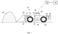
- Fig. 1 shows an example of a work machine 10 comprising a (mobile) carrier 12, one or more booms 14 and a bucket 16 attached in a pivotable or otherwise movable manner to the one or more booms 14.
- the bucket 16 may be coupled to two booms 14.
- the attachment may comprise at least one pivot 22, and the bucket 16 may be turned with respect to the pivot(s).
- the work machine 10 may be an articulated vehicle comprising two sections connected by a joint 32.
- the work machine may be a load and haul (LHD) device, or a device mainly intended for loading.
- LHD load and haul
- the work machine 10 further comprises a first actuator 18 for moving the boom 14 upwards and downwards, and a second actuator 20 for turning the bucket 16 in respect to the pivot 22.
- the actuators 18, 20 may be hydraulically and/or electrically operable actuators, or operable by some other source of energy. It should also be noted that Figure 1 is simplified and e.g. the first actuator 18 and/or the second actuator 20 may in practise comprise more than one actuator. For example, a lever arm arrangement may be applied for connecting a cylinder to the bucket 16.
- the work machine 10 typically comprises a pump system 24 for generating hydraulic pressure for operating various parts of the machine, such as lifting the boom 14, turning the bucket, 16 etc.
- the work machine 10 may comprise one or more other sources of energy, such as an accumulator, a hydrogen container, a fuel tank, etc.
- the work machine 10 may comprise at least one motor 26, such as an electric motor or both an electric and a combustion motor. Power from the motor 26 may be provided by a crank shaft (not shown) to front and/or rear wheels 28 either directly or via a gear box (not shown).
- the work machine 10 comprises at least one control unit 30, which may comprise one or more processors and memory, configured to control at least some functions and/or actuators of the work machine.
- the control unit 30 is configured to control at least operations during bucket loading, and there may be one or more other control units in the work machine for controlling other operations. It is to be appreciated that the control unit 30 may be configured to perform at least some of the below illustrated features, or a plurality of control units or controllers may be applied to perform these features. There may be further operations modules or functions performed by the control unit(s), e.g. an automatic bucket loading function, positioning function, autonomous driving control function, and/or an obstacle detection function.
- the work machine 10 may be an automated work machine, which in its autonomous operating mode may operate/drive independently without requiring continuous user control but which may be taken under external control during states of emergencies, for example.
- the work machine 10 may comprise a wireless data transfer unit 34, by which the control unit 30 may establish a data transmission connection to another (second) control system 40 external to the work machine 10 by utilising a wireless connection provided by a base station or access node 42.
- the data transfer unit 34 may thus be connected to a communications system of the worksite, such as a wireless access system comprising a wireless local area network (WLAN) and/or a cellular communications network (e.g. a 4G, 5G or another generation cellular network).
- WLAN wireless local area network
- cellular communications network e.g. a 4G, 5G or another generation cellular network
- the system 40 may comprise or be connected to a further network(s) and/or data processing system(s), such a worksite management system, a cloud service, a data analytics device/system, an intermediate communications network, such as the internet, etc.
- the system may comprise or be connected to further device(s) or control unit(s), such as a handheld user unit, a vehicle unit, a worksite management device/system, a remote control and/or monitoring device/system, data analytics device/system, sensor system/device, etc.
- a server of the system 40 may be configured to manage at least some operations at the worksite, such as provide a UI for an operator to remotely monitor and, when needed, control automatic operation operations of the work machines and/or assign work tasks for a fleet of vehicles and update and/or monitor task performance and status.
- the work machine 10 may be unmanned, the user interface may be remote from the work machine, and the work machine may be remotely monitored or controlled by an operator in proximity to the work machine (e.g. in the tunnel), or in a control room at the worksite or even long distance away from the worksite via communications network(s).
- the below described features may be applied also in manually-operated machines to assist bucket filling.
- the work machine 10 may comprise a positioning system or unit.
- a positioning system or unit At surface-operated work machines, it may be possible to use satellite-based navigation, such as the GPS system, for determining the location and orientation of the mining vehicle with sufficient accuracy.
- satellite-based navigation such as the GPS system
- positioning based on dead-reckoning and/or scanning tunnel surfaces may be used.
- the work machine 10 may comprise one or more scanning units, or scanners 36, configured to perform scanning of the environment of the work machine.
- the scanner 36 may be a 2D or 3D scanner configured to monitor tunnel walls.
- the control unit 30 may compare operational scanned tunnel profile data to reference profile data stored in an environment model and position the work machine on the basis of finding a match in the environment model to position the work machine and/or correct positioning by dead-reckoning.
- the scanning results are applied to detect position and orientation of the work machine and one or more further elements thereof, such as the scanner 36 or the bucket 16.
- a driving plan, or a route plan may define a route to be driven by the work machine 10 and may be used as an input for automatic control of the work machine.
- the plan may define a start point, an end point, and a set of route points for the automatic drive.
- the driving plan may comprise information of loading area or point and may comprise data for controlling loading of the bucket 16. Bucket loading mode may be initiated in response to the work machine entering a position or route point of loading area in the driving plane.
- the driving plan may be sent via a wired or wireless connection to, or otherwise loaded to the work machine, to a memory of the work machine for access by the control unit 30.
- Bucket loading comprises many stages and actions and it is a difficult task especially for an operator with less experience. If the work machine stops due to too high resistance of the stack of material, the bucket may be lifted upwards, which may enable driving the work machine 10 a bit further, etc.
- the bucket loading procedure by the work machine 10 may be automated, i.e. the machine may autonomously perform a sequence of appropriate movements of the work machine body, the boom 14 and the bucket 16, controlled by the controller unit 30 to fill the bucket 16 and complete the loading by entering a boom position appropriate for leaving the pile 50 and hauling the load to an unloading location.
- the controller unit 30 controls the controller unit 30 to fill the bucket 16 and complete the loading by entering a boom position appropriate for leaving the pile 50 and hauling the load to an unloading location.
- Figure 2 illustrates a method according to some embodiments.
- the method may be performed by a work machine and a controlling apparatus thereof, such as the work machine 10, and by the control unit 30 thereof.
- the method for controlling traction of work machine during loading may comprise detecting 200 a work machine comprising an electric driveline, a boom, and a bucket connected to the boom to enter a bucket loading mode.
- a bucket loading specific traction control procedure is initiated 210 in response to detecting the work machine to enter the bucket loading mode.
- the traction control procedure comprises:
- the bucket loading specific traction control procedure (which may also be referred e.g. as anti-slip control procedure) comprises control action(s) for reducing slipping, configured for and applied during bucket loading. Detecting the wheel slip condition may refer to identifying, based on at least the driveline information, that at least one wheel of the work machine is likely slipping.
- the bucket loading specific traction control parameter set refers to a set of control parameters defined for and applied during bucket loading.
- the parameter set may be defined 240 on the basis of the driveline information, which may be substantially continuously received (thus also after block 230).
- traction control on the basis of the received driveline information, traction control may be repetitively switched on and off (in response to detecting termination of the slip condition).
- level of applied traction control affecting the speed and torque may be adapted based on newly received driveline information. Also further information may be applied in block 230 and/or 240, such as sensor information.
- the driveline information refers generally to information indicative of status or parameter of a driveline (may also be referred to as powerline) component or system.
- Electric driveline components of a work machine typically comprise an inverter unit, an electric motor, a gearbox, and a transmission mechanism.
- the driveline information comprises (only) information indicative of current status of the motor, or a unit controlling the motor.
- the driveline information may be received from a driveline component or a control system or unit thereof.
- the driveline information is received from an inverter unit or another type of (drive control) unit driving or controlling the electric motor.
- the driveline information is generated on the basis of signals from the driveline component(s).
- the driveline information is indicative of driveline rotational speed and/or torque status.
- the slip condition threshold value(s) may comprise driveline threshold value(s), such as threshold value on motor rotational speed or RPM
- the speed controlled in block 250 is to be understood broadly to speed control of the electric driveline, such as instructing the inverter unit with information affecting ground speed or motor speed.
- the work machine may in block 240 select one parameter set amongst the stored parameter sets based at least on the received driveline information.
- the work machine may also be configured to dynamically generate some or all of the values in the parameter set, based on preconfigured control logic.
- the control unit 30 is configured to define new target or limit speed and/or torque value, which is reduced by predetermined amount from current target or limit value, e.g. by 40%.
- Temporal relationship between at least some of the plurality of control parameters in the bucket loading specific traction control parameter set may be defined.
- Such temporal relationship information such as timing information for parameters in the set, may be stored as part of the parameter set.
- the bucket loading specific traction control parameter set may be a sequence of control parameters. Timing of at least some of parameters may be defined in the set.
- a control parameter may define a target value for a controlled entity, and control action may be initiated in block 250 to approach the target value.
- the set of parameters may comprise a plurality of subsequent values for a given parameters. Different values may have different durations, i.e. time periods during which they are applied. There may be another criterion than time elapsed or time threshold for changing the value, some examples being illustrated below.
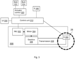
- FIG 3 illustrates an arrangement and elements of the work machine, such as the work machine 10, for controlling the work machine by applying the method of Figure 2 and at least some embodiments thereof.
- driveline 300 of the work machine comprises an electric motor 304 driven by an inverter unit (INU) 302.
- the INU 302 comprises an inverter, which at least in some instances may also be referred to as frequency converter, alternative current (AC) drive, variable speed drive (VSD), or variable frequency drives (VFD), controlling the voltage and frequency of power supplied to an AC motor to control the torque and rotation speed of the motor 304.
- inverter which at least in some instances may also be referred to as frequency converter, alternative current (AC) drive, variable speed drive (VSD), or variable frequency drives (VFD), controlling the voltage and frequency of power supplied to an AC motor to control the torque and rotation speed of the motor 304.
- AC alternative current
- VSD variable speed drive
- VFD variable frequency drives
- Wheels 28, such as front wheels and rear wheels of the work machine 10 are rotated by a transmission mechanism 308.
- the transmission mechanism 308 is rotated by a gear box (or drop) assembly 306.
- the gear box is driven by the electric motor 304.
- the INU 302 is powered by electric energy from an electrical supply of the work machine (not shown).
- the driveline may also comprise or be connected also another type of energy source.
- a combustion motor e.g. a diesel generator is applied, and the generated energy is used directly by the electric driveline or stored in a battery.
- the work machine and the driveline may be hybrid.
- a control system or unit 310 such as the control unit 30, may be configured to perform the method of Figure 2 and receive 220 information from the driveline 300.
- the control unit 310 may comprise one or more computing units/processors executing computer program code stored in memory.
- the control unit may be connected to one or more other control units of a control system of the work machine, in some embodiments by a controller area network (CAN) bus.
- the control unit 310 may thus obtain the driveline information (e.g. provided to the bus by the INU 302) from the bus system.
- CAN controller area network
- the driveline information may indicate current electric motor 304 speed and/or torque.
- further (traction control affecting) information which may assist to identify wheel slipping and/or in block 240, is received 220 from the INU 302.
- Such traction control information may be indicative of one or more of electric motor power, electric motor current, electric motor voltage, electric supply side voltage, electric supply side current, and inverter internal limitation information.
- the control unit 30, 310 determines difference between currently instructed motor speed and current actual motor speed (based on the received driveline information), and applies the difference in block 230 and/or 240 (there may be one or more difference threshold values applied).
- the INU 302 is controlled by the control unit 310 on the basis of parameter(s) in the defined bucket loading specific traction control parameter set to control the driveline 300 of the work machine.
- the control unit 310 may be configured to transmit control signals in accordance with the defined set of control parameters to the INU 302 to control driveline rotational speed and/or torque.
- the bucket loading specific traction control parameter set defined in block 240, and which may be controlled by the control unit 310 as control signals to the driveline 300, may be indicative at least one of electric motor power request and/or limitation, electric motor torque request and/or limitation, speed request and/or limitation, and inverter internal limitation information.
- the control unit 310 may in some embodiments be directly or indirectly connected also to further elements of the driveline, such as the motor 304 or a further controller thereof, or a sensor in the driveline.
- the RPM repetitions per minute
- the control unit 310 may obtain the RPM information from the driveline and process it by an algorithm to detect slippage or spin of the wheels (in case there is a differential lock).
- the algorithm may be configured to maintain the RPM within a predetermined range.
- the driveline RPM can be readily obtained and the wheel RPM calculated therefrom.
- the control unit 310 may be connected to an actuator control unit or (sub)system 320, which may be connected to boom actuator (BoA) 322 and bucket actuator (BuA) 324.
- the control unit 310 may issue control signals during the bucket loading mode, according to defined bucket and/or boom control parameters, which in an embodiment may be adaptively and dynamically defined on the basis of driveline information, to the actuator control system 320, which controls the BoA 322 and BuA 324 to accordingly control the boom 14 and the bucket 16.
- the boom and the bucket may have separate actuator controls, which may be directly connected to the control unit 310.
- Actuator control (sub)system may comprise or be connected to hydraulic circuits having lift and tilt actuator control valves for controlling the rate at which pressurized hydraulic fluid flows to respective lift and tilt hydraulic actuators in proportion to control signals.
- a user interface (UI) 330 may be connected to the control unit 310, comprising e.g. a joystick, a touch screen, or other input means by which an input signal from a user may be provided to the control unit for affecting e.g. the traction control and loading operations.
- UI user interface
- the control unit 310 may be connected to further units in the work machine, such as further sensors or sensor systems 340 and 350.
- sensors include boom or bucket limit sensors, boom or bucket position detection sensors and hydraulic pressure sensors.
- Example sensor 350 may be a wheel rotation sensor.
- the control unit 310 may receive wheel rotation information.
- the control unit may detect 230 the slip condition during the bucket loading mode on the basis of the received wheel rotation information and a predefined wheel rotation or traction control threshold value preconfigured for the bucket loading mode.
- sensor means 350 are arranged at right and left front wheels 28 for determining speed of the front wheels.
- the control unit 310 may determine speed difference of the front wheels based on signals from the sensor means and detect 230 the slip condition in response to the speed difference exceeding a traction control threshold value preconfigured for the bucket loading mode.
- the wheel slip condition is detected 230 and/or traction control parameter set is defined 240 or changed on the basis of information from the sensor means 350, indicative of wheel slip during the bucket loading mode.
- the wheel slip condition may be detected and bucket loading specific traction control performed (and associated parameter set selected) without such sensor information and sensors.
- the wheel rotation sensor and associated information may be used as an additional input to the method.
- block 200 may comprise detecting at least one of:
- the position may refer to a position area, e.g. current position of the boom 14 is in a lower portion of its area of mobility.
- the predefined bucket loading entry position may be a route point associated with loading area, or other type of indicator in position information, such as a loading area indicator.
- the bucket loading mode may be automatically entered in response to detecting that the current position of the work machine 10 matches with the predefined position.
- the associated bucket or boom position may be a predetermined angle or angle area.
- the associated bucket or boom position is detected in response to receiving a signal from a limit switch, whereby position sensor may be avoided. It is to be noted that a combination of conditions may be required; for example, all the first three conditions of the above list need to be met.
- Blocks 220 to 250 may be repeated during the bucket loading mode and the associated traction control procedure.
- the work machine 10, and the control unit 30, 310 thereof (which may also apply to the other embodiments below referring to the work machine), may define, on the basis of the driveline information and one or more threshold conditions, if redefinition or change of applied traction control parameter set or one or more control parameters thereof is to be triggered.
- the bucket loading specific traction control procedure may thus dynamically adapt to the changing conditions detected based on the driveline information.
- the work machine 10 may determine, during the bucket loading mode and the traction control procedure, if a change condition for changing the defined traction control parameter set or at least one parameter in the defined traction control parameter set is met.
- a need to adapt one or more parameters in the defined set is detected, and such parameters may be dynamically adapted during application of the set.
- applied traction control parameter set or at least one parameter in the defined traction control parameter set is (re)defined and changed.
- the change condition may comprise at least one driveline information threshold value, wheel slip condition threshold value, and/or a temporal threshold value, for example.
- Examples of driveline information threshold values which may also be applied as the slip condition threshold value(s) in block 230 and as slip condition termination threshold value(s), include at least one threshold value on driveline or motor rotational speed or RPM, a threshold value on torque and/or power.
- the work machine 10 may thus continue to monitor at least driveline information during and after the controlling 250 on the basis of the defined traction control parameter set.
- one or more further control actions and associated parameters may be defined and applied.
- an updated traction control parameter set may be defined for controlling the speed and torque of the electric driveline to further reduce wheel slipping.
- boom and/or bucket control parameter to (further) reduce the wheel slipping may be defined and applied.
- Time of applying the defined traction control parameter set or some parameters thereof may be monitored. Change of the control parameter set or at least some parameters thereof to control speed and torque of the electric driveline may be controlled in response to the time of applying the defined set exceeding a threshold value. This enables to ensure that a control parameter set (and associated traction control action) is not applied unnecessarily long.
- a parameter in the control parameter set is applied for a predefined period of time identified by the set, i.e. some parameters of the set may be applied only for part of the loading action and application time of the parameter set.
- the system comprising the present bucket loading specific traction control procedure may provide an interface for the user to tune the procedure, e.g. via the UI 330. There may be several parameters affecting sensitivity of the procedure. Even though the present traction control procedure enables to adapt very well to the current slipping conditions based on the driveline information, it may be desirable to be able to control the sensitivity of the procedure, e.g. it may be desirable to allow certain amount of wheel slipping in at least some bucket loading events or stages, or prevent wheel slipping entirely to minimize tear.
- the interface may be configured such that only one (or two/three) sensitivity tuning parameters (or groups of parameters) or profiles are available for control via the UI, enabling simple manual tuning modification by operator during use of the machine.
- the present traction control procedure and parameters thereof may be controlled or configured automatically on the basis of the current location of the work machine. This enables further automatic tuning for varying bucket filling circumstances at different spots of a mine, for example.
- the traction control procedure may be terminated in response to detecting termination of the bucket loading mode.
- the bucket loading mode may be terminated in response to loading completion or finish stage or action being completed or entered (e.g. lifting and shaking boom), the boom entering a driving position, a user input, information indicative of bucket being full enough (e.g. based on hydraulic pressure), the work machine leaving the bucket loading position or area, etc.
- such termination condition is determined in response to receiving a signal from a bucket limit switch.
- the present features and adaptive bucket loading specific traction control procedure facilitate to provide well-functioning traction control for automatized bucket loading, supporting effective bucket filling in varying loading conditions.
- the bucket loading specific traction control is designed and optimized for the very specific bucket loading event, differing substantially from normal driving traction control requirements.
- the present traction control procedure does not have to be configured to support a large number of different normal driving situations, speeds, or conditions. Wheel slipping, and associated wearing of tires, may be reduced, but at the same time appropriate force ensured for bucket filling.
- the driveline information and the electric driveline may be considered as a sensor enabling to substantial improve the optimized operation of traction operations for bucket loading, since the driveline information reflects loading situation very well.
- Based on algorithm suitably configured to apply the driveline information it is possible to have exact knowledge of what is currently happening in the loading process and instantly define and apply appropriate set of control parameters, enabling to have maximum force available against muck pile under current slipping conditions.
- physical sensors such as ground radar, wheel rotation sensor(s) or scanners, are not required for traction control, traction control arrangement may be substantially simplified. Since there are less physical devices susceptible to break or malfunction in the demanding conditions, robustnes is improved. The system has been tested with an LHD and shown to work smoothly and effectively.
- the bucket loading mode may be an automatic bucket loading mode in which control actions and associated control parameters to move the bucket 16, the boom 14, and body of the work machine 10 during the bucket loading mode to carry out bucket loading procedure are performed automatically, controlled by the control unit 30, 310 of the work machine.
- the presently disclosed bucket loading specific traction control procedure may be comprised in or applied for an automatic adaptive bucket loading based on adaptive control parameter set adjustment based on driveline information, enabling to further improve bucket filling efficiency in varying conditions.
- Position of the boom, position of the bucket, and speed of the work machine may be controlled on the basis of a set of control parameters defined based on received driveline information (indicative e.g. of rotational speed and/or torque status).
- Figure 4 illustrates examples and associated information when applying the bucket loading specific traction control procedure, which may be performed by the work machine 30 and the control unit 30, 310.
- the first (from up to down) graph illustrates whether traction control is activated (1.0) or not (0.0).
- Traction control activation may here refer to entering block 240 in response to detecting a wheel slip condition, in the present example on the basis wheel speed difference and/or motor measurements.
- the second graph illustrates left wheel speed (line with dots) and right wheel speed (solid line).
- the third graph illustrates current front wheel speed difference (solid line) and dynamically adapted traction control activation limit for speed difference (line with dots; invariable in this example).
- the fourth graph illustrates motor speed (solid line) and motor speed command (line with dots).
- the fifth graph illustrates motor torque (solid line) and dynamically adapted motor torque limitation (line with dots).
- wheel slip condition is detected based on driveline information.
- Motor speed increases 600 may meet a threshold value in relation to speed command for traction control).
- control algorithm Based on this and other driveline information (such as motor power information, control algorithm detects slip condition and instantly activates 602 traction control.
- This illustrated situation may be a four wheel slip condition.
- Fig. 4 also illustrates how the speed command and torque limit may dynamically adjust during the active traction control to quickly and softly end the slipping.
- the work machine 10 and the control unit thereof 30, 310 may record history information of used traction control parameter sets used during bucket loading modes.
- the traction control parameter set may be defined in block 240 further on the basis of the history information.
- the automatic adaptive loading system may be configured to learn on the basis of the history information and past behavior during the bucket loading.
- the system may be configured to teach the traction control procedure and adapt the parameter sets and/or definition of the parameter sets based on the history information.
- An electronic device comprising electronic circuitries may be an apparatus for realizing at least some embodiments illustrated above, such as the method illustrated in connection with Figure 2 and features illustrated for the control unit 30, 310.
- the apparatus may be comprised in at least one computing device connected to or integrated into a control system of the work machine.
- control system may be an intelligent on-board control system controlling operation of various sub-systems of the work machine, such as a hydraulic system, driveline, a motor, etc, in one example the sub-systems illustrated in Figure 3 .
- Such control systems are often distributed and include many independent modules connected by a bus system of controller area network (CAN) nodes, for example.
- CAN controller area network
- Figure 5 illustrates a simplified example apparatus capable of supporting at least some embodiments of the present invention. Illustrated is a device 500, which may be configured to carry out at least some of the embodiments relating to the bucket loading specific traction related operations illustrated above. In some embodiments, the device 500 comprises or implements the control unit 30, or other module(s), functions and/or unit(s) for performing at least some of the above-illustrated embodiments.
- a processor 510 which may comprise, for example, a single- or multi-core processor.
- the processor 510 may comprise more than one processor.
- the processor may comprise at least one application-specific integrated circuit, ASIC.
- the processor may comprise at least one field-programmable gate array, FPGA.
- the processor may be configured, at least in part by computer instructions, to perform actions.
- the device 500 may comprise memory 520.
- the memory may comprise random-access memory and/or permanent memory.
- the memory may be at least in part accessible to the processor 510.
- the memory may be at least in part comprised in the processor 510.
- the memory may be at least in part external to the device 500 but accessible to the device.
- the memory 520 may be means for storing information, such as parameters 522 affecting operations of the device.
- the parameter information in particular may comprise parameter information affecting the bucket loading specific traction control procedure related features, such as threshold values.
- the memory 520 may be a non-transitory computer readable medium comprising computer program code 524 including computer instructions that the processor 510 is configured to execute.
- computer program code 524 including computer instructions that the processor 510 is configured to execute.
- the processor and/or its at least one processing core may be considered to be configured to perform said certain actions.
- the processor may, together with the memory and computer program code, form means for performing at least some of the above-illustrated method steps in the device.
- the device 500 may comprise a communications unit 530 comprising a transmitter and/or a receiver.
- the transmitter and the receiver may be configured to transmit and receive, respectively, i.a. data and control commands within or outside the work machine.
- the transmitter and/or receiver may be configured to operate in accordance with global system for mobile communication, GSM, wideband code division multiple access, WCDMA, long term evolution, LTE, 3GPP new radio access technology (N-RAT), wireless local area network, WLAN, and/or Ethernet standards, for example.
- the device 500 may comprise a near-field communication, NFC, transceiver.
- the NFC transceiver may support at least one NFC technology, such as NFC, Bluetooth, or similar technologies.
- the device 500 may comprise or be connected to a UI.
- the UI may comprise at least one of a display 540, a speaker, an input device 550 such as a keyboard, a joystick, a touchscreen, and/or a microphone.
- the UI may be configured to display views on the basis of above illustrated embodiments.
- a user may operate the device and control at least some of above illustrated features.
- the user may control the work machine 10 via the UI, for example to manually drive the vehicle, operate a boom, initiate automatic loading, change driving mode, change display views, modify parameters 522, etc.
- the processor 510, the memory 520, the communications unit 530 and the UI may be interconnected by electrical leads internal to the device 500 in a multitude of different ways.
- each of the aforementioned devices may be separately connected to a master bus internal to the device, to allow for the devices to exchange information.
- this is only one example and depending on the embodiment various ways of interconnecting at least two of the aforementioned devices may be selected without departing from the scope of the present invention.
Landscapes
- Engineering & Computer Science (AREA)
- Mining & Mineral Resources (AREA)
- Civil Engineering (AREA)
- General Engineering & Computer Science (AREA)
- Structural Engineering (AREA)
- Geology (AREA)
- Life Sciences & Earth Sciences (AREA)
- Mechanical Engineering (AREA)
- General Life Sciences & Earth Sciences (AREA)
- Geochemistry & Mineralogy (AREA)
- Environmental & Geological Engineering (AREA)
- Fluid Mechanics (AREA)
- Physics & Mathematics (AREA)
- Operation Control Of Excavators (AREA)
- Control Of Vehicle Engines Or Engines For Specific Uses (AREA)
Claims (15)
- Einrichtung, die Mittel umfasst, die dazu ausgelegt sind, die folgenden Schritte durchzuführen:Erfassen (200) einer Arbeitsmaschine (10), die eine elektrische Antriebswelle (300), einen Ausleger (14) und eine Schaufel (16), die mit dem Ausleger verbunden ist, um in einen Schaufelbeladungsmodus einzutreten, umfasst, und Einleiten (210) einer schaufelbeladungsspezifischen Traktionssteuerprozedur in Reaktion auf Erfassen der Arbeitsmaschine, um in den Schaufelbeladungsmodus einzutreten, wobei die Traktionssteuerprozedur die folgenden Schritte umfasst:- Empfangen (220) von Antriebswelleninformationen von zumindest einer Komponente der elektrischen Antriebswelle, wobei die Antriebswelleninformationen Informationen sind, die auf der Basis von Signalen von der zumindest einen Komponente der elektrischen Antriebswelle erzeugt werden, und wobei die zumindest eine Komponente der elektrischen Antriebswelle eine Wechselrichtereinheit, ein Elektromotor, ein Getriebe oder ein Übersetzungsmechanismus ist,- Erfassen (230) einer Radschlupfbedingung während des Schaufelbeladungsmodus ausschließlich auf der Basis der empfangenen Antriebswelleninformationen der zumindest einen Komponente der elektrischen Antriebswelle und zumindest eines Schlupfbedingungsschwellenwerts, der für den Schaufelbeladungsmodus vorab konfiguriert wurde,- Definieren (240) eines schaufelbeladungsspezifischen Traktionssteuerparametersatzes in Reaktion auf die erfasste Schlupfbedingung, und- Steuern (250) von Geschwindigkeit und Drehmoment der elektrischen Antriebswelle auf der Basis des definierten Traktionssteuerparametersatzes,wobei keine physischen Sensoren für die schaufelbeladungsspezifische Traktionssteuerprozedur benötigt werden.
- Einrichtung nach Anspruch 1, wobei die Antriebswelleninformationen zumindest eines von Drehgeschwindigkeit und Drehmomentstatus der elektrischen Antriebswelle angeben.
- Einrichtung nach Anspruch 1 oder 2, wobei die Mittel weiter ausgelegt sind zum- Empfangen von Radrotationsinformationen, und- Erfassen der Schlupfbedingung während des Schaufelbeladungsmodus, zusätzlich zu den Antriebswelleninformationen, weiter auf der Basis der empfangenen Radrotationsinformationen und eines vordefinierten Radrotationsschwellenwerts, derfür den Schaufelbeladungsmodus vorab konfiguriert wurde.
- Einrichtung nach einem vorstehenden Anspruch, wobei das Erfassen (200) der Arbeitsmaschine (10), um in den Schaufelbeladungsmodus einzutreten, Erfassen zumindest eines des Folgenden umfasst:- der Arbeitsmaschine, um in eine vordefinierte Schaufelbeladungseingangsposition einzutreten,- der Schaufel bei einer Position, die mit Beginn der Schaufelbeladung verknüpft ist,- des Auslegers bei einer Position, die mit dem Beginn der Schaufelbeladung verknüpft ist,- einer Eingabe von einem Operator, um Schaufelbeladung einzuleiten,- eines Kurzhebels der Arbeitsmaschine bei einer Position mit dem Beginn der Schaufelbeladung, und- anderer Arbeitsmaschinensteuersystemdaten, die mit Schaufelbeladung verknüpft sind, die Eintreten in den Schaufelbeladungsmodus oder einen Bedarf, in diesen einzutreten, angeben.
- Einrichtung nach einem vorstehenden Anspruch, wobei der schaufelbeladungsspezifische Traktionssteuerparametersatz basierend auf den Antriebswelleninformationen definiert (240) ist, die Informationen von einer Wechselrichtereinheit (302) umfassen und eine oder mehrere von Elektromotorgeschwindigkeits-, Elektromotordrehmoments-, Elektromotorleistungs-, Elektromotorstromstärke-, Elektromotorspannungs-, stromversorgungsseitigen Spannungs-, stromversorgungsseitigen Stromstärke- und wechselrichterinternen Begrenzungsinformationen angeben.
- Einrichtung nach einem vorstehenden Anspruch, wobei der definierte schaufelbeladungsspezifische Traktionssteuerparametersatz eine oder mehrere von Elektromotorleistungsanforderungs-, Elektromotorleistungsbegrenzungs-, Elektromotordrehmomentbegrenzungs-, Elektromotordrehmomentanforderungs-, Geschwindigkeitsanforderungs-, Geschwindigkeitsanforderungs-, Geschwindigkeitsbegrenzungs- und wechselrichterinternen Begrenzungsinformationen angibt.
- Einrichtung nach einem vorstehenden Anspruch, wobei die Einrichtung dazu ausgelegt ist, die Traktionssteuerprozedur in Reaktion auf Erfassen von Beendigung des Schaufelbeladungsmodus zu beenden.
- Einrichtung nach einem vorstehenden Anspruch, wobei die Einrichtung dazu ausgelegt ist, während des Schaufelbeladungsmodus zu ermitteln, ob eine Änderungsbedingung zum Ändern des definierten Traktionssteuerparametersatzes oder zumindest eines Parameters in dem definierten Traktionssteuerparametersatz erfüllt ist, und die Einrichtung dazu ausgelegt ist, den definierten Traktionssteuerparametersatz oder zumindest einen Parameter in dem definierten Traktionssteuerparametersatz in Reaktion darauf, dass die Änderungsbedingung erfüllt ist, zu ändern.
- Einrichtung nach einem vorstehenden Anspruch, wobei die Einrichtung weiter dazu ausgelegt ist, zumindest die Antriebswelleninformationen nach dem Steuern auf der Basis des definierten Traktionssteuerparametersatzes zu überwachen, und wobei in Reaktion auf weiteres Erfassen einer Schlupfbedingung die Einrichtung für Folgendes ausgelegt ist:- Definieren eines aktualisierten Traktionssteuerparametersatzes zum Steuern der Geschwindigkeit und des Drehmoments der elektrischen Antriebswelle, um Radschlupf weiter zu verringern,- Definieren vom Auslegersteuerparameter, um den Radschlupf zu verringern, und/oder- Definieren vom Schaufelsteuerparameter, um den Radschlupf zu verringern.
- Arbeitsmaschine (10), umfassend die Einrichtung nach einem vorstehenden Anspruch.
- Verfahren zum Steuern vom Beladen durch eine Arbeitsmaschine (10), umfassend die folgenden Schritte:Erfassen (200), dass die Arbeitsmaschine (10) eine elektrische Antriebswelle (300), einen Ausleger (14) und eine Schaufel (16), die mit dem Ausleger verbunden ist, um in einen Schaufelbeladungsmodus einzutreten, umfasst, und Einleiten (210) einer schaufelbeladungsspezifischen Traktionssteuerprozedur in Reaktion auf Erfassen, dass die Arbeitsmaschine (10) in den Schaufelbeladungsmodus eintritt, wobei die schaufelbeladungsspezifische Traktionssteuerprozedur die folgenden Schritte umfasst:- Empfangen (220) von Antriebswelleninformationen von zumindest einer Komponente der elektrischen Antriebswelle, wobei die Antriebswelleninformationen Informationen sind, die auf der Basis von Signalen von der zumindest einen Komponente der elektrischen Antriebswelle erzeugt werden, und wobei die zumindest eine Komponente der elektrischen Antriebswelle eine Wechselrichtereinheit, ein Elektromotor, ein Getriebe oder ein Übersetzungsmechanismus ist,- Erfassen (230) einer Radschlupfbedingung während des Schaufelbeladungsmodus ausschließlich auf der Basis der empfangenen Antriebswelleninformationen der zumindest einen Komponente der elektrischen Antriebswelle und zumindest eines Schlupfbedingungsschwellenwerts, der für den Schaufelbeladungsmodus vorab konfiguriert wurde,- Definieren (240) eines schaufelbeladungsspezifischen Traktionssteuerparametersatzes in Reaktion auf die erfasste Schlupfbedingung, und- Steuern (250) von Geschwindigkeit und Drehmoment der elektrischen Antriebswelle auf der Basis des definierten Traktionssteuerparametersatzes,wobei keine physischen Sensoren für die schaufelbeladungsspezifische Traktionssteuerprozedur benötigt werden.
- Verfahren nach Anspruch 11, wobei der schaufelbeladungsspezifische Traktionssteuerparametersatz basierend auf den Antriebswelleninformationen definiert (240) ist, die Informationen von einer Wechselrichtereinheit (302) umfassen und eine oder mehrere von Elektromotorleistungs-, Elektromotorstromstärke-, Elektromotorspannungs-, stromversorgungsseitigen Spannungs-, stromversorgungsseitigen Stromstärke- und wechselrichterinternen Begrenzungsinformationen angeben.
- Verfahren nach Anspruch 11 oder 12, wobei der definierte schaufelbeladungsspezifische Traktionssteuerparametersatz eine oder mehrere von Elektromotorleistungsanforderungs-, Elektromotorleistungsbegrenzungs-, Elektromotordrehmomentbegrenzungs-, Elektromotordrehmomentanforderungs-, Geschwindigkeitsanforderungs-, Geschwindigkeitsanforderungs-, Geschwindigkeitsbegrenzungs- und wechselrichterinternen Begrenzungsinformationen angibt.
- Verfahren nach einem vorstehenden Anspruch 11 bis 13, weiter umfassend: Ermitteln, während des Schaufelbeladungsmodus, ob eine Änderungsbedingung zum Ändern des definierten Traktionssteuerparametersatzes oder zumindest eines Parameters in dem definierten Traktionssteuerparametersatz erfüllt ist, und Ändern des definierten Traktionssteuerparametersatzes oder zumindest eines Parameters in dem definierten Traktionssteuerparametersatz in Reaktion darauf, dass die Änderungsbedingung erfüllt ist.
- Computerprogramm, das Code umfasst, um, wenn er in einer Datenverarbeitungseinrichtung (500) ausgeführt wird, zu veranlassen, dass ein Verfahren in Übereinstimmung mit einem der Ansprüche 11 bis 14 durchgeführt wird.
Priority Applications (5)
| Application Number | Priority Date | Filing Date | Title |
|---|---|---|---|
| EP20173126.2A EP3907332B1 (de) | 2020-05-06 | 2020-05-06 | Antriebsregelung bei ladevorgängen einer bergbaumaschine |
| FIEP20173126.2T FI3907332T3 (fi) | 2020-05-06 | 2020-05-06 | Vedonhallinta kaivostyökoneen kuormaustoimintojen aikana |
| PL20173126.2T PL3907332T3 (pl) | 2020-05-06 | 2020-05-06 | Sterowanie trakcją podczas operacji załadunku maszyny górniczej |
| PCT/EP2021/061959 WO2021224374A1 (en) | 2020-05-06 | 2021-05-06 | Traction control during loading operations of a mining machine |
| ZA2022/10694A ZA202210694B (en) | 2020-05-06 | 2022-09-27 | Traction control during loading operations of a mining machine |
Applications Claiming Priority (1)
| Application Number | Priority Date | Filing Date | Title |
|---|---|---|---|
| EP20173126.2A EP3907332B1 (de) | 2020-05-06 | 2020-05-06 | Antriebsregelung bei ladevorgängen einer bergbaumaschine |
Publications (2)
| Publication Number | Publication Date |
|---|---|
| EP3907332A1 EP3907332A1 (de) | 2021-11-10 |
| EP3907332B1 true EP3907332B1 (de) | 2023-03-01 |
Family
ID=70553976
Family Applications (1)
| Application Number | Title | Priority Date | Filing Date |
|---|---|---|---|
| EP20173126.2A Active EP3907332B1 (de) | 2020-05-06 | 2020-05-06 | Antriebsregelung bei ladevorgängen einer bergbaumaschine |
Country Status (5)
| Country | Link |
|---|---|
| EP (1) | EP3907332B1 (de) |
| FI (1) | FI3907332T3 (de) |
| PL (1) | PL3907332T3 (de) |
| WO (1) | WO2021224374A1 (de) |
| ZA (1) | ZA202210694B (de) |
Families Citing this family (1)
| Publication number | Priority date | Publication date | Assignee | Title |
|---|---|---|---|---|
| JP7808530B2 (ja) * | 2022-09-01 | 2026-01-29 | 日立建機株式会社 | 作業車両 |
Family Cites Families (7)
| Publication number | Priority date | Publication date | Assignee | Title |
|---|---|---|---|---|
| US7337054B2 (en) * | 2004-07-29 | 2008-02-26 | Caterpillar Inc. | Systems and methods for controlling slip |
| US20060207809A1 (en) * | 2005-03-21 | 2006-09-21 | Caterpillar Inc. | Electric drive system having cooling strategy |
| US7853384B2 (en) * | 2007-03-20 | 2010-12-14 | Deere & Company | Method and system for controlling a vehicle for loading or digging material |
| CN102428290B (zh) * | 2009-03-18 | 2013-01-23 | 株式会社小松制作所 | 工程车辆 |
| JP5261419B2 (ja) * | 2010-03-05 | 2013-08-14 | 株式会社小松製作所 | 作業車両及び作業車両の制御方法 |
| RU2658708C1 (ru) | 2014-10-13 | 2018-06-22 | Сандвик Майнинг Энд Констракшн Ой | Устройство для управления рабочей машиной |
| WO2015129932A1 (ja) * | 2015-03-25 | 2015-09-03 | 株式会社小松製作所 | ホイールローダ |
-
2020
- 2020-05-06 EP EP20173126.2A patent/EP3907332B1/de active Active
- 2020-05-06 FI FIEP20173126.2T patent/FI3907332T3/fi active
- 2020-05-06 PL PL20173126.2T patent/PL3907332T3/pl unknown
-
2021
- 2021-05-06 WO PCT/EP2021/061959 patent/WO2021224374A1/en not_active Ceased
-
2022
- 2022-09-27 ZA ZA2022/10694A patent/ZA202210694B/en unknown
Also Published As
| Publication number | Publication date |
|---|---|
| EP3907332A1 (de) | 2021-11-10 |
| FI3907332T3 (fi) | 2023-04-25 |
| PL3907332T3 (pl) | 2023-07-03 |
| ZA202210694B (en) | 2024-11-27 |
| WO2021224374A1 (en) | 2021-11-11 |
Similar Documents
| Publication | Publication Date | Title |
|---|---|---|
| AU2021269094B2 (en) | Autonomous loading operations of a mining machine | |
| EP3961340B1 (de) | Vorrichtung zur steuerung der positionierung eines fahrzeugs an einer untergrundbaustelle | |
| US12332654B2 (en) | Underground worksite vehicle positioning control | |
| EP3907332B1 (de) | Antriebsregelung bei ladevorgängen einer bergbaumaschine | |
| US20240344459A1 (en) | Autonomous mining vehicle control | |
| EP3754450B1 (de) | Autonome fahrzeugüberwachung | |
| EP4261646B1 (de) | Scanner-emulation für ein bergbaufahrzeug | |
| AU2024201114B2 (en) | Mining vehicle calibration | |
| AU2024201115B2 (en) | Mining vehicle calibration | |
| EP4325319B1 (de) | Routenanpassung für bergbaufahrzeug | |
| EP4325318B1 (de) | Hinderniserkennung für bergbaufahrzeug |
Legal Events
| Date | Code | Title | Description |
|---|---|---|---|
| PUAI | Public reference made under article 153(3) epc to a published international application that has entered the european phase |
Free format text: ORIGINAL CODE: 0009012 |
|
| STAA | Information on the status of an ep patent application or granted ep patent |
Free format text: STATUS: THE APPLICATION HAS BEEN PUBLISHED |
|
| AK | Designated contracting states |
Kind code of ref document: A1 Designated state(s): AL AT BE BG CH CY CZ DE DK EE ES FI FR GB GR HR HU IE IS IT LI LT LU LV MC MK MT NL NO PL PT RO RS SE SI SK SM TR |
|
| B565 | Issuance of search results under rule 164(2) epc |
Effective date: 20200921 |
|
| STAA | Information on the status of an ep patent application or granted ep patent |
Free format text: STATUS: REQUEST FOR EXAMINATION WAS MADE |
|
| 17P | Request for examination filed |
Effective date: 20220510 |
|
| RBV | Designated contracting states (corrected) |
Designated state(s): AL AT BE BG CH CY CZ DE DK EE ES FI FR GB GR HR HU IE IS IT LI LT LU LV MC MK MT NL NO PL PT RO RS SE SI SK SM TR |
|
| GRAP | Despatch of communication of intention to grant a patent |
Free format text: ORIGINAL CODE: EPIDOSNIGR1 |
|
| STAA | Information on the status of an ep patent application or granted ep patent |
Free format text: STATUS: GRANT OF PATENT IS INTENDED |
|
| RIC1 | Information provided on ipc code assigned before grant |
Ipc: E21B 43/12 20060101ALI20221027BHEP Ipc: G05B 13/02 20060101ALI20221027BHEP Ipc: E21C 27/30 20060101ALI20221027BHEP Ipc: E02F 9/22 20060101ALI20221027BHEP Ipc: E02F 9/20 20060101ALI20221027BHEP Ipc: E02F 3/43 20060101AFI20221027BHEP |
|
| INTG | Intention to grant announced |
Effective date: 20221130 |
|
| GRAS | Grant fee paid |
Free format text: ORIGINAL CODE: EPIDOSNIGR3 |
|
| GRAA | (expected) grant |
Free format text: ORIGINAL CODE: 0009210 |
|
| STAA | Information on the status of an ep patent application or granted ep patent |
Free format text: STATUS: THE PATENT HAS BEEN GRANTED |
|
| AK | Designated contracting states |
Kind code of ref document: B1 Designated state(s): AL AT BE BG CH CY CZ DE DK EE ES FI FR GB GR HR HU IE IS IT LI LT LU LV MC MK MT NL NO PL PT RO RS SE SI SK SM TR |
|
| REG | Reference to a national code |
Ref country code: GB Ref legal event code: FG4D |
|
| REG | Reference to a national code |
Ref country code: CH Ref legal event code: EP Ref country code: AT Ref legal event code: REF Ref document number: 1551054 Country of ref document: AT Kind code of ref document: T Effective date: 20230315 |
|
| REG | Reference to a national code |
Ref country code: DE Ref legal event code: R096 Ref document number: 602020008392 Country of ref document: DE |
|
| REG | Reference to a national code |
Ref country code: IE Ref legal event code: FG4D |
|
| REG | Reference to a national code |
Ref country code: SE Ref legal event code: TRGR |
|
| REG | Reference to a national code |
Ref country code: LT Ref legal event code: MG9D |
|
| REG | Reference to a national code |
Ref country code: NL Ref legal event code: MP Effective date: 20230301 |
|
| P01 | Opt-out of the competence of the unified patent court (upc) registered |
Effective date: 20230603 |
|
| PG25 | Lapsed in a contracting state [announced via postgrant information from national office to epo] |
Ref country code: RS Free format text: LAPSE BECAUSE OF FAILURE TO SUBMIT A TRANSLATION OF THE DESCRIPTION OR TO PAY THE FEE WITHIN THE PRESCRIBED TIME-LIMIT Effective date: 20230301 Ref country code: NO Free format text: LAPSE BECAUSE OF FAILURE TO SUBMIT A TRANSLATION OF THE DESCRIPTION OR TO PAY THE FEE WITHIN THE PRESCRIBED TIME-LIMIT Effective date: 20230601 Ref country code: LV Free format text: LAPSE BECAUSE OF FAILURE TO SUBMIT A TRANSLATION OF THE DESCRIPTION OR TO PAY THE FEE WITHIN THE PRESCRIBED TIME-LIMIT Effective date: 20230301 Ref country code: LT Free format text: LAPSE BECAUSE OF FAILURE TO SUBMIT A TRANSLATION OF THE DESCRIPTION OR TO PAY THE FEE WITHIN THE PRESCRIBED TIME-LIMIT Effective date: 20230301 Ref country code: HR Free format text: LAPSE BECAUSE OF FAILURE TO SUBMIT A TRANSLATION OF THE DESCRIPTION OR TO PAY THE FEE WITHIN THE PRESCRIBED TIME-LIMIT Effective date: 20230301 Ref country code: ES Free format text: LAPSE BECAUSE OF FAILURE TO SUBMIT A TRANSLATION OF THE DESCRIPTION OR TO PAY THE FEE WITHIN THE PRESCRIBED TIME-LIMIT Effective date: 20230301 |
|
| REG | Reference to a national code |
Ref country code: AT Ref legal event code: MK05 Ref document number: 1551054 Country of ref document: AT Kind code of ref document: T Effective date: 20230301 |
|
| PG25 | Lapsed in a contracting state [announced via postgrant information from national office to epo] |
Ref country code: NL Free format text: LAPSE BECAUSE OF FAILURE TO SUBMIT A TRANSLATION OF THE DESCRIPTION OR TO PAY THE FEE WITHIN THE PRESCRIBED TIME-LIMIT Effective date: 20230301 Ref country code: GR Free format text: LAPSE BECAUSE OF FAILURE TO SUBMIT A TRANSLATION OF THE DESCRIPTION OR TO PAY THE FEE WITHIN THE PRESCRIBED TIME-LIMIT Effective date: 20230602 |
|
| PG25 | Lapsed in a contracting state [announced via postgrant information from national office to epo] |
Ref country code: SM Free format text: LAPSE BECAUSE OF FAILURE TO SUBMIT A TRANSLATION OF THE DESCRIPTION OR TO PAY THE FEE WITHIN THE PRESCRIBED TIME-LIMIT Effective date: 20230301 Ref country code: RO Free format text: LAPSE BECAUSE OF FAILURE TO SUBMIT A TRANSLATION OF THE DESCRIPTION OR TO PAY THE FEE WITHIN THE PRESCRIBED TIME-LIMIT Effective date: 20230301 Ref country code: PT Free format text: LAPSE BECAUSE OF FAILURE TO SUBMIT A TRANSLATION OF THE DESCRIPTION OR TO PAY THE FEE WITHIN THE PRESCRIBED TIME-LIMIT Effective date: 20230703 Ref country code: EE Free format text: LAPSE BECAUSE OF FAILURE TO SUBMIT A TRANSLATION OF THE DESCRIPTION OR TO PAY THE FEE WITHIN THE PRESCRIBED TIME-LIMIT Effective date: 20230301 Ref country code: AT Free format text: LAPSE BECAUSE OF FAILURE TO SUBMIT A TRANSLATION OF THE DESCRIPTION OR TO PAY THE FEE WITHIN THE PRESCRIBED TIME-LIMIT Effective date: 20230301 |
|
| PG25 | Lapsed in a contracting state [announced via postgrant information from national office to epo] |
Ref country code: SK Free format text: LAPSE BECAUSE OF FAILURE TO SUBMIT A TRANSLATION OF THE DESCRIPTION OR TO PAY THE FEE WITHIN THE PRESCRIBED TIME-LIMIT Effective date: 20230301 Ref country code: IS Free format text: LAPSE BECAUSE OF FAILURE TO SUBMIT A TRANSLATION OF THE DESCRIPTION OR TO PAY THE FEE WITHIN THE PRESCRIBED TIME-LIMIT Effective date: 20230701 |
|
| REG | Reference to a national code |
Ref country code: DE Ref legal event code: R097 Ref document number: 602020008392 Country of ref document: DE |
|
| REG | Reference to a national code |
Ref country code: CH Ref legal event code: PL |
|
| PLBE | No opposition filed within time limit |
Free format text: ORIGINAL CODE: 0009261 |
|
| STAA | Information on the status of an ep patent application or granted ep patent |
Free format text: STATUS: NO OPPOSITION FILED WITHIN TIME LIMIT |
|
| PG25 | Lapsed in a contracting state [announced via postgrant information from national office to epo] |
Ref country code: MC Free format text: LAPSE BECAUSE OF FAILURE TO SUBMIT A TRANSLATION OF THE DESCRIPTION OR TO PAY THE FEE WITHIN THE PRESCRIBED TIME-LIMIT Effective date: 20230301 |
|
| REG | Reference to a national code |
Ref country code: BE Ref legal event code: MM Effective date: 20230531 |
|
| PG25 | Lapsed in a contracting state [announced via postgrant information from national office to epo] |
Ref country code: SI Free format text: LAPSE BECAUSE OF FAILURE TO SUBMIT A TRANSLATION OF THE DESCRIPTION OR TO PAY THE FEE WITHIN THE PRESCRIBED TIME-LIMIT Effective date: 20230301 Ref country code: MC Free format text: LAPSE BECAUSE OF FAILURE TO SUBMIT A TRANSLATION OF THE DESCRIPTION OR TO PAY THE FEE WITHIN THE PRESCRIBED TIME-LIMIT Effective date: 20230301 Ref country code: LU Free format text: LAPSE BECAUSE OF NON-PAYMENT OF DUE FEES Effective date: 20230506 Ref country code: LI Free format text: LAPSE BECAUSE OF NON-PAYMENT OF DUE FEES Effective date: 20230531 Ref country code: DK Free format text: LAPSE BECAUSE OF FAILURE TO SUBMIT A TRANSLATION OF THE DESCRIPTION OR TO PAY THE FEE WITHIN THE PRESCRIBED TIME-LIMIT Effective date: 20230301 Ref country code: CH Free format text: LAPSE BECAUSE OF NON-PAYMENT OF DUE FEES Effective date: 20230531 |
|
| 26N | No opposition filed |
Effective date: 20231204 |
|
| REG | Reference to a national code |
Ref country code: IE Ref legal event code: MM4A |
|
| PG25 | Lapsed in a contracting state [announced via postgrant information from national office to epo] |
Ref country code: IE Free format text: LAPSE BECAUSE OF NON-PAYMENT OF DUE FEES Effective date: 20230506 |
|
| PG25 | Lapsed in a contracting state [announced via postgrant information from national office to epo] |
Ref country code: IE Free format text: LAPSE BECAUSE OF NON-PAYMENT OF DUE FEES Effective date: 20230506 |
|
| PG25 | Lapsed in a contracting state [announced via postgrant information from national office to epo] |
Ref country code: IT Free format text: LAPSE BECAUSE OF FAILURE TO SUBMIT A TRANSLATION OF THE DESCRIPTION OR TO PAY THE FEE WITHIN THE PRESCRIBED TIME-LIMIT Effective date: 20230301 Ref country code: BE Free format text: LAPSE BECAUSE OF NON-PAYMENT OF DUE FEES Effective date: 20230531 |
|
| PG25 | Lapsed in a contracting state [announced via postgrant information from national office to epo] |
Ref country code: BG Free format text: LAPSE BECAUSE OF FAILURE TO SUBMIT A TRANSLATION OF THE DESCRIPTION OR TO PAY THE FEE WITHIN THE PRESCRIBED TIME-LIMIT Effective date: 20230301 |
|
| PG25 | Lapsed in a contracting state [announced via postgrant information from national office to epo] |
Ref country code: BG Free format text: LAPSE BECAUSE OF FAILURE TO SUBMIT A TRANSLATION OF THE DESCRIPTION OR TO PAY THE FEE WITHIN THE PRESCRIBED TIME-LIMIT Effective date: 20230301 |
|
| GBPC | Gb: european patent ceased through non-payment of renewal fee |
Effective date: 20240506 |
|
| PG25 | Lapsed in a contracting state [announced via postgrant information from national office to epo] |
Ref country code: GB Free format text: LAPSE BECAUSE OF NON-PAYMENT OF DUE FEES Effective date: 20240506 |
|
| PGFP | Annual fee paid to national office [announced via postgrant information from national office to epo] |
Ref country code: FI Payment date: 20250513 Year of fee payment: 6 |
|
| PGFP | Annual fee paid to national office [announced via postgrant information from national office to epo] |
Ref country code: PL Payment date: 20250414 Year of fee payment: 6 Ref country code: DE Payment date: 20250402 Year of fee payment: 6 |
|
| PGFP | Annual fee paid to national office [announced via postgrant information from national office to epo] |
Ref country code: FR Payment date: 20250422 Year of fee payment: 6 |
|
| PG25 | Lapsed in a contracting state [announced via postgrant information from national office to epo] |
Ref country code: CY Free format text: LAPSE BECAUSE OF FAILURE TO SUBMIT A TRANSLATION OF THE DESCRIPTION OR TO PAY THE FEE WITHIN THE PRESCRIBED TIME-LIMIT; INVALID AB INITIO Effective date: 20200506 |
|
| PGFP | Annual fee paid to national office [announced via postgrant information from national office to epo] |
Ref country code: CZ Payment date: 20250423 Year of fee payment: 6 |
|
| PGFP | Annual fee paid to national office [announced via postgrant information from national office to epo] |
Ref country code: SE Payment date: 20250411 Year of fee payment: 6 |
|
| PG25 | Lapsed in a contracting state [announced via postgrant information from national office to epo] |
Ref country code: HU Free format text: LAPSE BECAUSE OF FAILURE TO SUBMIT A TRANSLATION OF THE DESCRIPTION OR TO PAY THE FEE WITHIN THE PRESCRIBED TIME-LIMIT; INVALID AB INITIO Effective date: 20200506 |
|
| PG25 | Lapsed in a contracting state [announced via postgrant information from national office to epo] |
Ref country code: TR Free format text: LAPSE BECAUSE OF FAILURE TO SUBMIT A TRANSLATION OF THE DESCRIPTION OR TO PAY THE FEE WITHIN THE PRESCRIBED TIME-LIMIT Effective date: 20230301 |