EP3907456A1 - Wärmeabstrahlende phasenwechselvorrichtung - Google Patents
Wärmeabstrahlende phasenwechselvorrichtung Download PDFInfo
- Publication number
- EP3907456A1 EP3907456A1 EP19913546.8A EP19913546A EP3907456A1 EP 3907456 A1 EP3907456 A1 EP 3907456A1 EP 19913546 A EP19913546 A EP 19913546A EP 3907456 A1 EP3907456 A1 EP 3907456A1
- Authority
- EP
- European Patent Office
- Prior art keywords
- phase
- change
- heat
- condensation
- heat dissipation
- Prior art date
- Legal status (The legal status is an assumption and is not a legal conclusion. Google has not performed a legal analysis and makes no representation as to the accuracy of the status listed.)
- Pending
Links
- 230000008859 change Effects 0.000 title description 2
- 230000017525 heat dissipation Effects 0.000 claims abstract description 98
- 238000012546 transfer Methods 0.000 claims abstract description 38
- 238000009833 condensation Methods 0.000 claims description 98
- 230000005494 condensation Effects 0.000 claims description 98
- 238000001704 evaporation Methods 0.000 claims description 28
- 230000008020 evaporation Effects 0.000 claims description 28
- 230000001965 increasing effect Effects 0.000 claims description 11
- 238000010521 absorption reaction Methods 0.000 claims description 9
- 230000004907 flux Effects 0.000 abstract description 14
- 238000001816 cooling Methods 0.000 description 19
- 238000009835 boiling Methods 0.000 description 13
- LFQSCWFLJHTTHZ-UHFFFAOYSA-N Ethanol Chemical compound CCO LFQSCWFLJHTTHZ-UHFFFAOYSA-N 0.000 description 12
- OKKJLVBELUTLKV-UHFFFAOYSA-N Methanol Chemical compound OC OKKJLVBELUTLKV-UHFFFAOYSA-N 0.000 description 12
- 238000010438 heat treatment Methods 0.000 description 10
- 239000007788 liquid Substances 0.000 description 9
- CSCPPACGZOOCGX-UHFFFAOYSA-N Acetone Chemical compound CC(C)=O CSCPPACGZOOCGX-UHFFFAOYSA-N 0.000 description 8
- 230000000694 effects Effects 0.000 description 7
- 238000012360 testing method Methods 0.000 description 6
- XLYOFNOQVPJJNP-UHFFFAOYSA-N water Chemical compound O XLYOFNOQVPJJNP-UHFFFAOYSA-N 0.000 description 6
- RYGMFSIKBFXOCR-UHFFFAOYSA-N Copper Chemical compound [Cu] RYGMFSIKBFXOCR-UHFFFAOYSA-N 0.000 description 5
- 238000005219 brazing Methods 0.000 description 5
- 229910052802 copper Inorganic materials 0.000 description 5
- 239000010949 copper Substances 0.000 description 5
- 238000000034 method Methods 0.000 description 5
- 230000008569 process Effects 0.000 description 5
- PXHVJJICTQNCMI-UHFFFAOYSA-N Nickel Chemical compound [Ni] PXHVJJICTQNCMI-UHFFFAOYSA-N 0.000 description 4
- ATJFFYVFTNAWJD-UHFFFAOYSA-N Tin Chemical compound [Sn] ATJFFYVFTNAWJD-UHFFFAOYSA-N 0.000 description 4
- 238000009792 diffusion process Methods 0.000 description 4
- 238000007747 plating Methods 0.000 description 4
- 238000009834 vaporization Methods 0.000 description 4
- 230000008016 vaporization Effects 0.000 description 4
- 229910000838 Al alloy Inorganic materials 0.000 description 3
- VOPWNXZWBYDODV-UHFFFAOYSA-N Chlorodifluoromethane Chemical compound FC(F)Cl VOPWNXZWBYDODV-UHFFFAOYSA-N 0.000 description 3
- 230000005540 biological transmission Effects 0.000 description 3
- PTVDYARBVCBHSL-UHFFFAOYSA-N copper;hydrate Chemical compound O.[Cu] PTVDYARBVCBHSL-UHFFFAOYSA-N 0.000 description 3
- 239000008367 deionised water Substances 0.000 description 3
- 229910021641 deionized water Inorganic materials 0.000 description 3
- 230000002708 enhancing effect Effects 0.000 description 3
- 238000004519 manufacturing process Methods 0.000 description 3
- 239000000463 material Substances 0.000 description 3
- 238000004381 surface treatment Methods 0.000 description 3
- 238000003466 welding Methods 0.000 description 3
- LVGUZGTVOIAKKC-UHFFFAOYSA-N 1,1,1,2-tetrafluoroethane Chemical compound FCC(F)(F)F LVGUZGTVOIAKKC-UHFFFAOYSA-N 0.000 description 2
- XPDWGBQVDMORPB-UHFFFAOYSA-N Fluoroform Chemical compound FC(F)F XPDWGBQVDMORPB-UHFFFAOYSA-N 0.000 description 2
- XAGFODPZIPBFFR-UHFFFAOYSA-N aluminium Chemical compound [Al] XAGFODPZIPBFFR-UHFFFAOYSA-N 0.000 description 2
- 229910052782 aluminium Inorganic materials 0.000 description 2
- 230000033228 biological regulation Effects 0.000 description 2
- 239000003990 capacitor Substances 0.000 description 2
- 238000006243 chemical reaction Methods 0.000 description 2
- 238000010586 diagram Methods 0.000 description 2
- NNPPMTNAJDCUHE-UHFFFAOYSA-N isobutane Chemical compound CC(C)C NNPPMTNAJDCUHE-UHFFFAOYSA-N 0.000 description 2
- 229910052759 nickel Inorganic materials 0.000 description 2
- GTLACDSXYULKMZ-UHFFFAOYSA-N pentafluoroethane Chemical compound FC(F)C(F)(F)F GTLACDSXYULKMZ-UHFFFAOYSA-N 0.000 description 2
- MSSNHSVIGIHOJA-UHFFFAOYSA-N pentafluoropropane Chemical compound FC(F)CC(F)(F)F MSSNHSVIGIHOJA-UHFFFAOYSA-N 0.000 description 2
- 238000012545 processing Methods 0.000 description 2
- 238000005476 soldering Methods 0.000 description 2
- 238000003860 storage Methods 0.000 description 2
- DDMOUSALMHHKOS-UHFFFAOYSA-N 1,2-dichloro-1,1,2,2-tetrafluoroethane Chemical compound FC(F)(Cl)C(F)(F)Cl DDMOUSALMHHKOS-UHFFFAOYSA-N 0.000 description 1
- 229910000881 Cu alloy Inorganic materials 0.000 description 1
- 229910000861 Mg alloy Inorganic materials 0.000 description 1
- 239000004341 Octafluorocyclobutane Substances 0.000 description 1
- 238000004891 communication Methods 0.000 description 1
- 238000013461 design Methods 0.000 description 1
- 229940087091 dichlorotetrafluoroethane Drugs 0.000 description 1
- RWRIWBAIICGTTQ-UHFFFAOYSA-N difluoromethane Chemical compound FCF RWRIWBAIICGTTQ-UHFFFAOYSA-N 0.000 description 1
- 230000002349 favourable effect Effects 0.000 description 1
- 230000005484 gravity Effects 0.000 description 1
- 239000001282 iso-butane Substances 0.000 description 1
- 238000003754 machining Methods 0.000 description 1
- 238000012986 modification Methods 0.000 description 1
- 230000004048 modification Effects 0.000 description 1
- BCCOBQSFUDVTJQ-UHFFFAOYSA-N octafluorocyclobutane Chemical compound FC1(F)C(F)(F)C(F)(F)C1(F)F BCCOBQSFUDVTJQ-UHFFFAOYSA-N 0.000 description 1
- 235000019407 octafluorocyclobutane Nutrition 0.000 description 1
- 238000005086 pumping Methods 0.000 description 1
- 239000007921 spray Substances 0.000 description 1
- 239000010935 stainless steel Substances 0.000 description 1
- 229910001220 stainless steel Inorganic materials 0.000 description 1
- 239000000126 substance Substances 0.000 description 1
- 239000000758 substrate Substances 0.000 description 1
Images



Classifications
-
- F—MECHANICAL ENGINEERING; LIGHTING; HEATING; WEAPONS; BLASTING
- F28—HEAT EXCHANGE IN GENERAL
- F28D—HEAT-EXCHANGE APPARATUS, NOT PROVIDED FOR IN ANOTHER SUBCLASS, IN WHICH THE HEAT-EXCHANGE MEDIA DO NOT COME INTO DIRECT CONTACT
- F28D15/00—Heat-exchange apparatus with the intermediate heat-transfer medium in closed tubes passing into or through the conduit walls ; Heat-exchange apparatus employing intermediate heat-transfer medium or bodies
- F28D15/02—Heat-exchange apparatus with the intermediate heat-transfer medium in closed tubes passing into or through the conduit walls ; Heat-exchange apparatus employing intermediate heat-transfer medium or bodies in which the medium condenses and evaporates, e.g. heat pipes
-
- F—MECHANICAL ENGINEERING; LIGHTING; HEATING; WEAPONS; BLASTING
- F28—HEAT EXCHANGE IN GENERAL
- F28D—HEAT-EXCHANGE APPARATUS, NOT PROVIDED FOR IN ANOTHER SUBCLASS, IN WHICH THE HEAT-EXCHANGE MEDIA DO NOT COME INTO DIRECT CONTACT
- F28D15/00—Heat-exchange apparatus with the intermediate heat-transfer medium in closed tubes passing into or through the conduit walls ; Heat-exchange apparatus employing intermediate heat-transfer medium or bodies
- F28D15/02—Heat-exchange apparatus with the intermediate heat-transfer medium in closed tubes passing into or through the conduit walls ; Heat-exchange apparatus employing intermediate heat-transfer medium or bodies in which the medium condenses and evaporates, e.g. heat pipes
- F28D15/0266—Heat-exchange apparatus with the intermediate heat-transfer medium in closed tubes passing into or through the conduit walls ; Heat-exchange apparatus employing intermediate heat-transfer medium or bodies in which the medium condenses and evaporates, e.g. heat pipes with separate evaporating and condensing chambers connected by at least one conduit; Loop-type heat pipes; with multiple or common evaporating or condensing chambers
-
- H—ELECTRICITY
- H05—ELECTRIC TECHNIQUES NOT OTHERWISE PROVIDED FOR
- H05K—PRINTED CIRCUITS; CASINGS OR CONSTRUCTIONAL DETAILS OF ELECTRIC APPARATUS; MANUFACTURE OF ASSEMBLAGES OF ELECTRICAL COMPONENTS
- H05K7/00—Constructional details common to different types of electric apparatus
- H05K7/20—Modifications to facilitate cooling, ventilating, or heating
- H05K7/2029—Modifications to facilitate cooling, ventilating, or heating using a liquid coolant with phase change in electronic enclosures
- H05K7/20336—Heat pipes, e.g. wicks or capillary pumps
-
- F—MECHANICAL ENGINEERING; LIGHTING; HEATING; WEAPONS; BLASTING
- F28—HEAT EXCHANGE IN GENERAL
- F28D—HEAT-EXCHANGE APPARATUS, NOT PROVIDED FOR IN ANOTHER SUBCLASS, IN WHICH THE HEAT-EXCHANGE MEDIA DO NOT COME INTO DIRECT CONTACT
- F28D15/00—Heat-exchange apparatus with the intermediate heat-transfer medium in closed tubes passing into or through the conduit walls ; Heat-exchange apparatus employing intermediate heat-transfer medium or bodies
- F28D15/02—Heat-exchange apparatus with the intermediate heat-transfer medium in closed tubes passing into or through the conduit walls ; Heat-exchange apparatus employing intermediate heat-transfer medium or bodies in which the medium condenses and evaporates, e.g. heat pipes
- F28D15/0233—Heat-exchange apparatus with the intermediate heat-transfer medium in closed tubes passing into or through the conduit walls ; Heat-exchange apparatus employing intermediate heat-transfer medium or bodies in which the medium condenses and evaporates, e.g. heat pipes the conduits having a particular shape, e.g. non-circular cross-section, annular
-
- F—MECHANICAL ENGINEERING; LIGHTING; HEATING; WEAPONS; BLASTING
- F28—HEAT EXCHANGE IN GENERAL
- F28D—HEAT-EXCHANGE APPARATUS, NOT PROVIDED FOR IN ANOTHER SUBCLASS, IN WHICH THE HEAT-EXCHANGE MEDIA DO NOT COME INTO DIRECT CONTACT
- F28D15/00—Heat-exchange apparatus with the intermediate heat-transfer medium in closed tubes passing into or through the conduit walls ; Heat-exchange apparatus employing intermediate heat-transfer medium or bodies
- F28D15/02—Heat-exchange apparatus with the intermediate heat-transfer medium in closed tubes passing into or through the conduit walls ; Heat-exchange apparatus employing intermediate heat-transfer medium or bodies in which the medium condenses and evaporates, e.g. heat pipes
- F28D15/025—Heat-exchange apparatus with the intermediate heat-transfer medium in closed tubes passing into or through the conduit walls ; Heat-exchange apparatus employing intermediate heat-transfer medium or bodies in which the medium condenses and evaporates, e.g. heat pipes having non-capillary condensate return means
-
- H—ELECTRICITY
- H05—ELECTRIC TECHNIQUES NOT OTHERWISE PROVIDED FOR
- H05K—PRINTED CIRCUITS; CASINGS OR CONSTRUCTIONAL DETAILS OF ELECTRIC APPARATUS; MANUFACTURE OF ASSEMBLAGES OF ELECTRICAL COMPONENTS
- H05K7/00—Constructional details common to different types of electric apparatus
- H05K7/20—Modifications to facilitate cooling, ventilating, or heating
- H05K7/2029—Modifications to facilitate cooling, ventilating, or heating using a liquid coolant with phase change in electronic enclosures
- H05K7/20309—Evaporators
-
- H—ELECTRICITY
- H05—ELECTRIC TECHNIQUES NOT OTHERWISE PROVIDED FOR
- H05K—PRINTED CIRCUITS; CASINGS OR CONSTRUCTIONAL DETAILS OF ELECTRIC APPARATUS; MANUFACTURE OF ASSEMBLAGES OF ELECTRICAL COMPONENTS
- H05K7/00—Constructional details common to different types of electric apparatus
- H05K7/20—Modifications to facilitate cooling, ventilating, or heating
- H05K7/2029—Modifications to facilitate cooling, ventilating, or heating using a liquid coolant with phase change in electronic enclosures
- H05K7/20318—Condensers
-
- F—MECHANICAL ENGINEERING; LIGHTING; HEATING; WEAPONS; BLASTING
- F28—HEAT EXCHANGE IN GENERAL
- F28D—HEAT-EXCHANGE APPARATUS, NOT PROVIDED FOR IN ANOTHER SUBCLASS, IN WHICH THE HEAT-EXCHANGE MEDIA DO NOT COME INTO DIRECT CONTACT
- F28D21/00—Heat-exchange apparatus not covered by any of the groups F28D1/00 - F28D20/00
- F28D2021/0019—Other heat exchangers for particular applications; Heat exchange systems not otherwise provided for
- F28D2021/0028—Other heat exchangers for particular applications; Heat exchange systems not otherwise provided for for cooling heat generating elements, e.g. for cooling electronic components or electric devices
- F28D2021/0029—Heat sinks
Definitions
- the present invention pertains to the technical field of phase-change heat dissipation devices, and particularly related to a phase-change heat dissipation device for electronic components.
- Phase-change heat dissipation is an efficient heat dissipation mode, the principle thereof is that a phase-change heat exchange medium is used for boiling, gasifying and absorbing heat at a certain temperature, and then the gasified gas is condensed and liquefied at other positions to release heat, so that heat transfer is achieved. Phase-change heat dissipation is widely used because of its good heat transfer effect.
- a phase-change heat dissipation device generally adopts heat pipes for phase-change heat dissipation, and as compared with other traditional heat dissipation modes, the heat pipes for heat dissipation are high in heat transfer efficiency and good in heat dissipation effect.
- a common heat-pipe heat dissipation device is mainly composed of three parts, namely heat pipes, heat radiating fins and a heat conduction base.
- the heat conduction base connects the heating source with the heat dissipation device, the heat source transfers heat to the heat pipes through the heat conduction base, and the heat radiating fins transfer heat of the heat pipes and a phase-change heat exchange medium in the heat pipes to the outside.
- One end (evaporator part) of each of the heat pipes is embedded in or welded on the heat conduction base, and the other end (condenser part) of each of the heat pipes is connected with the heat radiating fins.
- phase-change heat dissipation device in order to realize the evaporation of a phase-change heat exchange medium at a proper temperature, most of the phase-change heat dissipation devices adopt a vacuum pumping mode to reduce the boiling point of the phase-change heat exchange medium.
- a traditional heat pipe adopts deionized water or ethanol as a working medium, which can only be vaporized at a working point by maintaining a certain negative pressure.
- the heat pipe is tubular, the number of heat pipes suitable for being configured for a heat-pipe heat dissipation device is very limited, and the direct contact area between the heat pipes and a heat source is not large, so that, when heat is transferred from the heat source to a phase-change assembly (the heat pipes), great obstacles exist, the heat transfer efficiency is not high, the heat dissipation performance is severely limited, and local high temperature of the base can be caused.
- the heat dissipation mode of the heat pipe is one-dimensional, heat is conducted in a linear mode, the heat dissipation capacity and the heat dissipation effect of the heat pipe are not optimal, the cost for processing the heat-pipe heat dissipation device is high, and for most phase-change heat dissipation devices, most of the heat pipes work in an internal vacuum environment, which limits the flow of the internal phase-change heat exchange medium, and impedes heat dissipation.
- the heat dissipation device before welding, the heat dissipation device must be subjected to surface treatment such as integral nickel plating or copper plating, the processes of welding and surface treatment are of high cost and might pollute the environment; it is difficult for the brazing to ensure that the interface between the heat pipes and the aluminum alloy base is well filled and there is no remaining local gap, and due to the fact that the heat pipes are located below the power device and the heat flux density is large, any gap therein will lead to local temperature rise of the heat source device, resulting in damage to the device.
- the processing cost of the heat-pipe heat dissipation device is high, and it is not friendly to the environment.
- phase-change heat dissipation devices have the problems of large heat transfer thermal resistance, non-uniform heat transfer, high production cost, and low heat exchange efficiency, etc.
- the present invention provides a phase-change heat dissipation device for an electronic device so as to improve the heat transfer efficiency for promotion of fast dissipation of heat.
- phase-change heat dissipation device comprises a phase-change assembly internally provided with a phase-change heat exchange medium, wherein the phase-change heat exchange medium provided in the phase-change assembly is configured such that, in an operating state of the phase-change heat dissipation device, the air pressure in the phase-change assembly is greater than 0.15 MPa.
- phase-change heat exchange medium provided in the phase-change assembly is any one or more of R134a, R142b, R114, R124, R1233Zd(E), R1234Ze(Z), R1234Ze(E), R600a, RC318, RE245cb2, R22, R32, R407C and R410A.
- the phase-change assembly comprises an evaporator part and a condenser part, an evaporation chamber is formed in the evaporator part, a condensation chamber is formed in the condenser part, the evaporation chamber is communicated with the condensation chamber, and the phase-change heat exchange medium in the evaporation chamber is configured to absorb heat from a heating source and transfer the heat to the condensation chamber, and the condensation chamber is configured to radiate heat outwards, so as to cool the heat source.
- the evaporation chamber is a planar or curved chamber.
- the condenser part comprises a plurality of condensation support plates, and the condensation chamber comprises a planar chamber correspondingly arranged inside each of the condensation support plates; or the condenser part comprises a plurality of condensation branch pipes, and the condensation chamber comprises a cylindrical chamber correspondingly arranged inside each of the condensation branch pipes; or the condenser part comprises a plurality of condensation conical pipes, and the condensation chamber comprises a conical chamber correspondingly arranged inside each of the condensation conical pipes.
- the condenser part is connected to the evaporator part directly or through a pipeline.
- the inner wall of the condenser part is provided with a condensation enhancement structure
- the outer wall of the condenser part is provided with fins or ribs for increasing the condensation area
- a plurality of ribs, bumps or fins are arranged inside the evaporator part and condenser part to increase the pressure bearing capability.
- the outer wall of the evaporator part is in contact with the heat source.
- the outer surface of the evaporator part is provided with a contact heat absorption surface
- the heating source is provided with a heat source surface
- the contact heat absorption surface of the evaporator part is in contact with the heat source surface of the heating source
- both the heat source surface and the contact heat absorption surface are planar.
- the manufacturing of the phase-change heat dissipation device of the present invention does not need surface treatment processes such as copper plating and nickel plating, the phase-change structure and the cooling fins of the heat dissipation device are directly welded into a whole by high-temperature brazing, a heating source (such as a power device CPU) makes contact with the phase-change heat dissipation device, then low-temperature tin soldering is applied to avoid gaps, and thus the heat transfer limit of the phase-change heat dissipation device of the present invention is remarkably increased (far greater than 200W).
- a heating source such as a power device CPU
- the present invention can be applied to power electronic components such as chips, resistors, capacitors, inductors, storage media, light sources and battery packs for heat dissipation.
- phase-change heat dissipation device of the present invention is described in further details below in conjunction with the accompanying drawings.
- Boiling heat transfer refers to a heat transfer process wherein heat is transferred to liquid from a wall surface to enable the liquid to be boiled and vaporized.
- Vaporization core is defined as a carrier for starting liquid boiling.
- Thermal conductivity it is defined as that, when two parallel planes with a distance of 1 meter and an area of 1 square meter each are taken perpendicular to the direction of heat conduction inside an object, and if the temperatures of the two planes differ by 1 K, the amount of heat conducted from one plane to the other plane in 1 second is defined as the thermal conductivity of the substance in Watt *m -1 *K -1 (W ⁇ m -1 ⁇ K -1 ).
- Thermal resistance it is defined as the ratio between the temperature difference across an object and the power of a heat source in Kelvin per Watt (K/W) or degrees Celsius per Watt (°C/W) when heat is transferred across the object.
- the heat transfer coefficient which is the amount of heat transferred through a unit area per unit time in watts per square meter per degree (W/m 2 ⁇ K, where K can be replaced by °C) under conditions of stable heat transfer with an air temperature difference of 1 degree (K or °C) between two sides of a building envelope, reflects the intensity of the heat transfer process.
- Q is the amount of heat
- t is the time
- S is the cross-sectional area
- the unit of heat flux density is J/(m 2 ⁇ s).
- Positive pressure when the temperature of the contact part between the heat dissipation device and the heat source is stable, the pressure in the phase-change assembly of the heat dissipation device being more than 1.5 times of the standard atmospheric pressure (more than 0.15 MPa) is defined as positive pressure.
- Micro-positive pressure when the temperature of the contact part between the heat dissipation device and the heat source is stable, the pressure in the phase-change assembly of the heat dissipation device being between 0.1 MPa and 0.15 MPa is defined as micro-positive pressure.
- the air pressure in the phase-change assembly is micro-positive pressure during working.
- Negative pressure when the temperature of the contact part between the heat dissipation device and the heat source is stable, the pressure in the phase-change assembly of the heat dissipation device being smaller than 0.1 MPa is defined as negative pressure.
- the pressure in the phase-change assembly when water is adopted as the phase-change heat exchange medium, the pressure in the phase-change assembly must be negative pressure during working, otherwise, the phase-change heat exchange medium cannot start functioning, and the heat dissipation device fails.
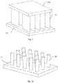
- the phase-change heat dissipation device 10 comprises an evaporator part 11, a condenser part 12 and a phase-change heat exchange medium 20 arranged in the evaporator part 11 or the condenser part 12, and the evaporator part 11 and the condenser part 12 jointly form a three-dimensional heat exchange structure.
- the working pressure in the phase-change heat dissipation device 10 is higher than 0.15 MPa, and the phase-change heat dissipation device 10 is in a positive pressure state.
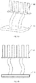
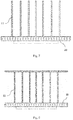
- the evaporator part 11 and the condenser part 12 can be directly connected together (shown in Figs. 1a-4b ), and the evaporator part 11 and the condenser part 12 can also be of a separated structure (shown in Figs. 5a-6b ) connected together through a pipeline.
- the condenser 12 may be placed horizontally or vertically, with the configuration and placement orientation being changed according to the structural design of the system in which the CPU board is placed.
- the heating source 30 is directly installed on the evaporator part 11 of the phase-change assembly, heat is directly transferred to the phase-change heat exchange medium 20 through the thin wall of the evaporator part 11, the phase-change heat exchange medium 20 absorbs heat to generate phase change, so that pressure difference is generated between the evaporator part 11 and the condenser part 12 in the phase-change heat dissipation device 10, and therefore the phase-change heat exchange medium 20 is driven to flow towards the condenser part 12.
- the phase-change medium After the phase-change medium is condensed in the condenser part 12, the phase-change medium returns to the evaporator part 11 by gravity or capillary force, so as to form a circulation.
- the phase-change heat dissipation device 10 comprises a phase-change assembly, the phase-change assembly is of a closed structure with a chamber inside, the phase-change assembly is internally provided with a phase-change heat exchange medium 20, the inner chamber of the phase-change assembly is of a fully-communicated structure, and the phase-change heat exchange medium 20 can circularly flow in the whole inner chamber of the phase-change assembly.
- the phase-change assembly is provided with an evaporator part 11 and a condenser part 12, an evaporation chamber is formed in the evaporator part 11, a condensation chamber is formed in the condenser part 12, the evaporation chamber of the evaporator part 11 is communicated with the condensation chamber of the condenser part 12, the evaporation chamber and the condensation chamber form an inner chamber of the phase-change assembly, and the condenser part 12 is connected with cooling fins.
- the phase-change heat exchange medium 20 in the evaporation chamber absorbs heat from the heat source 30 and then is vaporized and flows into the condensation chamber to be cooled and liquefied, and the condensation chamber radiates heat outwards through the cooling fins. Therefore, the phase-change heat dissipation device 10 can transfer heat of the heat source 30 to air or other gaseous cooling media to achieve the effect of heat dissipation and cooling of the heat source.
- the evaporator part 11 of the phase-change assembly is a planar plate-shaped body or a curved plate-shaped body with a chamber inside, a planar evaporation chamber or a curved-surface-shaped evaporation chamber is formed inside the evaporator part 11, and the planar chamber or the curved-surface-shaped chamber inside the evaporator part 11 is communicated with the condensation chamber inside the condenser part 12.
- the condenser part 12 comprises a plurality of condensation support plates with chambers inside, the interiors of the condensation support plates are planar condensation chambers, the plurality of condensation support plates are connected to the evaporator part 11, and the planar condensation chambers inside the condensation support plates are communicated with the planar evaporation chamber or the curved evaporation chamber inside the evaporator part 11.
- the condensation support plates are preferably arranged in parallel in rows, the condensation support plates are perpendicularly connected to the evaporator part 11, the outer sides of the condensation support plates are connected with cooling fins, and the heat in the condensation support plates is radiated to the outside through the cooling fins.
- the evaporator part 11 is not limited to be of a plate-shaped body structure, and can also be of other cylindrical structures as long as the lower bottom surface thereof is planar.
- a condensation enhancement structure is arranged on the inner wall of the condenser part 12, the condensation enhancement structure can be capillary structures distributed on the inner wall of the condenser part 12, the capillary structures are kidney-shaped columnar or cylindrical or conical structures, and the capillary structures have a capillary effect, so that the vaporized phase-change heat exchange medium 20 can flow along the condensation chamber more quickly and uniformly, and the condensed phase-change heat exchange medium 20 can also be quickly refluxed to the evaporation chamber.
- the heat exchange area of the condensation chamber can be increased by the capillary structures, and the heat transfer speed is increased.
- the condenser part 12 further comprises a condensation top plate 121, a planar condensation chamber or a curved condensation chamber is formed in the condensation top plate 121, the part of condensation chamber in the condensation top plate 121 is communicated with the part of condensation chamber in the condensation support plates, and the whole condenser part 12 is in a comb shape.
- the phase-change heat exchange medium 20 absorbs heat in the evaporation chamber of the evaporator part 11, heat is dissipated through the condensation support plates and the condensation top plate 121 of the condenser part 12, and the phase-change heat exchange medium 20 circularly flows in the evaporation chamber of the evaporator part 11 and the condensation chamber in the condensation support plates and the condensation top plate 121 so as to dissipate heat of the heat source 30.
- the condensation top plate 121 may be integrally formed with the condensation support plates.
- the evaporator part 11 and the condenser part 12 of the phase-change assembly are also preferably integrally formed.
- the condensation support plates in the condenser part 12 take other forms, that is, the condenser part 12 comprises a plurality of cylindrical condensation branch pipes, and the condensation chamber comprises a cylindrical chamber correspondingly arranged inside each of the condensation branch pipes.
- the condenser part 12 can also comprise a plurality of condensation conical pipes, and the condensation chamber comprises a conical chamber correspondingly arranged inside each of the condensation conical pipes.
- the condensation chamber of the condenser part 12 is not directly connected with the evaporator part 11, and the condensation chamber of the condenser part 12 is connected to the evaporator part 11 through a pipeline, so that the condenser part 12 can be reasonably arranged according to the internal structure of the system of the heat source 30.
- the evaporator part 11 and the condenser part 12 of the phase-change assembly are directly communicated, the evaporator part 11 at one end of the phase-change assembly is directly communicated with the condenser part 12 at the other end of the phase-change assembly, and in the evaporation and condensation process of the phase-change heat exchange medium 20 in the phase-change assembly, horizontal and vertical three-dimensional diffusion of heat from one end of the phase-change assembly to the other end of the phase-change assembly can be achieved, and the temperature uniformity of the inner chamber of the whole phase-change assembly, especially of the condensation chamber in the condenser part 12, is improved.
- the evaporator part 11 is in direct contact with the heat source 30, that is, the surface of the evaporator part 11 (the outer surface of the evaporation chamber) is in direct contact with the heat source 30, and the surface of the evaporator part 11 directly replaces a substrate of an existing heat dissipation device, so that the heat transfer efficiency between the heat source 30 and the evaporator part 11 is improved.
- the evaporator part 11 is preferably a planar plate-shaped body with a chamber inside, one side of the evaporator part 11 is provided with a contact heat absorption surface, the heat source 30 is provided with a planar heat source surface, and the contact heat absorption surface of the evaporator part 11 is in contact with the heat source surface of the heat source 30.
- the area of the heat source surface of the heat source 30 is smaller than the area of the contact heat absorption surface of the evaporator part 11 of the phase-change assembly, and the internal phase-change heat exchange medium 20 can rapidly transfer heat from the heat source 30 to the evaporator part 11 of the phase-change assembly in two-dimensional directions through phase-change flow, so that the temperature in the evaporation chamber of the phase-change assembly can be ensured to be uniform.
- the vaporized phase-change heat exchange medium 20 enters the condensation support plates and flows in a third direction which is perpendicular to the evaporator part 11 having a planar plate-shaped body, i.e., perpendicular to the two-dimensional heat dissipation directions inside the evaporator part 11.
- a plurality of ribs, bumps or fins are arranged inside the evaporator part 11 and/or the condenser part 12 so as to improve the pressure bearing capability.
- the phase-change assembly and the cooling fins can be made of copper, aluminum, copper alloy, aluminum alloy, magnesium alloy or stainless steel materials, for example, the phase-change assembly and the cooling fins are made of copper or aluminum materials, and the phase-change assembly and the cooling fins are preferably connected by brazing so as to reduce the contact thermal resistance between the phase-change assembly and the cooling fins. The temperature difference between the cooling fins and the heat source 30 is thereby reduced. After the heat source 30 (such as a power device CPU) and the phase-change heat dissipation device 10 (such as an evaporator part 11 thereof) are in contact connection, low-temperature tin soldering is applied to avoid gaps.
- the heat source 30 such as a power device CPU
- the phase-change heat dissipation device 10 such as an evaporator part 11 thereof
- the cooling fins and the outer walls of the condensation supporting plates are welded together, the pressure bearing capability of the condensation support plates is improved, when the heat dissipation device works, the internal working pressure of the condenser part 12 and the evaporator part 11 can be increased, and if the internal working pressure is increased to be higher than 1MPa, an interwoven structure formed by welding the cooling fins and the condensation support plates can ensure that the condenser part 12 is able to bear the strength required by working.
- the condenser part 12 does not deform, and normal work of the heat dissipation device is guaranteed.
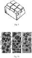
- heat exchange enhancement structures can be protrusions or channels formed on the outer surface of the condenser part 12 or the evaporator part 11 ( FIG. 9 ), or can be porous structures formed on the surface of the condenser part 12 or the evaporator part 11 in a sintered manner ( FIG. 10 ).
- the phase-change heat exchange medium 20 can perform boiling heat exchange more efficiently, heat diffusion is more uniform and rapid, and heat transfer to the external environment is more efficient due to the increase of the heat exchange area, wherein the heat exchange enhancement structure can be selected according to the power density and the machining and manufacturing cost of the heat source 30.
- phase-change heat exchange medium 20 in the phase-change assembly absorbs heat from the heat source 30 and then diffuses along a two-dimensional plane in the inner evaporation chamber of the evaporator part 11, and then the phase-change heat exchange medium 20 vaporizes and flows into the condensation support plates of the condenser part 12 perpendicular to the evaporator part 11.
- phase-change heat exchange medium 20 that has flowed into the condensation support plates then flows into the condensation top plate 121, cooling fins are connected to the outer surfaces of the condensation support plates and the condensation top plate 121, and heat carried by the phase-change heat exchange medium 20 in the condensation support plates and the condensation top plate 121 is radiated outwards through the cooling fins, so that a more favorable heat dissipation effect and performance are obtained.
- the evaporation chamber of the evaporator part is a planar or curved-surface-shaped thin-walled chamber
- a capillary structure for enhancing boiling heat exchange is arranged in the evaporator part
- the condenser part comprises a plurality of hollow condensation support plates or condensation branch pipes or condensation conical pipes, and structures for enhancing condensation heat exchange are arranged in the hollow support plates, hollow cylindrical pipes or hollow conical pipes, fins or ribs capable of increasing the condensation heat exchange area are connected to the exterior of the condenser part, so that the heat exchange performance is good.
- the environment temperature in the heat dissipation device is lower than the boiling point of the phase-change medium, the pressures at various sites of the internal chamber of the phase-change assembly are the same, and the internal pressure can be in a standard atmospheric pressure or negative pressure state.
- the phase-change assembly is in a working state, the environment temperature is higher than the boiling point of the phase-change medium, the temperatures at various sites in the phase-change assembly are different, so that the pressures thereof are different, and the heat exchange in the phase-change assembly is based on the fact that the phase-change heat exchange medium 20 of the evaporator part 11 can be conveyed to the condenser part 12 by pressure difference induced by temperature difference in the phase-change assembly, so that heat exchange is realized.
- the conveying power for the phase-change heat exchange medium 20 from the evaporator part 11 to the condenser part 12 is derived from the pressure difference of the phase-change heat exchange medium 20 at different temperatures.
- the transport capability of the phase-change assembly from the evaporator part 11 to the condenser part 12 is mainly determined by the pressure difference of the phase-change heat exchange medium 20 between the evaporator part 11 and the condenser part 12, the latent heat of vaporization of the phase-change heat exchange medium 20, and the density of the phase-change heat exchange medium 20.
- phase-change heat exchange medium 20 include water, methanol, ethanol, and acetone, and these existing phase-change heat exchange media 20 are in a negative or micro-positive pressure state in operation.
- the working pressure is in a negative pressure or micro-positive pressure state, namely the air pressure is less than 0.15 MPa.
- the heating power of electronic devices is larger and larger, the heating power of a common CPU or GPU is larger than 200 W, and the power density is larger than 60000 J/m 2 ⁇ s.
- the surface temperature of the heat dissipation device is 60 °C, for a ⁇ 6mm*150mm copper-water heat pipe, the maximum transmission capacity of the temperature of the condenser part 12 is only 35W.
- the maximum heat transfer capacity by using the copper-water heat pipes is only about 140W, residual heat needs to be conducted through the bottom of the heat dissipation device, and although ethanol, methanol and acetone adopted as the phase-change heat exchange medium 20 can increase the pressure difference and increase the transmitted volume flow, however, the latent heat of vaporization of deionized water is much higher than those of ethanol, methanol, acetone and the like when the volume flow thereof are equal, and therefore the heat transfer capacity of deionized water is stronger than those of ethanol, methanol, acetone and the like when the heat flux density is low and the temperature difference is the same.
- the heat transfer capacity of the traditional copper-water heat pipes is not enough to meet the requirement of high-power heat dissipation of electronic devices.
- the power of the heat source 30 adopts frequency conversion regulation
- the condenser part 12 adopts liquid cooling
- the amount of liquid is provided by a liquid cooling test device
- the liquid inlet temperature is constant at 35°C
- the temperature of the heat source 30 is guaranteed to be controlled at 40°C
- different phase-change heat exchange media 20 are used, the working pressures and the heating powers inside the phase-change assembly are tested, and the test results are shown in Table 1:
- the test results of heat flux densities of different phase-change heat exchange media 20 are as follows: Table 1 Name of the medium Saturation Temperature (°C) Saturation Pressure (MPa) Boiling Heat Flow Density (W/cm 2 ) Water 40 0.007381 16.5 R142b 40 0.522 26.3 R124 40 0.322 22.3 R1234Ze(E) 40 0.7665 35.8 R134a 40 1.0166 36.5 R1234Ze(Z) 40 0.4918 24.8 R1233Zd(E) 40 0.21548 20.5 R600a 40 0.5312 23.1 RC318 40 0.495 23.1 RE245cb2 40 0.3325 21.6
- R134a is tetrafluoroethane (CF 3 CH 2 F)
- R114 is dichlorotetrafluoroethane (CCIF 2 CCIF 2 )
- R124 is tetrafluoromonochloroethane (CHCIFCF 3 )
- R125 is pentafluoroethane (CHF 2 CF 3 )
- R600a is isobutane (CH(CH 3 ) 3 )
- RC318 is octafluorocyclobutane (cyclo-C 4 F 8 )
- R245fa or R245ca refers to pentafluoropropane (CHF 2 CF 2 CH 2 F)
- R32 is trifluoromethane (CH 2 F 2
- the power of the heat source 30 adopts frequency conversion regulation, the condenser part 12 is air-cooled, the air volume is provided by a test wind tunnel, the inlet air temperature is 25°C, the outlet air temperature is 50°C, the temperature of the heat source 30 is guaranteed to be controlled at 60°C, different phase-change heat exchange media 20 are used, the working pressures and the heating powers inside the phase-change assembly are tested, and the test results are shown in Table 2:
- Table 2 Phase-change medium Heat source temperature (°C) Heat source power (W) Phase-Change Assembly Internal Pressure (MPa) Inlet air Temperature (°C) Outlet air temperature (°C) Air volume (m 3 /h) R142b 60 305.9 0.52 25 50 64.7 R114 60 210 0.33 25 50 44.57 R124 60 297 0.59 25 50 63 R134a 60 333 0.70 25 50 70.7 RE245cb2 60 236 0.33 25 50 50
- the transmission capacity of the phase-change assembly is greatly increased due to the increase of pressure difference in the phase-change assembly by using a phase-change heat exchange medium 20 having a boiling point of less than 30°C at the standard atmospheric pressure, and the transmission capacity is significantly improved (much greater than 200 W) for a CPU of size 45mm*69mm and a heat dissipation device of the same volume by using a phase-change heat exchange medium 20 such as R134a, R142b, R114, R124, R1233Zd(E), R1234Ze(Z), R1234Ze(E), R600a, RC318, RE245cb2.
- phase-change heat exchange medium selected from R134a, R142b, R114, R124, R1233Zd(E), R1234Ze(Z), R1234Ze(E), R600a, RC318, RE245cb2 and the like or a combination thereof, in the phase-change assembly, when the phase-change heat dissipation device is in a working state, the air pressure inside the phase-change assembly can be made higher than 0.15 MPa, and the above phase-change heat exchange medium can be purchased on the market.
- the heat transfer capacity of the phase-change assembly is in positive correlation with the internal air pressure of the phase-change assembly, and the larger the pressure is, the larger the heat exchange power is.
- the present invention can be applied to power electronic devices such as a chip, a resistor, a capacitor, an inductor, a storage medium, a light source and a battery pack for heat dissipation.
Landscapes
- Engineering & Computer Science (AREA)
- Physics & Mathematics (AREA)
- Thermal Sciences (AREA)
- Microelectronics & Electronic Packaging (AREA)
- Life Sciences & Earth Sciences (AREA)
- Sustainable Development (AREA)
- Mechanical Engineering (AREA)
- General Engineering & Computer Science (AREA)
- Cooling Or The Like Of Semiconductors Or Solid State Devices (AREA)
- Cooling Or The Like Of Electrical Apparatus (AREA)
- Memory System Of A Hierarchy Structure (AREA)
Applications Claiming Priority (2)
| Application Number | Priority Date | Filing Date | Title |
|---|---|---|---|
| CN201910086875.0A CN109612314A (zh) | 2019-01-29 | 2019-01-29 | 相变散热装置 |
| PCT/CN2019/125969 WO2020155900A1 (zh) | 2019-01-29 | 2019-12-17 | 相变散热装置 |
Publications (2)
| Publication Number | Publication Date |
|---|---|
| EP3907456A1 true EP3907456A1 (de) | 2021-11-10 |
| EP3907456A4 EP3907456A4 (de) | 2022-02-23 |
Family
ID=66021346
Family Applications (1)
| Application Number | Title | Priority Date | Filing Date |
|---|---|---|---|
| EP19913546.8A Pending EP3907456A4 (de) | 2019-01-29 | 2019-12-17 | Wärmeabstrahlende phasenwechselvorrichtung |
Country Status (6)
| Country | Link |
|---|---|
| US (1) | US20210392783A1 (de) |
| EP (1) | EP3907456A4 (de) |
| JP (1) | JP7603590B2 (de) |
| CN (1) | CN109612314A (de) |
| TW (2) | TWM596328U (de) |
| WO (1) | WO2020155900A1 (de) |
Cited By (1)
| Publication number | Priority date | Publication date | Assignee | Title |
|---|---|---|---|---|
| WO2025138344A1 (zh) * | 2023-12-29 | 2025-07-03 | 尹树彬 | 一种散热板耦合相变传热器件的散热结构 |
Families Citing this family (24)
| Publication number | Priority date | Publication date | Assignee | Title |
|---|---|---|---|---|
| CN109612315A (zh) * | 2019-01-29 | 2019-04-12 | 株洲智热技术有限公司 | 相变散热装置 |
| CN109612314A (zh) * | 2019-01-29 | 2019-04-12 | 株洲智热技术有限公司 | 相变散热装置 |
| CN112020267A (zh) * | 2019-05-30 | 2020-12-01 | 浙江省化工研究院有限公司 | 一种环保型热管工质 |
| CN111010847B (zh) * | 2019-11-22 | 2021-09-07 | 广东工业大学 | 一种均热板式散热装置 |
| KR102869451B1 (ko) * | 2020-01-15 | 2025-10-17 | 주식회사 케이엠더블유 | 전장소자의 방열장치 |
| CN115804252A (zh) * | 2020-03-23 | 2023-03-14 | 株式会社Kmw | 电子元件的散热装置 |
| CN115836587A (zh) * | 2020-08-07 | 2023-03-21 | 华为技术有限公司 | 散热器、散热器制造方法及射频拉远单元 |
| US11778725B2 (en) * | 2021-11-11 | 2023-10-03 | Cisco Technology, Inc. | Thermal interface material (TIM) filling structure for high warpage chips |
| CN114364204B (zh) * | 2021-11-23 | 2023-08-22 | 西安交通大学 | 一种电子设备的相变散热系统 |
| CN114302038B (zh) * | 2021-12-22 | 2024-05-14 | 维沃移动通信有限公司 | 摄像头结构及电子设备 |
| CN114302628A (zh) * | 2022-01-07 | 2022-04-08 | 上海热拓电子科技有限公司 | 一种分离绝缘相变散热器及其散热方法 |
| DE102022100756A1 (de) * | 2022-01-13 | 2023-07-13 | Rittal Gmbh & Co. Kg | Kühlkörper mit Heatpipe für eine elektronische Komponente und eine entsprechende Anordnung |
| CN116483178A (zh) * | 2022-01-17 | 2023-07-25 | 华为云计算技术有限公司 | 一种计算设备及其冷板 |
| CN115084060B (zh) * | 2022-06-10 | 2025-01-14 | 山东大学 | 一种高深宽比微流道热沉及其制备方法与应用 |
| CN116056412A (zh) * | 2022-10-31 | 2023-05-02 | 中国航天三江集团有限公司 | 一种高性能可视化蓄能可调均温板及其使用方法 |
| CN115955820A (zh) * | 2022-12-28 | 2023-04-11 | 北京遥感设备研究所 | 一种相变储热控温板及其制造方法 |
| CN116222282B (zh) * | 2022-12-29 | 2025-11-07 | 北京卫星制造厂有限公司 | 一种具有高效热交换的相变储能超结构及增材工艺方法 |
| CN116182604A (zh) * | 2023-02-20 | 2023-05-30 | 上海威特力热管散热器股份有限公司 | 一种水冷式热管散热器及其制造方法 |
| CN117029134A (zh) * | 2023-08-24 | 2023-11-10 | 吉林大学 | 一种水冷与强化夜间辐射散热耦合的建筑相变材料冷却系统 |
| CN117134539B (zh) * | 2023-09-11 | 2024-03-19 | 贝德凯利电气(苏州)有限公司 | 一种高压直流风机水冷散热结构 |
| CN116923710B (zh) * | 2023-09-18 | 2023-11-17 | 中国航空工业集团公司金城南京机电液压工程研究中心 | 一种飞行器梯级喷雾冷却控制方法及系统 |
| CN119009257B (zh) * | 2024-08-09 | 2025-10-28 | 桂林电子科技大学 | 一种自均温电池包结构体及其适配验证方法 |
| CN118935716B (zh) * | 2024-09-26 | 2025-02-11 | 南京市特种设备安全监督检验研究院 | 一种基于生物基相变的电梯温度调控系统及方法 |
| CN120906280B (zh) * | 2025-10-09 | 2025-12-26 | 宝业集团股份有限公司 | 装配式可翻转储能幕墙系统、制备工艺及翻转控制方法 |
Family Cites Families (30)
| Publication number | Priority date | Publication date | Assignee | Title |
|---|---|---|---|---|
| JPS51127144U (de) * | 1975-04-10 | 1976-10-14 | ||
| JPH10185468A (ja) * | 1996-12-20 | 1998-07-14 | Akutoronikusu Kk | 極大面積比の面間熱拡散接続用プレートヒートパイプ |
| US6237223B1 (en) * | 1999-05-06 | 2001-05-29 | Chip Coolers, Inc. | Method of forming a phase change heat sink |
| US6410982B1 (en) * | 1999-11-12 | 2002-06-25 | Intel Corporation | Heatpipesink having integrated heat pipe and heat sink |
| JP4011272B2 (ja) * | 2000-08-21 | 2007-11-21 | 東芝トランスポートエンジニアリング株式会社 | 半導体冷却装置 |
| CN2720631Y (zh) * | 2003-11-25 | 2005-08-24 | 陈德荣 | 一种翅片热管散热器 |
| CN1564322A (zh) * | 2004-04-07 | 2005-01-12 | 李建民 | 曲面热管散热器及其应用方法 |
| JP2006011638A (ja) * | 2004-06-23 | 2006-01-12 | Shigeru Ito | コンピューター等の電子機器からの放熱機器及びそのシステム |
| US7569170B2 (en) * | 2005-03-04 | 2009-08-04 | E.I. Du Pont De Nemours And Company | Compositions comprising a fluoroolefin |
| CN2874398Y (zh) * | 2005-05-10 | 2007-02-28 | 苏子欣 | 一体化热导管散热结构 |
| TW200706100A (en) * | 2005-07-29 | 2007-02-01 | Hon Hai Prec Ind Co Ltd | Heat sink |
| US7369410B2 (en) * | 2006-05-03 | 2008-05-06 | International Business Machines Corporation | Apparatuses for dissipating heat from semiconductor devices |
| JPWO2011121819A1 (ja) * | 2010-03-29 | 2013-07-04 | 富士通株式会社 | ループ型ヒートパイプ |
| CN202025741U (zh) * | 2011-04-12 | 2011-11-02 | 广州智择电子科技有限公司 | 一种导热装置 |
| DE202011100657U1 (de) * | 2011-05-10 | 2011-07-18 | Asia Vital Components Co., Ltd. | Kondensationsvorrichtung und Kühlmodul mit dieser Kondensationsvorrichtung |
| CN102506600B (zh) * | 2011-09-20 | 2014-01-29 | 华北电力大学 | 冷凝端扩展型一体化平板热管 |
| EP2677261B1 (de) * | 2012-06-20 | 2018-10-10 | ABB Schweiz AG | Zweiphasiges Kühlsystem für elektronische Bauteile |
| CN103759563B (zh) * | 2014-02-21 | 2015-12-09 | 电子科技大学 | 一种利用工质相变循环运动传热的微通道散热装置 |
| JP6237500B2 (ja) * | 2014-07-02 | 2017-11-29 | 三菱マテリアル株式会社 | 多孔質アルミニウム熱交換部材 |
| CN104713395B (zh) * | 2015-02-11 | 2017-01-04 | 上海卫星装备研究所 | 高耐压性平板热管及其加工方法 |
| CN104864755A (zh) * | 2015-05-29 | 2015-08-26 | 厦门大学 | 一种具有翅片-内嵌槽的平板热管吸液芯及其制造方法 |
| US11236948B2 (en) * | 2016-08-24 | 2022-02-01 | Delta Electronics, Inc. | Heat dissipation assembly |
| CN206131833U (zh) * | 2016-11-01 | 2017-04-26 | 东莞市德铫实业有限公司 | 一种新型热管散热器 |
| CN106839840B (zh) * | 2017-01-25 | 2021-07-27 | 中国科学院工程热物理研究所 | 一种基于热压转换效应的传热方法及传热系统 |
| CN207151055U (zh) * | 2017-08-02 | 2018-03-27 | 深圳市迈安热控科技有限公司 | 多孔热管及热管传导散热装置 |
| CN107782189B (zh) * | 2017-09-27 | 2020-03-03 | 北京空间飞行器总体设计部 | 耐正压、大功率平板蒸发器及其加工方法以及基于该蒸发器的平板环路热管 |
| CN109612315A (zh) * | 2019-01-29 | 2019-04-12 | 株洲智热技术有限公司 | 相变散热装置 |
| CN109612314A (zh) * | 2019-01-29 | 2019-04-12 | 株洲智热技术有限公司 | 相变散热装置 |
| CN209745070U (zh) * | 2019-01-29 | 2019-12-06 | 株洲智热技术有限公司 | 相变散热装置 |
| CN209877718U (zh) * | 2019-01-29 | 2019-12-31 | 株洲智热技术有限公司 | 相变散热装置 |
-
2019
- 2019-01-29 CN CN201910086875.0A patent/CN109612314A/zh active Pending
- 2019-12-17 EP EP19913546.8A patent/EP3907456A4/de active Pending
- 2019-12-17 TW TW108216744U patent/TWM596328U/zh unknown
- 2019-12-17 US US17/426,278 patent/US20210392783A1/en not_active Abandoned
- 2019-12-17 TW TW108146139A patent/TWI818134B/zh active
- 2019-12-17 JP JP2021544903A patent/JP7603590B2/ja active Active
- 2019-12-17 WO PCT/CN2019/125969 patent/WO2020155900A1/zh not_active Ceased
Cited By (1)
| Publication number | Priority date | Publication date | Assignee | Title |
|---|---|---|---|---|
| WO2025138344A1 (zh) * | 2023-12-29 | 2025-07-03 | 尹树彬 | 一种散热板耦合相变传热器件的散热结构 |
Also Published As
| Publication number | Publication date |
|---|---|
| JP2022518864A (ja) | 2022-03-16 |
| EP3907456A4 (de) | 2022-02-23 |
| TWM596328U (zh) | 2020-06-01 |
| TWI818134B (zh) | 2023-10-11 |
| CN109612314A (zh) | 2019-04-12 |
| US20210392783A1 (en) | 2021-12-16 |
| WO2020155900A1 (zh) | 2020-08-06 |
| JP7603590B2 (ja) | 2024-12-20 |
| TW202028680A (zh) | 2020-08-01 |
Similar Documents
| Publication | Publication Date | Title |
|---|---|---|
| EP3907456A1 (de) | Wärmeabstrahlende phasenwechselvorrichtung | |
| EP3907455B1 (de) | Wärmeabgebende phasenwechselvorrichtung | |
| US7369410B2 (en) | Apparatuses for dissipating heat from semiconductor devices | |
| JP6403664B2 (ja) | 保護用熱拡散蓋および最適な熱界面抵抗を含む熱電熱交換器部品 | |
| US8773855B2 (en) | Heat-dissipating device and electric apparatus having the same | |
| KR20110026193A (ko) | 발열체 냉각 시스템 및 배터리 냉각 시스템 | |
| KR20060129087A (ko) | 열 파이프 강화 팔레트를 가진 rf 전력 증폭기 어셈블리 | |
| CN209877718U (zh) | 相变散热装置 | |
| CN116499291A (zh) | 散热管、使用散热管传递热量的方法以及用于散热管的热传递流体 | |
| US20190226769A1 (en) | Vapor-liquid phase fluid heat transfer module | |
| US10578368B2 (en) | Two-phase fluid heat transfer structure | |
| CN117950471B (zh) | 一种风冷散热器 | |
| CN209745070U (zh) | 相变散热装置 | |
| CN219018121U (zh) | 一种闪蒸散热系统以及大功率光纤激光设备 | |
| CN104850197A (zh) | 带有复合底板的重力热管式芯片散热器 | |
| CN204576403U (zh) | 重力热管式芯片散热器 | |
| TWI640740B (zh) | Vapor-liquid flow heat transfer module | |
| JP2008244320A (ja) | 冷却装置 | |
| CN219873501U (zh) | 一种散热装置和设备 | |
| CN112739153A (zh) | 一种空间合成功率放大器及其散热装置 | |
| CN100459839C (zh) | 具有多孔结构的支撑柱 | |
| CN213662278U (zh) | 一种空间合成功率放大器及其散热装置 | |
| CN103763888B (zh) | 一种热管散热器及热管散热系统 | |
| CN108282983A (zh) | 两相流热传结构 | |
| TWM557967U (zh) | 汽液相流熱傳模組 |
Legal Events
| Date | Code | Title | Description |
|---|---|---|---|
| STAA | Information on the status of an ep patent application or granted ep patent |
Free format text: STATUS: THE INTERNATIONAL PUBLICATION HAS BEEN MADE |
|
| PUAI | Public reference made under article 153(3) epc to a published international application that has entered the european phase |
Free format text: ORIGINAL CODE: 0009012 |
|
| STAA | Information on the status of an ep patent application or granted ep patent |
Free format text: STATUS: REQUEST FOR EXAMINATION WAS MADE |
|
| 17P | Request for examination filed |
Effective date: 20210802 |
|
| AK | Designated contracting states |
Kind code of ref document: A1 Designated state(s): AL AT BE BG CH CY CZ DE DK EE ES FI FR GB GR HR HU IE IS IT LI LT LU LV MC MK MT NL NO PL PT RO RS SE SI SK SM TR |
|
| A4 | Supplementary search report drawn up and despatched |
Effective date: 20220124 |
|
| RIC1 | Information provided on ipc code assigned before grant |
Ipc: F28D 15/02 20060101AFI20220118BHEP |
|
| DAV | Request for validation of the european patent (deleted) | ||
| DAX | Request for extension of the european patent (deleted) | ||
| STAA | Information on the status of an ep patent application or granted ep patent |
Free format text: STATUS: EXAMINATION IS IN PROGRESS |
|
| 17Q | First examination report despatched |
Effective date: 20240830 |