EP3907461A1 - Modules / éléments intégrés des surfaces de déviation pourvu de cloisons pour l'installation dans des tuyaux/canaux ou dans l'espace enveloppant de l'échangeur de chaleur à faisceau de tubes - Google Patents
Modules / éléments intégrés des surfaces de déviation pourvu de cloisons pour l'installation dans des tuyaux/canaux ou dans l'espace enveloppant de l'échangeur de chaleur à faisceau de tubes Download PDFInfo
- Publication number
- EP3907461A1 EP3907461A1 EP21020233.9A EP21020233A EP3907461A1 EP 3907461 A1 EP3907461 A1 EP 3907461A1 EP 21020233 A EP21020233 A EP 21020233A EP 3907461 A1 EP3907461 A1 EP 3907461A1
- Authority
- EP
- European Patent Office
- Prior art keywords
- built
- tube bundle
- heat exchanger
- bundle heat
- static mixer
- Prior art date
- Legal status (The legal status is an assumption and is not a legal conclusion. Google has not performed a legal analysis and makes no representation as to the accuracy of the status listed.)
- Withdrawn
Links
- 238000009434 installation Methods 0.000 title claims abstract description 16
- 230000003068 static effect Effects 0.000 claims abstract description 29
- 230000000712 assembly Effects 0.000 claims abstract description 9
- 238000000429 assembly Methods 0.000 claims abstract description 9
- 238000002156 mixing Methods 0.000 claims description 13
- 238000000034 method Methods 0.000 claims description 6
- 230000008569 process Effects 0.000 claims description 6
- 230000002787 reinforcement Effects 0.000 claims description 6
- 238000001746 injection moulding Methods 0.000 claims description 4
- 239000004033 plastic Substances 0.000 claims description 3
- 239000000654 additive Substances 0.000 claims description 2
- 230000000996 additive effect Effects 0.000 claims description 2
- 238000005495 investment casting Methods 0.000 claims description 2
- 230000015572 biosynthetic process Effects 0.000 description 4
- 239000000203 mixture Substances 0.000 description 4
- 230000009467 reduction Effects 0.000 description 4
- 238000013517 stratification Methods 0.000 description 4
- 238000012546 transfer Methods 0.000 description 4
- 230000000694 effects Effects 0.000 description 3
- 238000000265 homogenisation Methods 0.000 description 3
- 238000013461 design Methods 0.000 description 2
- 238000002474 experimental method Methods 0.000 description 2
- 230000002349 favourable effect Effects 0.000 description 2
- 229920001225 polyester resin Polymers 0.000 description 2
- 239000004645 polyester resin Substances 0.000 description 2
- 238000010146 3D printing Methods 0.000 description 1
- 239000000853 adhesive Substances 0.000 description 1
- 238000004026 adhesive bonding Methods 0.000 description 1
- 230000001070 adhesive effect Effects 0.000 description 1
- 230000002411 adverse Effects 0.000 description 1
- 238000013459 approach Methods 0.000 description 1
- 230000004323 axial length Effects 0.000 description 1
- 230000008901 benefit Effects 0.000 description 1
- 238000009826 distribution Methods 0.000 description 1
- 230000006872 improvement Effects 0.000 description 1
- 238000005192 partition Methods 0.000 description 1
- 229920005989 resin Polymers 0.000 description 1
- 239000011347 resin Substances 0.000 description 1
- 238000004904 shortening Methods 0.000 description 1
- 238000005476 soldering Methods 0.000 description 1
- 230000008719 thickening Effects 0.000 description 1
- 238000003466 welding Methods 0.000 description 1
Images


Classifications
-
- F—MECHANICAL ENGINEERING; LIGHTING; HEATING; WEAPONS; BLASTING
- F28—HEAT EXCHANGE IN GENERAL
- F28F—DETAILS OF HEAT-EXCHANGE AND HEAT-TRANSFER APPARATUS, OF GENERAL APPLICATION
- F28F9/00—Casings; Header boxes; Auxiliary supports for elements; Auxiliary members within casings
- F28F9/005—Other auxiliary members within casings, e.g. internal filling means or sealing means
-
- B—PERFORMING OPERATIONS; TRANSPORTING
- B01—PHYSICAL OR CHEMICAL PROCESSES OR APPARATUS IN GENERAL
- B01F—MIXING, e.g. DISSOLVING, EMULSIFYING OR DISPERSING
- B01F25/00—Flow mixers; Mixers for falling materials, e.g. solid particles
- B01F25/40—Static mixers
- B01F25/42—Static mixers in which the mixing is affected by moving the components jointly in changing directions, e.g. in tubes provided with baffles or obstructions
- B01F25/421—Static mixers in which the mixing is affected by moving the components jointly in changing directions, e.g. in tubes provided with baffles or obstructions by moving the components in a convoluted or labyrinthine path
- B01F25/422—Static mixers in which the mixing is affected by moving the components jointly in changing directions, e.g. in tubes provided with baffles or obstructions by moving the components in a convoluted or labyrinthine path between stacked plates, e.g. grooved or perforated plates
-
- B—PERFORMING OPERATIONS; TRANSPORTING
- B01—PHYSICAL OR CHEMICAL PROCESSES OR APPARATUS IN GENERAL
- B01F—MIXING, e.g. DISSOLVING, EMULSIFYING OR DISPERSING
- B01F25/00—Flow mixers; Mixers for falling materials, e.g. solid particles
- B01F25/40—Static mixers
- B01F25/42—Static mixers in which the mixing is affected by moving the components jointly in changing directions, e.g. in tubes provided with baffles or obstructions
- B01F25/43—Mixing tubes, e.g. wherein the material is moved in a radial or partly reversed direction
- B01F25/432—Mixing tubes, e.g. wherein the material is moved in a radial or partly reversed direction with means for dividing the material flow into separate sub-flows and for repositioning and recombining these sub-flows; Cross-mixing, e.g. conducting the outer layer of the material nearer to the axis of the tube or vice-versa
- B01F25/4321—Mixing tubes, e.g. wherein the material is moved in a radial or partly reversed direction with means for dividing the material flow into separate sub-flows and for repositioning and recombining these sub-flows; Cross-mixing, e.g. conducting the outer layer of the material nearer to the axis of the tube or vice-versa the subflows consisting of at least two flat layers which are recombined, e.g. using means having restriction or expansion zones
-
- F—MECHANICAL ENGINEERING; LIGHTING; HEATING; WEAPONS; BLASTING
- F28—HEAT EXCHANGE IN GENERAL
- F28D—HEAT-EXCHANGE APPARATUS, NOT PROVIDED FOR IN ANOTHER SUBCLASS, IN WHICH THE HEAT-EXCHANGE MEDIA DO NOT COME INTO DIRECT CONTACT
- F28D7/00—Heat-exchange apparatus having stationary tubular conduit assemblies for both heat-exchange media, the media being in contact with different sides of a conduit wall
- F28D7/16—Heat-exchange apparatus having stationary tubular conduit assemblies for both heat-exchange media, the media being in contact with different sides of a conduit wall the conduits being arranged in parallel spaced relation
- F28D7/1607—Heat-exchange apparatus having stationary tubular conduit assemblies for both heat-exchange media, the media being in contact with different sides of a conduit wall the conduits being arranged in parallel spaced relation with particular pattern of flow of the heat exchange media, e.g. change of flow direction
-
- F—MECHANICAL ENGINEERING; LIGHTING; HEATING; WEAPONS; BLASTING
- F28—HEAT EXCHANGE IN GENERAL
- F28F—DETAILS OF HEAT-EXCHANGE AND HEAT-TRANSFER APPARATUS, OF GENERAL APPLICATION
- F28F9/00—Casings; Header boxes; Auxiliary supports for elements; Auxiliary members within casings
- F28F9/22—Arrangements for directing heat-exchange media into successive compartments, e.g. arrangements of guide plates
-
- F—MECHANICAL ENGINEERING; LIGHTING; HEATING; WEAPONS; BLASTING
- F28—HEAT EXCHANGE IN GENERAL
- F28D—HEAT-EXCHANGE APPARATUS, NOT PROVIDED FOR IN ANOTHER SUBCLASS, IN WHICH THE HEAT-EXCHANGE MEDIA DO NOT COME INTO DIRECT CONTACT
- F28D21/00—Heat-exchange apparatus not covered by any of the groups F28D1/00 - F28D20/00
- F28D2021/0019—Other heat exchangers for particular applications; Heat exchange systems not otherwise provided for
- F28D2021/0098—Other heat exchangers for particular applications; Heat exchange systems not otherwise provided for for viscous or semi-liquid materials, e.g. for processing sludge
-
- F—MECHANICAL ENGINEERING; LIGHTING; HEATING; WEAPONS; BLASTING
- F28—HEAT EXCHANGE IN GENERAL
- F28F—DETAILS OF HEAT-EXCHANGE AND HEAT-TRANSFER APPARATUS, OF GENERAL APPLICATION
- F28F9/00—Casings; Header boxes; Auxiliary supports for elements; Auxiliary members within casings
- F28F9/22—Arrangements for directing heat-exchange media into successive compartments, e.g. arrangements of guide plates
- F28F2009/222—Particular guide plates, baffles or deflectors, e.g. having particular orientation relative to an elongated casing or conduit
- F28F2009/224—Longitudinal partitions
-
- F—MECHANICAL ENGINEERING; LIGHTING; HEATING; WEAPONS; BLASTING
- F28—HEAT EXCHANGE IN GENERAL
- F28F—DETAILS OF HEAT-EXCHANGE AND HEAT-TRANSFER APPARATUS, OF GENERAL APPLICATION
- F28F9/00—Casings; Header boxes; Auxiliary supports for elements; Auxiliary members within casings
- F28F9/22—Arrangements for directing heat-exchange media into successive compartments, e.g. arrangements of guide plates
- F28F2009/222—Particular guide plates, baffles or deflectors, e.g. having particular orientation relative to an elongated casing or conduit
- F28F2009/226—Transversal partitions
Definitions
- the invention relates to assemblies that can be designed in particular as built-in elements, with separators for installation in pipes or ducts as static mixers and / or as baffles with separators for installation in the shell of tube bundle heat exchangers, preferably in the laminar flow area with highly viscous media .
- the invention also relates to static mixers and tube bundle heat exchangers with assemblies of this type.
- Fig. 1 shows a longitudinal section and two cross sections of previously known built-in elements made of deflection surfaces with the partitions as a static mixer installed in a housing (1).
- the built-in elements each consist of a deflection surface and at least 1 separator each on the inlet (I) and outlet side (II) of the deflection surface, viewed in the direction of flow.
- the webs on the input side and on the output side of the deflection surface are preferably at an angle of 90 ° or almost 90 ° to one another.
- a static mixer consists of at least 1 built-in element type A and one built-in element type B following in the direction of flow, whereby the window and closed sub-areas of the deflection surfaces of the following type A and type B elements in the direction of flow alternate or cover each other.
- the axial length of the separating webs is preferably 0.25 to 0.5D.
- the dividers on the entry side can also be shorter or longer than those on the exit side. Deflection surfaces and associated dividers of a built-in element or an assembly can be connected to one another by welding, soldering, gluing, etc., or manufactured individually or as an assembly of several built-in elements as a monolithic component from plastic injection molding, precision casting or additively as a 3D printing.
- EP 3 338 882 A1 an embodiment variant of the deflection surfaces is disclosed in which the windows are significantly smaller than the maximum opening that would be limited by the separating webs and have any shape or are preferably bores. These narrow windows are intended to generate high shear forces for better mixing with different component viscosities.
- the object of the invention is to substantially improve the uniform formation of the layers in such static mixers and to approach the ideal case and to increase the shear forces and the elongation without significantly increasing the pressure loss or creating dead zones.
- such built-in elements should also be able to be installed in the shell space of tube bundle heat exchangers for cross-mixing and improving the heat transfer.
- the object according to the invention can be achieved by making the windows smaller than the maximum size of the known basic structures in the manner according to the invention.
- This is achieved in that the deflection surfaces are extended beyond the separating webs on the inlet side (I) in the direction of the separating webs on the outlet side by the length b in such a way that the transverse propagation of the flow on the outlet side (II) of the deflecting surfaces is exclusively in the direction of the webs are on the exit side and the window areas are reduced in size compared to the maximum partial areas delimited by the separating webs.
- the expansion of the flow on the outlet side is increased and it takes place exclusively in the direction given by the webs.
- the flow and the layers are pulled apart to the maximum and the layer thickness becomes more uniform and therefore less than with the known basic structures.
- the better mixing effect and the higher flow speeds also improve the heat transfer.
- the dividers extend from wall to wall in the built-in elements according to the invention as well as in the known basic structures and thus subdivide the entire cross section into delimited areas with opposite cross-flow directions to the respective windows and on opposite sides of the dividers on the exit side.
- wall to wall means in particular that at least one separating web of the assembly runs between opposing wall areas.
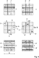
- Fig. 2 shows the extension of the deflecting surfaces according to the invention using the example of 2 windows and 1 separating web each on the entry and exit side using cross-sectional images for a square cross-section.
- Fig. 2 above shows a cross-section in the inlet space (I) with the associated cross-flow direction along the separating web 5 on the inlet side, a cross-section when passing through the deflection surface in the windows 3, 4 in the middle or in the window plane and a cross-section in the outlet space (II) with the direction of expansion along the separating web 6 on the exit side with 2 windows and 1 separating web each on the entry and exit side for a built-in element type A (left half of the picture) in a built-in element according to the invention.
- the sequence of stratification and expansion is indicated schematically when 2 components (gray / white) in a ratio of 1: 1 are added at the inlet of such a static mixer.
- the color gray is shown horizontally striped in the pictures.
- the further layering process in the following type B built-in element with staggered windows is shown in the same way.
- four layers are created in the first element type A from 2 and then in the following insert element from 4 eight layers of the same thickness, etc. This arrangement is relatively insensitive to the position of the stratification at the entry of the first insert element. If the position is incorrect, parallel to the separator at the entrance, only this built-in element is lost for the layering.
- the layering direction is rotated by 90 ° in the first built-in element and the process then continues as normal.
- the open window surface is reduced, the flow is more compressed and the shear is increased.
- the layer thicknesses are much more even because the subsequent expansion is intensified on the exit side.
- the expansion, starting from the narrowest window cross-section, only takes place in the direction specified by the dividers at the exit and not across it.
- the extension is preferably chosen so that the free window area is roughly halved.
- the length b can also be variable over the channel width and the boundary edge can be inclined or in a curved line, cf. Fig. 8 .
- Fig. 3 shows the same representations as for Fig. 2 an embodiment according to the invention for the case that there are 3 windows 3, 4, 5 and only 1 separating web 6 on the entry side but 2 separating webs 7, 8 on the exit side.
- the extension (b) according to the invention of the closed deflecting surface also takes place in all windows and exclusively in the direction of the separating webs on the exit side.
- the process of the model-based layering is shown in the first built-in element type A (left half of the picture) and in the following built-in element type B (right half of the picture) with staggered windows.
- Fig. 4 again shows the same representation as in Fig. 2 or Fig. 3 with 3 windows 3, 4, 5 and 2 separators each (on the entry 6, 7 and exit side 8, 9) for a built-in element type A and on the right for the following built-in element type B according to the embodiment according to the invention.
- the size of the window is shown halved compared to the basic structure.
- the extension is evenly divided by the amount (b / 2) according to the direction of propagation on both sides on the exit side.
- the sequence of stratification and expansion is indicated schematically when 2 components are applied in a ratio of 1: 1 at the inlet. It is also a special feature of this arrangement that the direction of the layering in the first built-in element must be rotated 90 ° to the separating webs at the entrance. If the dosage is incorrect, the same layers are only permanently recombined and consequently there is no mixing!
- Fig. 5 shows the result for a mixer (SQ) according to the invention with a halved window area compared to the mixer according to the prior art EP 0749776 (2L).
- Lo is the layer thickness at the mixer inlet.
- I is the layer thickness at the mixer inlet.
- the built-in elements are connected to one another by axial supports or side walls, or the built-in elements are built into a load-bearing ring or form a monolithic part with this ring if the requirements for compressive strength are particularly high.
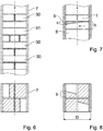
- a particularly favorable design for assemblies as complete mixer rods made of built-in elements according to the invention is shown in FIG Fig. 6 shown.
- the reinforcements (side walls) 7 extend at the edge over several built-in elements or an entire mixer rod.
- These reinforcements are arranged in such a way that the mixer rod can still be manufactured using a simple open / close tool, for example from plastic injection molding.
- these reinforcements are advantageously designed with the cross-section of circular segments. A mixer with an almost rectangular cross-section is then created. Square or slightly rectangular cross-sections result in more uniform layers than round cross-sections.
- Fig. 6 shown as an example.
- a mixer rod with built-in elements Fig. 2 with 2 windows and 2 separators 30 is at least one Built-in element according to Fig. 3 with 3 windows and 3 separators 31 installed. This breaks preferential paths.
- the built-in element 31 there is also a rotation of the direction of the layering and a reversal from the inside to the outside.
- the deflecting surfaces in particular in the outlet space (II), can each be thickened in a wedge-shaped manner towards the wall in the direction of the propagation of the flow Fig. 7 shows (8).
- the corners can be filled and rounded. This is easily possible with components made of injection molding or using an additive process.
- Fig. 8 shows a cross-section through a built-in element according to the invention with deflection surfaces with 2 windows in which the expansion of the covered surfaces over the channel width is different and the edge of the window runs obliquely.
- Fig. 9 shows a design with 12 tubes with deflection surfaces with 2 windows and 1 separator each on the inlet and outlet side.
- D M is the inner diameter of the shell, not shown, of the tube bundle heat exchanger.
- Fig. 10 shows an embodiment with 3 windows and 1 separator on the inlet side and 2 separators on the outlet side in a tube bundle with 24 tubes.
- the windows and closed surfaces in successive built-in elements are each arranged alternately so that no direct, axial passage is possible.
- a square tube division of the tube bundle heat exchanger is advantageous for the simplest possible installation of the separators.
- Fig. 11 shows a perspective view of a tube bundle without a jacket tube with deflection surfaces according to FIG Fig. 9 .
Landscapes
- Engineering & Computer Science (AREA)
- Physics & Mathematics (AREA)
- Thermal Sciences (AREA)
- Mechanical Engineering (AREA)
- General Engineering & Computer Science (AREA)
- Chemical & Material Sciences (AREA)
- Dispersion Chemistry (AREA)
- Chemical Kinetics & Catalysis (AREA)
Applications Claiming Priority (1)
| Application Number | Priority Date | Filing Date | Title |
|---|---|---|---|
| CH00544/20A CH717390A2 (de) | 2020-05-06 | 2020-05-06 | Baugruppen/Einbauelemente aus Umlenkflächen mit Trennstegen für den Einbau in Rohre/Kanäle oder in den Mantelraum von Rohrbündel-Wärmetauschern. |
Publications (1)
| Publication Number | Publication Date |
|---|---|
| EP3907461A1 true EP3907461A1 (fr) | 2021-11-10 |
Family
ID=75690073
Family Applications (1)
| Application Number | Title | Priority Date | Filing Date |
|---|---|---|---|
| EP21020233.9A Withdrawn EP3907461A1 (fr) | 2020-05-06 | 2021-04-23 | Modules / éléments intégrés des surfaces de déviation pourvu de cloisons pour l'installation dans des tuyaux/canaux ou dans l'espace enveloppant de l'échangeur de chaleur à faisceau de tubes |
Country Status (2)
| Country | Link |
|---|---|
| EP (1) | EP3907461A1 (fr) |
| CH (1) | CH717390A2 (fr) |
Cited By (1)
| Publication number | Priority date | Publication date | Assignee | Title |
|---|---|---|---|---|
| WO2024221118A1 (fr) | 2023-04-24 | 2024-10-31 | Felix Streiff | Éléments de mélange statiques comprenant un séparateur ainsi que des surfaces de déviation et mélangeurs statiques |
Citations (6)
| Publication number | Priority date | Publication date | Assignee | Title |
|---|---|---|---|---|
| EP0749776A1 (fr) | 1995-06-21 | 1996-12-27 | Sulzer Chemtech AG | Mélangeur avec corps en forme de tube |
| EP0815929A1 (fr) | 1996-07-05 | 1998-01-07 | Sulzer Chemtech AG | Mélangeur statique |
| EP1426099A1 (fr) | 2002-12-06 | 2004-06-09 | Mixpac Systems AG | Mélangeur statique |
| WO2017027275A2 (fr) * | 2015-08-07 | 2017-02-16 | Nordson Corporation | Éléments de mélange d'entrée ainsi que mélangeurs statiques et procédés de mélange associés |
| EP3338882A1 (fr) | 2016-12-14 | 2018-06-27 | Felix Streiff | Élément mélangeur à résistance et à action de mélange élevés |
| WO2020239734A1 (fr) * | 2019-05-28 | 2020-12-03 | Stamixco Ag | Échangeur de chaleur à faisceau tubulaire comportant des modules/éléments intégrés constitués de surfaces déflectrices et de barrettes de guidage |
-
2020
- 2020-05-06 CH CH00544/20A patent/CH717390A2/de not_active Application Discontinuation
-
2021
- 2021-04-23 EP EP21020233.9A patent/EP3907461A1/fr not_active Withdrawn
Patent Citations (6)
| Publication number | Priority date | Publication date | Assignee | Title |
|---|---|---|---|---|
| EP0749776A1 (fr) | 1995-06-21 | 1996-12-27 | Sulzer Chemtech AG | Mélangeur avec corps en forme de tube |
| EP0815929A1 (fr) | 1996-07-05 | 1998-01-07 | Sulzer Chemtech AG | Mélangeur statique |
| EP1426099A1 (fr) | 2002-12-06 | 2004-06-09 | Mixpac Systems AG | Mélangeur statique |
| WO2017027275A2 (fr) * | 2015-08-07 | 2017-02-16 | Nordson Corporation | Éléments de mélange d'entrée ainsi que mélangeurs statiques et procédés de mélange associés |
| EP3338882A1 (fr) | 2016-12-14 | 2018-06-27 | Felix Streiff | Élément mélangeur à résistance et à action de mélange élevés |
| WO2020239734A1 (fr) * | 2019-05-28 | 2020-12-03 | Stamixco Ag | Échangeur de chaleur à faisceau tubulaire comportant des modules/éléments intégrés constitués de surfaces déflectrices et de barrettes de guidage |
Cited By (1)
| Publication number | Priority date | Publication date | Assignee | Title |
|---|---|---|---|---|
| WO2024221118A1 (fr) | 2023-04-24 | 2024-10-31 | Felix Streiff | Éléments de mélange statiques comprenant un séparateur ainsi que des surfaces de déviation et mélangeurs statiques |
Also Published As
| Publication number | Publication date |
|---|---|
| CH717390A2 (de) | 2021-11-15 |
Similar Documents
| Publication | Publication Date | Title |
|---|---|---|
| EP1426099B1 (fr) | Mélangeur statique et procédé | |
| EP2548634B1 (fr) | Elément de mélange pour mélangeur statique | |
| EP1510247B1 (fr) | Mélangeur statique avec une structure polymorphe | |
| EP0760253B1 (fr) | Mélangeur statique pour fluides visqueux | |
| EP0546989B1 (fr) | Elément de mélange statique avec surfaces de guidage | |
| DE1236479B (de) | Vorrichtung zum Mischen stroemender Medien, mit stillstehenden Leitelementen | |
| DE2419696A1 (de) | Mischvorrichtung | |
| EP3408014A1 (fr) | Échangeur de chaleur-mélangeur de type x à cavité | |
| EP0109097B2 (fr) | Echangeur de chaleur à plaques | |
| EP2001580B1 (fr) | Mélangeur statique et son procédé de fabrication | |
| EP2335817A2 (fr) | Mélangeur statique | |
| EP1149626B1 (fr) | Elément de mélange statique et mélangeur statique ainsi que leur application | |
| WO2020233904A1 (fr) | Plaque de refroidissement pour une batterie d'un véhicule à moteur et batterie pour un véhicule à moteur pourvue d'une plaque de refroidissement | |
| EP3658265B1 (fr) | Melangeur | |
| EP3907461A1 (fr) | Modules / éléments intégrés des surfaces de déviation pourvu de cloisons pour l'installation dans des tuyaux/canaux ou dans l'espace enveloppant de l'échangeur de chaleur à faisceau de tubes | |
| EP3625511A1 (fr) | Dispositif de refroidissement, chauffage ou transfert thermique | |
| CH706732A2 (de) | Statische Mischvorrichtung für fliessfähige Medien. | |
| DE102017117198A1 (de) | Mischer | |
| DE202021105311U1 (de) | Einstückiger statischer Mischer | |
| DE3131642C2 (de) | Wärmetauscher für Maische | |
| CH615839A5 (en) | Static mixer | |
| DE102024113494B3 (de) | Vorrichtung zum Mischen und Kühlen von Medien in einem Extruder und Mischkühleranordnung umfassend eine Mehrzahl von solchen Vorrichtungen | |
| DE2642105A1 (de) | Statischer mischer | |
| DE102021105414B3 (de) | Statischer Mischer für Abformmaterialien | |
| EP1837070A1 (fr) | Mélangeur statique, et procédé de fabrication correspondant |
Legal Events
| Date | Code | Title | Description |
|---|---|---|---|
| PUAI | Public reference made under article 153(3) epc to a published international application that has entered the european phase |
Free format text: ORIGINAL CODE: 0009012 |
|
| STAA | Information on the status of an ep patent application or granted ep patent |
Free format text: STATUS: THE APPLICATION HAS BEEN PUBLISHED |
|
| AK | Designated contracting states |
Kind code of ref document: A1 Designated state(s): AL AT BE BG CH CY CZ DE DK EE ES FI FR GB GR HR HU IE IS IT LI LT LU LV MC MK MT NL NO PL PT RO RS SE SI SK SM TR |
|
| B565 | Issuance of search results under rule 164(2) epc |
Effective date: 20211006 |
|
| STAA | Information on the status of an ep patent application or granted ep patent |
Free format text: STATUS: THE APPLICATION IS DEEMED TO BE WITHDRAWN |
|
| 18D | Application deemed to be withdrawn |
Effective date: 20220511 |