EP3907700A1 - Ultraschalldatensegmentierung - Google Patents
Ultraschalldatensegmentierung Download PDFInfo
- Publication number
- EP3907700A1 EP3907700A1 EP20290039.5A EP20290039A EP3907700A1 EP 3907700 A1 EP3907700 A1 EP 3907700A1 EP 20290039 A EP20290039 A EP 20290039A EP 3907700 A1 EP3907700 A1 EP 3907700A1
- Authority
- EP
- European Patent Office
- Prior art keywords
- ultrasound data
- scanned
- scan
- data
- ultrasound
- Prior art date
- Legal status (The legal status is an assumption and is not a legal conclusion. Google has not performed a legal analysis and makes no representation as to the accuracy of the status listed.)
- Withdrawn
Links
Images


Classifications
-
- G—PHYSICS
- G06—COMPUTING OR CALCULATING; COUNTING
- G06T—IMAGE DATA PROCESSING OR GENERATION, IN GENERAL
- G06T7/00—Image analysis
- G06T7/10—Segmentation; Edge detection
- G06T7/149—Segmentation; Edge detection involving deformable models, e.g. active contour models
-
- G—PHYSICS
- G06—COMPUTING OR CALCULATING; COUNTING
- G06T—IMAGE DATA PROCESSING OR GENERATION, IN GENERAL
- G06T7/00—Image analysis
- G06T7/10—Segmentation; Edge detection
-
- G—PHYSICS
- G06—COMPUTING OR CALCULATING; COUNTING
- G06T—IMAGE DATA PROCESSING OR GENERATION, IN GENERAL
- G06T7/00—Image analysis
- G06T7/0002—Inspection of images, e.g. flaw detection
- G06T7/0012—Biomedical image inspection
-
- G—PHYSICS
- G06—COMPUTING OR CALCULATING; COUNTING
- G06T—IMAGE DATA PROCESSING OR GENERATION, IN GENERAL
- G06T2207/00—Indexing scheme for image analysis or image enhancement
- G06T2207/10—Image acquisition modality
- G06T2207/10132—Ultrasound image
-
- G—PHYSICS
- G06—COMPUTING OR CALCULATING; COUNTING
- G06T—IMAGE DATA PROCESSING OR GENERATION, IN GENERAL
- G06T2207/00—Indexing scheme for image analysis or image enhancement
- G06T2207/10—Image acquisition modality
- G06T2207/10132—Ultrasound image
- G06T2207/10136—3D ultrasound image
Definitions
- This invention relates to a method for improving ultrasound imaging.
- it relates to anatomy segmentation in ultrasound data.
- Image segmentation is used in digital image processing for partitioning a digital image or volume into multiple segments (e.g. groups of pixels/voxels), each covering a region of the image or volume.
- the different segments are typically identified and distinguished based on similar shared graphical properties of the pixels/voxels contained in that segmented region, e.g. color, intensity, or texture.
- segmentation is valuable for identifying various anatomical structures or features such as organs, air and fluid passageways (e.g. blood vessels or digestive passages), valves, or chambers.
- the resulting contours of the segments enable more rapid assessment of medical images or volumes by clinicians (enabling quicker diagnosis or treatment decisions).
- the segmentation can also be useful for feeding in to subsequent processing techniques.
- Ultrasound imaging plays an important role in assessment and diagnosis for a wide range of areas of the body. Diagnosis, treatment and planning are often based on utilizing a clear delineation of relevant anatomical sites or features within ultrasound images and segmentation may be used to automate this delineation process.
- acquisition methods of ultrasound data have the following disadvantages, which have consequences on the training of automated segmentation algorithms, especially when they involve deep learning:
- a method for segmenting a target anatomy in ultrasound data comprising:
- Ultrasound data typically contains "empty" data which has no meaningful information.
- ultrasound images are typically represented as cone shapes when obtained with phased arrays or curved arrays, however they are displayed on rectangular (or square) screens.
- a large proportion of the pixels (or voxels for 3D volumes) are empty and contain no meaningful information.
- the de-scanned space represents the data size needed to store the scan-converted ultrasound data in the initial coordinate system.
- the data for an image may be stored in a matrix, wherein each matrix element represents the color of a pixel in RGB.
- the meaningful data is in a conical shape due to the acquisition of the ultrasound data, thus a proportion of the data stored in the matrix (for a scan-converted ultrasound image) is empty data.
- the ultrasound data is obtained in the scan-converted space (e.g. rectangle including the cone of ultrasound data) in the Cartesian coordinate space with empty data. It is obtained in the Cartesian coordinate system as it represents how the image would be seen in real life, and is thus more intuitive to a clinician.
- the scan-converted ultrasound data is "de-scanned", which relates to performing an inverse scan conversion on the scan-converted ultrasound data. This is done by transforming the scan-converted ultrasound data to a de-scanned coordinate system which represents how the ultrasound data was acquired. By transforming the scan-converted ultrasound data to a coordinate system which represents how it was captured, it may significantly reduce the proportion of empty data.
- a segmentation algorithm can then be trained and applied to the de-scanned ultrasound data in the de-scanned space with more accuracy and precision than in the acquisition space.
- the segmentation method is for example based on a convolutional neural network.
- the de-scan conversion method improves the convolutional neural network based segmentation method through efficient use of memory.
- the method may further comprise transforming the de-scanned ultrasound data in the de-scanned space back to the scan-converted space after the segmentation has been performed.
- the segmentation data in the de-scanned space
- the segmentation data can be transformed back to the Cartesian coordinate system such that it can be overlaid on the initial image.
- the transformation of the segmentation thus provides a visualization of the segmented parts with the correct Cartesian geometry. This way, the clinician can analyze the ultrasound data with no warping, with the added benefit that the data has now been segmented (e.g. to calculate the area/volume of the segmented target anatomy).
- the method may further comprise displaying one or more of:
- the ultrasound data may be a 3D ultrasound volume and the method may further comprise determining the volume of the target anatomy based on the segmentation of the target anatomy.
- the de-scanned coordinate system may be one of:
- the de-scanned coordinate system is based on the acquisition of the ultrasound data. For example, on phased arrays and curved arrays, the ultrasound probe is rotated around the center of a rotor (i.e. the motor that makes the ultrasound probe rotate) when 3D volumes are captured.
- a Toroidal or a Spherical coordinate system would provide a lower proportion of empty data.
- Cylindrical coordinate system may also provide a lower proportion of empty data.
- the ultrasound data may instead be a 2D ultrasound image and the de-scanned coordinate system may thus be the Polar coordinate system.
- the method may further comprise estimating the acquisition geometry of the ultrasound data thereby to derive the transformation for transforming the scan-converted ultrasound data to de-scanned ultrasound data, and wherein estimating the acquisition geometry comprises one or more of:
- the acquisition geometry may need to be estimated from the scan-converted ultrasound data before transforming the scan-converted ultrasound data to the de-scanned space.
- the estimations may be obtained by image analysis of the scan-converted ultrasound data in the Cartesian coordinate system.
- the invention also provides a computer program product comprising computer program code means which, when executed on a computing device having a processing system, cause the processing system to perform all of the steps of the method mentioned above.
- the invention also provides a system for segmenting a target anatomy in de-scanned ultrasound data, the system comprising: a processor configured to:
- the processor may be further configured to transform the segmentation data (in the de-scanned space) back to the scan-converted space after the segmentation has been performed.
- the system may further comprise a display for displaying one or more of:
- the ultrasound data may be a 3D ultrasound volume and the processor may be further configured to determine the volume of the target anatomy based on the segmentation of the target anatomy.
- the de-scanned coordinate system may be one of:
- the ultrasound data may be a 2D ultrasound image and the de-scanned coordinate space may be the Polar coordinate system.
- the processor may be configured to transform the ultrasound data to a de-scanned space within a de-scanned coordinate system by estimating the acquisition geometry of the ultrasound data thereby to derive the transformation for transforming the scan-converted ultrasound data to de-scanned ultrasound data, and wherein the processor is configured to estimate the acquisition geometry based on one or more of:
- the invention provides a method for segmenting a target anatomy in ultrasound data.
- Scan-converted ultrasound data is obtained within a scan-converted space in the Cartesian coordinate system.
- the scan-converted ultrasound data is transformed to de-scanned ultrasound data within a de-scanned space in a de-scanned coordinate system.
- the de-scanned ultrasound data is an estimate of the ultrasound data as obtained by an original acquisition procedure.
- a segmentation of a target anatomy can thus be performed on the ultrasound data in the de-scanned space.
- the resulting segmentation data can then be re-scanned back to the Cartesian coordinate system for display with the ultrasound data.
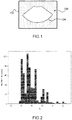
- Figure 1 shows scan-converted ultrasound data 102 in a rectangular scan-converted space.
- Scan lines are typically used to create viewable ultrasound data 102 (e.g. images or volumes) from raw data based on how the ultrasound data 102 was acquired (based on the acquisition procedure) which allows the data to be visualized in a true Cartesian domain where distances and angles are measurable.
- the raw data captured by an ultrasound probe is scan-converted with help of the scan lines to Cartesian coordinates to provide a "real life" view of the ultrasound data.
- the scan-converted ultrasound data 102 is typically stored in the scan-converted space (in Cartesian coordinates) and any analysis or data processing performed post-acquisition must typically be done in the scan-converted space.
- Scan-converted ultrasound data 102 in Cartesian coordinates typically contains meaningful data 104 in a cone-like shape surrounded by "empty" (or meaningless) data 106. Even though a significant proportion of the scan-converted ultrasound data 102 does not contain meaningful data 104, all of the scan-converted space needs to be stored due to the nature of image data storage (typically a bitmap of image) in the Cartesian coordinates.
- 3D scan-converted ultrasound volumes typically contain significant proportions of empty data 106 (black voxels) which are not required for clinical information but are required for the scan-converted ultrasound volume to be stored in Cartesian coordinates.
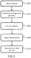
- Figure 2 shows a histogram of the percentage of meaningful data 104 in a large database of volumetric kidney acquisitions.
- the large database of volumetric kidney acquisitions contained 621 volumes.
- the ratio of the volume within the imaging cone (meaningful data 104) over the whole Cartesian volume was calculated for each volumetric kidney acquisition (in percentage %).
- the x-axis shows the ratio (in percentage % and in steps of 0.4%) of the meaningful data 104 to the total data stored in the scan-converted space.
- the y-axis shows the number of cases for each ratio range.
- the range of ratios is from 35.6% to 44.8% with the average ratio of meaningful data 104 being around 38%.
- the proportion of empty data 106 in the volumetric kidney acquisitions (which is only required for storing the data in Cartesian coordinates) is around 62%.
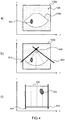
- Figure 3 shows a flow diagram of the method for performing a segmentation on 3D ultrasound volumes.
- an acquisition geometry can be estimated, step 304, if it is not known.
- the acquisition geometry may include estimating the scan lines of the ultrasound data and finding the optical center and mechanical center of the acquisition process.
- Estimating the acquisition geometry is based on estimating how the ultrasound data was acquired. For example, if an ultrasound volume was obtained with a phased array ultrasound probe rotated around the skin of a subject, the ultrasound data will have a minimum depth and a maximum depth (relative to the ultrasound transducer array), an optical center (where the ultrasound transducers reside), a mechanical center (where the rotor of the ultrasound probe resides), an angle of view (based on the angle of an ultrasound image obtained by the ultrasound probe) and an angle of sweep (based on the rotation of the ultrasound probe around the skin by the rotor of the ultrasound probe). These quantities of acquisition geometry can be estimated from the ultrasound data. With the acquisition geometry, the volume can be "de-scanned", step 306.
- De-scanning is the process of "un-doing" the scan conversion process, in order to get rid of as much empty data as possible. This can be done by choosing a coordinate system which simulates the acquisition process.
- the Toroidal coordinate system is a good approximation, as it requires two centers (equating to the optical center and mechanical center of the acquisition in ultrasound imaging).
- the spherical coordinate system could also be used, using the assumption that both centers (mechanical and optical) are in the same point in space.
- the Polar coordinate system can be chosen, as a cone can be fully described in the Polar coordinate system without the need of any empty data.
- a segmentation algorithm can be applied, step 308, to the volume in order to segment a target anatomy.
- Working in the de-scanned coordinate system for the segmentation process is more powerful and provides better performance of automatic segmentation.
- the target anatomy may include one or more of organs, blood vessels, heart chambers, bones, muscles etc.
- the segmentation algorithm would have also been trained with de-scanned volumes.
- the segmentation data can then be returned to the Cartesian coordinate system (re-scanned), step 310, such that viewing the volume (e.g. on a display) is more intuitive for a clinician.
- the original volume is for example shown with the segmentation data having been re-scanned.
- the image data of the original volume could be re-scanned together with the segmentation data, but it is preferred to use the original image data (without de-scanning and re-scanning).
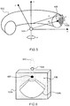
- Figure 4 shows an example of how a scan-converted ultrasound image 102a may be de-scanned.
- Figure 4 a) shows the scan-converted ultrasound image 102a in Cartesian coordinates.
- the empty data 106 is needed in order to store the meaningful image 104a in a rectangular format, such as in a bitmap.
- a target anatomy 402 is shown to aid in explaining how the de-scan process works.
- Figure 4 b shows the scan-converted ultrasound image 102a interpolated with imaging lines 404. It may be that the imaging lines 404 are stored with the scan-converted ultrasound image 102a. However, in most cases, stored scan-converted ultrasound data 102 does not contain data on the imaging lines 404. In this case, the imaging lines 404 can be estimated from the scan-converted ultrasound images 102a. Two imaging lines 404 can be estimated from the side edges from the scan-converted ultrasound image 102a. From these imaging lines 404, an optical center 406 can be estimated and further imaging lines 404 may be constructed. An angle of view can also be estimated from the imaging lines 404 as the angle between the two furthest imaging lines 404 determined at the edges.
- Figure 4 c) shows a de-scanned ultrasound image 408 in Polar coordinates, where the radial component is based on the distance of each data point from the optical center 406 found in Figure 4 b) .
- the angular component of each data point can also be found by measuring the angle between an imaging line containing the data point and an edge imaging line for the scan-converted ultrasound image 102a in the Cartesian coordinates.
- the target anatomy 402 represents a higher proportion of the overall data (compared to the scan-converted ultrasound image 102a).
- Figure 5 shows part of a toroid 502 in the Cartesian and Toroidal coordinate systems.
- the transform is inspired from the acquisition process as it performs a kind of de-scan conversion, which may be seen as a dedicated pre-processing step for a segmentation algorithm.
- a Cartesian to Toroidal transformation can be applied to the scan-converted ultrasound data 102 in order to mimic ultrasound lines that could have generated a similar volume.
- the Toroidal coordinate system can be used to represent meaningful 3D ultrasound data 104b.
- 3D ultrasound data is typically determined from many 2D ultrasound images.
- An optical center 406 can be obtained for the 2D ultrasound images (at least two). The optical centers will create a section of circle, and the center of the circle is the mechanical center 504.
- Equations (1) and (2) can be used to transform a volume from Cartesian coordinates into Toroidal coordinates.
- a point is named ( x, y, z).
- the equations calculate ( r, ⁇ , ⁇ ) as a function of ( x, y, z ) where ( r, ⁇ , ⁇ ) ⁇ [ R, ⁇ , ⁇ ].
- [ R , ⁇ , ⁇ ] are the ranges of values of the parameters selected for de-scan. This defines the sixe of the de-scanned volume that is computed as input to the segmentation training and testing algorithm.
- the de-scan can thus be applied with multiple choices of these parameters. This means that the method can be scaled to the available memory on computers when learning the network for a given organ.
- a 3D dataset of dimension ( R, ⁇ , ⁇ ) is obtained, where each voxel carries significant information.
- the minimum and maximum value of r can be calculated from the minimum depth and maximum depth of acquisition respectively, the value of ⁇ can be calculated from the angle of view and the value of ⁇ can be calculated from the angle of sweep.
- Figure 6 shows a scan-converted ultrasound volume 102b in a scan-converted space.
- the white cone represents meaningful data 104b, while the dotted space represents zero values which do not code any useful information 106.
- the larger dotted circle outside the scan-converted space represents the mechanical center 504 and the smaller black circle represents the optical center 406 in an A-plane.
- the parameters of the acquisition geometry are estimated. They represent: the center of the A-plane imaging beams (optical center 406), the minimum and maximum depth of imaging, the angle of view in A-plane, the center of the sweep for imaging other planes (mechanical center 504), and the corresponding sweep angle.
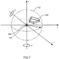
- Figure 7 shows an ultrasound volume 104b in spherical coordinates.
- the ultrasound volume 104b can be represented in Spherical coordinates when the optical center 406 and the mechanical center 504 are both in the same place (or can be approximated as being in the same place).
- the ultrasound volume 104b can thus be fully defined in the spherical coordinate system without the need of empty data.
- Figure 8 shows organ segmentations 806 in the de-scanned coordinate system and in the acquisition coordinate system.
- the left hand side images 802 show ultrasound images from an ultrasound volume with kidney segmentations in Cartesian coordinates.
- the right hand side images 804 show de-scanned ultrasound images from an ultrasound volume after the ultrasound volume has been converted into the de-scanned coordinate system with the corresponding de-scanned segmentations.
- the horizontal axis represents the radius r and the vertical axis represents the poloidal angle ⁇ of the Toroidal coordinate system.
- the de-scanned segmentation is generated for ground-truth segmentations and may be used for network training.
- Data augmentation is a method used to create large quantities of data from an initial small size of data.
- geometric transformations e.g. rotations and translations
- color transformations e.g. grayscale transformation
- the de-scanned ultrasound data in the Toroidal coordinate system allows for more intuitive and less error prone geometric transformations to create large databases for training.
- data biases must be avoided if possible (e.g. shape of data).
- shape of data In scan-converted ultrasound data, the cone shape containing the meaningful data is a source of data bias for the segmentation algorithm.
- the segmentation algorithm is also trained with the empty (meaningless) data which may cause the segmentation algorithm to ignore certain sections of the data in future segmentations or to look for certain patterns of empty data.
- De-scanned ultrasound data (e.g. in the Toroidal coordinate system) can be fully described without the need of empty data for storage, thus the data bias due to the empty data is removed.
- the algorithm may be any type of standard deep-learning approach such as U-Net segmentation.
- the segmented ultrasound data may be converted back to the Cartesian coordinate system.
- the acquisition geometry parameters are re-used in the inverse transformation, in order to convert the segmentation mask from, for example, the Toroidal coordinate system back to the image Cartesian coordinate system.
- Figure 9 shows the results of organ segmentations 908 in the de-scanned coordinate system 904 and in the Cartesian coordinate system 902. The same cases are shown, segmented without the coordinate transformation on the left hand side images 902, and segmented with the coordinate transformation to the de-scan domain on the right hand side images 904.
- the approximate ground truth 906 is shown in black circles and the segmentation algorithm result 908 are shown by white perimeters.
- the stripped arrows 910 show segmentation leaks in the results without the de-scan transformation in the scan-converted ultrasound images 902.
- the corresponding arrows 912 are shown in the images with the de-scan transformation, showing that segmentation leaks are significantly reduced in the de-scanned ultrasound images 904.
- kidney 69 volumes
- Abdomen 40 volumes
- Mean Dice in de-scanned images 0,87 0,94
- Mean Dice in scan-converted images 0,83 0,83
- the system makes use of processor to perform the data processing.
- the processor can be implemented in numerous ways, with software and/or hardware, to perform the various functions required.
- the processor typically employs one or more microprocessors that may be programmed using software (e.g., microcode) to perform the required functions.
- the processor may be implemented as a combination of dedicated hardware to perform some functions and one or more programmed microprocessors and associated circuitry to perform other functions.
- circuitry examples include, but are not limited to, conventional microprocessors, application specific integrated circuits (ASICs), and field-programmable gate arrays (FPGAs).
- ASICs application specific integrated circuits
- FPGAs field-programmable gate arrays
- the processor may be associated with one or more storage media such as volatile and non-volatile computer memory such as RAM, PROM, EPROM, and EEPROM.
- the storage media may be encoded with one or more programs that, when executed on one or more processors and/or controllers, perform the required functions.
- Various storage media may be fixed within a processor or controller or may be transportable, such that the one or more programs stored thereon can be loaded into a processor.
- a single processor or other unit may fulfill the functions of several items recited in the claims.
- a computer program may be stored/distributed on a suitable medium, such as an optical storage medium or a solid-state medium supplied together with or as part of other hardware, but may also be distributed in other forms, such as via the Internet or other wired or wireless telecommunication systems.
- a suitable medium such as an optical storage medium or a solid-state medium supplied together with or as part of other hardware, but may also be distributed in other forms, such as via the Internet or other wired or wireless telecommunication systems.
Landscapes
- Engineering & Computer Science (AREA)
- Computer Vision & Pattern Recognition (AREA)
- Theoretical Computer Science (AREA)
- General Physics & Mathematics (AREA)
- Physics & Mathematics (AREA)
- Medical Informatics (AREA)
- Quality & Reliability (AREA)
- Radiology & Medical Imaging (AREA)
- Nuclear Medicine, Radiotherapy & Molecular Imaging (AREA)
- Health & Medical Sciences (AREA)
- General Health & Medical Sciences (AREA)
- Software Systems (AREA)
- Ultra Sonic Daignosis Equipment (AREA)
- Image Processing (AREA)
Priority Applications (6)
| Application Number | Priority Date | Filing Date | Title |
|---|---|---|---|
| EP20290039.5A EP3907700A1 (de) | 2020-05-07 | 2020-05-07 | Ultraschalldatensegmentierung |
| CN202180033568.1A CN115516504B (zh) | 2020-05-07 | 2021-04-28 | 超声数据分割 |
| JP2022567344A JP7771085B2 (ja) | 2020-05-07 | 2021-04-28 | 超音波データのセグメンテーション |
| US17/923,016 US12450751B2 (en) | 2020-05-07 | 2021-04-28 | Ultrasound data segmentation |
| EP21720540.0A EP4147203B1 (de) | 2020-05-07 | 2021-04-28 | Ultraschalldatensegmentierung |
| PCT/EP2021/061038 WO2021224073A1 (en) | 2020-05-07 | 2021-04-28 | Ultrasound data segmentation |
Applications Claiming Priority (1)
| Application Number | Priority Date | Filing Date | Title |
|---|---|---|---|
| EP20290039.5A EP3907700A1 (de) | 2020-05-07 | 2020-05-07 | Ultraschalldatensegmentierung |
Publications (1)
| Publication Number | Publication Date |
|---|---|
| EP3907700A1 true EP3907700A1 (de) | 2021-11-10 |
Family
ID=71105430
Family Applications (2)
| Application Number | Title | Priority Date | Filing Date |
|---|---|---|---|
| EP20290039.5A Withdrawn EP3907700A1 (de) | 2020-05-07 | 2020-05-07 | Ultraschalldatensegmentierung |
| EP21720540.0A Active EP4147203B1 (de) | 2020-05-07 | 2021-04-28 | Ultraschalldatensegmentierung |
Family Applications After (1)
| Application Number | Title | Priority Date | Filing Date |
|---|---|---|---|
| EP21720540.0A Active EP4147203B1 (de) | 2020-05-07 | 2021-04-28 | Ultraschalldatensegmentierung |
Country Status (5)
| Country | Link |
|---|---|
| US (1) | US12450751B2 (de) |
| EP (2) | EP3907700A1 (de) |
| JP (1) | JP7771085B2 (de) |
| CN (1) | CN115516504B (de) |
| WO (1) | WO2021224073A1 (de) |
Cited By (1)
| Publication number | Priority date | Publication date | Assignee | Title |
|---|---|---|---|---|
| EP4483815A1 (de) * | 2023-06-28 | 2025-01-01 | Koninklijke Philips N.V. | System und verfahren zur abstimmung von ultraschallbildgebung |
Citations (2)
| Publication number | Priority date | Publication date | Assignee | Title |
|---|---|---|---|---|
| US20040138560A1 (en) * | 2002-12-02 | 2004-07-15 | Gianluca Paladini | Real-time scan conversion and rendering of ultrasound data |
| CN107909585B (zh) * | 2017-11-14 | 2020-02-18 | 华南理工大学 | 一种血管内超声影像的血管中内膜分割方法 |
Family Cites Families (13)
| Publication number | Priority date | Publication date | Assignee | Title |
|---|---|---|---|---|
| JP3355298B2 (ja) * | 1998-02-05 | 2002-12-09 | 松下電器産業株式会社 | 超音波診断装置 |
| US6723050B2 (en) * | 2001-12-19 | 2004-04-20 | Koninklijke Philips Electronics N.V. | Volume rendered three dimensional ultrasonic images with polar coordinates |
| JP2004141514A (ja) | 2002-10-28 | 2004-05-20 | Toshiba Corp | 画像処理装置及び超音波診断装置 |
| KR100751852B1 (ko) * | 2003-12-31 | 2007-08-27 | 주식회사 메디슨 | 대상체의 3차원 초음파 데이터를 이용하여 그 단면을디스플레이하는 장치 및 방법 |
| JP5430203B2 (ja) | 2009-03-31 | 2014-02-26 | キヤノン株式会社 | 画像処理装置、画像処理方法 |
| JP5599683B2 (ja) | 2010-09-07 | 2014-10-01 | 株式会社日立メディコ | 医用画像処理装置、医用画像処理方法 |
| US11109835B2 (en) * | 2011-12-18 | 2021-09-07 | Metritrack Llc | Three dimensional mapping display system for diagnostic ultrasound machines |
| US8724878B2 (en) * | 2012-01-12 | 2014-05-13 | General Electric Company | Ultrasound image segmentation |
| KR20140035747A (ko) | 2012-09-14 | 2014-03-24 | 삼성전자주식회사 | 초음파 영상 장치 및 그 제어방법 |
| JP6644795B2 (ja) * | 2015-01-06 | 2020-02-12 | コーニンクレッカ フィリップス エヌ ヴェKoninklijke Philips N.V. | 解剖学的オブジェクトをセグメント化する超音波画像装置及び方法 |
| CN104915924B (zh) * | 2015-05-14 | 2018-01-26 | 常州迪正雅合电子科技有限公司 | 一种自动实现三维超声图像定标的方法 |
| CN110327073B (zh) * | 2019-08-01 | 2022-03-11 | 无锡海斯凯尔医学技术有限公司 | 数字扫描变换方法、装置、设备及可读存储介质 |
| WO2021184075A1 (en) * | 2020-03-19 | 2021-09-23 | Volsonics Pty Ltd | Method and system for automatic 3d-fmbv measurements |
-
2020
- 2020-05-07 EP EP20290039.5A patent/EP3907700A1/de not_active Withdrawn
-
2021
- 2021-04-28 EP EP21720540.0A patent/EP4147203B1/de active Active
- 2021-04-28 US US17/923,016 patent/US12450751B2/en active Active
- 2021-04-28 JP JP2022567344A patent/JP7771085B2/ja active Active
- 2021-04-28 CN CN202180033568.1A patent/CN115516504B/zh active Active
- 2021-04-28 WO PCT/EP2021/061038 patent/WO2021224073A1/en not_active Ceased
Patent Citations (2)
| Publication number | Priority date | Publication date | Assignee | Title |
|---|---|---|---|---|
| US20040138560A1 (en) * | 2002-12-02 | 2004-07-15 | Gianluca Paladini | Real-time scan conversion and rendering of ultrasound data |
| CN107909585B (zh) * | 2017-11-14 | 2020-02-18 | 华南理工大学 | 一种血管内超声影像的血管中内膜分割方法 |
Non-Patent Citations (2)
| Title |
|---|
| LO VERCIO LUCAS ET AL: "Assessment of image features for vessel wall segmentation in intravascular ultrasound images", INTERNATIONAL JOURNAL OF COMPUTER ASSISTED RADIOLOGY AND SURGERY, SPRINGER, DE, vol. 11, no. 8, 25 January 2016 (2016-01-25), pages 1397 - 1407, XP036013989, ISSN: 1861-6410, [retrieved on 20160125], DOI: 10.1007/S11548-015-1345-4 * |
| NICOLAS TOUSSAINT ET AL: "Weakly Supervised Localisation for Fetal Ultrasound Images", ARXIV.ORG, CORNELL UNIVERSITY LIBRARY, 201 OLIN LIBRARY CORNELL UNIVERSITY ITHACA, NY 14853, 2 August 2018 (2018-08-02), XP080901171 * |
Cited By (2)
| Publication number | Priority date | Publication date | Assignee | Title |
|---|---|---|---|---|
| EP4483815A1 (de) * | 2023-06-28 | 2025-01-01 | Koninklijke Philips N.V. | System und verfahren zur abstimmung von ultraschallbildgebung |
| WO2025002957A1 (en) * | 2023-06-28 | 2025-01-02 | Koninklijke Philips N.V. | System and method for tuning ultrasound imaging |
Also Published As
| Publication number | Publication date |
|---|---|
| WO2021224073A1 (en) | 2021-11-11 |
| US20230360224A1 (en) | 2023-11-09 |
| EP4147203B1 (de) | 2025-01-15 |
| CN115516504B (zh) | 2026-02-03 |
| CN115516504A (zh) | 2022-12-23 |
| JP2023524543A (ja) | 2023-06-12 |
| JP7771085B2 (ja) | 2025-11-17 |
| US12450751B2 (en) | 2025-10-21 |
| EP4147203A1 (de) | 2023-03-15 |
Similar Documents
| Publication | Publication Date | Title |
|---|---|---|
| KR101565311B1 (ko) | 3 차원 심초음파 검사 데이터로부터 평면들의 자동 검출 | |
| Krucker et al. | Rapid elastic image registration for 3-D ultrasound | |
| CN108053433B (zh) | 一种基于物理对齐和轮廓匹配的多模态颈动脉mri配准方法 | |
| Jiang et al. | New approach to 3-D registration of multimodality medical images by surface matching | |
| US6687392B1 (en) | System for accurately obtaining a contour and/or quantitative information from an echo image with reduced manual operation | |
| EP2891133B1 (de) | Gekoppelte segmentierung in konventionellem 3d-ultraschall und kontrastverstärkten ultraschallbildern | |
| US8355553B2 (en) | Systems, apparatus and processes for automated medical image segmentation using a statistical model | |
| US20080242985A1 (en) | 3d ultrasound-based instrument for non-invasive measurement of amniotic fluid volume | |
| CN110338841A (zh) | 三维成像数据的显示处理方法和三维超声成像方法及系统 | |
| US7639895B2 (en) | Registering ultrasound image data and second image data of an object | |
| CN105025803A (zh) | 从多个三维视图对大对象的分割 | |
| CN119006414B (zh) | 一种踝关节距骨软骨分割及厚度测量方法 | |
| CN117689567B (zh) | 一种超声波图像扫描方法及装置 | |
| EP4147203B1 (de) | Ultraschalldatensegmentierung | |
| CN112766332A (zh) | 医学影像检测模型训练方法、医学影像检测方法及装置 | |
| EP0854442B1 (de) | Verfahren und Vorrichtung zur Darstellung von Oberflächen aus volumetrischen Daten | |
| CN1399763A (zh) | 使用统计曲率分析的三维测量 | |
| Freitas et al. | Automatic multi-view pose estimation in focused cardiac ultrasound | |
| Kim et al. | Mutual information for automated multimodal image warping | |
| Pavani et al. | Quality metric for parasternal long axis b-mode echocardiograms | |
| CN111166373B (zh) | 一种定位注册方法、装置和系统 | |
| JP2591788B2 (ja) | Mri画像の臓器領域抽出方法 | |
| EP4571645B1 (de) | Bestimmung eines standorts, an dem ein vorgegebenes merkmal in medizinischen bilddaten dargestellt wird | |
| CN101261735A (zh) | 在高维空间中检测对象的系统和方法 | |
| CN115886876B (zh) | 胎儿姿态的评估方法、超声成像方法及超声成像系统 |
Legal Events
| Date | Code | Title | Description |
|---|---|---|---|
| PUAI | Public reference made under article 153(3) epc to a published international application that has entered the european phase |
Free format text: ORIGINAL CODE: 0009012 |
|
| STAA | Information on the status of an ep patent application or granted ep patent |
Free format text: STATUS: THE APPLICATION HAS BEEN PUBLISHED |
|
| AK | Designated contracting states |
Kind code of ref document: A1 Designated state(s): AL AT BE BG CH CY CZ DE DK EE ES FI FR GB GR HR HU IE IS IT LI LT LU LV MC MK MT NL NO PL PT RO RS SE SI SK SM TR |
|
| B565 | Issuance of search results under rule 164(2) epc |
Effective date: 20201009 |
|
| STAA | Information on the status of an ep patent application or granted ep patent |
Free format text: STATUS: THE APPLICATION IS DEEMED TO BE WITHDRAWN |
|
| 18D | Application deemed to be withdrawn |
Effective date: 20220511 |