EP3907714B1 - Kondensationsverhinderung in einem ansaugrauchmeldesystem - Google Patents
Kondensationsverhinderung in einem ansaugrauchmeldesystem Download PDFInfo
- Publication number
- EP3907714B1 EP3907714B1 EP20382380.2A EP20382380A EP3907714B1 EP 3907714 B1 EP3907714 B1 EP 3907714B1 EP 20382380 A EP20382380 A EP 20382380A EP 3907714 B1 EP3907714 B1 EP 3907714B1
- Authority
- EP
- European Patent Office
- Prior art keywords
- detector unit
- smoke
- heater
- metallic layer
- light
- Prior art date
- Legal status (The legal status is an assumption and is not a legal conclusion. Google has not performed a legal analysis and makes no representation as to the accuracy of the status listed.)
- Active
Links
Images

Classifications
-
- G—PHYSICS
- G01—MEASURING; TESTING
- G01N—INVESTIGATING OR ANALYSING MATERIALS BY DETERMINING THEIR CHEMICAL OR PHYSICAL PROPERTIES
- G01N21/00—Investigating or analysing materials by the use of optical means, i.e. using sub-millimetre waves, infrared, visible or ultraviolet light
- G01N21/17—Systems in which incident light is modified in accordance with the properties of the material investigated
- G01N21/47—Scattering, i.e. diffuse reflection
- G01N21/49—Scattering, i.e. diffuse reflection within a body or fluid
- G01N21/53—Scattering, i.e. diffuse reflection within a body or fluid within a flowing fluid, e.g. smoke
- G01N21/532—Scattering, i.e. diffuse reflection within a body or fluid within a flowing fluid, e.g. smoke with measurement of scattering and transmission
-
- G—PHYSICS
- G08—SIGNALLING
- G08B—SIGNALLING SYSTEMS, e.g. PERSONAL CALLING SYSTEMS; ORDER TELEGRAPHS; ALARM SYSTEMS
- G08B17/00—Fire alarms; Alarms responsive to explosion
- G08B17/10—Actuation by presence of smoke or gases, e.g. automatic alarm devices for analysing flowing fluid materials by the use of optical means
-
- G—PHYSICS
- G08—SIGNALLING
- G08B—SIGNALLING SYSTEMS, e.g. PERSONAL CALLING SYSTEMS; ORDER TELEGRAPHS; ALARM SYSTEMS
- G08B29/00—Checking or monitoring of signalling or alarm systems; Prevention or correction of operating errors, e.g. preventing unauthorised operation
- G08B29/18—Prevention or correction of operating errors
-
- G—PHYSICS
- G01—MEASURING; TESTING
- G01N—INVESTIGATING OR ANALYSING MATERIALS BY DETERMINING THEIR CHEMICAL OR PHYSICAL PROPERTIES
- G01N2201/00—Features of devices classified in G01N21/00
- G01N2201/02—Mechanical
- G01N2201/023—Controlling conditions in casing
- G01N2201/0238—Moisture monitoring or controlling
Definitions
- the present invention relates to reducing the formation of condensation within a detector unit of an aspirating smoke detection system.
- An aspirating smoke detection system is a system used in active fire protection, comprising a central detector unit which draws air from a room which is being monitored through a network of pipes.
- Aspirating smoke detection systems can detect smoke long before it is visible to the naked eye, and thus such systems are often referred to as high sensitivity smoke detectors (HSSDs).
- HSSDs high sensitivity smoke detectors
- the aspirating smoke detection system comprises a fan unit or blower that is used to draw in air from the monitored area through the network of pipes. A portion of this air (typically around 10%) is then passed into a sampling chamber of the central detector unit where it is used to determine whether or not smoke is present.
- the sampling chamber is typically part of a nephelometer that detects the presence of smoke particles suspended in air by detecting the light scattered by the smoke particles in the chamber.
- a nephelometer measures suspended particulates by directing a light beam (e.g. using a laser) through the sample chamber to a light absorbing receiver positioned opposite in the chamber, which absorbs any light incident upon it.
- a light detector e.g. a photodiode
- the light detector detects light scattered from the light beam by smoke particles present in the air of the sampling chamber.
- the sampling chamber often has a mirrored interior surface that is arranged to reflect scattered light to the light detector. Particle density can be calculated as a function of the light reflected into the detector from the particles.
- the temperature of the detector unit usually remains similar to that of the sample air (i.e. the temperature of the air drawn into the system from a room to be monitored).
- sample air i.e. the temperature of the air drawn into the system from a room to be monitored.
- aspirating smoke detection systems often have to deal with a wide range of sample air temperatures, as the temperature of the sample air is directly dependent on the temperature of the room being monitored.
- sample air temperature increases abruptly inside the detector unit, water condenses along the air flow path on the colder components of the system. This becomes problematic in the detector unit and in particular it is problematic inside of the sampling chamber because the transmittal and reflection of light from the light beam is modified (due to the presence of a layer of water and different Fresnel coefficients). This can reduce the accuracy of the reading from the detector unit.
- a heater in the aspirating smoke detection system near the inlet to the central detector unit where air from the monitored area is drawn into the system.
- a heater is often coupled to the fan unit or blower mentioned above to heat the air as it is taken into the unit.
- the heater heats all of the air taken into the system in order to maintain a substantially constant air temperature (higher than the ambient temperature of the monitored area) and thus avoid or reduce an abrupt change in temperature inside of the detector unit and the resultant formation of condensation.
- Such a heater typically reduces the flow rate of air through the detection system in order for the air to be heated for a sufficient amount of time.
- US 7301640 B2 discloses a non-dispersive infrared gas detector including a heater for eliminating condensation.
- the present invention provides a smoke detector unit for an aspirating smoke detection system as claimed in claim 1.
- the smoke detector unit comprises: a housing that defines a detection chamber, wherein the housing comprises a metallic layer optically exposed to the detection chamber; a laser arranged to direct a beam of light through the detection chamber; a photodiode arranged to detect light scattered from the beam of light; and a heater positioned proximate the metallic layer and outside of the detection chamber, wherein the metallic layer is configured to conduct heat from the heater.
- the metallic layer and laser are configured to conduct heat from the heater to a lens of the laser in order to prevent or reduce the formation of condensation on the lens of the laser and on the metallic layer.
- a receiver is arranged to absorb light from the laser that is not scattered from the beam of light, wherein the metallic layer is configured to conduct heat from the heater to the receiver in order to prevent or reduce the formation of condensation at the receiver.
- the metallic layer that forms part of the walls of the detection chamber can be heated more directly to avoid condensation.
- a substantially even, heated temperature of the layer will be maintained, which prevents condensation from forming on the metallic layer.
- the metallic layer can conduct the heat efficiently to other parts of the detector unit, including the air in the detection chamber.
- the metallic layer can conduct heat from the heater to the laser, which may ensure the laser is heated to prevent condensation from forming on/within the laser. Condensation on the lenses of the laser is problematic because, due to the nanometre wavelengths of light emitted by the laser, the condensation can cause refraction of the transmitted light from the laser. This can cause light from the laser to be detected as scattered light because it is instead reflected by the metallic layers to the photodetector. This can result in light from the laser being detected as scattered light and a false detection of smoke.
- the metallic layer can conduct heat from the heater to the receiver in order to prevent or reduce the formation of condensation at or on the receiver. It will be appreciated that this is advantageous as condensation on the receiver can also result in a false detection of smoke as this may reflect or scatter light, thus preventing it from being absorbed by the receiver.
- the metallic layer may also be arranged to conduct heat to the entire surface of the metallic layer.
- the detection chamber and metallic layer may be evenly heated and condensation on the metallic layer may be reduced or prevented.
- Condensation on the metallic layer is also significant as this is designed to reflect scattered light to the photodiode and the presence of condensation alters this reflection following similar reasoning as outlined above. This can reduce the effectiveness of the detector unit in detecting scattered light, thus reducing the ability/sensitivity of the detector in detecting smoke.
- the detector unit may be arranged to operate as a nephelometer in order to detect the presence of smoke.
- the metallic layer may have already been present in a pre-existing detector unit and the heater may be retrofitted to such a pre-exiting detector unit in order to form a detector unit according to the first aspect.
- the housing may be formed from two parts, which may comprise a dome, or hemispherical portion and a top portion.
- the dome portion may be attached to the cover portion so that the housing encloses the detection chamber and the detection chamber may be optically sealed, preventing any light entering from an outside environment.
- the dome portion may comprise the metallic layer and the metallic layer may be positioned on an inner surface of the dome portion.
- the cover portion may also comprise a similar metallic layer on its inner surface.
- the respective metallic layers of the dome portion and the cover potion may be in contact with one another at a top edge of the detection chamber.
- the cover portion and dome portion may be formed from a plastic material, with the metallic layer(s) formed thereon. Both the cover portion and dome portion may be thermally conductive.
- the metallic layer(s) may be arranged to reflect light scattered from the beam of light to the photodiode.
- the laser may be seated within a recess in the top portion.
- the housing may be configured to conduct heat from the heater to the laser via the metallic layer and the top portion.
- a heater may be adjacent the cover portion or laser and heat may be conducted to the metallic layer.
- any of the components described herein as being fixed to one another, proximate to one another or adjacent to one another may be attached using thermally conductive adhesive.
- the receiver is a light absorber and is configured to absorb any light incident upon it.
- the receiver may be positioned adjacent to an exterior surface of the housing, particularly the dome portion, and may be positioned behind a small hole in the metallic layer.
- the photodiode may be positioned within the detection chamber.
- the photodiode may be set to one side of the light beam such that it does not receive light emitted directly by the laser. This position of the photodiode may be the optimum positon to detect reflected light from the metallic layer.
- the metallic layer may be configured to conduct heat from the heater to the photodiode in order to prevent or reduce the formation of condensation at or on the photodiode. It will be appreciated that this is advantageous as condensation on the photodiode can reduce the sensitivity of the photodiode in detecting scattered light.
- the heater may comprise a plurality of heating elements, and these elements may be cables or tapes.
- the heating elements or tapes may be spaced equally apart from one another. Such heaters may provide heat more evenly to the metallic layer.
- the heating elements may extend around at least part of the metallic layer.
- the heating elements may be adjacent the dome portion and may extend across at least part of the surface the dome portion.
- the heating elements may extend around at least part of a circumference of a sector of the dome portion. Such arrangements can heat the metallic layer evenly.
- the detector unit may comprise a temperature sensor for measuring a temperature of one or more components of the detector unit.
- the heater itself may comprise the temperature sensor.
- the temperature sensor may be arranged to measure a temperature of the heater, a temperature of air inside of the detection chamber, a temperature of the metallic layer and/or a temperature of the laser.
- the detector unit may be configured to adjust a heat output of the heater based at least in part on the measured temperature.
- the heater is configured to self-regulate its heating output.
- the heater may comprise one or more self-regulating heating cables.
- the heating elements may comprise Positive Temperature Coefficient ("PTC") heating elements.
- PTC Positive Temperature Coefficient
- the heater may be configured to maintain any of these temperatures above a predetermined value.
- the predetermined value may be higher than an expected operating range of air temperatures; in particular, an expected range of air temperatures in a space to be monitored. This may be above 25°C, above 27°C or even above 30°C.
- the heater may have its heating output adjusted in any of the ways described herein using a controller.
- the detector unit may comprise a blower arranged to draw an air flow from a space to be monitored into the smoke detector unit.
- the blower may be arranged to divert a portion of the air flow to the detection chamber of the detector unit.
- the portion of the air flow that is diverted to the detection chamber may be 50% or less of the total air flow drawn from the space to be monitored, 25% or less, 20% or less or even 15% or less.
- the portion of air flow that is diverted to the sample chamber may be at least 5% of the total air flow drawn from the space to be monitored, or at least 10%.
- the present invention provides an aspirating smoke detection system as claimed in claim 10.
- the aspirating smoke detection system comprises: the detector unit according to the first aspect, wherein the detector unit may comprise a blower arranged to draw an air flow from a space to be monitored into the aspirating smoke detection system; and piping arranged to direct the air flow through the smoke detection system, wherein a portion of the air flow is diverted to the detection chamber of the detector unit.
- the piping may comprise an inlet fluidly connected to the space to be monitored.
- the inlet may comprise a plurality of sampling holes along a length of the piping.
- the space to be monitored may be a part or all of a building, a vehicle or a room.
- the portion of air flow that is diverted to the sample chamber may be 50% or less of the total air flow drawn from the space to be monitored, preferably 25% or less, more preferably 20% or less and even more preferably 15% or less.
- the portion of air flow that is diverted to the sample chamber may be at least 5% of the total air flow drawn from the space to be monitored, preferably at least 10%.
- the system may be configured to allow the portion of air to be adjusted.
- the detector unit according to the first aspect or the system according to the second aspect may comprise a controller.
- the controller may be connected to any one or more of the indicators, flow sensors, temperature sensors, heaters or blowers mentioned herein.
- the controller may be configured to adjust the heat output of the heaters in any manner discussed herein.
- the detector unit according to the first aspect or the system according to the second aspect may comprise a buck boost regulator with overcurrent protection and may also comprise a power source.
- the power source may be a mains power supply, a battery or a capacitor.
- the power source may be arranged to supply power to the detector unit and/or the controller via the buck boost regulator.
- the buck boost regulator may function to protect against overcurrent and ensure a stable power supply to the detector unit.
- the detector unit according to the first aspect or the system according to the second aspect may comprise a temperature sensor for measuring a temperature of the space to be monitored and the heat output of the heater may be at least in part on this measured temperature.
- the detector unit according to the first aspect or the system according to the second aspect may comprise a flow sensor.
- the flow sensor may measure a flow rate of air drawn into system, through the blower, through the system and/or diverted through the detector unit.
- the flow sensor may be incorporated into the blower.
- the heat output of the heater may be adjusted based at least in part on any of the measured flow rates and/or temperatures described herein.
- the detector unit according to the first aspect or the system according to the second aspect may comprise an indicator.
- the indicator may be arranged to indicate to a user any one or a combination of the following: any of the measured temperatures described herein; a heat output of the heater; a presence of condensation; a presence of smoke; or any of the measured rates of air flow described herein.
- the detector unit according to the first aspect or the system according to the second aspect may comprise a control panel and/or display for a user to operate the system and adjust the heat output by the heater or to adjust any of the flow rates.
- the control panel may comprise any of the indicators mentioned above.
- the detector unit according to the first aspect or the system according to the second aspect may comprise an alarm that is triggered when smoke is detected.
- the present invention provides a method of reducing or preventing the formation of condensation within a detector unit of an aspirating smoke detection system, as claimed in claim 11.
- the method comprises: applying heat from a heater to a metallic layer of a detection chamber of the detector unit in order to reduce or prevent the formation of condensation on one or more of the metallic layer and a lens of a laser of the detection unit.
- the detector unit is a detector unit according to the first aspect including any of the optional features described herein.
- the method may comprise measuring a temperature of the detector unit, heater, laser, air in the space to be measured, air in the piping and/or air in the detection chamber; and adjusting the output of heat from the heater based at least in part on the measured temperature.
- the measuring of the temperature(s) may be performed using any of the temperature sensors described above in relation to the first and second aspect.
- the method may comprise adjusting the output of heat from the heater based at least in part on any measured temperature described herein.
- the method may comprise adjusting the output of heat from the heater based at least in part on any measured flow rate described herein.
- the measuring of flow rate(s) may be performed using any of the flow rate sensors described above in relation to the first and second aspect.
- the adjusting of the output of heat from the heater may be carried out automatically.
- the adjusting of output of heat from the heater may be performed by a self-regulating heater as previously discussed.
- the output of heat from the heater may be performed using the above mentioned controller described in relation to the first and second aspect.
- the method may comprise heating the detector unit using the heater to a predetermined temperature.
- the predetermined temperature may be a temperature higher than that of air in the space to be monitored, or higher than an expected range of temperatures for air in the space to be monitored.
- the heating cables may be arranged to maintain a temperature of the detector unit to be above 25°C, above 27°C or even above 30°C.
- the method may comprise always applying at least some heat output from the heater, regardless of measured temperature(s).
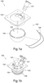
- a smoke detector 100 is shown.
- the smoke detector 100 comprises a housing 102, and an interior of the housing 102 defines a detection chamber 105.
- the housing 102 in the illustrated embodiment is formed from two parts, comprising a cover part 103 and a dome part 104.
- the cover part 103 and the dome part 104 are each formed from plastic and have a metallic layer on their inner surface that is reflective and optically exposed to the detection chamber 105.
- the dome part 104 is attached to the cover part 103 so that the housing 102 encloses the detection chamber 105 and the detection chamber 105 is optically sealed, preventing any light entering from an outside environment.
- the respective metallic layers of the dome part 104 and the cover part 103 are in contact with one another at a top edge of the detection chamber 105.
- a laser 101 is positioned so as to direct a beam of light through the detection chamber 105.
- the laser 101 is seated within a recess of the cover part 103 and the head of the laser 101 passes through the cover part 103 into the detection chamber 105.
- a light absorber (not shown) is positioned opposite the laser 101 across the detection chamber 105 to receive the beam of light from the laser 101.
- the light absorber is positioned outside of the detection chamber 105, behind a small hole in the metallic layer of the dome part 104 that allows the passage of light.
- a photodetector such as a photodiode, is positioned at the top of the detection chamber 105 and is set to one side of the light beam, such that the photodetector does not receive light emitted directly by the laser 101, but can detect scattered light from within the detection chamber 105.
- the smoke detector 100 operates as a nephelometer in order to detect the presence of smoke particles suspended in air inside of the detection chamber 105 by detecting light scattered in the detection chamber 105.
- the laser 101 transmits a beam of light through the detection chamber 105 the hole in the metallic layer of the dome part 104 to the light absorbing receiver positioned opposite the laser 101.
- the detection chamber 105 If smoke particles are present in the detection chamber 105, then a portion of the light from the laser 101 is scattered by the smoke particles in the detection chamber 105. Because of the reflective metallic layers of the dome part 105 and cover portion 103 that are optically exposed to the detection chamber 105, the light that is scattered is reflected and the photodetector detects this reflected, scattered light.
- control electronics 107 may be installed on the cover portion 103 outside of the detection chamber 105. Upon detection of light by the photodetector above a threshold level, the control electronics 107 of the smoke detector 100 may determine that smoke is present within the detection chamber 105 and an operator may be informed and/or an alarm may be sounded.
- the smoke detector 100 further comprises a pair of heating elements 106, such as resistive heating cables or tapes.
- the heating elements 106 are adjacent to the exterior surface of the dome part 104.
- the heating elements 106 are each laid in a plane around a circumference the dome part 104, and are spaced apart from one another.
- a single heating element 106 may be used, which may for example follow a spiral path around the dome part 104.
- the heating elements 106 may comprise self-regulating heating cables, such as a positive temperature coefficient (PTC) heater, whereby a heating power output of the cable adjusts automatically in response to a temperature of the cable in order to maintain a substantially constant temperature.
- PTC positive temperature coefficient
- heat output from the heating elements 106 is conducted through the plastic of the dome part 104 and heats the metallic layer of the dome part 104.
- the metallic layers of the cover part 103 and dome part 104 they will maintain a substantially even, heated temperature, which prevents condensation from forming on their reflective inner surfaces.
- the metallic layers also conduct heat to the laser 101, and a body of the laser 101 in turn conducts the heat to a lens of the laser 101. This prevents condensation from forming on the lens of the laser 101.
- This configuration is advantageous because the most problematic areas for condensation to form in the smoke detector 100 are on lenses of the laser 101 and the inner reflective surfaces (i.e. the metal layers) of the detection chamber 105.
- Condensation on the lenses of the laser 101 is problematic because, due to the nanometre wavelengths of light emitted by the laser 101, the condensation can cause refraction of the transmitted light from the laser 101. This can cause light from the laser to be detected as scattered light because it misses the hole to the light absorber and is instead reflected by the metallic layers to the photodetector. This can result in a false detection of smoke. Condensation on the metallic layers is also problematic as these are designed to reflect light to the photodetector. The presence of condensation on the metallic layers can alter their Fresnel coefficients and reduce the reflection of scattered light. This in turn decreases the sensitivity of the smoke detector 100 when detecting smoke.
- the heating elements 106 By conducting heat from the heating elements 106 to each of these components and heating them to a temperature that is the same as or above an ambient temperature of a monitored space (i.e. the temperature of the air drawn into the smoke detector 100 from a space to be monitored), the formation of condensation on these components can be reduced or prevented as there is no longer a drastic temperature drop between the ambient air temperature and the temperature of these components.
- any heating of the above components will reduce the formation of condensation.
- these components are heated to a temperature above a temperature of a space being monitored by the smoke detector 100 (or above an anticipated range of ambient operating temperatures) to prevent the formation of condensation.
- Some existing detectors comprise metallic layers such has those described above.
- heating elements 106 as described above can be retrofitted to make use of the existing metallic layers to conduct heat.
- the system 200 comprises a detector unit 200a including a smoke detector 201 like that described above in relation to Figures 1a and 1b .
- a cross-section of the smoke detector 201 is shown on the left hand side of Figure 2 , along with two isometric views of the dome part 104 with the heating elements 106 attached.
- the aspirating smoke detection system 200 comprises an inlet 202 and outlet 203 that are fluidly connected to a space to be monitored 204 such as a room via piping around the monitored space.
- the detector unit 200a is fitted to the inlet 202 and the outlet 203 in order to connect it to pre-installed piping that goes around the monitored space, thus forming the aspirating smoke detection system 200.
- This allows for a single design of detector unit 200a to be utilised for a wide range of monitored spaces because the pre-installed piping around the monitored space can be designed for a particular space.
- the inlet 202 and the outlet 203 form part of an air flow system that further comprises piping 205 fluidly connecting the inlet 202 to a blower unit 206, the smoke detector 201, and the outlet 203.
- the detector unit 200a comprises a power supply unit 208 and a buck boost regulator 209 with overcurrent protection electrically connected to the smoke detector 201 and a controller 207.
- the power supply unit 208 is arranged to be connected to mains power.
- the controller 207 is further connected to indicators 210, an air sensor 211 and the blower unit 206.
- the blower unit 206 draws air into the system 200 from the monitored space 204 via the inlet 202.
- the blower unit 206 will typically draw in significantly more air than can be processed by the smoke detector 201. Therefore, typically about 10 to 15% of the air from the blower unit 206 is diverted to the smoke detector 201 to be tested for the presence of smoke, with the remainder of the air being sent directly to the outlet 203.
- the portion of air diverted to the smoke detector 201 contains a range of air samples taken from the full flow. The remainder of the air and the diverted portion of air after it has been tested are eventually returned to the space to be monitored 204 via the outlet 203.
- Power is supplied to the smoke detector 201 and the controller 207 from the power supply unit 208 via the buck boost regulator 209.
- the buck boost regulator 209 functions to protect against overcurrent and ensures a stable power supply to the smoke detector 201 and the controller 207. Power supplied to the smoke detector 201 is used by the laser 101, the heating elements 106 and the photodetector.
- the air sensor 211 measures a flow rate through the inlet 202.
- the air sensor 211 also measures the temperature of the air entering the inlet 202. These measurements are all received by the controller 207.
- the heating elements 106 are self-regulating as mentioned above in order to maintaining a substantially constant temperature of the smoke detector 201, ideally a temperature above the expected operating air temperature ranges of the system. For example, if the space to be monitored 104 is an office space having a typical temperature of about 25°C, the heating elements 106 may be arranged to maintain a temperature of about 30°C.
- the heating elements 106 may also comprise a temperature sensor that measures the temperature of the heating elements, the dome portion 104 or the metallic layers, where the measured temperature is received by the controller 207.
- the controller 207 may adjust the heat output of the heating elements 106 based at least in part on any of the rates of air flow or any of the measured temperatures described above.
Landscapes
- Physics & Mathematics (AREA)
- General Physics & Mathematics (AREA)
- Analytical Chemistry (AREA)
- Chemical & Material Sciences (AREA)
- Immunology (AREA)
- Biochemistry (AREA)
- General Health & Medical Sciences (AREA)
- Life Sciences & Earth Sciences (AREA)
- Health & Medical Sciences (AREA)
- Pathology (AREA)
- Business, Economics & Management (AREA)
- Emergency Management (AREA)
- Engineering & Computer Science (AREA)
- Computer Security & Cryptography (AREA)
- Fire-Detection Mechanisms (AREA)
- Investigating Or Analysing Materials By Optical Means (AREA)
Claims (11)
- Rauchdetektoreinheit (100; 200a) für ein Ansaugrauchdetektionssystem (200), wobei die Rauchdetektoreinheit (100; 200a) Folgendes umfasst:ein Gehäuse (102), das eine Detektionskammer (105) definiert, wobei das Gehäuse eine metallische Schicht umfasst, die der Detektionskammer (105) optisch ausgesetzt ist;einen Laser (101), der zum Leiten eines Lichtstrahls durch die Detektionskammer (105) angeordnet ist;eine Fotodiode, die zum Detektieren von Licht, das von dem Lichtstrahl gestreut wird, angeordnet ist; undeine Heizvorrichtung (106), die in der Nähe der metallischen Schicht und außerhalb der Detektionskammer positioniert ist, wobei die metallische Schicht zum Leiten von Wärme von der Heizvorrichtung (106) konfiguriert ist;wobei die metallische Schicht und der Laser (101) zum Leiten von Wärme von der Heizvorrichtung (106) zu einer Linse des Lasers (101) konfiguriert sind, um die Kondensationsbildung an der Linse des Lasers (101) und an der metallischen Schicht zu verhindern oder zu verringern; und/oderwobei ein Empfänger zum Absorbieren von Licht von dem Laser (101), das nicht von dem Lichtstrahl gestreut wird, angeordnet ist, und wobei die metallische Schicht zum Leiten von Wärme von der Heizvorrichtung (106) zu dem Empfänger konfiguriert ist, um die Kondensationsbildung an dem Empfänger zu verhindern oder zu verringern.
- Rauchdetektoreinheit (100; 200a) nach Anspruch 1, wobei die Heizvorrichtung (106) mindestens ein Heizkabel oder -band umfasst.
- Rauchdetektoreinheit (100; 200a) nach einem der vorhergehenden Ansprüche, wobei die Heizvorrichtung (106) zum Selbstregulieren ihrer Heizleistung konfiguriert ist.
- Rauchdetektoreinheit (100; 200a) nach einem der vorhergehenden Ansprüche, wobei die metallische Schicht zum Reflektieren von Licht, das von dem Lichtstrahl gestreut wird, zu der Fotodiode angeordnet ist.
- Rauchdetektoreinheit (200a) nach einem der vorhergehenden Ansprüche, umfassend einen Indikator, wobei der Indikator zum Anzeigen eines oder eine Kombination der Folgenden für einen Benutzer angeordnet ist:eine gemessene Temperatur der Detektoreinheit (200a), der Heizvorrichtung (106) und/oder Luft in der Detektionskammer (105) ;eine Heizleistung der Heizvorrichtung (106);ein Vorhandensein von Kondensation in der Detektoreinheit (200a) ;ein Vorhandensein von Rauch in der Detektionskammer (200a); und/odereine Geschwindigkeit eines Luftstroms durch die Detektionskammer (105) .
- Rauchdetektoreinheit (200a) nach einem der vorhergehenden Ansprüche, umfassend einen Auf-Abwärts-Regler (209) mit Überstromschutz, wobei die Detektoreinheit (200a) zum Empfangen von Strom durch den Auf-Abwärts-Regler (209) angeordnet ist.
- Rauchdetektoreinheit (200a) nach einem der vorhergehenden Ansprüche, ferner umfassend ein Gebläse (206), das zum Ansaugen eines Luftstroms in die Detektoreinheit (200a) angeordnet ist.
- Rauchdetektoreinheit (200a) nach Anspruch 7, wobei nur ein Teil des Luftstroms zu der Detektionskammer (105) der Detektoreinheit (200a) umgelenkt wird.
- Rauchdetektoreinheit (200a) nach Anspruch 8, wobei der Teil des Luftstroms, der zu der Detektionskammer (105) umgelenkt wird, 50 % oder weniger des gesamten Luftstroms beträgt, der aus dem zu überwachenden Raum (204) angesaugt wird, vorzugsweise 25 % oder weniger, mehr bevorzugt 20 % oder weniger und noch mehr bevorzugt 15 % oder weniger.
- Ansaugrauchdetektionssystem (200), umfassend:eine Detektoreinheit (200a) nach einem der vorhergehenden Ansprüche; undRohrleitungssystem (205), das zum Leiten eines Luftstroms von einem überwachten Raum (204) zu der Detektoreinheit (200a) angeordnet ist.
- Verfahren zum Verringern oder Verhindern der Kondensationsbildung innerhalb einer Detektoreinheit (200a) eines Ansaugrauchdetektionssystems (200), wobei das Verfahren Folgendes umfasst:Einbringen von Wärme von einer Heizvorrichtung (106) auf eine metallische Schicht einer Detektionskammer (105) der Detektoreinheit (200a), um die Kondensationsbildung auf einer oder beiden der metallischen Schicht und einer Linse eines Lasers (101) der Detektionseinheit (200a) zu verringern oder zu verhindern;wobei die Detektoreinheit (200a) eine Rauchdetektoreinheit nach einem der Ansprüche 1 bis 9 ist.
Priority Applications (3)
| Application Number | Priority Date | Filing Date | Title |
|---|---|---|---|
| EP20382380.2A EP3907714B1 (de) | 2020-05-08 | 2020-05-08 | Kondensationsverhinderung in einem ansaugrauchmeldesystem |
| ES20382380T ES2975584T3 (es) | 2020-05-08 | 2020-05-08 | Prevención de condensación en un sistema de detección de humo por aspiración |
| US17/132,799 US11543348B2 (en) | 2020-05-08 | 2020-12-23 | Condensation prevention in an aspirating smoke detection system |
Applications Claiming Priority (1)
| Application Number | Priority Date | Filing Date | Title |
|---|---|---|---|
| EP20382380.2A EP3907714B1 (de) | 2020-05-08 | 2020-05-08 | Kondensationsverhinderung in einem ansaugrauchmeldesystem |
Publications (2)
| Publication Number | Publication Date |
|---|---|
| EP3907714A1 EP3907714A1 (de) | 2021-11-10 |
| EP3907714B1 true EP3907714B1 (de) | 2024-02-21 |
Family
ID=70779643
Family Applications (1)
| Application Number | Title | Priority Date | Filing Date |
|---|---|---|---|
| EP20382380.2A Active EP3907714B1 (de) | 2020-05-08 | 2020-05-08 | Kondensationsverhinderung in einem ansaugrauchmeldesystem |
Country Status (3)
| Country | Link |
|---|---|
| US (1) | US11543348B2 (de) |
| EP (1) | EP3907714B1 (de) |
| ES (1) | ES2975584T3 (de) |
Families Citing this family (3)
| Publication number | Priority date | Publication date | Assignee | Title |
|---|---|---|---|---|
| US20250271336A1 (en) * | 2022-04-22 | 2025-08-28 | Siemens Mobility GmbH | Apparatus for detecting a fire in a vehicle |
| EP4280189A1 (de) | 2022-05-18 | 2023-11-22 | Carrier Corporation | Kondensationsüberwachung in ansaugrauchmeldeanlagen |
| GB2633702A (en) * | 2022-08-31 | 2025-03-19 | Sensirion Ag | Turbidity sensor for measuring turbidity of a fluid |
Family Cites Families (16)
| Publication number | Priority date | Publication date | Assignee | Title |
|---|---|---|---|---|
| JPS63163698A (ja) | 1986-12-26 | 1988-07-07 | ホーチキ株式会社 | 散乱光式煙感知器 |
| CH683464A5 (de) | 1991-09-06 | 1994-03-15 | Cerberus Ag | Optischer Rauchmelder mit aktiver Ueberwachung. |
| US5519490A (en) | 1993-07-23 | 1996-05-21 | Ushiodenki Kabushiki Kaisha | Condensation nucleus type device for counting particles in gas utilizing heating means on the connection pipe and measuring chamber |
| JPH1063965A (ja) | 1996-08-27 | 1998-03-06 | Nohmi Bosai Ltd | 火災報知設備 |
| US5781291A (en) | 1996-10-22 | 1998-07-14 | Pittway Corporation | Smoke detectors utilizing a hydrophilic substance |
| US6377183B1 (en) | 1999-06-17 | 2002-04-23 | The Boeing Company | Smoke detector having a moisture compensating device |
| CA2293830C (en) * | 1999-12-31 | 2008-07-29 | Digital Security Controls Ltd. | Photoelectric smoke detector and chamber therefor |
| AUPQ553800A0 (en) | 2000-02-10 | 2000-03-02 | Cole, Martin Terence | Improvements relating to smoke detectors particularily duct monitored smoke detectors |
| JP3944697B2 (ja) | 2001-10-31 | 2007-07-11 | 能美防災株式会社 | 光電式煙感知器 |
| US7268881B2 (en) | 2004-02-17 | 2007-09-11 | The Curators Of The University Of Missouri | Light scattering detector |
| DE102004032294B4 (de) * | 2004-07-03 | 2012-02-09 | Minimax Gmbh & Co. Kg | Beheizter Brandmelder |
| US7301640B2 (en) * | 2004-12-21 | 2007-11-27 | Honeywell International, Inc. | System and method of condensation reduction in an electrical unit |
| GB2477763A (en) | 2010-02-11 | 2011-08-17 | Thorn Security | Fire detector with a component including a contaminant-resistant surface |
| RU2646195C1 (ru) * | 2014-07-14 | 2018-03-01 | Фенвал Контролз Оф Джэпэн, Лтд. | Фотоэлектрический детектор дыма |
| RU2687141C1 (ru) | 2015-08-25 | 2019-05-07 | Фенвал Контролз Оф Джэпэн, Лтд. | Фотоэлектрический датчик дыма |
| CN206684890U (zh) | 2017-01-20 | 2017-11-28 | 广东金关安保系统工程有限公司 | 一种改进的吸气式感烟火灾探测器 |
-
2020
- 2020-05-08 ES ES20382380T patent/ES2975584T3/es active Active
- 2020-05-08 EP EP20382380.2A patent/EP3907714B1/de active Active
- 2020-12-23 US US17/132,799 patent/US11543348B2/en active Active
Also Published As
| Publication number | Publication date |
|---|---|
| EP3907714A1 (de) | 2021-11-10 |
| ES2975584T3 (es) | 2024-07-09 |
| US20210349020A1 (en) | 2021-11-11 |
| US11543348B2 (en) | 2023-01-03 |
Similar Documents
| Publication | Publication Date | Title |
|---|---|---|
| US11543348B2 (en) | Condensation prevention in an aspirating smoke detection system | |
| EP0474860B1 (de) | Einfacher Feuerdetektor | |
| DK2270762T3 (en) | SMOKE ALARM AND METHOD OF CHECKING CONTAMINATION OF SMOKE FLOW OPENINGS | |
| CN112638480A (zh) | 支持传感器的抽油烟机 | |
| EP3511914B1 (de) | Kammerlose luftqualitätsmonitore mit temperaturmessung | |
| CN105229712B (zh) | 具有用于探测明火以及确定环境温度的非接触式热辐射传感器的危险探测器 | |
| JP2000503122A (ja) | 受動赤外線分析ガスセンサおよびこれを応用したマルチチャンネル検知装置 | |
| CN103098106A (zh) | 拒绝假报警的光学上冗余的火情探测器 | |
| US9164002B2 (en) | Infrared monitoring system and method | |
| JPH1166452A5 (de) | ||
| US6023070A (en) | System and method to monitor for fouling | |
| CN101120243A (zh) | 在电单元中减轻凝结的系统和方法 | |
| US8022842B2 (en) | Optical system and element for detecting ice and water | |
| EP3894837B1 (de) | Kalibrierung eines optischen detektors | |
| EP0975952B1 (de) | Überwachung von staubablagerung | |
| KR20000022821A (ko) | 소화 원리에 따른 광학 연기 탐지기와 온도 드리프트를보상하기 위한 방법 | |
| EP1398617A1 (de) | Abgassensor | |
| JP2011192244A (ja) | 熱感知器 | |
| JPS6096830A (ja) | 燃焼検知装置 | |
| JP2875385B2 (ja) | 警備システム | |
| US6444986B1 (en) | Method and apparatus for detecting an object within a heating sources's radiating beam | |
| RU2642048C2 (ru) | Линейный волоконно-оптический сигнализатор для систем оповещения о возгорании | |
| JP7854426B2 (ja) | 煙感知器 | |
| BE1019247A3 (nl) | Infrarood controle-inrichting voor open haarden. | |
| KR20250081221A (ko) | 복합식 스마트 화재감지장치 |
Legal Events
| Date | Code | Title | Description |
|---|---|---|---|
| PUAI | Public reference made under article 153(3) epc to a published international application that has entered the european phase |
Free format text: ORIGINAL CODE: 0009012 |
|
| STAA | Information on the status of an ep patent application or granted ep patent |
Free format text: STATUS: THE APPLICATION HAS BEEN PUBLISHED |
|
| AK | Designated contracting states |
Kind code of ref document: A1 Designated state(s): AL AT BE BG CH CY CZ DE DK EE ES FI FR GB GR HR HU IE IS IT LI LT LU LV MC MK MT NL NO PL PT RO RS SE SI SK SM TR |
|
| B565 | Issuance of search results under rule 164(2) epc |
Effective date: 20201027 |
|
| STAA | Information on the status of an ep patent application or granted ep patent |
Free format text: STATUS: REQUEST FOR EXAMINATION WAS MADE |
|
| 17P | Request for examination filed |
Effective date: 20220505 |
|
| RBV | Designated contracting states (corrected) |
Designated state(s): AL AT BE BG CH CY CZ DE DK EE ES FI FR GB GR HR HU IE IS IT LI LT LU LV MC MK MT NL NO PL PT RO RS SE SI SK SM TR |
|
| GRAP | Despatch of communication of intention to grant a patent |
Free format text: ORIGINAL CODE: EPIDOSNIGR1 |
|
| STAA | Information on the status of an ep patent application or granted ep patent |
Free format text: STATUS: GRANT OF PATENT IS INTENDED |
|
| RIC1 | Information provided on ipc code assigned before grant |
Ipc: G08B 29/18 20060101ALI20230823BHEP Ipc: G08B 17/10 20060101AFI20230823BHEP |
|
| INTG | Intention to grant announced |
Effective date: 20230918 |
|
| GRAS | Grant fee paid |
Free format text: ORIGINAL CODE: EPIDOSNIGR3 |
|
| GRAA | (expected) grant |
Free format text: ORIGINAL CODE: 0009210 |
|
| STAA | Information on the status of an ep patent application or granted ep patent |
Free format text: STATUS: THE PATENT HAS BEEN GRANTED |
|
| AK | Designated contracting states |
Kind code of ref document: B1 Designated state(s): AL AT BE BG CH CY CZ DE DK EE ES FI FR GB GR HR HU IE IS IT LI LT LU LV MC MK MT NL NO PL PT RO RS SE SI SK SM TR |
|
| REG | Reference to a national code |
Ref country code: GB Ref legal event code: FG4D |
|
| REG | Reference to a national code |
Ref country code: CH Ref legal event code: EP |
|
| REG | Reference to a national code |
Ref country code: IE Ref legal event code: FG4D |
|
| REG | Reference to a national code |
Ref country code: DE Ref legal event code: R096 Ref document number: 602020025996 Country of ref document: DE |
|
| REG | Reference to a national code |
Ref country code: LT Ref legal event code: MG9D |
|
| REG | Reference to a national code |
Ref country code: NL Ref legal event code: MP Effective date: 20240221 |
|
| PG25 | Lapsed in a contracting state [announced via postgrant information from national office to epo] |
Ref country code: IS Free format text: LAPSE BECAUSE OF FAILURE TO SUBMIT A TRANSLATION OF THE DESCRIPTION OR TO PAY THE FEE WITHIN THE PRESCRIBED TIME-LIMIT Effective date: 20240621 |
|
| PG25 | Lapsed in a contracting state [announced via postgrant information from national office to epo] |
Ref country code: LT Free format text: LAPSE BECAUSE OF FAILURE TO SUBMIT A TRANSLATION OF THE DESCRIPTION OR TO PAY THE FEE WITHIN THE PRESCRIBED TIME-LIMIT Effective date: 20240221 |
|
| REG | Reference to a national code |
Ref country code: ES Ref legal event code: FG2A Ref document number: 2975584 Country of ref document: ES Kind code of ref document: T3 Effective date: 20240709 |
|
| PG25 | Lapsed in a contracting state [announced via postgrant information from national office to epo] |
Ref country code: GR Free format text: LAPSE BECAUSE OF FAILURE TO SUBMIT A TRANSLATION OF THE DESCRIPTION OR TO PAY THE FEE WITHIN THE PRESCRIBED TIME-LIMIT Effective date: 20240522 |
|
| REG | Reference to a national code |
Ref country code: AT Ref legal event code: MK05 Ref document number: 1659781 Country of ref document: AT Kind code of ref document: T Effective date: 20240221 |
|
| PG25 | Lapsed in a contracting state [announced via postgrant information from national office to epo] |
Ref country code: HR Free format text: LAPSE BECAUSE OF FAILURE TO SUBMIT A TRANSLATION OF THE DESCRIPTION OR TO PAY THE FEE WITHIN THE PRESCRIBED TIME-LIMIT Effective date: 20240221 Ref country code: RS Free format text: LAPSE BECAUSE OF FAILURE TO SUBMIT A TRANSLATION OF THE DESCRIPTION OR TO PAY THE FEE WITHIN THE PRESCRIBED TIME-LIMIT Effective date: 20240521 Ref country code: NL Free format text: LAPSE BECAUSE OF FAILURE TO SUBMIT A TRANSLATION OF THE DESCRIPTION OR TO PAY THE FEE WITHIN THE PRESCRIBED TIME-LIMIT Effective date: 20240221 |
|
| PG25 | Lapsed in a contracting state [announced via postgrant information from national office to epo] |
Ref country code: AT Free format text: LAPSE BECAUSE OF FAILURE TO SUBMIT A TRANSLATION OF THE DESCRIPTION OR TO PAY THE FEE WITHIN THE PRESCRIBED TIME-LIMIT Effective date: 20240221 |
|
| PG25 | Lapsed in a contracting state [announced via postgrant information from national office to epo] |
Ref country code: RS Free format text: LAPSE BECAUSE OF FAILURE TO SUBMIT A TRANSLATION OF THE DESCRIPTION OR TO PAY THE FEE WITHIN THE PRESCRIBED TIME-LIMIT Effective date: 20240521 Ref country code: NO Free format text: LAPSE BECAUSE OF FAILURE TO SUBMIT A TRANSLATION OF THE DESCRIPTION OR TO PAY THE FEE WITHIN THE PRESCRIBED TIME-LIMIT Effective date: 20240521 Ref country code: NL Free format text: LAPSE BECAUSE OF FAILURE TO SUBMIT A TRANSLATION OF THE DESCRIPTION OR TO PAY THE FEE WITHIN THE PRESCRIBED TIME-LIMIT Effective date: 20240221 Ref country code: LT Free format text: LAPSE BECAUSE OF FAILURE TO SUBMIT A TRANSLATION OF THE DESCRIPTION OR TO PAY THE FEE WITHIN THE PRESCRIBED TIME-LIMIT Effective date: 20240221 Ref country code: IS Free format text: LAPSE BECAUSE OF FAILURE TO SUBMIT A TRANSLATION OF THE DESCRIPTION OR TO PAY THE FEE WITHIN THE PRESCRIBED TIME-LIMIT Effective date: 20240621 Ref country code: HR Free format text: LAPSE BECAUSE OF FAILURE TO SUBMIT A TRANSLATION OF THE DESCRIPTION OR TO PAY THE FEE WITHIN THE PRESCRIBED TIME-LIMIT Effective date: 20240221 Ref country code: GR Free format text: LAPSE BECAUSE OF FAILURE TO SUBMIT A TRANSLATION OF THE DESCRIPTION OR TO PAY THE FEE WITHIN THE PRESCRIBED TIME-LIMIT Effective date: 20240522 Ref country code: FI Free format text: LAPSE BECAUSE OF FAILURE TO SUBMIT A TRANSLATION OF THE DESCRIPTION OR TO PAY THE FEE WITHIN THE PRESCRIBED TIME-LIMIT Effective date: 20240221 Ref country code: BG Free format text: LAPSE BECAUSE OF FAILURE TO SUBMIT A TRANSLATION OF THE DESCRIPTION OR TO PAY THE FEE WITHIN THE PRESCRIBED TIME-LIMIT Effective date: 20240221 Ref country code: AT Free format text: LAPSE BECAUSE OF FAILURE TO SUBMIT A TRANSLATION OF THE DESCRIPTION OR TO PAY THE FEE WITHIN THE PRESCRIBED TIME-LIMIT Effective date: 20240221 |
|
| PG25 | Lapsed in a contracting state [announced via postgrant information from national office to epo] |
Ref country code: PL Free format text: LAPSE BECAUSE OF FAILURE TO SUBMIT A TRANSLATION OF THE DESCRIPTION OR TO PAY THE FEE WITHIN THE PRESCRIBED TIME-LIMIT Effective date: 20240221 Ref country code: PT Free format text: LAPSE BECAUSE OF FAILURE TO SUBMIT A TRANSLATION OF THE DESCRIPTION OR TO PAY THE FEE WITHIN THE PRESCRIBED TIME-LIMIT Effective date: 20240621 |
|
| PG25 | Lapsed in a contracting state [announced via postgrant information from national office to epo] |
Ref country code: SE Free format text: LAPSE BECAUSE OF FAILURE TO SUBMIT A TRANSLATION OF THE DESCRIPTION OR TO PAY THE FEE WITHIN THE PRESCRIBED TIME-LIMIT Effective date: 20240221 Ref country code: PT Free format text: LAPSE BECAUSE OF FAILURE TO SUBMIT A TRANSLATION OF THE DESCRIPTION OR TO PAY THE FEE WITHIN THE PRESCRIBED TIME-LIMIT Effective date: 20240621 Ref country code: PL Free format text: LAPSE BECAUSE OF FAILURE TO SUBMIT A TRANSLATION OF THE DESCRIPTION OR TO PAY THE FEE WITHIN THE PRESCRIBED TIME-LIMIT Effective date: 20240221 Ref country code: LV Free format text: LAPSE BECAUSE OF FAILURE TO SUBMIT A TRANSLATION OF THE DESCRIPTION OR TO PAY THE FEE WITHIN THE PRESCRIBED TIME-LIMIT Effective date: 20240221 |
|
| PG25 | Lapsed in a contracting state [announced via postgrant information from national office to epo] |
Ref country code: DK Free format text: LAPSE BECAUSE OF FAILURE TO SUBMIT A TRANSLATION OF THE DESCRIPTION OR TO PAY THE FEE WITHIN THE PRESCRIBED TIME-LIMIT Effective date: 20240221 |
|
| PG25 | Lapsed in a contracting state [announced via postgrant information from national office to epo] |
Ref country code: SM Free format text: LAPSE BECAUSE OF FAILURE TO SUBMIT A TRANSLATION OF THE DESCRIPTION OR TO PAY THE FEE WITHIN THE PRESCRIBED TIME-LIMIT Effective date: 20240221 |
|
| PG25 | Lapsed in a contracting state [announced via postgrant information from national office to epo] |
Ref country code: EE Free format text: LAPSE BECAUSE OF FAILURE TO SUBMIT A TRANSLATION OF THE DESCRIPTION OR TO PAY THE FEE WITHIN THE PRESCRIBED TIME-LIMIT Effective date: 20240221 Ref country code: CZ Free format text: LAPSE BECAUSE OF FAILURE TO SUBMIT A TRANSLATION OF THE DESCRIPTION OR TO PAY THE FEE WITHIN THE PRESCRIBED TIME-LIMIT Effective date: 20240221 |
|
| PG25 | Lapsed in a contracting state [announced via postgrant information from national office to epo] |
Ref country code: SK Free format text: LAPSE BECAUSE OF FAILURE TO SUBMIT A TRANSLATION OF THE DESCRIPTION OR TO PAY THE FEE WITHIN THE PRESCRIBED TIME-LIMIT Effective date: 20240221 |
|
| PG25 | Lapsed in a contracting state [announced via postgrant information from national office to epo] |
Ref country code: SM Free format text: LAPSE BECAUSE OF FAILURE TO SUBMIT A TRANSLATION OF THE DESCRIPTION OR TO PAY THE FEE WITHIN THE PRESCRIBED TIME-LIMIT Effective date: 20240221 Ref country code: SK Free format text: LAPSE BECAUSE OF FAILURE TO SUBMIT A TRANSLATION OF THE DESCRIPTION OR TO PAY THE FEE WITHIN THE PRESCRIBED TIME-LIMIT Effective date: 20240221 Ref country code: RO Free format text: LAPSE BECAUSE OF FAILURE TO SUBMIT A TRANSLATION OF THE DESCRIPTION OR TO PAY THE FEE WITHIN THE PRESCRIBED TIME-LIMIT Effective date: 20240221 Ref country code: EE Free format text: LAPSE BECAUSE OF FAILURE TO SUBMIT A TRANSLATION OF THE DESCRIPTION OR TO PAY THE FEE WITHIN THE PRESCRIBED TIME-LIMIT Effective date: 20240221 Ref country code: DK Free format text: LAPSE BECAUSE OF FAILURE TO SUBMIT A TRANSLATION OF THE DESCRIPTION OR TO PAY THE FEE WITHIN THE PRESCRIBED TIME-LIMIT Effective date: 20240221 Ref country code: CZ Free format text: LAPSE BECAUSE OF FAILURE TO SUBMIT A TRANSLATION OF THE DESCRIPTION OR TO PAY THE FEE WITHIN THE PRESCRIBED TIME-LIMIT Effective date: 20240221 |
|
| REG | Reference to a national code |
Ref country code: DE Ref legal event code: R097 Ref document number: 602020025996 Country of ref document: DE |
|
| REG | Reference to a national code |
Ref country code: DE Ref legal event code: R119 Ref document number: 602020025996 Country of ref document: DE |
|
| PG25 | Lapsed in a contracting state [announced via postgrant information from national office to epo] |
Ref country code: IT Free format text: LAPSE BECAUSE OF FAILURE TO SUBMIT A TRANSLATION OF THE DESCRIPTION OR TO PAY THE FEE WITHIN THE PRESCRIBED TIME-LIMIT Effective date: 20240221 |
|
| PLBE | No opposition filed within time limit |
Free format text: ORIGINAL CODE: 0009261 |
|
| STAA | Information on the status of an ep patent application or granted ep patent |
Free format text: STATUS: NO OPPOSITION FILED WITHIN TIME LIMIT |
|
| REG | Reference to a national code |
Ref country code: CH Ref legal event code: PL |
|
| PG25 | Lapsed in a contracting state [announced via postgrant information from national office to epo] |
Ref country code: IT Free format text: LAPSE BECAUSE OF FAILURE TO SUBMIT A TRANSLATION OF THE DESCRIPTION OR TO PAY THE FEE WITHIN THE PRESCRIBED TIME-LIMIT Effective date: 20240221 |
|
| PG25 | Lapsed in a contracting state [announced via postgrant information from national office to epo] |
Ref country code: MC Free format text: LAPSE BECAUSE OF FAILURE TO SUBMIT A TRANSLATION OF THE DESCRIPTION OR TO PAY THE FEE WITHIN THE PRESCRIBED TIME-LIMIT Effective date: 20240221 |
|
| PG25 | Lapsed in a contracting state [announced via postgrant information from national office to epo] |
Ref country code: LU Free format text: LAPSE BECAUSE OF NON-PAYMENT OF DUE FEES Effective date: 20240508 |
|
| 26N | No opposition filed |
Effective date: 20241122 |
|
| PG25 | Lapsed in a contracting state [announced via postgrant information from national office to epo] |
Ref country code: MC Free format text: LAPSE BECAUSE OF FAILURE TO SUBMIT A TRANSLATION OF THE DESCRIPTION OR TO PAY THE FEE WITHIN THE PRESCRIBED TIME-LIMIT Effective date: 20240221 Ref country code: LU Free format text: LAPSE BECAUSE OF NON-PAYMENT OF DUE FEES Effective date: 20240508 Ref country code: CH Free format text: LAPSE BECAUSE OF NON-PAYMENT OF DUE FEES Effective date: 20240531 |
|
| REG | Reference to a national code |
Ref country code: BE Ref legal event code: MM Effective date: 20240531 |
|
| PG25 | Lapsed in a contracting state [announced via postgrant information from national office to epo] |
Ref country code: DE Free format text: LAPSE BECAUSE OF NON-PAYMENT OF DUE FEES Effective date: 20241203 |
|
| PG25 | Lapsed in a contracting state [announced via postgrant information from national office to epo] |
Ref country code: IE Free format text: LAPSE BECAUSE OF NON-PAYMENT OF DUE FEES Effective date: 20240508 |
|
| PG25 | Lapsed in a contracting state [announced via postgrant information from national office to epo] |
Ref country code: SI Free format text: LAPSE BECAUSE OF FAILURE TO SUBMIT A TRANSLATION OF THE DESCRIPTION OR TO PAY THE FEE WITHIN THE PRESCRIBED TIME-LIMIT Effective date: 20240221 Ref country code: BE Free format text: LAPSE BECAUSE OF NON-PAYMENT OF DUE FEES Effective date: 20240531 |
|
| PGFP | Annual fee paid to national office [announced via postgrant information from national office to epo] |
Ref country code: GB Payment date: 20250423 Year of fee payment: 6 Ref country code: ES Payment date: 20250602 Year of fee payment: 6 |
|
| PGFP | Annual fee paid to national office [announced via postgrant information from national office to epo] |
Ref country code: FR Payment date: 20250423 Year of fee payment: 6 |
|
| PG25 | Lapsed in a contracting state [announced via postgrant information from national office to epo] |
Ref country code: CY Free format text: LAPSE BECAUSE OF FAILURE TO SUBMIT A TRANSLATION OF THE DESCRIPTION OR TO PAY THE FEE WITHIN THE PRESCRIBED TIME-LIMIT; INVALID AB INITIO Effective date: 20200508 |
|
| PG25 | Lapsed in a contracting state [announced via postgrant information from national office to epo] |
Ref country code: HU Free format text: LAPSE BECAUSE OF FAILURE TO SUBMIT A TRANSLATION OF THE DESCRIPTION OR TO PAY THE FEE WITHIN THE PRESCRIBED TIME-LIMIT; INVALID AB INITIO Effective date: 20200508 |