EP3907806A1 - Procédé de fabrication d'une batterie entièrement solide, et batterie entièrement solide fabriquée à l'aide de celui-ci - Google Patents
Procédé de fabrication d'une batterie entièrement solide, et batterie entièrement solide fabriquée à l'aide de celui-ci Download PDFInfo
- Publication number
- EP3907806A1 EP3907806A1 EP20802870.4A EP20802870A EP3907806A1 EP 3907806 A1 EP3907806 A1 EP 3907806A1 EP 20802870 A EP20802870 A EP 20802870A EP 3907806 A1 EP3907806 A1 EP 3907806A1
- Authority
- EP
- European Patent Office
- Prior art keywords
- solid
- jig
- battery
- state battery
- fluid
- Prior art date
- Legal status (The legal status is an assumption and is not a legal conclusion. Google has not performed a legal analysis and makes no representation as to the accuracy of the status listed.)
- Pending
Links
Images




Classifications
-
- H—ELECTRICITY
- H01—ELECTRIC ELEMENTS
- H01M—PROCESSES OR MEANS, e.g. BATTERIES, FOR THE DIRECT CONVERSION OF CHEMICAL ENERGY INTO ELECTRICAL ENERGY
- H01M4/00—Electrodes
- H01M4/02—Electrodes composed of, or comprising, active material
- H01M4/04—Processes of manufacture in general
- H01M4/0438—Processes of manufacture in general by electrochemical processing
- H01M4/044—Activating, forming or electrochemical attack of the supporting material
- H01M4/0445—Forming after manufacture of the electrode, e.g. first charge, cycling
- H01M4/0447—Forming after manufacture of the electrode, e.g. first charge, cycling of complete cells or cells stacks
-
- H—ELECTRICITY
- H01—ELECTRIC ELEMENTS
- H01M—PROCESSES OR MEANS, e.g. BATTERIES, FOR THE DIRECT CONVERSION OF CHEMICAL ENERGY INTO ELECTRICAL ENERGY
- H01M10/00—Secondary cells; Manufacture thereof
- H01M10/05—Accumulators with non-aqueous electrolyte
- H01M10/058—Construction or manufacture
-
- H—ELECTRICITY
- H01—ELECTRIC ELEMENTS
- H01M—PROCESSES OR MEANS, e.g. BATTERIES, FOR THE DIRECT CONVERSION OF CHEMICAL ENERGY INTO ELECTRICAL ENERGY
- H01M10/00—Secondary cells; Manufacture thereof
- H01M10/04—Construction or manufacture in general
- H01M10/0481—Compression means other than compression means for stacks of electrodes and separators
-
- H—ELECTRICITY
- H01—ELECTRIC ELEMENTS
- H01M—PROCESSES OR MEANS, e.g. BATTERIES, FOR THE DIRECT CONVERSION OF CHEMICAL ENERGY INTO ELECTRICAL ENERGY
- H01M10/00—Secondary cells; Manufacture thereof
- H01M10/05—Accumulators with non-aqueous electrolyte
- H01M10/056—Accumulators with non-aqueous electrolyte characterised by the materials used as electrolytes, e.g. mixed inorganic/organic electrolytes
- H01M10/0564—Accumulators with non-aqueous electrolyte characterised by the materials used as electrolytes, e.g. mixed inorganic/organic electrolytes the electrolyte being constituted of organic materials only
- H01M10/0565—Polymeric materials, e.g. gel-type or solid-type
-
- H—ELECTRICITY
- H01—ELECTRIC ELEMENTS
- H01M—PROCESSES OR MEANS, e.g. BATTERIES, FOR THE DIRECT CONVERSION OF CHEMICAL ENERGY INTO ELECTRICAL ENERGY
- H01M10/00—Secondary cells; Manufacture thereof
- H01M10/05—Accumulators with non-aqueous electrolyte
- H01M10/058—Construction or manufacture
- H01M10/0585—Construction or manufacture of accumulators having only flat construction elements, i.e. flat positive electrodes, flat negative electrodes and flat separators
-
- H—ELECTRICITY
- H01—ELECTRIC ELEMENTS
- H01M—PROCESSES OR MEANS, e.g. BATTERIES, FOR THE DIRECT CONVERSION OF CHEMICAL ENERGY INTO ELECTRICAL ENERGY
- H01M10/00—Secondary cells; Manufacture thereof
- H01M10/42—Methods or arrangements for servicing or maintenance of secondary cells or secondary half-cells
- H01M10/44—Methods for charging or discharging
- H01M10/446—Initial charging measures
-
- H—ELECTRICITY
- H01—ELECTRIC ELEMENTS
- H01M—PROCESSES OR MEANS, e.g. BATTERIES, FOR THE DIRECT CONVERSION OF CHEMICAL ENERGY INTO ELECTRICAL ENERGY
- H01M10/00—Secondary cells; Manufacture thereof
- H01M10/05—Accumulators with non-aqueous electrolyte
- H01M10/052—Li-accumulators
- H01M10/0525—Rocking-chair batteries, i.e. batteries with lithium insertion or intercalation in both electrodes; Lithium-ion batteries
-
- H—ELECTRICITY
- H01—ELECTRIC ELEMENTS
- H01M—PROCESSES OR MEANS, e.g. BATTERIES, FOR THE DIRECT CONVERSION OF CHEMICAL ENERGY INTO ELECTRICAL ENERGY
- H01M10/00—Secondary cells; Manufacture thereof
- H01M10/05—Accumulators with non-aqueous electrolyte
- H01M10/056—Accumulators with non-aqueous electrolyte characterised by the materials used as electrolytes, e.g. mixed inorganic/organic electrolytes
- H01M10/0561—Accumulators with non-aqueous electrolyte characterised by the materials used as electrolytes, e.g. mixed inorganic/organic electrolytes the electrolyte being constituted of inorganic materials only
- H01M10/0562—Solid materials
-
- H—ELECTRICITY
- H01—ELECTRIC ELEMENTS
- H01M—PROCESSES OR MEANS, e.g. BATTERIES, FOR THE DIRECT CONVERSION OF CHEMICAL ENERGY INTO ELECTRICAL ENERGY
- H01M2300/00—Electrolytes
- H01M2300/0017—Non-aqueous electrolytes
- H01M2300/0065—Solid electrolytes
-
- H—ELECTRICITY
- H01—ELECTRIC ELEMENTS
- H01M—PROCESSES OR MEANS, e.g. BATTERIES, FOR THE DIRECT CONVERSION OF CHEMICAL ENERGY INTO ELECTRICAL ENERGY
- H01M2300/00—Electrolytes
- H01M2300/0017—Non-aqueous electrolytes
- H01M2300/0065—Solid electrolytes
- H01M2300/0068—Solid electrolytes inorganic
-
- H—ELECTRICITY
- H01—ELECTRIC ELEMENTS
- H01M—PROCESSES OR MEANS, e.g. BATTERIES, FOR THE DIRECT CONVERSION OF CHEMICAL ENERGY INTO ELECTRICAL ENERGY
- H01M2300/00—Electrolytes
- H01M2300/0017—Non-aqueous electrolytes
- H01M2300/0065—Solid electrolytes
- H01M2300/0082—Organic polymers
-
- H—ELECTRICITY
- H01—ELECTRIC ELEMENTS
- H01M—PROCESSES OR MEANS, e.g. BATTERIES, FOR THE DIRECT CONVERSION OF CHEMICAL ENERGY INTO ELECTRICAL ENERGY
- H01M50/00—Constructional details or processes of manufacture of the non-active parts of electrochemical cells other than fuel cells, e.g. hybrid cells
- H01M50/10—Primary casings; Jackets or wrappings
- H01M50/102—Primary casings; Jackets or wrappings characterised by their shape or physical structure
- H01M50/105—Pouches or flexible bags
-
- Y—GENERAL TAGGING OF NEW TECHNOLOGICAL DEVELOPMENTS; GENERAL TAGGING OF CROSS-SECTIONAL TECHNOLOGIES SPANNING OVER SEVERAL SECTIONS OF THE IPC; TECHNICAL SUBJECTS COVERED BY FORMER USPC CROSS-REFERENCE ART COLLECTIONS [XRACs] AND DIGESTS
- Y02—TECHNOLOGIES OR APPLICATIONS FOR MITIGATION OR ADAPTATION AGAINST CLIMATE CHANGE
- Y02E—REDUCTION OF GREENHOUSE GAS [GHG] EMISSIONS, RELATED TO ENERGY GENERATION, TRANSMISSION OR DISTRIBUTION
- Y02E60/00—Enabling technologies; Technologies with a potential or indirect contribution to GHG emissions mitigation
- Y02E60/10—Energy storage using batteries
-
- Y—GENERAL TAGGING OF NEW TECHNOLOGICAL DEVELOPMENTS; GENERAL TAGGING OF CROSS-SECTIONAL TECHNOLOGIES SPANNING OVER SEVERAL SECTIONS OF THE IPC; TECHNICAL SUBJECTS COVERED BY FORMER USPC CROSS-REFERENCE ART COLLECTIONS [XRACs] AND DIGESTS
- Y02—TECHNOLOGIES OR APPLICATIONS FOR MITIGATION OR ADAPTATION AGAINST CLIMATE CHANGE
- Y02P—CLIMATE CHANGE MITIGATION TECHNOLOGIES IN THE PRODUCTION OR PROCESSING OF GOODS
- Y02P70/00—Climate change mitigation technologies in the production process for final industrial or consumer products
- Y02P70/50—Manufacturing or production processes characterised by the final manufactured product
Definitions
- the present invention relates to a method of manufacturing an all-solid-state battery and an all-solid-state battery manufactured using the same, and more particularly to a method of manufacturing an all-solid-state battery including a process of placing a fluid between the all-solid-state battery and a jig at the time of activation.
- An all-solid-state battery which exhibits high stability and energy density and also has a long lifespan, is technology capable of forging a new market for lithium secondary batteries.
- a secondary battery undergoes an activation process at the time of manufacture.
- the activation process includes a process of applying current to the battery to a predetermined voltage and discharging the battery.
- a protective film is formed on the surface of an electrode, and an electrolyte is decomposed, whereby a large amount of gas is generated.
- the gas may cause malfunction of a battery cell, and may increase the volume of the battery cell. For this reason, the battery is assembled in the state in which the generated gas is removed, whereby a finished product of the battery is produced.
- Patent Document 1 provides a construction in which a spacing member configured to allow a fluid to be introduced thereinto is disposed between unit batteries in a case such that the gap between the respective batteries is filled with the fluid.
- the fluid uniformly pressurizes the respective unit batteries. Pressurizing an electrode assembly constituting the battery is one of the methods of preventing interface separation and increasing internal contact area to reduce internal resistance.
- Patent Document 1 is different in detailed technology and object from the present invention in that pressure is continuously applied to the battery during use of the battery after activation. A separate space is necessary to supply the fluid into the case, the fluid must not react with the electrode assembly, the external case must be rigid in order to maintain pressure, and it is necessary to additionally supply the fluid through replenishment in the case in which the fluid leaks outside.
- Patent Document 2 discloses a secondary battery having a secondary battery electrode assembly received in a case, wherein the secondary battery includes a plate configured to uniformly transmit pressurizing force from a pressurization unit to the secondary battery electrode assembly received therein and the pressurization unit made of an elastic material, the pressurization unit containing air therein.
- Patent Document 2 is also different in detailed technology and object from the present invention in that pressure is continuously applied to the battery during use of the battery after activation. A separate space is necessary to dispose the plate and the pressurization unit in the case, and the external case must be rigid in order to maintain pressure.
- the pressurization unit is configured such that the middle portion thereof swells first, and the thickness of the pressurization unit in section gradually decreases from the middle portion to opposite ends thereof after a predetermined amount of air is injected. As a result, uniform pressure may not be applied to battery cells having various shapes.
- Patent Document 3 is characterized in that gas configured to pressurize a battery cells is provided into a case in order to eliminate the fluctuation of pressure in the case.
- applied pressure may not be uniform due to the external shape of the case, and the battery case may be damaged when external pressure is applied.
- Patent Document 4 discloses a structure in which a space between a case and a bipolar battery disposed in the case is filled with a fluid, which is characterized in that pressure of the fluid is adjusted to uniformly pressurize the surface of the battery.
- a fluid which is characterized in that pressure of the fluid is adjusted to uniformly pressurize the surface of the battery.
- Patent Document 1 International Application Publication No. 2013-008321 (2013.01.17 )
- Patent Document 2 Korean Patent Application Publication No. 2016-0001399 (2016.01.06 )
- Patent Document 3 Japanese Patent Application Publication No. 2012-151080 (2012.08.09 )
- Patent Document 4 Japanese Patent Application Publication No. 2008-147010 (2006.06.26 )
- the present invention has been made in view of the above problems, and it is an object of the present invention to provide a method of applying uniform pressure to an all-solid-state battery during activation of the battery and preventing an interface contact surface from being separated as the result of gas generated in the all-solid-state battery, thereby increasing lifespan of the battery and an all-solid-state battery manufactured using the same.
- the present invention provides a method of manufacturing an all-solid-state battery including a positive electrode, a negative electrode, and a solid electrolyte, the method including the steps of:
- step b) and step c) may be performed in that order, simultaneously, or in reverse order.
- the method may further include placing the all-solid-state battery in a pouch or in a can after step a) .
- step e) is performing charging and discharging a predetermined number of times
- the method may further include removing the fluid and performing additional charging and discharging after step e).
- charging may be performed under conditions of (CC/CV): 0.05C/4.15V, 0.02C cut-off, and rest 30 min
- discharging may be performed under conditions of (CC): 0.05C and 3V cut off.
- the fluid may be gas or liquid.
- the fluid may be uniformly distributed between the jig and the entire surface of the all-solid-state battery that abuts the jig.
- the fluid may be contained in a separate sealed pouch.
- the fluid may be uniformly distributed between the jig and the entire opposite surfaces of the all-solid-state battery that abuts the jig in the state of being contained in a single sealed pouch.
- the sealed pouch may be made of a material that exhibits elasticity to the extent to which the pouch is not damaged by pressure from the jig and the fluid in the pouch uniformly distributes the pressure from the jig between the jig and the entire surface of the all-solid-state battery that abuts the jig.
- the sealed pouch may be provided with a means configured to add gas or liquid through replenishment.
- the sealed pouch may be attached to one surface of the jig.
- the method may further include sealing the pouch or the can after the activation step of step e) is completed.
- an all-solid-state battery may be manufactured using the method according to any one of claims 1 to 13.
- the present invention provides a method of manufacturing an all-solid-state battery including a positive electrode, a negative electrode, and a solid electrolyte, the method including the steps of:
- the all-solid-state battery is placed such that the surface of the all-solid-state battery including no electrodes abuts on the jig. In order to prevent swelling of the battery, all surfaces of the battery excluding the electrodes may abut on the jig.
- a fluid may be placed between one surface of the all-solid-state battery and the jig or may be placed between opposite surfaces of the all-solid-state battery and the jig. More preferably, the fluid is placed between the opposite surfaces of the all-solid-state battery and the jig. In the case in which the fluid is placed between the opposite surfaces of the all-solid-state battery and the jig, uniform pressure may be applied to the opposite surfaces of the battery cell, and uniform pressure may also be applied to any of various-shaped battery cells.
- the fluid may exhibit viscosity to the extent to which the fluid cannot move to the gap between the other surface of the all-solid-state battery and the jig.
- the jig may be provided with a layer or a step configured to prevent movement of the fluid.
- the fluid may be present so as to have an area equal to or greater than the area of the largest surface of the battery.
- the fluid is present so as to have an area less than the area of the battery, pressure applied to the portion of the battery on which the fluid is not placed varies. For this reason, the fluid must have a size to the extent to which uniform pressure is applied to a battery case.
- the pressure applied to the all-solid-state battery must be between 50 kgf/cm 2 and 5000 kgf/cm 2 .
- the pressure applied to the all-solid-state battery is 0.1 kgf/cm 2 or lower, the jig cannot function properly, whereby it is not possible to prevent swelling of the battery cell due to gas.
- the pressure applied to the all-solid-state battery is 40 kgf/cm 2 or higher, the fluid cannot function properly, whereby uniform pressure is not applied to the battery cell and thus the battery cell may be damaged.
- the structure of the all-solid-state battery is not restricted.
- a wound type structure, a stacked type structure, a stacked/folded type structure, and a step type structure in which a plurality of batteries is stacked in a single pouch may all be applied to the all-solid-state battery.
- the all-solid-state battery may include a gas discharge port.
- the all-solid-state battery may be configured in a state in which the portion of the battery at which the electrodes are located is partially temporarily sealed.
- the kind of the all-solid-state battery is not restricted, and any all-solid-state batteries having high efficiency may be used without restriction.
- Step b) and step c) may be performed in that order, simultaneously, or in reverse order.
- a step of protecting the electrodes such that the electrodes do not react with the fluid may be included.
- the electrodes and the fluid may be introduced into the jig at different positions or the same position.
- the size of the jig is not restricted as long as the electrodes and the fluid can be introduced into the jig.
- the jig may be configured to have a structure in which the gas or the fluid layer cannot be discharged from the jig.
- the jig when the fluid is a gas or a liquid, the jig has a fluid layer so that the gas or liquid cannot escape from the fluid layer.
- the fixing mode of the jig is not restricted as long as the jig is capable of fixing the fluid layer and the battery cell to each other.
- the jig may have a shape similar to the shape of the battery cell or a shape different from the shape of the battery cell.
- the jig may have a structure capable of wrapping five of the six surfaces of the battery cell or a structure capable of fixing only the widest upper and lower surfaces of the battery.
- a step of placing the all-solid-state battery in a pouch or in a can may be added after step a).
- the pouch or the can is not particularly restricted.
- the pouch or the can is made of a material that exhibits low reactivity with the fluid.
- polyethylene, polypropylene, polycarbonate, or an aluminum laminate sheet may be included.
- the pouch or the can may include a coating layer in order to reduce reactivity with the fluid.
- the thickness of the coating layer is not particularly restricted as long as the coating layer is capable of reducing reaction between the fluid and the case while not reducing capacity of the battery.
- the coating layer may include an inactive particle.
- the inactive particle may be an organic particle and/or an inorganic particle although the inactive particle is not restricted. In the case in which the inactive particle is an organic particle, the inactive particle may be a polymer or a silane-based compound.
- the polymer may be PE, PP, PS, PVdF, PTFE, PET, PMMA, or PANdlf
- the silane-based compound may be hexamethyldisilazane (HMDS), trimethylchlorosilane (TMSCL), polydimethylsiloxane (PDMS), or dimethyldichlorosilane (DDS).
- the inorganic particle may be one or a mixture of two or more selected from the group consisting of SiO 2 , Al 2 O 3 , MgO, TiO 2 , ZrO 2 , CaO, Y 2 O 3 , and SrO.
- the coating layer may have a thickness of 1 ⁇ m to 160 ⁇ m.
- an outer resin layer may be added instead of/together with the coating layer.
- the outer resin layer may be made of a polyolefin-based resin that exhibits low reactivity with the fluid. More preferably, the outer resin layer is made of polypropylene.
- the shape and roughness of the surface of the pouch or the can are not restricted.
- the surface may be rough, or a portion of the surface may protrude or may be recessed.
- the roughness of the surface may be fine to the extent to which the surface is roughened at the time of processing the material, as shown in FIG. 4 , or the surface may have a convex-concave portion configured to allow the battery cell to be coupled to another battery cell or an external device, as shown in FIG. 5 .
- the shape of the pouch or the can is not restricted.
- the method of manufacturing the all-solid-state battery according to the present invention may be applied to an oval can, as shown in FIG. 6 , a prismatic can, or a can having any of various structures, such as a stepped structure.
- step e) is a step of performing charging and discharging a predetermined number of times.
- a step of removing the fluid and performing additional charging and discharging may be further added after step e).
- Charging and discharging may be performed one to ten times in the state in which the fluid is present. In addition, charging and discharging may be performed one to ten times in the state in which the fluid is not present. When charging and discharging are performed one to ten times, charging and discharging may be performed all times in the state in which the fluid is or is not present, charging and discharging may be performed some times in the state in which the fluid is present, or charging and discharging may be performed some times in the state in which the fluid is not present.
- charging may be performed under conditions of (CC/CV): 0.05C/4.15V, 0.02C cut-off, and rest 30 min
- discharging may be performed under conditions of (CC): 0.05C and 3V cut off.
- the above conditions are set in order to improve efficiency in charging and discharging, and charging and discharging conditions are not limited to the above conditions as long as charging and discharging are performed in order to increase capacity of the battery.
- step e i.e. the activation step
- the pouch or the can may have a thermally fusible film for sealing.
- the thermally fusible film may include a material that can be thermally fused at a temperature of 160°C to 210°C and a pressure of 1 to 3kgf/cm 2 .
- the thermally fusible film may have a thickness of 1 ⁇ m to 1 nm and a width of 1 nm to 20 nm. In the case in which the thermally fusible film is too narrow, it is difficult to achieve improvement in sealability due to thermal fusion.
- thermally fusible film In the case in which the thickness or the width of the thermally fusible film is too large, on the other hand, a step may be formed between the thermally fusible film and a sealing portion therearound, whereby sealability on the interface therebetween may be deteriorated.
- the material of the thermally fusible film is not particularly restricted as long as the material exhibits high moisture resistance and thermal fusibility. Polyethylene and polypropylene, which are polyolefin-based polymer resins, and a combination thereof may be mentioned as examples.
- the pouch or the can may be sealed by ultrasonic or laser metal welding.
- the pouch or the can may be sealed by pressing using a ball mill.
- a step of folding the pouch case may be included after the sealing step.
- the pouch-shaped all-solid-state battery may be formed in a shape having no angled portions.
- the fluid may be gas, liquid, or mobile solid, and the scope of the fluid may be changed and is not restricted as long as the fluid is capable of absorbing pressure from the jig.
- the fluid is gas in order to improve performance of the battery while uniform pressure is applied to the jig.
- Some of the fluid may be gas and some of the fluid may be liquid, or the fluid may include all of liquid, solid, and gas.
- the fluid may be constituted by a material that is inactive or at least does not affect the performance of the battery.
- the gas may be inactive gas.
- the gas may include nitrogen gas or argon gas.
- the liquid may be inactive liquid.
- a material, such as kerosene or naphtha, may be mentioned as an example.
- the fluid is separately contained in the pouch, it is not necessary for the fluid to be a material that is inactive or at least does not affect the performance of the battery.
- the fluid may be uniformly distributed between the jig and the surface of the all-solid-state battery that abuts the jig.
- the fluid may exhibit viscosity to the extent to which pressure from the jig is uniformly distributed between the jig and the entire surface of the all-solid-state battery that abuts the jig.
- the fluid may be a hydrophobic material that prevents permeation of moisture into the battery.
- the fluid may be contained in a separate sealed pouch.
- the fluid may be uniformly distributed between the jig and the entire opposite surfaces of the all-solid-state battery that abuts the jig in the state of being contained in a single sealed pouch.
- the fluid contained in the pouch may be gas or liquid.
- the sealed pouch may be made of a material that exhibits elasticity to the extent to which the pouch is not damaged by pressure from the jig and the fluid in the pouch uniformly distributes the pressure from the jig between the jig and the entire surface of the all-solid-state battery that abuts the jig.
- the pressure may be between 50 kgf/cm 2 and 5000 kgf/cm 2 .
- the pouch absorbs the pressure, whereby the pressure from the jig may not be transmitted to the battery cell.
- the pressure is 40 kgf/cm 2 or lower, the battery cell may be damaged even though the pouch absorbs the pressure, or predetermined pressure may not be transmitted to the battery cell.
- the shape of the pouch is not restricted, but is limited to a shape capable of wrapping all of the portions of the battery cell that may abut on the jig.
- the pouch may be made of an elastic polymer that exhibits high elasticity or rubber.
- the thickness of the pouch must be set to the extent to which the pouch does not disturb action of the fluid therein. In the case in which the thickness of the pouch is 10 ⁇ m or less, the pouch cannot withstand pressure. In the case in which the thickness of the pouch is 0.5 cm or more, the effect of the fluid in the pouch uniformly transmitting pressure may be deteriorated.
- the pouch may be disposed between the battery and the jig.
- the jig is disposed on the left and right sides of the battery may be included; however the structure in which jig is disposed above and below the battery is preferred.
- the sealed pouch may be provided with a means configured to add gas or liquid through replenishment.
- the replenishment means may be formed in a shape having an injection port.
- the replenishment means may have a structure capable of preventing the fluid from being discharged by the pressure from the jig.
- the sealed pouch may be made of a material that does not chemically react with the fluid.
- the pouch is not particularly restricted.
- the pouch is made of a material that exhibits low reactivity with the fluid.
- polyethylene, polypropylene, polycarbonate, or an aluminum laminate sheet may be included.
- the pouch may include a coating layer in order to reduce reactivity with the fluid.
- the thickness of the coating layer is not particularly restricted as long as the coating layer is capable of reducing reaction with the fluid while not reducing capacity of the battery.
- the coating layer may include an inactive particle.
- the inactive particle may be an organic particle and/or an inorganic particle although the inactive particle is not restricted. In the case in which the inactive particle is an organic particle, the inactive particle may be a polymer or a silane-based compound.
- the polymer may be PE, PP, PS, PVdF, PTFE, PET, PMMA, or PANdlf
- the silane-based compound may be hexamethyldisilazane (HMDS), trimethylchlorosilane (TMSCL), polydimethylsiloxane (PDMS), or dimethyldichlorosilane (DDS).
- the inorganic particle may be one or a mixture of two or more selected from the group consisting of SiO 2 , Al 2 O 3 , MgO, TiO 2 , ZrO 2 , CaO, Y 2 O 3 , and SrO.
- the coating layer may have a thickness of 1 ⁇ m to 160 ⁇ m.
- an outer resin layer may be added instead of/together with the coating layer.
- the outer resin layer may be made of a polyolefin-based resin that exhibits low reactivity with the fluid. More preferably, the outer resin layer is made of polypropylene.
- the pouch may be attached to one surface of the jig.
- the pouch is attached to one surface of the jig in order to prevent the pouch from being moved by gravity.
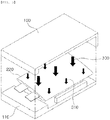
- FIG. 1 is a schematic view showing an all-solid-state battery 200 having a surface that is not smooth and pressures 300 and 310 that are applied from a jig 100 and 110 to the all-solid-state battery 200 at the time of a conventional activation process. It can be seen that higher pressure is applied to the protruding portion of the surface than to the recessed portion of the surface.
- pressures 300, 310, and 320 are indicated by arrows having different sizes. In the case in which the size of the arrow is larger, pressure is higher. In the case in which the size of the arrow is smaller, pressure is lower. In the case in which the sizes of the arrows are equal to each other, pressure is uniform.
- fluid layers 400 and 410 uniformly wrap a battery, whereby uniform pressure is applied to the battery.
- FIG. 2 is a schematic view showing an all-solid-state battery 210 configured such that a portion of the surface thereof protrudes and pressures 300 and 310 that are applied from the jig 100 and 110 to the all-solid-state battery 210 at the time of the conventional activation process.
- the all-solid-state battery 210 having the protrusion higher pressure is applied to the protruding portion of the battery than the planar portion of the battery.
- fluid layers 400 and 410 uniformly wrap a battery, whereby uniform pressure is applied to the battery.
- FIG. 3 is a schematic view showing an oval all-solid-state battery 220 and pressures 300 and 310 that are applied from the jig 100 and 110 to the all-solid-state battery 220 at the time of the conventional activation process.
- the middle portion of the battery protrudes. Even in the case of the oval all-solid-state battery 220, therefore, pressure is applied to the middle portion of the battery.
- fluid layers 400 and 410 uniformly wrap a battery, whereby uniform pressure is applied to the battery.
- pouch-shaped battery cells configured such that a planar portion of each of the battery cells to which no separate shape or roughness was added was a round quadrangular circle and having uniform heights were used.
- charging was performed under conditions of (CC/CV): 0.05C/4.15V, 0.02C cut-off, and rest 30 min, and discharging was performed under conditions of (CC): 0.05C and 3V cut off.
- a pressure of 500 kgf/cm 2 was applied to a jig.
- the jig was configured so as to have a shape wrapping all surfaces of the battery.
- a fluid pouch was configured so as to wrap all of the surfaces of the battery cell.
- the fluid pouch was configured to have a shape with a predetermined thickness.
- a fluid pouch having a thickness of 75 ⁇ m was used.
- Example 1 a fluid pouch containing gas in the atmosphere was disposed between the battery cell and the jig.
- Example 2 a fluid pouch containing water was disposed between the battery cell and the jig.
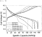
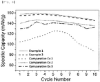
- the examples of the present invention and the comparative examples had the capacities in the same sequence as one-time charging and discharging even when the batteries were charged and discharged ten times.
- the present invention relates to a method of uniformly applying pressure between a battery cell and a jig to a battery at the time of activating the battery, and has advantages in that uniform pressure is applied to the battery at the time of activation and the initial performance of the battery is improved, whereby the lifespan of the battery is longer than the lifespan of a conventional battery.
Landscapes
- Chemical & Material Sciences (AREA)
- Electrochemistry (AREA)
- Engineering & Computer Science (AREA)
- Manufacturing & Machinery (AREA)
- Chemical Kinetics & Catalysis (AREA)
- General Chemical & Material Sciences (AREA)
- Condensed Matter Physics & Semiconductors (AREA)
- General Physics & Mathematics (AREA)
- Inorganic Chemistry (AREA)
- Physics & Mathematics (AREA)
- Dispersion Chemistry (AREA)
- Secondary Cells (AREA)
- Sealing Battery Cases Or Jackets (AREA)
Applications Claiming Priority (2)
| Application Number | Priority Date | Filing Date | Title |
|---|---|---|---|
| KR1020190053691A KR102754480B1 (ko) | 2019-05-08 | 2019-05-08 | 전고체전지의 제조방법 및 이를 이용하여 제조되는 전고체전지 |
| PCT/KR2020/005223 WO2020226299A1 (fr) | 2019-05-08 | 2020-04-20 | Procédé de fabrication d'une batterie entièrement solide, et batterie entièrement solide fabriquée à l'aide de celui-ci |
Publications (2)
| Publication Number | Publication Date |
|---|---|
| EP3907806A1 true EP3907806A1 (fr) | 2021-11-10 |
| EP3907806A4 EP3907806A4 (fr) | 2022-03-16 |
Family
ID=73051106
Family Applications (1)
| Application Number | Title | Priority Date | Filing Date |
|---|---|---|---|
| EP20802870.4A Pending EP3907806A4 (fr) | 2019-05-08 | 2020-04-20 | Procédé de fabrication d'une batterie entièrement solide, et batterie entièrement solide fabriquée à l'aide de celui-ci |
Country Status (6)
| Country | Link |
|---|---|
| US (2) | US12394779B2 (fr) |
| EP (1) | EP3907806A4 (fr) |
| JP (1) | JP7262721B2 (fr) |
| KR (1) | KR102754480B1 (fr) |
| CN (1) | CN113748554A (fr) |
| WO (1) | WO2020226299A1 (fr) |
Families Citing this family (24)
| Publication number | Priority date | Publication date | Assignee | Title |
|---|---|---|---|---|
| KR20220083025A (ko) | 2020-12-11 | 2022-06-20 | 주식회사 엘지에너지솔루션 | 전지 셀의 충방전 장치 및 이를 이용한 전지 셀의 충방전 방법 |
| KR20220128087A (ko) * | 2021-03-12 | 2022-09-20 | 한국기초과학지원연구원 | 파우치형 전고체 리튬이차전지 및 이의 제조 방법 |
| KR102800121B1 (ko) * | 2021-04-09 | 2025-04-28 | 주식회사 엘지에너지솔루션 | 전고체전지 제조방법 및 이에 의한 전고체전지 |
| JP7531976B2 (ja) * | 2021-04-09 | 2024-08-13 | エルジー エナジー ソリューション リミテッド | 全固体電池の製造方法及びこれによる全固体電池 |
| US11631890B2 (en) * | 2021-05-06 | 2023-04-18 | Solid Energies Inc. | All solid-state lithium-ion battery produced by pressure-aided co-curing |
| KR102570543B1 (ko) | 2021-05-26 | 2023-08-28 | (주)나노제네시스 | 그래핀-금속 입자 복합체를 포함하는 전고체전지용 음극 및 이를 포함하는 전고체전지 |
| KR102581082B1 (ko) * | 2021-11-26 | 2023-09-21 | (주)하나기술 | 전고체용 이차전지 가압시스템 |
| KR102918430B1 (ko) * | 2021-12-06 | 2026-01-26 | 주식회사 엘지에너지솔루션 | 이차전지 생산을 위한 vr 기반의 화재 대응 시뮬레이션 방법 및 장치 |
| KR102769631B1 (ko) * | 2022-07-21 | 2025-02-19 | (주)하나기술 | 전고체용 이차전지 가압시스템 및 그 방법 |
| KR102449415B1 (ko) | 2022-02-04 | 2022-10-11 | (주)바이오제네시스 | 하이브리드 그래핀을 포함하는 리튬이온전지용 음극 |
| KR102545572B1 (ko) | 2022-09-27 | 2023-06-29 | (주)바이오제네시스 | 하이브리드 그래핀 양극이 포함된 배터리 |
| KR102545573B1 (ko) | 2022-09-27 | 2023-06-21 | (주)바이오제네시스 | 하이브리드 그래핀 복합 입자 |
| KR102867411B1 (ko) * | 2022-11-09 | 2025-09-30 | 삼성에스디아이 주식회사 | 전고체전지 및 그 제조방법 |
| KR20240113249A (ko) * | 2023-01-13 | 2024-07-22 | 주식회사 엘지에너지솔루션 | 실험용 지그 |
| KR102928742B1 (ko) | 2023-03-08 | 2026-02-23 | (주)나노제네시스 | 탄소 코팅된 미세입자 제조방법 |
| KR102925291B1 (ko) * | 2023-04-06 | 2026-02-06 | 삼성에스디아이 주식회사 | 전고체전지 모듈 및 그 제조 방법 |
| KR102894438B1 (ko) * | 2023-04-06 | 2025-12-01 | 삼성에스디아이 주식회사 | 전고체 전지 제조방법 및 그 방법에 사용되는 공정 플레이트 |
| KR20240175184A (ko) | 2023-06-12 | 2024-12-19 | (주)나노제네시스 | 미세입자가 돌출된 표면을 갖는 하이브리드 카본 복합입자 |
| KR20250074171A (ko) | 2023-11-20 | 2025-05-27 | 주식회사 엘지에너지솔루션 | 파우치형 전지셀 활성화 장치 및 이를 이용한 활성화방법 |
| EP4693545A1 (fr) * | 2023-11-28 | 2026-02-11 | LG Energy Solution, Ltd. | Procédé et dispositif de mise sous pression isostatique pour batterie entièrement solide, et module de cellule de batterie comprenant un dispositif de mise sous pression isostatique |
| KR20250096329A (ko) * | 2023-12-20 | 2025-06-27 | 주식회사 엘지에너지솔루션 | 전고체 전지의 활성화 방법 |
| KR20250100397A (ko) * | 2023-12-26 | 2025-07-03 | 삼성에스디아이 주식회사 | 전고체 이차 전지 및 이를 포함하는 전고체 이차 전지 팩 |
| KR20260042676A (ko) * | 2024-09-23 | 2026-03-31 | 주식회사 엘지에너지솔루션 | 파우치셀 등방가압용 지그 및 이를 사용하는 파우치셀의 등방가압 방법 |
| KR20260042681A (ko) * | 2024-09-23 | 2026-03-31 | 주식회사 엘지에너지솔루션 | 플렉서블한 파우치셀 등방가압용 지그 및 이를 사용하는 파우치셀의 등방가압 방법 |
Family Cites Families (35)
| Publication number | Priority date | Publication date | Assignee | Title |
|---|---|---|---|---|
| JP2561127Y2 (ja) * | 1991-11-29 | 1998-01-28 | 日本電池株式会社 | 蓄電池用スペ−サ |
| JPH10214638A (ja) | 1997-01-30 | 1998-08-11 | Hitachi Ltd | リチウム二次電池 |
| JP3457624B2 (ja) * | 2000-04-14 | 2003-10-20 | 日本電気株式会社 | 扁平型電池の製造方法 |
| US20070035070A1 (en) * | 2005-08-15 | 2007-02-15 | Essilor International Compagnie Generale D'optique | Inflatable membrane pressing apparatus for a film or coating application or lamination process |
| JP5266634B2 (ja) | 2006-12-08 | 2013-08-21 | 日産自動車株式会社 | 電力供給装置およびその制御方法 |
| JP2009295289A (ja) * | 2008-06-02 | 2009-12-17 | Panasonic Corp | リチウムイオン二次電池およびその製造方法 |
| ES2586606T3 (es) * | 2008-11-25 | 2016-10-17 | Hueck Rheinische Gmbh | Prensa de placas y unidad de chapa de prensa-cojín de prensa |
| JP2012519366A (ja) * | 2009-03-02 | 2012-08-23 | エルジー ケム. エルティーディ. | パウチおよびこれを含む二次電池 |
| JP2012129009A (ja) | 2010-12-14 | 2012-07-05 | Nissan Motor Co Ltd | 電池パック |
| JP5257471B2 (ja) | 2010-12-28 | 2013-08-07 | トヨタ自動車株式会社 | 電池 |
| JP2012169204A (ja) | 2011-02-16 | 2012-09-06 | Toyota Motor Corp | 電池構造体 |
| JP2012221773A (ja) | 2011-04-11 | 2012-11-12 | Toyota Motor Corp | 固体電池及び固体電池システム |
| US20140170468A1 (en) | 2011-07-13 | 2014-06-19 | Toyota Jidosha Kabushiki Kaisha | Battery module |
| JP5754337B2 (ja) | 2011-10-11 | 2015-07-29 | トヨタ自動車株式会社 | 蓄電装置 |
| US20190006699A1 (en) | 2013-01-16 | 2019-01-03 | Sion Power Corporation | Pressure and/or temperature management in electrochemical systems |
| KR20150050223A (ko) | 2013-10-31 | 2015-05-08 | 주식회사 엘지화학 | 가압 트레이 및 이에 적용되는 가압 지그 |
| CN204614858U (zh) * | 2013-10-31 | 2015-09-02 | 株式会社Lg化学 | 电极组件和包含其的锂二次电池 |
| KR20160001399A (ko) | 2014-06-27 | 2016-01-06 | 주식회사 엘지화학 | 이차전지 전극 조립체용 가압 트레이 |
| JP2016012495A (ja) * | 2014-06-30 | 2016-01-21 | トヨタ自動車株式会社 | リチウム固体二次電池およびその製造方法 |
| JP6103315B2 (ja) * | 2014-10-03 | 2017-03-29 | トヨタ自動車株式会社 | 非水系二次電池および該電池の製造方法 |
| JP6569883B2 (ja) * | 2016-04-15 | 2019-09-04 | 株式会社豊田自動織機 | 電解液及びリチウムイオン二次電池 |
| KR102282481B1 (ko) | 2016-09-01 | 2021-07-27 | 주식회사 엘지에너지솔루션 | 가압 지그 및 이를 이용한 이차전지 제조 방법 |
| KR102256599B1 (ko) * | 2016-09-01 | 2021-05-26 | 주식회사 엘지에너지솔루션 | 가압 지그 및 이를 이용한 이차전지 제조 방법 |
| EP3518322A4 (fr) | 2016-09-23 | 2019-08-07 | Nissan Motor Co., Ltd. | Procédé de production de batterie de type film-gaine |
| JP2018106984A (ja) | 2016-12-27 | 2018-07-05 | トヨタ自動車株式会社 | 全固体リチウムイオン電池 |
| CN207282663U (zh) | 2017-07-11 | 2018-04-27 | 佛山市金广源电源科技有限公司 | 一种全固态电池的充电系统 |
| KR102447619B1 (ko) | 2017-09-18 | 2022-09-27 | 주식회사 엘지에너지솔루션 | 지그를 이용한 고정 과정을 포함하는 파우치형 전지셀 제조방법 |
| JP6926972B2 (ja) * | 2017-11-10 | 2021-08-25 | トヨタ自動車株式会社 | 全固体電池の製造方法 |
| KR20190053691A (ko) | 2017-11-10 | 2019-05-20 | 엘지디스플레이 주식회사 | 표시 장치 |
| CN208433485U (zh) * | 2018-06-29 | 2019-01-25 | 深圳市深远大科技有限公司 | 一种电池压力化成装置 |
| JP7026252B2 (ja) * | 2018-09-27 | 2022-02-25 | 株式会社村田製作所 | リチウムイオン二次電池用電解液およびリチウムイオン二次電池 |
| CN109980234A (zh) * | 2019-03-29 | 2019-07-05 | 宁德新能源科技有限公司 | 复合集流体与包含其的复合极片及电化学装置 |
| DE102019005916A1 (de) * | 2019-08-22 | 2021-02-25 | Siempelkamp Maschinen- Und Anlagenbau Gmbh | Verfahren zum Vorspannen der Membran einer Membranpresse und Presse zur Durchführung dieses Verfahrens |
| HUE071136T2 (hu) * | 2020-03-27 | 2025-08-28 | Samsung Sdi Co Ltd | Fluidumrugóval nyomás alá helyezett akkumulátorköteg |
| WO2024238432A1 (fr) * | 2023-05-15 | 2024-11-21 | Factorial Inc. | Ensemble de cellules densifiées et son procédé de préparation |
-
2019
- 2019-05-08 KR KR1020190053691A patent/KR102754480B1/ko active Active
-
2020
- 2020-04-20 US US17/424,777 patent/US12394779B2/en active Active
- 2020-04-20 JP JP2021545771A patent/JP7262721B2/ja active Active
- 2020-04-20 CN CN202080031316.0A patent/CN113748554A/zh active Pending
- 2020-04-20 EP EP20802870.4A patent/EP3907806A4/fr active Pending
- 2020-04-20 WO PCT/KR2020/005223 patent/WO2020226299A1/fr not_active Ceased
-
2025
- 2025-07-09 US US19/263,718 patent/US20250336912A1/en active Pending
Also Published As
| Publication number | Publication date |
|---|---|
| KR102754480B1 (ko) | 2025-01-17 |
| CN113748554A (zh) | 2021-12-03 |
| US12394779B2 (en) | 2025-08-19 |
| US20220069277A1 (en) | 2022-03-03 |
| JP2022520345A (ja) | 2022-03-30 |
| EP3907806A4 (fr) | 2022-03-16 |
| US20250336912A1 (en) | 2025-10-30 |
| JP7262721B2 (ja) | 2023-04-24 |
| KR20200129379A (ko) | 2020-11-18 |
| WO2020226299A1 (fr) | 2020-11-12 |
Similar Documents
| Publication | Publication Date | Title |
|---|---|---|
| US20250336912A1 (en) | Method of Manufacturing All-Solid-State Battery and All-Solid-State Battery Manufactured Using the Same | |
| US11876185B2 (en) | Method for manufacturing secondary battery and secondary battery | |
| KR102334022B1 (ko) | 전해액 보충용 홈이 형성된 파우치형 이차전지 | |
| EP3076468B1 (fr) | Élément de batterie utilisant des particules inertes pour une meilleure sécurité de la batterie | |
| KR102872034B1 (ko) | 가압 패드를 포함하는 전지 셀의 가압 지그 및 이를 이용한 전지 셀의 디가싱 방법 | |
| US20240322278A1 (en) | Secondary battery including pouch with gas adsorbent interposed therein and method for manufacturing same | |
| CN117693844A (zh) | 二次电池制造设备和二次电池制造方法 | |
| CN114730926B (zh) | 配置为能够补充电解质溶液的袋形电池单元 | |
| KR20260002472A (ko) | 배터리 모듈, 이를 포함하는 배터리 팩 및 자동차 | |
| US10050301B2 (en) | Battery cell including electrode assembly coated with inert particles | |
| JP2024108539A (ja) | 組電池 | |
| KR20230008616A (ko) | 파우치형 이차전지의 디게싱 방법 | |
| KR102537516B1 (ko) | 이차전지 제조방법 및 이차전지 디개스 장치 | |
| US9601730B2 (en) | Secondary battery frame and battery pack including the same | |
| KR101675988B1 (ko) | 불활성 입자를 함유하는 전극을 포함하는 전지셀 | |
| KR101675985B1 (ko) | 불활성 입자가 코팅되어 있는 전극을 포함하는 전지셀 | |
| KR20230030811A (ko) | 이중 케이스를 포함하는 파우치형 전지셀 및 이의 제조방법 | |
| KR20220018800A (ko) | 히트싱크에 배터리 셀을 접착하는 방법 및 이를 이용하여 제조된 배터리 모듈 |
Legal Events
| Date | Code | Title | Description |
|---|---|---|---|
| STAA | Information on the status of an ep patent application or granted ep patent |
Free format text: STATUS: THE INTERNATIONAL PUBLICATION HAS BEEN MADE |
|
| PUAI | Public reference made under article 153(3) epc to a published international application that has entered the european phase |
Free format text: ORIGINAL CODE: 0009012 |
|
| STAA | Information on the status of an ep patent application or granted ep patent |
Free format text: STATUS: REQUEST FOR EXAMINATION WAS MADE |
|
| 17P | Request for examination filed |
Effective date: 20210805 |
|
| AK | Designated contracting states |
Kind code of ref document: A1 Designated state(s): AL AT BE BG CH CY CZ DE DK EE ES FI FR GB GR HR HU IE IS IT LI LT LU LV MC MK MT NL NO PL PT RO RS SE SI SK SM TR |
|
| A4 | Supplementary search report drawn up and despatched |
Effective date: 20220210 |
|
| RIC1 | Information provided on ipc code assigned before grant |
Ipc: H01M 10/04 20060101ALI20220204BHEP Ipc: H01M 4/04 20060101ALI20220204BHEP Ipc: H01M 10/44 20060101ALI20220204BHEP Ipc: H01M 10/0562 20100101ALI20220204BHEP Ipc: H01M 10/0585 20100101ALI20220204BHEP Ipc: H01M 10/058 20100101AFI20220204BHEP |
|
| RAP3 | Party data changed (applicant data changed or rights of an application transferred) |
Owner name: LG ENERGY SOLUTION, LTD. |
|
| DAV | Request for validation of the european patent (deleted) | ||
| DAX | Request for extension of the european patent (deleted) |