EP3908077B1 - Induktionserwärmungsvorrichtung und verfahren zur steuerung davon - Google Patents
Induktionserwärmungsvorrichtung und verfahren zur steuerung davon Download PDFInfo
- Publication number
- EP3908077B1 EP3908077B1 EP21172567.6A EP21172567A EP3908077B1 EP 3908077 B1 EP3908077 B1 EP 3908077B1 EP 21172567 A EP21172567 A EP 21172567A EP 3908077 B1 EP3908077 B1 EP 3908077B1
- Authority
- EP
- European Patent Office
- Prior art keywords
- working coil
- power value
- required power
- mode
- inverter circuit
- Prior art date
- Legal status (The legal status is an assumption and is not a legal conclusion. Google has not performed a legal analysis and makes no representation as to the accuracy of the status listed.)
- Active
Links
Images





Classifications
-
- H—ELECTRICITY
- H05—ELECTRIC TECHNIQUES NOT OTHERWISE PROVIDED FOR
- H05B—ELECTRIC HEATING; ELECTRIC LIGHT SOURCES NOT OTHERWISE PROVIDED FOR; CIRCUIT ARRANGEMENTS FOR ELECTRIC LIGHT SOURCES, IN GENERAL
- H05B6/00—Heating by electric, magnetic or electromagnetic fields
- H05B6/02—Induction heating
- H05B6/06—Control, e.g. of temperature, of power
- H05B6/062—Control, e.g. of temperature, of power for cooking plates or the like
- H05B6/065—Control, e.g. of temperature, of power for cooking plates or the like using coordinated control of multiple induction coils
-
- H—ELECTRICITY
- H05—ELECTRIC TECHNIQUES NOT OTHERWISE PROVIDED FOR
- H05B—ELECTRIC HEATING; ELECTRIC LIGHT SOURCES NOT OTHERWISE PROVIDED FOR; CIRCUIT ARRANGEMENTS FOR ELECTRIC LIGHT SOURCES, IN GENERAL
- H05B6/00—Heating by electric, magnetic or electromagnetic fields
- H05B6/02—Induction heating
- H05B6/06—Control, e.g. of temperature, of power
- H05B6/062—Control, e.g. of temperature, of power for cooking plates or the like
-
- H—ELECTRICITY
- H02—GENERATION; CONVERSION OR DISTRIBUTION OF ELECTRIC POWER
- H02M—APPARATUS FOR CONVERSION BETWEEN AC AND AC, BETWEEN AC AND DC, OR BETWEEN DC AND DC, AND FOR USE WITH MAINS OR SIMILAR POWER SUPPLY SYSTEMS; CONVERSION OF DC OR AC INPUT POWER INTO SURGE OUTPUT POWER; CONTROL OR REGULATION THEREOF
- H02M7/00—Conversion of AC power input into DC power output; Conversion of DC power input into AC power output
- H02M7/42—Conversion of DC power input into AC power output without possibility of reversal
- H02M7/44—Conversion of DC power input into AC power output without possibility of reversal by static converters
- H02M7/48—Conversion of DC power input into AC power output without possibility of reversal by static converters using discharge tubes with control electrode or semiconductor devices with control electrode
- H02M7/53—Conversion of DC power input into AC power output without possibility of reversal by static converters using discharge tubes with control electrode or semiconductor devices with control electrode using devices of a triode or transistor type requiring continuous application of a control signal
- H02M7/537—Conversion of DC power input into AC power output without possibility of reversal by static converters using discharge tubes with control electrode or semiconductor devices with control electrode using devices of a triode or transistor type requiring continuous application of a control signal using semiconductor devices only, e.g. single switched pulse inverters
-
- H—ELECTRICITY
- H02—GENERATION; CONVERSION OR DISTRIBUTION OF ELECTRIC POWER
- H02M—APPARATUS FOR CONVERSION BETWEEN AC AND AC, BETWEEN AC AND DC, OR BETWEEN DC AND DC, AND FOR USE WITH MAINS OR SIMILAR POWER SUPPLY SYSTEMS; CONVERSION OF DC OR AC INPUT POWER INTO SURGE OUTPUT POWER; CONTROL OR REGULATION THEREOF
- H02M7/00—Conversion of AC power input into DC power output; Conversion of DC power input into AC power output
- H02M7/42—Conversion of DC power input into AC power output without possibility of reversal
- H02M7/44—Conversion of DC power input into AC power output without possibility of reversal by static converters
- H02M7/48—Conversion of DC power input into AC power output without possibility of reversal by static converters using discharge tubes with control electrode or semiconductor devices with control electrode
- H02M7/53—Conversion of DC power input into AC power output without possibility of reversal by static converters using discharge tubes with control electrode or semiconductor devices with control electrode using devices of a triode or transistor type requiring continuous application of a control signal
- H02M7/537—Conversion of DC power input into AC power output without possibility of reversal by static converters using discharge tubes with control electrode or semiconductor devices with control electrode using devices of a triode or transistor type requiring continuous application of a control signal using semiconductor devices only, e.g. single switched pulse inverters
- H02M7/5387—Conversion of DC power input into AC power output without possibility of reversal by static converters using discharge tubes with control electrode or semiconductor devices with control electrode using devices of a triode or transistor type requiring continuous application of a control signal using semiconductor devices only, e.g. single switched pulse inverters in a bridge configuration
-
- H—ELECTRICITY
- H05—ELECTRIC TECHNIQUES NOT OTHERWISE PROVIDED FOR
- H05B—ELECTRIC HEATING; ELECTRIC LIGHT SOURCES NOT OTHERWISE PROVIDED FOR; CIRCUIT ARRANGEMENTS FOR ELECTRIC LIGHT SOURCES, IN GENERAL
- H05B1/00—Details of electric heating devices
- H05B1/02—Automatic switching arrangements specially adapted to apparatus ; Control of heating devices
-
- H—ELECTRICITY
- H05—ELECTRIC TECHNIQUES NOT OTHERWISE PROVIDED FOR
- H05B—ELECTRIC HEATING; ELECTRIC LIGHT SOURCES NOT OTHERWISE PROVIDED FOR; CIRCUIT ARRANGEMENTS FOR ELECTRIC LIGHT SOURCES, IN GENERAL
- H05B6/00—Heating by electric, magnetic or electromagnetic fields
- H05B6/02—Induction heating
- H05B6/04—Sources of current
Definitions
- an induction heating apparatus Disclosed herein are an induction heating apparatus and a method of controlling the same.
- Induction heating apparatuses are devices that generate eddy current in a metallic container and heat the container using a magnetic field generated around a working coil.
- an induction heating apparatus When an induction heating apparatus is driven, high-frequency current is supplied to the working coil. Then, an induction magnetic field is generated around the working coil disposed in the induction heating apparatus.
- magnetic line of force of the induction magnetic field passes through a bottom of the metallic container over the working coil, eddy current is generated inside the bottom of the container. Accordingly, the eddy current flows in the container, and the container itself is heated.
- the induction heating apparatus includes two or more heating zones and two or more working coils corresponding to the two or more heating zones. For example, when a user places containers respectively in two heating zones and inputs heating initiation instructions, each of the working coils is driven at a driving frequency corresponding to a required power value set by the user.
- FIG. 1 is a graph showing curves of resonance characteristics of two working coils respectively when an induction heating apparatus including the two working coils is driven.
- FIG. 1 shows a curve of a resonance characteristic of each of the working coils i.e., a curve 31 of a resonance characteristic of a first working coil and a curve 32 of a resonance characteristic of a second working coil, when the two working coils are respectively driven in a state in which a container is placed in each of the heating zones of the induction heating apparatus.
- a resonance frequency of the first working coil is fr1
- a resonance frequency of the second working coil is fr2.
- a first required power value of the first working coil is P1
- a required power value of the second working coil is P2. Accordingly, the first working coil is driven at a first driving frequency f1 corresponding to the first required power value P1, and the second working coil is driven at a second driving frequency f2 corresponding to the second required power value P2.
- interference noise is generated due to the driving of the working coils when a difference value (f2-f1) between the driving frequencies of the working coils is included in an audible frequency band (e.g., 2 kHz to 20 kHz).
- the interference noise may cause inconvenience to a user and cause a user to wonder if the induction heating apparatus is out of order.
- a driving frequency of at least one of the two working coils is randomly adjusted such that the difference value (f2-f1) between the driving frequencies of the working coils is out of the audible frequency band.
- the driving frequency of the working coil is randomly adjusted to reduce the interference noise, an output power value of the working coil does not match a required power value set by a user.
- JP 2012 226900 A presents an induction heating cooker that comprises a plurality of heating coils energized independently from one another, drive circuits provided correspondingly to the plurality of heating coils respectively, input power detection circuits for detecting input powers to the drive circuits respectively, and a control circuit for controlling drive frequencies of the drive circuits such that input powers to the drive circuits become target input powers that are input powers corresponding to a heating power set at an operation part.
- the control circuit has an interference sound inhibition mode in which the drive circuits are controlled such that paired two drive circuits in a drive state can continue a sweep state in which a difference between drive frequencies of the paired drive circuits continuously varies.
- WO 2019/074246 A1 relates to an induction heating apparatus.
- the technique compares a resistance value of a container with a predetermined reference resistance value, and determines an operating mode of a switching device according to a result of the comparison. It is possible to use various types of containers without increasing an operating frequency of an induction heating apparatus, by adjusting a resonance frequency of a working coil according to a resistance value of a container used in the induction heating apparatus.
- EP 3 618 568 A1 presents an induction heating device and method for controlling induction heating device.
- the method includes determining a first target frequency of a first working coil corresponding to the drive command for the first working coil, determining a second target frequency of the second working coil corresponding to the drive command for the second working coil, and determining a final drive frequency of the first working coil and a final drive frequency of the second working coil based on the first target frequency and the second target frequency, respectively.
- JP 2011 150799 A presents an induction heating apparatus.
- the inverter with a lower frequency executes frequency control that maintains a conduction ratio to be 50%, and meanwhile, the inverter with a higher frequency is set to have a limit of the frequency to reduce semiconductor switch loss and prevent the interference sound.
- EP 3 133 899 A1 relates to an induction-heating cooker which inductively heats a single heated body by means of a plurality of induction-heating coils of the induction-heating cooker, and a method of controlling thereof.
- JP 2007 080751 A relates to a power control method for heating a metal pan (load) that is a non-heating metal body of an induction heating cooker.
- An object of the present invention is to provide an induction heating apparatus and a method for controlling the same that may prevent interference noise caused by driving of two working coils while maintaining output power values and required power values of the working coils at the same value when the working coils are driven at the same time.
- An object of the present invention is to provide an induction heating apparatus and a method for controlling the same that may prevent interference noise caused by driving of working coils when various types of containers having different properties are heated.
- An induction heating apparatus may include a first working coil and a second working coil.
- the first working coil may be driven at a first driving frequency corresponding to a first required power value set by a user
- the second working coil may be driven at a second driving frequency corresponding to a second required power value set by the user.
- the driving frequency of the second working coil needs to be changed to the third driving frequency.
- an output power value may decrease in an entire frequency band of the first working coil or the second working coil. Accordingly, the difference value between the driving frequency of the first working coil and the driving frequency of the second working coil may be greater than a boundary value (e.g., 20 kHz) of the audible frequency band. As a result of control above, the interference noise caused by the driving of the working coils may be prevented.
- the output power value of the first working coil or the second working coil may be adjusted without changing the diving frequency of the first working coil or the second working coil.
- the output power value of the first working coil or the second working coil is adjusted to the third required power value, the interference noise caused by the driving of the working coils may be prevented.
- An induction heating apparatus may include a first working coil, a first inverter circuit driven at a first driving frequency corresponding to a first required power value of the first working coil and configured to supply the first working coil with current, a second working coil, a second inverter circuit driven at a second driving frequency corresponding to a second required power value of the second working coil and configured to supply the second working coil with current.
- a controller is configured to determine a third driving frequency corresponding to a third required power value when the required power value of the first working coil or the second working coil is changed to the third required power value.
- the controller is further configured to calculate a difference value between the driving frequency of the working coil, which is not changed in its required power value and the third driving frequency for the working coil which is changed it is required power value.
- the controller is further configured to change an operation mode or a power control mode of the first inverter circuit or the second inverter circuit when the difference value is included in a predetermined first reference range.
- the difference between the two driving frequencies is evaluated whether it causes interference noise.
- the controllers may change the operation mode of the first inverter circuit to a half bridge mode and change a driving frequency of the first inverter circuit to a fourth driving frequency corresponding to the third required power value.
- the first inverter circuit may include a variable capacitor part, and a relay part connected to the variable capacitor part, wherein the controller sets a capacitance value of the variable capacitor part to Cr,h of an equation below (equation 1) by opening or closing a plurality of relays included in the relay part.
- C r . h 1 2 ⁇ f r . h 2 L r (Herein, fr,h may be the same value as a frequency of a switching signal input to the second inverter circuit, and Lr may be an inductance value of a second inductor included in the second inverter circuit.)
- the controller may change the power control mode of the first inverter circuit to an asymmetric pulse width modulation mode.
- one of the criteria to be checked is the resonance frequency of the first and second working coil.
- the controller may change a power control mode of the working coil, the required power value is changed, to any one of the asymmetric pulse width modulation mode and a phase shift mode, and may adjust the output power value of the working coil, the required power value of which is changed, to the third required power value based on the power control mode.
- FIG. 2 shows two working coil assemblies, i.e., a first working coil assembly 122 and a second working coil assembly 124 arranged in the case 102 as an example. However, three or more working coil assemblies may be disposed in the case 102 depending on embodiments.
- the relay part 206 may include a plurality of relays connected in series with each of the variable capacitors C2, C3, C4. Each relay included in the relay part 206 may be opened or closed by a control signal of the controller 2.
- an entire capacitance value of the variable capacitor C2, C3, C4 may vary. That is, the controller 2 may adjust a capacitance value of the variable capacitor C2, C3, C4 by opening or closing the relays included in the relay part 206.
- the controller 2 may determine an operation mode of the first inverter circuit 202, and may open/close state of each of the relays included in the relay part 206 such that the capacitance value of the variable capacitor C2, C3, C4 corresponds to the operation mode of the first inverter circuit 202. As described below, a frequency of resonance current following in the working coil 132 may be adjusted based on the capacitance value of the variable capacitor C2, C3, C4.
- variable capacitor part may include three capacitors C2, C3, C4 connected in parallel.
- the number of the capacitors included in the variable capacitor part may vary depending on embodiments.
- a connection (in series or in parallel) of the capacitor included in the variable capacitor part may differ depending on embodiments.
- the second rectifier circuit 212 may include a plurality of diode elements D5, D6, D7, D8.
- the second rectifier circuit 212 as illustrated in FIG. 3 , may be a bridge diode circuit, and may be a different circuit depending on embodiments.
- the second rectifier circuit 212 may rectify AC input voltage supplied from a power supply device 20 to output voltage having a pulse waveform.
- the second smoothing circuit L3, C5 may smooth the voltage rectified by the second rectifier circuit 212 and output DC link voltage.
- the second smoothing circuit L3, C5 may include a third inductor L3 and a second DC link capacitor C5.
- the second inverter circuit 214 may include a sixth capacitor C6, a seventh capacitor C7, a fifth switching element SW5, and a sixth switching element SW6. As illustrated in FIG. 3 , the second inverter circuit 214 of the induction heating apparatus 10 according to one embodiment may be implemented as a full bridge circuit including the two switching elements SW5, SW6.
- the fifth switching element SW5 and the sixth switching element SW6 may be complementarily turned on and turned off by a fifth switching signal S5 and a sixth switching signal S6 respectively output from the second driving circuit 24.
- FIG. 3 shows an IGBT element as each of the switching elements SW1, SW2, SW3, SW4, SW5, SW6.
- each of the switching elements SW1, SW2, SW3, SW4, SW5, SW6 may be a different type of switching element (e.g., a BJT or FET element and the like) depending on embodiments.
- DC link voltage input to the second inverter circuit 214 may be converted into AC voltage (AC current).
- the AC voltage (AC current) converted by the second inverter circuit 214 may be supplied to the second working coil 142.
- resonance may occur in the second working coil 142 and thermal energy may be supplied to a container.
- each of the fifth switching signal S5 and the sixth switching signal S6 may be a PWM signal having a predetermined duty ratio.
- each of the working coils 132, 142 When AC current output from each of the inverter circuits 204, 214 is supplied to each of the working coils 132, 142, each of the working coils 132, 142 may be driven. As a result of driving of each of the working coils 132, 142, eddy current may flow in the container placed over each of the working coil 132, 142 and the container may be heated. Magnitude of thermal energy supplied to the container may differ depending on magnitude of power that is actually generated as a result of driving of each of the working coils 132, 142, i.e., depending on an output power value of each of the working coils 132, 142.
- the controller 2 may determine a driving frequency of each of the working coils 132, 142 such that the driving frequency corresponds to a power level of a heating zone set by the user.
- the controller 2 may determine a driving frequency of each of the working coils 132, 142 with reference to a table in which a driving frequency corresponding to each power level is listed or with reference to an equation of a relationship between each power level and a driving frequency.
- magnitude of power, i.e., a required power value, output by each of the working coils 132, 142 may be determined based on the power level set by the user.
- the controller 2 may supply each of the driving circuits 22, 44 with a control signal corresponding to the determined driving frequency.
- Each of the driving circuits 22, 44 may output switching signals S1, S2, S3, S4, S5, S6 having a duty ratio corresponding to the driving frequency determined by the controller 2, based on the control signal output from the controller 2.
- the induction heating apparatus 10 When the induction heating apparatus 10 is powered on as a result of the user's manipulation of the interface of the induction heating apparatus 10, the induction heating apparatus 10 may get into a driving standby state as power is supplied to the induction heating apparatus from the power supply device 20. Then the user may place a container over each of the working coils 132, 142 of the induction heating apparatus 10 and set a power level for the container to input an instruction for initiating a heating process to each of the working coils 132, 142. When the user inputs the heating initiation instruction, a power value required by each of the working coils 132, 142, i.e., a required power value may be determined depending on the power level set by the user.
- the controller 2 may determine a driving frequency corresponding to the required power value of each of the working coils 132, 142, and may supply a control signal corresponding to the determined driving frequency to each of the driving circuits 22, 24. Accordingly, each of the driving circuits 22, 24 may output switching signals S1, S2, S3, S4, S5, S6, and each of the working coils 132, 142 may be driven as the switching signals S1, S2, S3, S4, S5, S6 are respectively input to the switching elements SW1, SW2, SW3, SW4, SW5, SW6. As a result of driving of each of the working coils 132, 142, eddy current may flow in the container, and the container may be heated.
- the required power value of the first working coil 132 or the second working coil 142 may be changed to a third required power value by the user.
- the controller 2 needs to change the driving frequency of the first working coil 132 to a third driving frequency corresponding to the third required power value (e.g., 500 W).
- interference noise may be generated depending on a difference value between the driving frequency of the working coil, whose driving frequency is not changed, and the third driving frequency.
- the controller 2 may determine the third driving frequency corresponding to the third required power value when the required power value of the first working coil 132 or the second working coil 142 is changed to the third required power value. To prevent the interference noise described above, the controller 2 may calculate a difference value between the driving frequency of the working coil the required power value of which is not changed, and the third driving frequency.
- a difference value between two driving frequencies denotes a value that is calculated as a result of deduction of a small value from a large value out of the two driving frequencies.
- the controller 2 may change an operation mode or a power control mode of the first inverter circuit 204 or the second inverter circuit 214 to prevent interference noise when the calculated difference value is included within a predetermined first reference range (e.g., a range from 5 kHz to 20 kHz).
- a predetermined first reference range e.g., a range from 5 kHz to 20 kHz.
- the controller 2 may change the operation mode of the first inverter circuit 204 from a full bridge mode to a half bridge mode, and may determine a fourth driving frequency of the first working coil 132 corresponding to the third required power value, to prevent interference noise.
- the controller 2 may change the driving frequency of the first inverter circuit 204 to the fourth frequency.
- an output power value of the first working coil 132 may decrease in an entire frequency band of the first working coil 132.
- the driving frequency i.e., the fourth driving frequency of the first working coil 132, corresponding to the third required power value
- a difference value between the driving frequency (the fourth driving frequency) of the first working coil 132 and the driving frequency (the second driving frequency) of the second working coil 142 may be a predetermined noise avoidance value (e.g., 22 kHz) or greater.
- the noise avoidance value may be set to a value greater than a maximum value (e.g., 20 kHz) among boundary values of an audible frequency band, and may be set differently depending on embodiments.
- the controller 2 may adjust a duty ratio of a switching signal for driving the working coil, the required power value of which is changed, to change the output power value of the working coil, the required power value of which is changed, to the third required power value, when the power control mode is set to the asymmetric pulse width modulation mode.
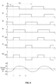
- the controller 2 may confirm whether the calculated difference value (18) is included in a predetermined first reference range (e.g., a range from 5 kHz to 20 kHz). Since the calculated difference value (18) is included in the first reference range, the controller 2 may change the operation mode of the first inverter circuit 204 to the half bridge mode. Accordingly, switching signals S1, S2, S3, S4 having waveforms illustrated in FIG. 9 may be respectively input to the first inverter circuit 204.
- a predetermined first reference range e.g., a range from 5 kHz to 20 kHz.
- the output power value of the first working coil 132 may decrease in an entire range of frequencies of the first working coil 132.
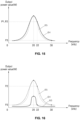
- the first working coil 132 may have a resonance characteristic that is new and the same as the resonance characteristic of the curve 63 illustrated in FIG. 14 .
- the controller 2 may determine a fourth driving frequency corresponding to the third required power value P3 after changing the operation mode of the first inverter circuit 204 to the half bridge mode. As illustrated in FIG. 14 , the fourth driving frequency corresponding to the third required power value P3 may be 15 kHz.
- a difference value (22) between the second driving frequency (37 kHz) of the second working coil 142 and the fourth driving frequency (15 kHz) of the first working coil 132 may be a predetermined noise avoidance value (e.g., 22) or greater and may be out of a second reference range.
- the controller 2 may drive the first working coil 132 at the fourth driving frequency (15 kHz) and drive the second working coil 142 at the second driving frequency (37 kHz).
- interference noise caused by the driving of the first working coil 132 and the second working coil 142 may be prevented although the output power value of the first working coil 132 is changed from P1 to P3.
- the controller 2 may change a power control mode of the first inverter circuit 204 to an asymmetric pulse width modulation mode. That is, the controller 2 may change a duty ratio of the switching signal input to the first inverter circuit 204 without changing the driving frequency of the first working coil 132 to change the output power value of the first working coil1 132.
- the user may decrease the power level of the first heating zone 12. As the power level of the first heating zone 12 decreases, the required power value of the first working coil 132 may decrease from P1 to P3.
- the controller 2 may determine a third driving frequency corresponding to a third required power value P3 that is a new required power value of the working coil, i.e., the first working coil 132 the required power value of which is changed. As illustrated in FIG. 15 , the third frequency corresponding to the third required power value P3 may be determined as 30 kHz.
- the controller 2 may calculate a difference value between the third driving frequency of the working coil the required power value of which is changed, and the driving frequency (the second driving frequency) of the working coil (the second working coil 142) the required power value of which is not changed.
- the difference value between the third driving frequency (22 kHz) and the second driving frequency (30 kHz) may be 8.
- the controller 2 may confirm whether the calculated difference value (8) is included in a predetermined first reference range (e.g., a range from 5 kHz to 20 kHz). Since the calculated difference value (8) is included in the first reference range and the operation mode of the first inverter circuit 204 is the full bridge mode, the controller 2 may change the power control mode of the first inverter circuit 204 to any one of the asymmetric pulse width modulation mode and the phase shift mode.
- a predetermined first reference range e.g., a range from 5 kHz to 20 kHz.
- the driving frequency of the first working coil 132 and the driving frequency of the second working coil 142 may be the same.
- interference noise caused by the driving of the first working coil 132 and the second working coil 142 may be prevented although the output power value of the first working coil 132 is changed from P1 to P3.
- a second required power value of the second working coil 142 corresponding to a power level of the second heating zone 14 set by the user, may be P2, and a driving frequency corresponding to the second required power value P2 may be 22 kHz.
- the controller 2 may set a second driving frequency of the second working coil 142 to 22 kHz and supply a control signal to the second driving circuit 24.
- the second working coil 142 may show the same resonance characteristic as that of the curve 65.
- the second working coil 142 may be driven at the driving frequency of 22 kHz, and an output power value of the second working coil 142 may be P2.
- a resonance frequency of the second working coil 142 may be 22 kHz. That is, in the embodiment of FIG. 15 , the resonance frequency of the first working coil 132 and the resonance frequency of the second working coil 142 may be the same.
- the controller 2 may determine a third driving frequency corresponding to a third required power value P3 that is a new required power value of the working coil, i.e., the second working coil 142 the required power value of which is changed. As illustrated in FIG. 18 , the third frequency corresponding to the third required power value P3 may be determined as 30 kHz.
- the controller 2 may adjust duty ratios of switching signals input to the second inverter circuit 214 to adjust the output power value of the second working coil 142 to P3 while maintaining the driving frequency of the second working coil 142 at the second driving frequency (22 kHz).
- the controller 2 may decrease the duty ratios of the switching signals input to the second inverter circuit 214 such that the second working coil 142 may have a resonance characteristic that is new and the same resonance characteristic as that of the curve 67 illustrated in FIG. 18 .
- the driving frequency of the second working coil 142 and the driving frequency of the first working coil 132 may be the same.
- interference noise caused by the driving of the first working coil 132 and the second working coil 142 may be prevented although the output power value of the second working coil 142 is changed from P2 to P3.
- the resonance frequency of the first working coil 132 and the resonance frequency of the second working coil 142 may be the same, and the first required power value P1 of the first working coil 132 and the second required power value P2 of the second working coil 142 may be the same.
- the method for controlling an induction heating apparatus according to the present disclosure may be applied even though the resonance frequency of the first working coil 132 and the resonance frequency of the second working coil 142 are different and the first required power value P1 of the first working coil 132 and the second required power value P2 of the second working coil 142 are different.
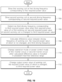
- FIG. 19 is a flow chart showing a method for controlling an induction heating apparatus according to one embodiment.
- a controller 2 of the induction heating apparatus 10 may drive a first working coil 132 at a first driving frequency corresponding to a first required power value set by a user (702). Additionally, the controller 2 may drive a second working coil 142 at a second driving frequency corresponding to a second required power value set by the user (704).
- the controller 2 may determine a third driving frequency corresponding to the third required power value (706).
- the controller 2 may calculate a difference value between the driving frequency of the working coil, the required power value of which is not change, and the third driving frequency (708).
- the controller 2 may change an operation mode or a power control mode of a first inverter circuit 204 or a second inverter circuit 214 when the calculated difference value is included in a predetermined first reference range (710).
- changing the operation mode or the power control mode of the first inverter circuit 204 or the second inverter circuit 214 (710) may include changing the operation mode of the first inverter circuit 204 to a half bridge mode and changing a driving frequency of the first inverter circuit 204 to a fourth driving frequency corresponding to the third required power value when a resonance frequency of the first working coil 132 is less than a resonance frequency of the second working coil 142 and the difference value between the driving frequency of the working coil, the required power value of which is not changed, and the third driving frequency is included in the predetermined first reference range.
- changing the operation mode or the power control mode of the first inverter circuit 204 or the second inverter circuit 214 (710) may include changing the power control mode of the working coil, the required power value of which is changed, to any one of an asymmetric pulse width modulation mode and a phase shift mode and adjusting an output power value of the working coil, the required power value of which is change, to the third required power value based on the changed power control mode, when the resonance frequency of the first working coil 132 and the resonance frequency of the second working coil 142 are the same and the difference value between the driving frequency of the working coil, the required power value of which is not changed, and the third driving frequency is included in the predetermined first reference range.
- changing the operation mode or the power control mode of the first inverter circuit 204 or the second inverter circuit 214 (710) may include changing the power control mode to the asymmetric pulse width modulation mode when the operation mode of the working coil the required power value of which is changed is the half bridge mode, and changing the power control mode to any one of the asymmetric pulse width modulation mode and the phase shift mode when then operation mode of the working coil the required power value of which is changed is a full bridge mode.
- the controller 2 may change the output power value of the working coil, the required power value of which is changed, to the third required power value (712).
- changing the output power value of the working coil, the required power value of which is changed, to the third required power value (712) may include adjusting a duty ratio of a switching signal for driving the working coil the required power value of which is changed, to change the output power value of the working coil the required power value of which is changed to the third required power value, when the power control mode is set to the asymmetric pulse width modulation mode.
- changing the output power value of the working coil, the required power value of which is changed, to the third required power value (712) may include adjusting a phase difference value between switching signals for driving the working coil the required power value of which is changed, to change the output power value of the working coil the required power value of which is changed to the third required power value, when the power control mode is set to the phase shift mode.
- the method for controlling an induction heating apparatus may further include changing the power control mode of the first inverter circuit 204 to the asymmetric pulse width modulation mode after the driving frequency of the first inverter circuit 204 is changed to the fourth driving frequency.
Landscapes
- Physics & Mathematics (AREA)
- Electromagnetism (AREA)
- Engineering & Computer Science (AREA)
- Power Engineering (AREA)
- General Induction Heating (AREA)
- Induction Heating Cooking Devices (AREA)
- Control Of High-Frequency Heating Circuits (AREA)
Claims (13)
- Induktionsheizvorrichtung, die Folgendes umfasst:eine erste Arbeitsspule (132);eine erste Wechselrichterschaltung (204), die mit einer ersten Ansteuerfrequenz entsprechend einem ersten erforderlichen Leistungswert der ersten Arbeitsspule (132) angesteuert wird und konfiguriert ist, die erste Arbeitsspule mit Strom zu versorgen;eine zweite Arbeitsspule (142);eine zweite Wechselrichterschaltung (214), die mit einer zweiten Ansteuerfrequenz entsprechend einem zweiten erforderlichen Leistungswert der zweiten Arbeitsspule (142) angesteuert wird und konfiguriert ist, die zweite Arbeitsspule mit Strom zu versorgen; undeine Steuereinheit (2), die konfiguriert ist zum:Ermitteln einer dritten Ansteuerfrequenz entsprechend einem dritten erforderlichen Leistungswert, wenn der erforderliche Leistungswert der ersten Arbeitsspule (132) oder der zweiten Arbeitsspule (142) auf den dritten erforderlichen Leistungswert geändert wird,Berechnen eines Differenzwerts zwischen der Ansteuerfrequenz der Arbeitsspule, deren erforderlicher Leistungswert nicht geändert wurde, und der dritten Ansteuerfrequenz, um eine Betriebsart oder eine Leistungssteuerungsbetriebsart der ersten Wechselrichterschaltung (204) oder der zweiten Wechselrichterschaltung (214) zu ändern, wenn der Differenzwert in einem zuvor festgelegten ersten Referenzbereich enthalten ist, undÄndern eines Ausgangsleistungswerts der Arbeitsspule, deren erforderlicher Leistungswert geändert wird, auf den dritten erforderlichen Leistungswert;wobei die erste Wechselrichterschaltung (204) eine Vollbrückenschaltung ist, unddadurch gekennzeichnet, dassdann, wenn eine Resonanzfrequenz der ersten Arbeitsspule (132) kleiner als eine Resonanzfrequenz der zweiten Arbeitsspule (142) ist und der Differenzwert im zuvor festgelegten ersten Referenzbereich enthalten ist, die Steuereinheit (2) konfiguriert ist, die Betriebsart der ersten Wechselrichterschaltung (204) in eine Halbbrücken-Betriebsart zu ändern und eine Ansteuerfrequenz der ersten Wechselrichterschaltung (204) entsprechend dem dritten erforderlichen Leistungswert auf eine vierte Ansteuerfrequenz zu ändern.
- Induktionsheizvorrichtung nach Anspruch 1, wobei die erste Wechselrichterschaltung (204) Folgendes umfasst:ein Element (C2, C3, C4) mit veränderlicher Kapazität; undein Relais-Element (206), das mit dem Element (C2, C3, C4) mit veränderlicher Kapazität verbunden ist,wobei die Steuereinheit (2) konfiguriert ist, einen Kapazitätswert des Elements (C2, C3, C4) mit veränderlicher Kapazität durch Öffnen oder Schließen mehrerer Relais, die im Relais-Element (206) enthalten sind, auf Cr,h der nachfolgenden Gleichung (Gleichung 1) einzustellen,
 wobei fr,h der gleiche Wert wie eine Frequenz eines Schaltsignals (S1-S4) ist, das bei der ersten Wechselrichterschaltung (204) eingegeben wird, und Lr ein Induktivitätswert eines zweiten Induktionselements (L2) ist, das in der ersten Wechselrichterschaltung (204) enthalten ist.
 - Induktionsheizvorrichtung nach Anspruch 1 oder 2, wobei dann, nachdem die Ansteuerfrequenz der ersten Wechselrichterschaltung (204) auf die vierte Ansteuerfrequenz geändert wurde, die Steuereinheit (2) konfiguriert ist, die Leistungssteuerungsbetriebsart der ersten Wechselrichterschaltung (204) in eine Betriebsart mit asymmetrischer Pulsbreitenmodulation zu ändern.
- Induktionsheizvorrichtung nach einem der vorhergehenden Ansprüche, wobei dann, wenn eine Resonanzfrequenz der ersten Arbeitsspule (132) die gleiche wie eine Resonanzfrequenz der zweiten Arbeitsspule (142) ist und der Differenzwert im zuvor festgelegten ersten Referenzbereich enthalten ist, die Steuereinheit (2) konfiguriert ist, eine Leistungssteuerungsbetriebsart der Arbeitsspule, deren erforderlicher Leistungswert geändert wird, in eine Betriebsart mit asymmetrischer Pulsbreitenmodulation oder in eine Phasenverschiebungsbetriebsart zu ändern, und den Ausgangsleistungswert der Arbeitsspule, deren erforderlicher Leistungswert geändert wird, auf den dritten erforderlichen Leistungswert auf der Basis der Leistungssteuerungsbetriebsart anzupassen.
- Induktionsheizvorrichtung nach Anspruch 4, wobei die Steuereinheit (2) konfiguriert ist, die Leistungssteuerungsbetriebsart in die Betriebsart mit asymmetrischer Pulsbreitenmodulation zu ändern, wenn die Betriebsart der Arbeitsspule, deren erforderlicher Leistungswert geändert wird, eine Halbbrücken-Betriebsart ist, und/oder
die Steuereinheit (2) konfiguriert ist, die Leistungssteuerungsbetriebsart in die Betriebsart mit asymmetrischer Pulsbreitenmodulation oder in die Phasenverschiebungsbetriebsart zu ändern, wenn die Betriebsart der Arbeitsspule, deren erforderlicher Leistungswert geändert wird, eine Vollbrücken-Betriebsart ist. - Induktionsheizvorrichtung nach einem der vorhergehenden Ansprüche, wobei dann, wenn die Leistungssteuerungsbetriebsart in eine Betriebsart mit asymmetrischer Pulsbreitenmodulation eingestellt wird, die Steuereinheit (2) konfiguriert ist, ein Lastverhältnis eines Schaltsignals (S1-S4) zum Ansteuern der Arbeitsspule, deren erforderlicher Leistungswert geändert wird, anzupassen, um den Ausgangsleistungswert der Arbeitsspule, deren erforderlicher Leistungswert geändert wird, auf den dritten erforderlichen Leistungswert zu ändern.
- Induktionsheizvorrichtung nach einem der vorhergehenden Ansprüche, wobei die Steuereinheit (2) dann, wenn die Leistungssteuerungsbetriebsart als eine Phasenverschiebungsbetriebsart eingestellt ist, konfiguriert ist, einen Phasendifferenzwert zwischen den Schaltsignalen zum Ansteuern der Arbeitsspule, deren erforderlicher Leistungswert geändert wird, anzupassen, um den Ausgangsleistungswert der Arbeitsspule, deren erforderlicher Leistungswert geändert wird, auf den dritten erforderlichen Leistungswert zu ändern.
- Verfahren zum Steuern einer Induktionsheizvorrichtung, das die folgenden Schritte umfasst:Ansteuern einer ersten Arbeitsspule (132) mit einer ersten Ansteuerfrequenz entsprechend einem ersten erforderlichen Leistungswert;Ansteuern einer zweiten Arbeitsspule (142) mit einer zweiten Ansteuerfrequenz entsprechend einem zweiten erforderlichen Leistungswert;Ermitteln einer dritten Ansteuerfrequenz entsprechend einem dritten erforderlichen Leistungswert, wenn der erforderliche Leistungswert der ersten Arbeitsspule (132) oder der zweiten Arbeitsspule (142) auf den dritten erforderlichen Leistungswert geändert wurde;Berechnen eines Differenzwerts zwischen der Ansteuerfrequenz der Arbeitsspule, deren erforderlicher Leistungswert nicht geändert wurde, und der dritten Ansteuerfrequenz;Ändern einer Betriebsart oder einer Leistungssteuerungsbetriebsart einer ersten Wechselrichterschaltung (204), die konfiguriert ist, die erste Arbeitsspule (132) mit Strom zu versorgen, oder einer zweiten Wechselrichterschaltung (214), die konfiguriert ist, die zweite Arbeitsspule (142) mit Strom zu versorgen, wenn der Differenzwert in einem zuvor festgelegten ersten Referenzbereich enthalten ist; undÄndern eines Ausgangsleistungswerts der Arbeitsspule, deren erforderlicher Leistungswert geändert wird, auf den dritten erforderlichen Leistungswert;wobei die erste Wechselrichterschaltung (204) eine Vollbrückenschaltung ist, unddadurch gekennzeichnet, dassdas Ändern einer Betriebsart oder einer Leistungssteuerungsbetriebsart einer ersten Wechselrichterschaltung (204) oder einer zweiten Wechselrichterschaltung (214) die folgenden Schritte umfasst:wenn eine Resonanzfrequenz der ersten Arbeitsspule (132) kleiner als eine Resonanzfrequenz der zweiten Arbeitsspule (142) ist und der Differenzwert im zuvor festgelegten ersten Referenzbereich enthalten ist, Ändern der Betriebsart der ersten Wechselrichterschaltung (204) in eine Halbbrücken-Betriebsart; undÄndern einer Ansteuerfrequenz der ersten Wechselrichterschaltung (204) auf eine vierte Ansteuerfrequenz entsprechend dem dritten erforderlichen Leistungswert.
- Verfahren nach Anspruch 8, wobei die erste Wechselrichterschaltung (204) Folgendes umfasst:ein Element (C2, C3, C4) mit veränderlicher Kapazität; undein Relais-Element (206), das mit dem Element (C2, C3, C4) mit veränderlicher Kapazität verbunden ist,wobei dann, wenn die Betriebsart der ersten Wechselrichterschaltung (204) in die Halbbrücken-Betriebsart geändert wird, ein Kapazitätswert des Elements (C2, C3, C4) mit veränderlicher Kapazität als ein Ergebnis des Öffnens oder Schließens mehrerer Relais, die im Relais-Element (206) enthalten sind, auf Cr,h der nachfolgenden Gleichung (Gleichung 1) eingestellt wird,
 wobei fr,h der gleiche Wert wie eine Frequenz eines Schaltsignals (S1-S4) ist, das bei der ersten Wechselrichterschaltung (204) eingegeben wird, und Lr ein Induktivitätswert eines zweiten Induktionselements (L2) ist, das in der ersten Wechselrichterschaltung (204) enthalten ist.
 - Verfahren nach Anspruch 8 oder 9, das ferner das Ändern der Leistungssteuerungsbetriebsart der ersten Wechselrichterschaltung (204) in eine Betriebsart mit asymmetrischer Pulsbreitenmodulation umfasst, nachdem die Ansteuerfrequenz der ersten Wechselrichterschaltung (204) auf die vierte Ansteuerfrequenz geändert wurde.
- Verfahren nach einem der vorhergehenden Ansprüche 8-10, wobei das Ändern einer Betriebsart oder einer Leistungssteuerungsbetriebsart einer ersten Wechselrichterschaltung (204) oder einer zweiten Wechselrichterschaltung (214) die folgenden Schritte umfasst:wenn eine Resonanzfrequenz der ersten Arbeitsspule (132) die gleiche wie eine Resonanzfrequenz der zweiten Arbeitsspule (142) ist und der Differenzwert im zuvor festgelegten ersten Referenzbereich enthalten ist, Ändern einer Leistungssteuerungsbetriebsart der Arbeitsspule, deren erforderlicher Leistungswert geändert wird, in eine Betriebsart mit asymmetrischer Pulsbreitenmodulation oder in eine Phasenverschiebungsbetriebsart; undAnpassen des Ausgangsleistungswerts der Arbeitsspule, deren erforderlicher Leistungswert geändert wird, auf den dritten erforderlichen Leistungswert auf der Basis der Leistungssteuerungsbetriebsart.
- Verfahren nach Anspruch 11, wobei das Ändern einer Leistungssteuerungsbetriebsart der Arbeitsspule, deren erforderlicher Leistungswert geändert wird, in eine Betriebsart mit asymmetrischer Pulsbreitenmodulation oder in eine Phasenverschiebungsbetriebsart die folgenden Schritte umfasst:Ändern der Leistungssteuerungsbetriebsart in die Betriebsart mit asymmetrischer Pulsbreitenmodulation, wenn die Betriebsart der Arbeitsspule, deren erforderlicher Leistungswert geändert wird, eine Halbbrücken-Betriebsart ist, undÄndern der Leistungssteuerungsbetriebsart in eine Betriebsart mit asymmetrischer Pulsbreitenmodulation oder in die Phasenverschiebungsbetriebsart, wenn die Betriebsart der Arbeitsspule, deren erforderlicher Leistungswert geändert wird, eine Vollbrücken-Betriebsart ist.
- Verfahren nach einem der vorhergehenden Ansprüche 8-12, wobei das Ändern eines Ausgangsleistungswerts der Arbeitsspule, deren erforderlicher Leistungswert geändert wird, auf den dritten erforderlichen Leistungswert das Anpassen eines Lastverhältnisses eines Schaltsignals (S1-S4) zum Ansteuern der Arbeitsspule, deren erforderlicher Leistungswert geändert wird, umfasst, um den Ausgangsleistungswert der Arbeitsspule, deren erforderlicher Leistungswert geändert wird, auf den dritten erforderlichen Leistungswert einzustellen, wenn die Leistungssteuerungsbetriebsart als eine Betriebsart mit asymmetrischer Pulsbreitenmodulation eingestellt ist, oder wobei das Ändern eines Ausgangsleistungswerts der Arbeitsspule, deren erforderlicher Leistungswert geändert wird, auf den dritten erforderlichen Leistungswert das Anpassen eines Phasendifferenzwerts zwischen Schaltsignalen (S1-S4) zum Ansteuern der Arbeitsspule, deren erforderlicher Leistungswert geändert wird, umfasst, um den Ausgangsleistungswert der Arbeitsspule, deren erforderlicher Leistungswert geändert wird, auf den dritten erforderlichen Leistungswert zu ändern, wenn die Leistungssteuerungsbetriebsart als eine Phasenverschiebungsbetriebsart eingestellt ist.
Priority Applications (1)
| Application Number | Priority Date | Filing Date | Title |
|---|---|---|---|
| EP25173597.3A EP4572533A3 (de) | 2020-05-06 | 2021-05-06 | Induktionsheizvorrichtung und verfahren zur steuerung davon |
Applications Claiming Priority (1)
| Application Number | Priority Date | Filing Date | Title |
|---|---|---|---|
| KR1020200054014A KR102903153B1 (ko) | 2020-05-06 | 2020-05-06 | 유도 가열 장치 및 유도 가열 장치의 제어 방법 |
Related Child Applications (2)
| Application Number | Title | Priority Date | Filing Date |
|---|---|---|---|
| EP25173597.3A Division-Into EP4572533A3 (de) | 2020-05-06 | 2021-05-06 | Induktionsheizvorrichtung und verfahren zur steuerung davon |
| EP25173597.3A Division EP4572533A3 (de) | 2020-05-06 | 2021-05-06 | Induktionsheizvorrichtung und verfahren zur steuerung davon |
Publications (3)
| Publication Number | Publication Date |
|---|---|
| EP3908077A1 EP3908077A1 (de) | 2021-11-10 |
| EP3908077B1 true EP3908077B1 (de) | 2025-07-02 |
| EP3908077C0 EP3908077C0 (de) | 2025-07-02 |
Family
ID=75825713
Family Applications (2)
| Application Number | Title | Priority Date | Filing Date |
|---|---|---|---|
| EP25173597.3A Pending EP4572533A3 (de) | 2020-05-06 | 2021-05-06 | Induktionsheizvorrichtung und verfahren zur steuerung davon |
| EP21172567.6A Active EP3908077B1 (de) | 2020-05-06 | 2021-05-06 | Induktionserwärmungsvorrichtung und verfahren zur steuerung davon |
Family Applications Before (1)
| Application Number | Title | Priority Date | Filing Date |
|---|---|---|---|
| EP25173597.3A Pending EP4572533A3 (de) | 2020-05-06 | 2021-05-06 | Induktionsheizvorrichtung und verfahren zur steuerung davon |
Country Status (6)
| Country | Link |
|---|---|
| US (1) | US11882640B2 (de) |
| EP (2) | EP4572533A3 (de) |
| KR (1) | KR102903153B1 (de) |
| CN (1) | CN115517016B (de) |
| AU (2) | AU2021268495A1 (de) |
| WO (1) | WO2021225373A1 (de) |
Families Citing this family (3)
| Publication number | Priority date | Publication date | Assignee | Title |
|---|---|---|---|---|
| CN117241016A (zh) * | 2018-10-09 | 2023-12-15 | Lg 电子株式会社 | 使用mpm列表的基于帧内预测的图像编译方法及其设备 |
| DE102022200166A1 (de) | 2022-01-10 | 2023-07-13 | E.G.O. Elektro-Gerätebau GmbH | Verfahren und Vorrichtung zum Messen einer Leistung an einer Induktionsheizspule |
| KR20250049060A (ko) * | 2023-10-04 | 2025-04-11 | 삼성전자주식회사 | 소음 저감 방법을 채용한 인덕션 조리장치 |
Family Cites Families (15)
| Publication number | Priority date | Publication date | Assignee | Title |
|---|---|---|---|---|
| JPS5183781U (de) | 1974-12-27 | 1976-07-05 | ||
| JP4521337B2 (ja) * | 2005-09-16 | 2010-08-11 | 日立アプライアンス株式会社 | 誘導加熱調理器 |
| US9634577B2 (en) * | 2008-11-11 | 2017-04-25 | Massachusetts Institute Of Technology | Inverter/power amplifier with capacitive energy transfer and related techniques |
| JP2011150799A (ja) * | 2010-01-19 | 2011-08-04 | Panasonic Corp | 誘導加熱装置 |
| JP5832129B2 (ja) | 2011-04-18 | 2015-12-16 | 三菱電機株式会社 | 誘導加熱調理器 |
| JP5183781B2 (ja) * | 2011-08-11 | 2013-04-17 | 三菱電機株式会社 | 誘導加熱調理器 |
| WO2013099085A1 (ja) * | 2011-12-28 | 2013-07-04 | パナソニック株式会社 | 誘導加熱調理器 |
| JP6225407B2 (ja) * | 2014-02-28 | 2017-11-08 | 国立大学法人神戸大学 | 誘導加熱用高周波インバータ |
| JP5844017B1 (ja) * | 2014-04-16 | 2016-01-13 | 三菱電機株式会社 | 誘導加熱調理器およびその制御方法 |
| KR102382949B1 (ko) * | 2015-12-23 | 2022-04-06 | 쿠쿠전자 주식회사 | 유도 가열 조리기 |
| KR102172413B1 (ko) | 2017-10-11 | 2020-10-30 | 엘지전자 주식회사 | 유도 가열 장치 |
| US12144086B2 (en) * | 2018-08-30 | 2024-11-12 | Lg Electronics Inc. | Induction heating device and method of controlling the same |
| KR102607284B1 (ko) * | 2018-08-30 | 2023-11-27 | 엘지전자 주식회사 | 유도 가열 장치 및 유도 가열 장치의 제어 방법 |
| KR102620662B1 (ko) * | 2018-10-18 | 2024-01-04 | 삼성전자주식회사 | 조리 기기 및 이의 제어 방법 |
| KR102178518B1 (ko) | 2018-11-09 | 2020-11-13 | 한국생산기술연구원 | 수지 조성물 및 이를 이용한 필름 |
-
2020
- 2020-05-06 KR KR1020200054014A patent/KR102903153B1/ko active Active
-
2021
- 2021-05-06 CN CN202180033396.8A patent/CN115517016B/zh active Active
- 2021-05-06 AU AU2021268495A patent/AU2021268495A1/en not_active Abandoned
- 2021-05-06 EP EP25173597.3A patent/EP4572533A3/de active Pending
- 2021-05-06 EP EP21172567.6A patent/EP3908077B1/de active Active
- 2021-05-06 US US17/313,427 patent/US11882640B2/en active Active
- 2021-05-06 WO PCT/KR2021/005645 patent/WO2021225373A1/ko not_active Ceased
-
2024
- 2024-11-01 AU AU2024259679A patent/AU2024259679B2/en active Active
Also Published As
| Publication number | Publication date |
|---|---|
| CN115517016A (zh) | 2022-12-23 |
| US11882640B2 (en) | 2024-01-23 |
| EP3908077A1 (de) | 2021-11-10 |
| AU2024259679B2 (en) | 2025-04-24 |
| WO2021225373A1 (ko) | 2021-11-11 |
| EP3908077C0 (de) | 2025-07-02 |
| KR20210135854A (ko) | 2021-11-16 |
| US20210352773A1 (en) | 2021-11-11 |
| AU2021268495A1 (en) | 2023-01-19 |
| CN115517016B (zh) | 2026-01-16 |
| EP4572533A2 (de) | 2025-06-18 |
| AU2024259679A1 (en) | 2024-11-21 |
| KR102903153B1 (ko) | 2025-12-23 |
| EP4572533A3 (de) | 2025-08-27 |
Similar Documents
| Publication | Publication Date | Title |
|---|---|---|
| EP3908078B1 (de) | Induktionserwärmungsvorrichtung und verfahren zur steuerung davon | |
| EP3908079A1 (de) | Induktionserwärmungsvorrichtung und verfahren zur steuerung davon | |
| EP3908077B1 (de) | Induktionserwärmungsvorrichtung und verfahren zur steuerung davon | |
| KR102172413B1 (ko) | 유도 가열 장치 | |
| KR102782762B1 (ko) | 유도 가열 장치 및 유도 가열 장치의 제어 방법 | |
| EP4132220A1 (de) | Induktive heizvorrichtung und verfahren zur steuerung der induktiven heizvorrichtung | |
| US12513788B2 (en) | Induction heating apparatus and method for controlling induction heating apparatus | |
| EP4027756B1 (de) | Induktionswärmegerät und vorrichtung zur steuerung davon | |
| EP4033858B1 (de) | Induktionsheizgerät und vorrichtung zur steuerung davon | |
| EP4048026A1 (de) | Induktionsheizgerät und verfahren zur steuerung davon | |
| EP4040918B1 (de) | Induktionsheizgerät und vorrichtung zur steuerung davon | |
| KR20220105601A (ko) | 유도 가열 장치 및 유도 가열 장치의 제어 방법 |
Legal Events
| Date | Code | Title | Description |
|---|---|---|---|
| PUAI | Public reference made under article 153(3) epc to a published international application that has entered the european phase |
Free format text: ORIGINAL CODE: 0009012 |
|
| STAA | Information on the status of an ep patent application or granted ep patent |
Free format text: STATUS: REQUEST FOR EXAMINATION WAS MADE |
|
| 17P | Request for examination filed |
Effective date: 20210506 |
|
| AK | Designated contracting states |
Kind code of ref document: A1 Designated state(s): AL AT BE BG CH CY CZ DE DK EE ES FI FR GB GR HR HU IE IS IT LI LT LU LV MC MK MT NL NO PL PT RO RS SE SI SK SM TR |
|
| B565 | Issuance of search results under rule 164(2) epc |
Effective date: 20211001 |
|
| RBV | Designated contracting states (corrected) |
Designated state(s): AL AT BE BG CH CY CZ DE DK EE ES FI FR GB GR HR HU IE IS IT LI LT LU LV MC MK MT NL NO PL PT RO RS SE SI SK SM TR |
|
| GRAP | Despatch of communication of intention to grant a patent |
Free format text: ORIGINAL CODE: EPIDOSNIGR1 |
|
| STAA | Information on the status of an ep patent application or granted ep patent |
Free format text: STATUS: GRANT OF PATENT IS INTENDED |
|
| INTG | Intention to grant announced |
Effective date: 20241209 |
|
| GRAS | Grant fee paid |
Free format text: ORIGINAL CODE: EPIDOSNIGR3 |
|
| GRAA | (expected) grant |
Free format text: ORIGINAL CODE: 0009210 |
|
| STAA | Information on the status of an ep patent application or granted ep patent |
Free format text: STATUS: THE PATENT HAS BEEN GRANTED |
|
| AK | Designated contracting states |
Kind code of ref document: B1 Designated state(s): AL AT BE BG CH CY CZ DE DK EE ES FI FR GB GR HR HU IE IS IT LI LT LU LV MC MK MT NL NO PL PT RO RS SE SI SK SM TR |
|
| REG | Reference to a national code |
Ref country code: GB Ref legal event code: FG4D |
|
| REG | Reference to a national code |
Ref country code: CH Ref legal event code: EP |
|
| REG | Reference to a national code |
Ref country code: DE Ref legal event code: R096 Ref document number: 602021033190 Country of ref document: DE |
|
| REG | Reference to a national code |
Ref country code: IE Ref legal event code: FG4D |
|
| U01 | Request for unitary effect filed |
Effective date: 20250724 |
|
| U07 | Unitary effect registered |
Designated state(s): AT BE BG DE DK EE FI FR IT LT LU LV MT NL PT RO SE SI Effective date: 20250731 |
|
| PG25 | Lapsed in a contracting state [announced via postgrant information from national office to epo] |
Ref country code: IS Free format text: LAPSE BECAUSE OF FAILURE TO SUBMIT A TRANSLATION OF THE DESCRIPTION OR TO PAY THE FEE WITHIN THE PRESCRIBED TIME-LIMIT Effective date: 20251102 |
|
| PG25 | Lapsed in a contracting state [announced via postgrant information from national office to epo] |
Ref country code: NO Free format text: LAPSE BECAUSE OF FAILURE TO SUBMIT A TRANSLATION OF THE DESCRIPTION OR TO PAY THE FEE WITHIN THE PRESCRIBED TIME-LIMIT Effective date: 20251002 |
|
| PG25 | Lapsed in a contracting state [announced via postgrant information from national office to epo] |
Ref country code: HR Free format text: LAPSE BECAUSE OF FAILURE TO SUBMIT A TRANSLATION OF THE DESCRIPTION OR TO PAY THE FEE WITHIN THE PRESCRIBED TIME-LIMIT Effective date: 20250702 |
|
| PG25 | Lapsed in a contracting state [announced via postgrant information from national office to epo] |
Ref country code: GR Free format text: LAPSE BECAUSE OF FAILURE TO SUBMIT A TRANSLATION OF THE DESCRIPTION OR TO PAY THE FEE WITHIN THE PRESCRIBED TIME-LIMIT Effective date: 20251003 |
|
| PG25 | Lapsed in a contracting state [announced via postgrant information from national office to epo] |
Ref country code: CZ Free format text: LAPSE BECAUSE OF FAILURE TO SUBMIT A TRANSLATION OF THE DESCRIPTION OR TO PAY THE FEE WITHIN THE PRESCRIBED TIME-LIMIT Effective date: 20250702 |
|
| PG25 | Lapsed in a contracting state [announced via postgrant information from national office to epo] |
Ref country code: PL Free format text: LAPSE BECAUSE OF FAILURE TO SUBMIT A TRANSLATION OF THE DESCRIPTION OR TO PAY THE FEE WITHIN THE PRESCRIBED TIME-LIMIT Effective date: 20250702 |
|
| PG25 | Lapsed in a contracting state [announced via postgrant information from national office to epo] |
Ref country code: RS Free format text: LAPSE BECAUSE OF FAILURE TO SUBMIT A TRANSLATION OF THE DESCRIPTION OR TO PAY THE FEE WITHIN THE PRESCRIBED TIME-LIMIT Effective date: 20251002 |
|
| PG25 | Lapsed in a contracting state [announced via postgrant information from national office to epo] |
Ref country code: ES Free format text: LAPSE BECAUSE OF FAILURE TO SUBMIT A TRANSLATION OF THE DESCRIPTION OR TO PAY THE FEE WITHIN THE PRESCRIBED TIME-LIMIT Effective date: 20250702 |
|
| PG25 | Lapsed in a contracting state [announced via postgrant information from national office to epo] |
Ref country code: SM Free format text: LAPSE BECAUSE OF FAILURE TO SUBMIT A TRANSLATION OF THE DESCRIPTION OR TO PAY THE FEE WITHIN THE PRESCRIBED TIME-LIMIT Effective date: 20250702 |
|
| PG25 | Lapsed in a contracting state [announced via postgrant information from national office to epo] |
Ref country code: SK Free format text: LAPSE BECAUSE OF FAILURE TO SUBMIT A TRANSLATION OF THE DESCRIPTION OR TO PAY THE FEE WITHIN THE PRESCRIBED TIME-LIMIT Effective date: 20250702 |