EP3908227B1 - Pointe pour un dispositif de traitement dentaire à ultrasons et dispositif de traitement dentaire doté d'une telle pointe - Google Patents
Pointe pour un dispositif de traitement dentaire à ultrasons et dispositif de traitement dentaire doté d'une telle pointe Download PDFInfo
- Publication number
- EP3908227B1 EP3908227B1 EP20707460.0A EP20707460A EP3908227B1 EP 3908227 B1 EP3908227 B1 EP 3908227B1 EP 20707460 A EP20707460 A EP 20707460A EP 3908227 B1 EP3908227 B1 EP 3908227B1
- Authority
- EP
- European Patent Office
- Prior art keywords
- tip element
- section
- bended
- length
- angle
- Prior art date
- Legal status (The legal status is an assumption and is not a legal conclusion. Google has not performed a legal analysis and makes no representation as to the accuracy of the status listed.)
- Active
Links
Images

Classifications
-
- A—HUMAN NECESSITIES
- A61—MEDICAL OR VETERINARY SCIENCE; HYGIENE
- A61C—DENTISTRY; APPARATUS OR METHODS FOR ORAL OR DENTAL HYGIENE
- A61C17/00—Devices for cleaning, polishing, rinsing or drying teeth, teeth cavities or prostheses; Saliva removers; Dental appliances for receiving spittle
- A61C17/16—Power-driven cleaning or polishing devices
- A61C17/18—Chiselling scalers
-
- A—HUMAN NECESSITIES
- A61—MEDICAL OR VETERINARY SCIENCE; HYGIENE
- A61C—DENTISTRY; APPARATUS OR METHODS FOR ORAL OR DENTAL HYGIENE
- A61C17/00—Devices for cleaning, polishing, rinsing or drying teeth, teeth cavities or prostheses; Saliva removers; Dental appliances for receiving spittle
- A61C17/16—Power-driven cleaning or polishing devices
- A61C17/20—Power-driven cleaning or polishing devices using ultrasonic waves
-
- A—HUMAN NECESSITIES
- A61—MEDICAL OR VETERINARY SCIENCE; HYGIENE
- A61C—DENTISTRY; APPARATUS OR METHODS FOR ORAL OR DENTAL HYGIENE
- A61C3/00—Dental tools or instruments
- A61C3/02—Tooth drilling or cutting instruments; Instruments acting like a sandblast machine
- A61C3/03—Instruments operated by vibration
-
- A—HUMAN NECESSITIES
- A61—MEDICAL OR VETERINARY SCIENCE; HYGIENE
- A61C—DENTISTRY; APPARATUS OR METHODS FOR ORAL OR DENTAL HYGIENE
- A61C19/00—Dental auxiliary appliances
- A61C19/04—Measuring instruments specially adapted for dentistry
-
- A—HUMAN NECESSITIES
- A61—MEDICAL OR VETERINARY SCIENCE; HYGIENE
- A61C—DENTISTRY; APPARATUS OR METHODS FOR ORAL OR DENTAL HYGIENE
- A61C2204/00—Features not otherwise provided for
- A61C2204/007—Features not otherwise provided for using wear indicators
Definitions
- the present invention concerns a tip element for an ultrasonic dental treatment device and a dental treatment device having such a tip element.
- Dental calculus develops mostly in mouth areas that are difficult to access, in particular during home care treatments like a toothbrush or a water spray treatment. These areas are also difficult to access during a professional care treatment, especially during scaling, and calculi formed are hard and strongly attached to the teeth.
- Ultrasonic scaling instruments are well known to efficiently remove hard calculus due to their power of ultrasonic vibrations and a low impact on teeth.
- a removal capacity of the ultrasonic scaling instrument is achieved by their ultrasonic vibrational power, which can be approximated to be proportional to an amplitude, i.e. a vibration amplitude, for a given stiffness of the tip element.
- the amplitude needs to be optimized when determining a geometry of the tip element to ensure its efficiency, in a limit of an instrument resistance.
- a low invasiveness of the tip element is ensured by a controlled ultrasonic vibration in one-dimensional or translation direction.
- the calculus is kicked, not cut, due to a force of the ultrasonic motion, having a low amplitude, but a high speed and a high acceleration due to a high frequency of the ultrasonic motion. This ensures a low contact force between teeth and instrument.
- a characteristic planar flexural motion of the tip element must be perfectly tangential to a teeth surface.
- the tip element has to be tilted to a certain angle, preferably to 35°.
- these instruments are known for having a low efficiency and it further turned out that the vibrational motion could not be properly controlled.
- the actual amplitude is less than 30 ⁇ m at full motion, and a planar flexural motion could not be ensured.
- no ultrasonic vibration could be sent to the dental calculus to remove it.
- DE 42 38 384 C1 concerns a motion transformation that transforms a first linear vibration to another second linear vibration being perpendicular to the previous one. It uses a radial mode of vibration, which re-orientates the vibration without any amplification. Thereby, the system of DE 42 38 384 C1 is not intended for scaling, but for instruments having a low amplitude and a low efficiency. Further, the element realizing the motion transformation is arranged between the hand piece and the tip element being reversibly attachable.
- US 2016 0 081 764 A1 discloses an ultrasonic tip for ultrasonic instruments, and further provides a method of dental treatment of peri-implantitis using an ultrasonic tip operable to cooperate with an ultrasonic instrument to transmit ultrasonic vibrations to a surface of a dental implant to be treated, said implant and said ultrasonic tip being made of titanium.
- CN 204 909 697 U discloses a tip having a ball-like end section.
- US 2015 245 884 A1 concerns a lighted dental instruments and, more particularly, powered dental scalers incorporating both an integral light source and a fluid passageway that directs fluid adjacent to tooth surfaces with which the scalers are in contact.
- US 5 899 693 A discloses a disposable dental tip incorporated in an ultrasonic scaler and a dental working distal end piece used for the dental tip.
- US 2018 140 403 A1 concerns a moulded gauge used for both manual and automated inspection of the length of at least one ultrasonic scaler tip.
- a tip element for a dental treatment device in particular a scaler, wherein the tip element performs an ultrasonic vibration during its utilization, comprising
- the first end section forms a proximal end and the second end section forms a distal end of the tip element.
- the tip element according to the invention includes a motion transformation section having a first bended subsection and a second bended subsection for transforming an ultrasonic vibration, having a second vibration direction, i. e. the tip element is at least double bended in the motion transformation section. Due to the motion transformation section it is advantageously possible to block at least a part of a forward and backward movement of the tip element, i. e. an ultrasonic vibration having a first direction, in particular at its first end section, and to transform this forward and backward movement at least partially to an up-and-down movement, i. e. an ultrasonic vibration having a second direction, at the end of the motion transformation section.
- the forward and backward movement is performed parallel to a longitudinal direction and the up- and down-movement is directed perpendicularly to the forward and backward movement.
- the tip element is free of titanium.
- the tip element comprises a titanium amount of less than 80 weight-%, preferably less than 60 weight-% and most preferably less than 40 weight-%.
- the tip element includes a section being made of titanium.
- a front end of the tip element is made of titanium.
- only a core section or a sleeve section is made of titanium.
- the tip element is only coated with a titanium layer.
- free of titanium means that the amount of titanium is less than 0.1 weight-%, preferably less than 0.05 weight-% and more preferably less than 0.02 weight-%.
- the tip element does not extend only in one plane.
- the extension of the first end section, the second section and the motion transformation section define a volume, since they are not located or arranged in a common plane, in which the first end section, the second section and the motion transformation section can extend.
- the first end section, the second section and the motion transformation section define a set of three independent vectors.
- the tip element is ball free, in the region of the pointed tip, i. e. the tip elements only tapers to its front end, without having an ball like front end.
- the tip element is reversibly attachable to a hand piece including an activator unit that induces the ultrasonic vibration to the tip element, in particular to the first end section of the tip element.
- the activator unit comprises a piezo transducer.
- the hand piece and the tip element have an interface, preferably at a front side of the hand piece and the first (proximal) end section, for inserting the tip element to a corresponding recess of the hand piece.
- the first end section of the tip element can be screwed to the hand piece or the hand piece and the first end section are configured to form a key lock principle mechanism.
- the first end section of the tip element is screwed to the hand piece
- the activation unit induces an ultrasonic vibration having the first vibration direction in the first end section, wherein the first vibration direction is parallel to a longitudinal direction of the hand piece, usually initiated by piezo transducer which is stacked longitudinally inside the actuator of the hand piece.
- the second end section particularly tapers to a pointed end that is in contact with the tooth during its utilization.
- the tip element, in particular the second (distal) end section of the tip element has smooth edges.
- the cross section of the tip element in the first end section is bigger than a cross section of the tip element in the second end section.
- the tip element is a single piece, i. e. the tip element is constructed integrally.
- the first end section merges into the motion transformation section and/or the motion transformation section merges into the second end section.
- the second end section is configured to perform a planar flexural motion, in particular at its pointed end.
- Planar means that the movement is performed in a single plane, i.e. a two dimensional plane, without having a movement component perpendicular to that plane.
- the first angle and/or the second angle are between 80° and 140°, more preferably between 85° and 125° and most probably between 90° and 100° or even mainly 90°.
- the first angle is advantageously possible to almost block the whole ultrasonic vibration having the first vibration direction and transfer an energy mainly completely to the vibration having the second vibration direction at the ending of the motion transformation section.
- a first radius of curvature R ⁇ 1 satisfying D 1 2 ⁇ R ⁇ 1 ⁇ 2 ⁇ D 1 , is assigned to the first bended subsection, wherein D 1 is in the range between 1.2 and 4 mm.
- the second radius of curvature R ⁇ 2, assigned to the second bended subsection, is determined by the lengths L1 and L2 and by the angle ⁇ 1.
- the motion transformation section has a first length and the course of the tip element in the motion transformation section causes a lateral shift having a second length, wherein the first length is longer than the second length.
- the first length is longer than the second length, it is advantageously possible to amplify the amplitude of the ultrasonic vibration, in particular of the ultrasonic vibration at the pointed end of the second end section.
- the first and the second length are dimensioned to form an elliptic resonator, wherein the first length forms a large axis and the second length forms a short axis of the elliptic resonator.
- the first length and/or the second length is/are in a range between 3 to 8 mm.
- the first length and second length are dimensioned for transferring the ultrasonic vibration, having the first vibration direction, to the ultrasonic vibration, having the second vibration direction.
- the first length and the second length are small enough for a simple handling of the tip element being attached to the hand piece.
- the first length is equal to or longer than the second length and/or the first cross-section area is equal to or larger than the second cross-section area.
- tune the amplitude for example by modifying the ratio of the first and the second length and/or the first cross-section and the second cross-section area correspondingly.
- the tip element has a core region and a cover region, wherein the cover region surrounds the core region, wherein along the course of the tip element the cover region modifies its extension in a direction perpendicular to the course of the tip element, in particular in the motion transformation section.
- the cover region modifies its extension in a direction perpendicular to the course of the tip element, in particular in the motion transformation section.
- the core region and the cover region are concentric to each other.
- the modification of the size of the cover region is realized within the motion transfer section.
- the core region is preferably cylindrical and forms a channel for transporting a liquid stream, preferably water.
- the cover region has a first cross-section area in a first cross section perpendicular to the course of the tip element, in particular measured at a beginning of the motion transformation section, and/or a second cross-section area in a second cross section perpendicular to the course of the tip element in the motion transformation section, in particular measured at an ending of the motion transformation section, wherein the first cross-section area is bigger than the second cross-section area.
- the size of the core region remains constant.
- the first cross-section area being bigger than the second cross-section area it is advantageously possible to amplify the amplitude of the ultrasonic vibration at the pointed end of the second end section.
- the cover region has a conical, stepped and/or exponential shape along the course of the tip element, in particular in the motion transformation section.
- the course of the tip element is bended in a tilted direction about a third angle relative to a main plane including the first bended subsection and the second bended subsection, wherein the third angle is between -75° and +75°, preferable between -35° and 35° .
- a third angle and/or a third radius of curvature is adapted depending on its planned application. For example, for a straight tip element the third angle is 0°.
- the third angle is adapted to an area to be treated.
- the range of the third angle is between -75° and 75° depending on the mouth quadrant.
- -35° and 35° as third angle access to areas otherwise hard to access for a tip element is simplified.
- the course of the tip element is bended about a fourth angle in a plane including a part of the second end section, extending in the tilted direction.
- the second end section is bended such that the second end section defines a plane, in particular tilted about the third angle.
- the pointed end performs its ultrasonic vibration in said plane to remove the calculus from the teeth.
- the second end section in particular its pointed end, performs a planar flexural motion, for example a motion tangential to the tooth surface.
- the geometry of the motion transformation section ensures that the pointed tip performs no additional movement out of said plane that would otherwise hammer the tooth and might cause damages.
- a motion transformation section for the tip element. All features and benefits described above for the tip element can be applied to the motion transformation section analogously and vice versa. It is even considerable that the first end section, the second end section and/or the transformation section can be put together to form the desired tip element.
- the transformation section and the second end section provides an interface to reversibly attach the second end section to the motion transformation section.
- the present invention concerns a dental treatment device having a tip element according to the present invention. All features and benefits described in the context of the tip element apply analogously to the dental treatment device and vice versa.
- the dental treatment device comprises an activator unit for inducing a linear ultrasonic vibration to the tip element, especially to a tip element being reversibly attachable to the activator unit.
- the tip element is screwed to the dental treatment device at its front side.
- the dental treatment device is configured to establish a linear vibration of the tip element having a frequency of less than 30 Hz, preferably a frequency between 20 Hz and 30 Hz.
- a tip card device for checking a status of a tip element comprising a holding element for arranging the tip element in a fixed orientation relative to a projection area.
- the holding element is configured such that the tip element can be checked from different perspectives, for example by transferring the tip element into a certain orientation that allows checking the geometry of the tip element on the same projection area.
- the projection area forms a box, in particular an open box or a transparent box, which allows to check the geometry of the tip element from different perspectives. All features and benefits described in the context of the tip element apply analogously to the tip card device and vice versa.
- the tip element 1 is a scaling tip, i. e. tip element 1 that is used to clean teeth by scaling.
- the tip element 1 is reversibly attached to a hand piece (not shown) and, in particular, in the mounted state the hand piece and the tip element 1 form a medical instrument, preferably a dental instrument.
- the tip element 1 and the hand piece are connected to each other via corresponding interfaces being respectively assigned to the hand piece and the tip element 1.
- the hand piece having the tip element 1 is led to the teeth such that the tip element 1 comes into contact with the surface of the teeth.
- the hand piece comprises an activator unit for activating a movement, in particular an ultrasonic movement, of the tip element 1 connected to the hand piece. This ultrasonic movement supports removing spots, plaque and/or dentine tartar.
- the tip element 1 might be used in subgingival or supragingival treatments.
- the tip element 1 comprises a first end section 10 and a second end section 20 being opposite to the first end section 10 along a course of the tip element 1.
- the first proximal end section 10 is configured for being attached to the hand piece, for example by plugging in the tip element 1 into a corresponding recess of the hand piece.
- the activator unit transfers or induces an ultrasonic vibration to the first end section 10 causing an ultrasonic vibration along a first vibration direction V1.
- the activator unit comprises a piezo transducer for realizing such an ultrasonic movement.
- the hand piece might further comprise a cooling unit, such a cooling circuit including a water inlet and/or outlet, for cooling the hand piece during its operation.
- the second distal end section 20 forms a tool that is preferably in contact with the teeth during utilization of the tip element 1.
- the second end section 20 tapers along the course or the tip element 1 for forming a pointed tip 40 at its front side being faced to the teeth during its utilization.
- a geometry of the tip element 1 is adapted correspondingly.
- a motion transformation section 30 is provided between the first end section 10 and the second end section 20.
- the motion transformation section 30 preferably is S-shaped and includes a first bended subsection 31 and a second bended subsection 32.
- the second bended subsection 32 directly follows the first bended subsection 31 along the course of the tip element 1.
- the tip element 1 is bended in the first subsection 31 about a first angle ⁇ 1 and in the second bended subsection 32 about a second angle ⁇ 2, wherein a difference between the first angle ⁇ 1 and the second angle ⁇ 2 is smaller than 15°, more preferably smaller than 5° and most preferably smaller than 2°.
- the first bended subsection 31 and the second bended subsection 32 are bended in opposite direction for forming an S-like geometry.
- the first angle ⁇ 1 and/or the second angle ⁇ 2 is/are between 80° and 140°, more preferably between 85° and 125° and most probably between 90° and 100° or is even mainly 90°.
- the course of the tip element 1 in the first bended subsection 31 mainly changes its direction about 90°.
- a motion transformation can be realized.
- a first radius of curvature R ⁇ 1 can be assigned to the first bended subsection 31, wherein the radius of curvature R ⁇ 1 satisfies D 1 2 ⁇ R ⁇ 1 ⁇ 2 ⁇ D 1 , wherein D1 is in the range between 1.2 and 4 mm and corresponds to the length of the cover and core region of the tip element in a first cross section.
- D1 is in the range between 1.2 and 4 mm and corresponds to the length of the cover and core region of the tip element in a first cross section.
- D1 is in the range between 1.2 and 4 mm and corresponds to the length of the cover and core region of the tip element in a first cross section.
- R ⁇ 2 is in the range between 1.2 and 4 mm and corresponds to the length of the cover and core region of the tip element in a first cross section.
- the motion transformation section 30 extends about a first length L1 measured in a direction parallel to the first vibration direction V1. Due to the form of the first bended subsection 31 and second bended subsection 32, the course of the tip element 1 behind the second bended subsection 32 is laterally or radially shifted to the course of the tip element 1 in front of the first bended subsection 31 (seen in a direction from the first end section 10 to the second end section 20). Preferably, a second length L2 is assigned to the radial shift caused by the motion transformation sector 30.
- the amplitude is amplified, if the second length L2 is smaller than the first length L1, and the amplitude is reduced, if the second length L2 is bigger than the first length L1.
- the first length L1 and the second length L2 form axes of an elliptic resonator.
- the amplitude mainly remains constant, if the second length L2 is equal to the first length L1.
- the first length L1 and the second length L2 represent a radius of a circle.
- the tip element 1 has a core region D and a cover region S, wherein in a first cross section I-I perpendicular to the course of the tip element 1 the core region D is surrounded by the cover region S, preferably completely surrounded in the first cross section I-I.
- the core region is cylindrical and forms a channel for transporting a liquid stream, preferably water.
- the cover region S has a first cross-section area S1 in the first cross section I-I perpendicular to the course of the tip element 1 and a second cross-section area S2 in a second cross section H-H perpendicular to the course of the tip element 1.
- the first cross-section area S1 is assigned to a beginning of the motion transformation section 30 and the second cross-section area S2 to an ending of the motion transformation section 30.
- the beginning of the motion transformation section 30 is preferably defined by the last cross section (seen in a direction from the first end section 10 to the second end section 20) of the tip element 1 perpendicular to the course of the tip element 1 that is perpendicular to the first vibration direction V1.
- the ending of the motion transformation section 30 is preferably defined by the cross section perpendicular to the course of the tip element 1, wherein said cross section (seen in a direction from the first end section 10 to the second end section 20)
- a first length D1 is assigned to the cover S and core region D in the first cross section I-I and a second length D2 is assigned to the cover S and core region D in the second cross section H-H.
- both D1 and D2 represent the diameter of the core region plus the cover region.
- the diameter of the core region is preferably constant along the tip element.
- the second cross-section area S2 of the cover region S By choosing the second cross-section area S2 of the cover region S smaller than the first cross-section area S1, it is advantageously possible to amplify the amplitude of the ultrasonic vibration. Alternatively, it is possible to maintain the amplitude by choosing the second cross-section area S2 equal to the first cross-section area S1 or to decrease the amplitude by choosing the second cross-section area S2 bigger than the first cross-section area S1.
- the cover section S has a conical, exponential and/or stepped shape along the course of the tip element 1 in the motion transformation section 30.
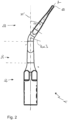
- FIG. 2 shows the tip element 1 in a perspective view parallel to a main plane M including the first bended subsection 31 and the second bended subsection 32.
- the double bended structure of the motion transformation section 30 cannot be observed in this illustration.
- the second end section 20 of the tip element 1 is bended into a tilted direction T relative to the main plane M, including the first bended subsection 31 and the second subsection 32, about a third angle ⁇ 3, wherein the third angle ⁇ 3 is 35° in the shown embodiment. Due to the bending about the third angle ⁇ 3, at least a part of the second end section 20 extends along the tilted direction T for performing a planar flexural motion during utilization of the tip element 1.
- the third angle ⁇ 3 or a corresponding third radius of curvature R ⁇ 3 depends on a planned application of the tip element 1, in particular a region of the mouth the tip element 1 is intended for.
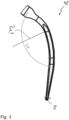
- Figure 3 shows the second end section 20 of the tip element 1 illustrated in the figures 1 and 2 .
- the part of the second end section 20, extending along the tilted direction T is bended about a fourth angle ⁇ 4 and forms a plane including the tilted direction T.
- the fourth angle ⁇ 4 or a corresponding fourth radius of curvature R ⁇ 4 is adapted depending on surfaces to access and preferably ranges between 90° and 135°, more preferably ranges between 110° and 120° and most preferably is mainly 117°.
- a bend of the course of the second end section 20 about the third angle ⁇ 3 is perpendicular to a bend of the course of the second end section 20 about a fourth angle ⁇ 4.
- the geometry of the application part of the tip element (section 20) has a significant influence on the direction of the vibration.
- an anti-axisymmetric structure is retained to limit hammering motions that may be introduced by parasitic motions when the ultrasonic vibration is not controlled.
- the anti-axisymmetric structure gives a preferential direction to the vibration by filtering parasitic motions thanks to a specific quadratic moment, i.e. selective stiffness, and select only the vibration on the rerouted direction.
Landscapes
- Health & Medical Sciences (AREA)
- Dentistry (AREA)
- Epidemiology (AREA)
- Life Sciences & Earth Sciences (AREA)
- Animal Behavior & Ethology (AREA)
- General Health & Medical Sciences (AREA)
- Public Health (AREA)
- Veterinary Medicine (AREA)
- Oral & Maxillofacial Surgery (AREA)
- Dental Tools And Instruments Or Auxiliary Dental Instruments (AREA)
- Surgical Instruments (AREA)
Claims (11)
- Elément d'embout (1), de préférence pour un dispositif de traitement den taire, en particulier un détartreur, l'élément d'embout (1) effectuant une vibra tion ultrasonique pendant son utilisation, comprenant- une première section d'extrémité (10) pour fixer de manière réversible l'élé ment d'embout (1) à une pièce à main,- une deuxième section d'extrémité (20) formant un outil dentaire, et- une section de transformation de mouvement (30) disposée entre la prem ière section d'extrémité (10) et la deuxième section d'extrémité (20),
dans lequelpour transformer une vibration ultrasonique ayant une première direction de vibration (V1) en une vibration ultrasonique ayant une deuxième direction de vibration (V2), la section de transformation de mouvement (30) présente une première sous-section courbée (31) et une deuxième sous-section courbée (32),l'élément d'embout (1) présente un embout pointu, et une course de l'élément d'embout (1) est courbée- d'un premier angle (α1) dans la première sous-section courbée (31) et- d'un deuxième angle (α2) dans la deuxième sous-section courbée (32), sachant que, dans la deuxième section d'extrémité (20), la course de l'élé ment d'embout (1) est courbée dans une direction inclinée (T) d'un troisième angle (α3) par rapport à un plan principal (M) comprenant la première sous-section courbée (31) et la deuxième sous-section courbée (32), et le troisième angle (α3) est compris entre -75° et +75°, de préférence entre -35° et 35°,caractérisé en ce que l'élément d'embout (1) comprend une quantité de titane inférieure à 80 % en poids. - Elément d'embout (1) selon la revendication 1,
dans lequel une différence entre le premier angle (α1) et le deuxième angle (α2) est inférieure à 15°, de préférence inférieure à 5° et plus préféren tiellement inférieure à 2,5°. - Elément d'embout (1) selon la revendication 2,
dans lequel le premier angle (α1) et/ou le deuxième angle (α2) sont compris entre 80° et 140°, de préférence entre 85° et 125° et plus préférentiellement entre 90° et 100°, ou sont même sensiblement de 90°. - Elément d'embout (1) selon l'une des revendications précédentes,dans lequel l'élément d'embout (1) présente une zone centrale (D) et une zone de couverture (S),la zone de couverture (S) entoure la zone centrale (D),le long de la course de l'élément d'embout (1) la zone de couverture (S) mod ifie son extension dans une direction perpendiculaire à la course de l'élément d'embout (S), en particulier dans la section de transformation de mouvement (30).
- Elément d'embout (1) selon la revendication précédente,
dans lequel un premier rayon Rα1 de courbure, satisfaisant à
- Elément d'embout (1) selon l'une des revendications précédentes,
dans lequel la section de transformation de mouvement (30) présente une première longueur (L1), et la course de l'élément d'embout (1) dans la section de transformation de mouvement (30) provoque un déplacement latéral ayant une deuxième longueur (L2), la première longueur (L1) est plus longue que la deuxième longueur (L2). - Elément d'embout (1) selon la revendication 6,
dans lequel la première longueur (L1) et/ou la deuxième longueur (L2) est comprise entre 3 et 8 mm. - Elément d'embout (1) selon la revendication 4,
dans lequel la zone de couverture (S) a une forme conique, en escalier et/ou exponentielle le long de la course de l'élément d'embout (1), en particulier dans la section de transformation de mouvement (30). - Elément d'embout (1) selon l'une des revendications précédentes,
dans lequel, dans la deuxième section d'extrémité (20), la course de l'élé ment d'embout (1) est courbée d'un quatrième angle (α4) dans un plan com prenant une partie de la deuxième section d'extrémité (20) s'étendant dans la direction inclinée (T). - Elément d'embout (1) selon la revendication 6,
dans lequel- la première longueur (L1) est égale ou inférieure à la deuxième longueur (L2), et/ou- la première surface de section transversale (S1) est égale ou inférieure à la deuxième surface de section transversale (S2). - Dispositif de traitement dentaire comprenant un élément d'embout (1) selon l'une des revendications 1 à 10.
Applications Claiming Priority (2)
| Application Number | Priority Date | Filing Date | Title |
|---|---|---|---|
| EP19161409.8A EP3705083B1 (fr) | 2019-03-07 | 2019-03-07 | Élément d'extrémité pour un dispositif de traitement dentaire à ultrasons, section de transformation de mouvement d'un tel dispositif de traitement dentaire, dispositif de traitement dentaire doté d'un tel élément d'extrémité et carte pour contrôler un tel élément d'extrémité |
| PCT/EP2020/055948 WO2020178410A1 (fr) | 2019-03-07 | 2020-03-05 | Élément en pointe destiné à un dispositif de traitement ultrasonore dentaire, section de transformation de mouvement d'un tel dispositif de traitement dentaire, dispositif de traitement dentaire ayant un tel élément en pointe et dispositif carte en pointe pour un tel élément en pointe |
Publications (3)
| Publication Number | Publication Date |
|---|---|
| EP3908227A1 EP3908227A1 (fr) | 2021-11-17 |
| EP3908227B1 true EP3908227B1 (fr) | 2024-11-13 |
| EP3908227C0 EP3908227C0 (fr) | 2024-11-13 |
Family
ID=65724317
Family Applications (2)
| Application Number | Title | Priority Date | Filing Date |
|---|---|---|---|
| EP19161409.8A Active EP3705083B1 (fr) | 2019-03-07 | 2019-03-07 | Élément d'extrémité pour un dispositif de traitement dentaire à ultrasons, section de transformation de mouvement d'un tel dispositif de traitement dentaire, dispositif de traitement dentaire doté d'un tel élément d'extrémité et carte pour contrôler un tel élément d'extrémité |
| EP20707460.0A Active EP3908227B1 (fr) | 2019-03-07 | 2020-03-05 | Pointe pour un dispositif de traitement dentaire à ultrasons et dispositif de traitement dentaire doté d'une telle pointe |
Family Applications Before (1)
| Application Number | Title | Priority Date | Filing Date |
|---|---|---|---|
| EP19161409.8A Active EP3705083B1 (fr) | 2019-03-07 | 2019-03-07 | Élément d'extrémité pour un dispositif de traitement dentaire à ultrasons, section de transformation de mouvement d'un tel dispositif de traitement dentaire, dispositif de traitement dentaire doté d'un tel élément d'extrémité et carte pour contrôler un tel élément d'extrémité |
Country Status (6)
| Country | Link |
|---|---|
| US (1) | US20220133455A1 (fr) |
| EP (2) | EP3705083B1 (fr) |
| JP (2) | JP2022522145A (fr) |
| CN (1) | CN113573664A (fr) |
| ES (1) | ES2874156T3 (fr) |
| WO (1) | WO2020178410A1 (fr) |
Families Citing this family (6)
| Publication number | Priority date | Publication date | Assignee | Title |
|---|---|---|---|---|
| WO2022229090A1 (fr) * | 2021-04-26 | 2022-11-03 | King's College London | Améliorations dans le domaine de la dentisterie |
| US12446996B2 (en) | 2022-12-06 | 2025-10-21 | Linda Lorraine Hodge | Interproximal pick device for a sonic vibration generating handle |
| US12458481B2 (en) | 2022-12-06 | 2025-11-04 | Linda Lorraine Hodge | Method for cleaning teeth |
| USD1056510S1 (en) | 2022-12-06 | 2025-01-07 | Linda Lorraine Hodge | Tapered pick |
| US20260041533A1 (en) * | 2023-08-11 | 2026-02-12 | Dentovations Inc. | Sonication Wand |
| USD1048380S1 (en) * | 2024-03-29 | 2024-10-22 | Touchstone Ego LLC | Dental rinse nozzle |
Citations (1)
| Publication number | Priority date | Publication date | Assignee | Title |
|---|---|---|---|---|
| US20050181328A1 (en) * | 2004-02-17 | 2005-08-18 | Milne Stephanie C. | Ultrasonic scaler tip incorporating a depth gauge |
Family Cites Families (22)
| Publication number | Priority date | Publication date | Assignee | Title |
|---|---|---|---|---|
| JPS53128189A (en) * | 1977-04-13 | 1978-11-08 | Morita Mfg | Supersonic vibrator for removing tartar |
| JPS58133315U (ja) * | 1982-03-02 | 1983-09-08 | 株式会社吉田製作所 | 超音波振動による歯石除去具 |
| CA1335417C (fr) * | 1988-01-06 | 1995-05-02 | George E. Warrin | Instrument de detartrage et de lavage dentaire |
| DE4238384C1 (de) | 1992-11-13 | 1994-05-11 | Erosonic Ag Wattwil | Sonotrode für ein Ultraschall-Bearbeitungsgerät |
| WO1997038644A1 (fr) * | 1996-04-12 | 1997-10-23 | Hakusui Trading Co., Ltd. | Support d'apex dentaire et apex dentaire l'utilisant |
| DE60332597D1 (de) * | 2002-02-15 | 2010-07-01 | Earth City Technologies Inc | Dentalinstrumente zur verwendung mit ultraschallhandstücken |
| FR2876574B1 (fr) * | 2004-10-20 | 2007-11-02 | Patrick Lesage | Insert de taille pour appareil dentaire a vibrations |
| US8114104B2 (en) * | 2006-06-01 | 2012-02-14 | Ethicon Endo-Surgery, Inc. | Mechanism for assembly of ultrasonic instrument |
| JP2010505559A (ja) * | 2006-10-12 | 2010-02-25 | デンツプライ カナダ リミテッド | 歯の異常の検出及び処置に適応可能な装置 |
| US20080248444A1 (en) * | 2007-04-04 | 2008-10-09 | Bahcall James K | Ultrasonic endodontic tip having a low-modulus of elasticity |
| US8523889B2 (en) * | 2007-07-27 | 2013-09-03 | Ethicon Endo-Surgery, Inc. | Ultrasonic end effectors with increased active length |
| KR100935472B1 (ko) * | 2009-03-20 | 2010-01-06 | 주식회사 쎄타텍 | 치과 임플란트용 스케일러 팁 및 그 제조방법 |
| EP2509529B1 (fr) * | 2009-12-10 | 2018-09-19 | Yugen Kaisha Siesta | Embout de détartreur à ultrasons |
| JP5145476B1 (ja) * | 2012-07-30 | 2013-02-20 | 有限会社錦部製作所 | 歯科用チップの摩耗チェッカー |
| US20150245884A1 (en) * | 2012-09-25 | 2015-09-03 | Hu-Friedy Mfg., Llc | Magnetostrictive scaler with phosphor-lighted insert and led-generated visible light block |
| CN103433169B (zh) * | 2013-07-11 | 2015-09-02 | 江苏大学 | 一种高斯复合形角的中频超声雾化喷头及其设计方法 |
| US9820826B2 (en) * | 2014-09-23 | 2017-11-21 | Societe Pour La Conception Des Applications Des Techniques Electroniques | Ultrasonic tip for ultrasonic instrument and method of dental treatment with said ultrasonic tip |
| CN204909697U (zh) * | 2015-07-13 | 2015-12-30 | 桂林市啄木鸟医疗器械有限公司 | 一种超声牙科除垢装置 |
| US20170333169A1 (en) * | 2016-05-19 | 2017-11-23 | Tram Quynh Hoang | Scaler Tips and Implant Cleaning Inserts |
| US20180140403A1 (en) * | 2016-11-22 | 2018-05-24 | Dentsply Sirona Inc. | Molded tip wear gauge |
| CN108420555B (zh) * | 2018-05-23 | 2024-02-02 | 南宁市微牙科技有限公司 | 一种专门用于维护磨牙种植体的工作尖 |
| ES2688969A1 (es) * | 2018-07-10 | 2018-11-07 | Universidade De Santiago De Compostela | Inserto para tratamiento de infecciones buco dentales producidas por biopelículas bacterianas y uso del mismo |
-
2019
- 2019-03-07 EP EP19161409.8A patent/EP3705083B1/fr active Active
- 2019-03-07 ES ES19161409T patent/ES2874156T3/es active Active
-
2020
- 2020-03-05 CN CN202080019182.0A patent/CN113573664A/zh active Pending
- 2020-03-05 EP EP20707460.0A patent/EP3908227B1/fr active Active
- 2020-03-05 JP JP2021549689A patent/JP2022522145A/ja active Pending
- 2020-03-05 WO PCT/EP2020/055948 patent/WO2020178410A1/fr not_active Ceased
- 2020-03-05 US US17/433,255 patent/US20220133455A1/en active Pending
-
2025
- 2025-07-10 JP JP2025116274A patent/JP2025138886A/ja active Pending
Patent Citations (1)
| Publication number | Priority date | Publication date | Assignee | Title |
|---|---|---|---|---|
| US20050181328A1 (en) * | 2004-02-17 | 2005-08-18 | Milne Stephanie C. | Ultrasonic scaler tip incorporating a depth gauge |
Also Published As
| Publication number | Publication date |
|---|---|
| US20220133455A1 (en) | 2022-05-05 |
| JP2022522145A (ja) | 2022-04-14 |
| CN113573664A (zh) | 2021-10-29 |
| EP3705083A1 (fr) | 2020-09-09 |
| WO2020178410A1 (fr) | 2020-09-10 |
| EP3705083B1 (fr) | 2021-03-24 |
| ES2874156T3 (es) | 2021-11-04 |
| EP3908227C0 (fr) | 2024-11-13 |
| EP3908227A1 (fr) | 2021-11-17 |
| JP2025138886A (ja) | 2025-09-25 |
Similar Documents
| Publication | Publication Date | Title |
|---|---|---|
| EP3908227B1 (fr) | Pointe pour un dispositif de traitement dentaire à ultrasons et dispositif de traitement dentaire doté d'une telle pointe | |
| EP1323481B1 (fr) | Couplage des vibrations à une pièce à main ultrasonique | |
| KR101152338B1 (ko) | 초음파 치과용 도구 | |
| EP1257225B1 (fr) | Instrument dentaire manuel | |
| EP1977716A1 (fr) | Extrémité endodontique ultrasonique disposant d'un faible module d'élasticité | |
| US4229168A (en) | Contra-angle ultrasonic endodontic instrument | |
| CN110891517A (zh) | 用于牙根管冲洗和消毒的牙髓系统和器械 | |
| EP4096564B1 (fr) | Outil pour un traitement médical | |
| JP7489539B2 (ja) | 改善された性能耐久性を有する超音波歯科用器具、インサートアセンブリ、及びインサート | |
| EP4096565B1 (fr) | Outil pour un traitement médical | |
| US5816808A (en) | Instrument for periodontic treatment and related method | |
| US20030099917A1 (en) | Piezoelectric dental scaler apparatus | |
| EP2243440A1 (fr) | Instrument à main pour soins dentaires manuels | |
| KR100481851B1 (ko) | 치과용 공구의 입체 절곡구조 | |
| KR100447629B1 (ko) | 치과용 기구의 입체절곡구조 | |
| KR200288962Y1 (ko) | 입체절곡구조를 갖는 치과용 공구 | |
| EP2598077B1 (fr) | Outil activé par transducteur muni d'une conduite d'eau | |
| George | Ultrasonic Instrumentation | |
| Lea et al. | Technology, ultrasonics and dentistry | |
| JP2023551088A (ja) | ツールチップ、そうしたツールチップを備える歯科治療用のツール、及びそうしたツールの動作方法 |
Legal Events
| Date | Code | Title | Description |
|---|---|---|---|
| STAA | Information on the status of an ep patent application or granted ep patent |
Free format text: STATUS: UNKNOWN |
|
| STAA | Information on the status of an ep patent application or granted ep patent |
Free format text: STATUS: THE INTERNATIONAL PUBLICATION HAS BEEN MADE |
|
| PUAI | Public reference made under article 153(3) epc to a published international application that has entered the european phase |
Free format text: ORIGINAL CODE: 0009012 |
|
| STAA | Information on the status of an ep patent application or granted ep patent |
Free format text: STATUS: REQUEST FOR EXAMINATION WAS MADE |
|
| 17P | Request for examination filed |
Effective date: 20210810 |
|
| AK | Designated contracting states |
Kind code of ref document: A1 Designated state(s): AL AT BE BG CH CY CZ DE DK EE ES FI FR GB GR HR HU IE IS IT LI LT LU LV MC MK MT NL NO PL PT RO RS SE SI SK SM TR |
|
| DAV | Request for validation of the european patent (deleted) | ||
| DAX | Request for extension of the european patent (deleted) | ||
| STAA | Information on the status of an ep patent application or granted ep patent |
Free format text: STATUS: EXAMINATION IS IN PROGRESS |
|
| 17Q | First examination report despatched |
Effective date: 20230406 |
|
| GRAP | Despatch of communication of intention to grant a patent |
Free format text: ORIGINAL CODE: EPIDOSNIGR1 |
|
| STAA | Information on the status of an ep patent application or granted ep patent |
Free format text: STATUS: GRANT OF PATENT IS INTENDED |
|
| INTG | Intention to grant announced |
Effective date: 20240612 |
|
| GRAS | Grant fee paid |
Free format text: ORIGINAL CODE: EPIDOSNIGR3 |
|
| GRAA | (expected) grant |
Free format text: ORIGINAL CODE: 0009210 |
|
| STAA | Information on the status of an ep patent application or granted ep patent |
Free format text: STATUS: THE PATENT HAS BEEN GRANTED |
|
| AK | Designated contracting states |
Kind code of ref document: B1 Designated state(s): AL AT BE BG CH CY CZ DE DK EE ES FI FR GB GR HR HU IE IS IT LI LT LU LV MC MK MT NL NO PL PT RO RS SE SI SK SM TR |
|
| REG | Reference to a national code |
Ref country code: GB Ref legal event code: FG4D |
|
| REG | Reference to a national code |
Ref country code: CH Ref legal event code: EP |
|
| REG | Reference to a national code |
Ref country code: DE Ref legal event code: R096 Ref document number: 602020041240 Country of ref document: DE |
|
| REG | Reference to a national code |
Ref country code: IE Ref legal event code: FG4D |
|
| U01 | Request for unitary effect filed |
Effective date: 20241213 |
|
| U07 | Unitary effect registered |
Designated state(s): AT BE BG DE DK EE FI FR IT LT LU LV MT NL PT RO SE SI Effective date: 20241223 |
|
| PG25 | Lapsed in a contracting state [announced via postgrant information from national office to epo] |
Ref country code: HR Free format text: LAPSE BECAUSE OF FAILURE TO SUBMIT A TRANSLATION OF THE DESCRIPTION OR TO PAY THE FEE WITHIN THE PRESCRIBED TIME-LIMIT Effective date: 20241113 Ref country code: IS Free format text: LAPSE BECAUSE OF FAILURE TO SUBMIT A TRANSLATION OF THE DESCRIPTION OR TO PAY THE FEE WITHIN THE PRESCRIBED TIME-LIMIT Effective date: 20250313 |
|
| PG25 | Lapsed in a contracting state [announced via postgrant information from national office to epo] |
Ref country code: ES Free format text: LAPSE BECAUSE OF FAILURE TO SUBMIT A TRANSLATION OF THE DESCRIPTION OR TO PAY THE FEE WITHIN THE PRESCRIBED TIME-LIMIT Effective date: 20241113 |
|
| PG25 | Lapsed in a contracting state [announced via postgrant information from national office to epo] |
Ref country code: NO Free format text: LAPSE BECAUSE OF FAILURE TO SUBMIT A TRANSLATION OF THE DESCRIPTION OR TO PAY THE FEE WITHIN THE PRESCRIBED TIME-LIMIT Effective date: 20250213 |
|
| PG25 | Lapsed in a contracting state [announced via postgrant information from national office to epo] |
Ref country code: GR Free format text: LAPSE BECAUSE OF FAILURE TO SUBMIT A TRANSLATION OF THE DESCRIPTION OR TO PAY THE FEE WITHIN THE PRESCRIBED TIME-LIMIT Effective date: 20250214 |
|
| PG25 | Lapsed in a contracting state [announced via postgrant information from national office to epo] |
Ref country code: PL Free format text: LAPSE BECAUSE OF FAILURE TO SUBMIT A TRANSLATION OF THE DESCRIPTION OR TO PAY THE FEE WITHIN THE PRESCRIBED TIME-LIMIT Effective date: 20241113 |
|
| PG25 | Lapsed in a contracting state [announced via postgrant information from national office to epo] |
Ref country code: RS Free format text: LAPSE BECAUSE OF FAILURE TO SUBMIT A TRANSLATION OF THE DESCRIPTION OR TO PAY THE FEE WITHIN THE PRESCRIBED TIME-LIMIT Effective date: 20250213 |
|
| U20 | Renewal fee for the european patent with unitary effect paid |
Year of fee payment: 6 Effective date: 20250325 |
|
| PG25 | Lapsed in a contracting state [announced via postgrant information from national office to epo] |
Ref country code: SM Free format text: LAPSE BECAUSE OF FAILURE TO SUBMIT A TRANSLATION OF THE DESCRIPTION OR TO PAY THE FEE WITHIN THE PRESCRIBED TIME-LIMIT Effective date: 20241113 |
|
| PGFP | Annual fee paid to national office [announced via postgrant information from national office to epo] |
Ref country code: CH Payment date: 20250401 Year of fee payment: 6 |
|
| PG25 | Lapsed in a contracting state [announced via postgrant information from national office to epo] |
Ref country code: SK Free format text: LAPSE BECAUSE OF FAILURE TO SUBMIT A TRANSLATION OF THE DESCRIPTION OR TO PAY THE FEE WITHIN THE PRESCRIBED TIME-LIMIT Effective date: 20241113 |
|
| PG25 | Lapsed in a contracting state [announced via postgrant information from national office to epo] |
Ref country code: CZ Free format text: LAPSE BECAUSE OF FAILURE TO SUBMIT A TRANSLATION OF THE DESCRIPTION OR TO PAY THE FEE WITHIN THE PRESCRIBED TIME-LIMIT Effective date: 20241113 |
|
| PLBE | No opposition filed within time limit |
Free format text: ORIGINAL CODE: 0009261 |
|
| STAA | Information on the status of an ep patent application or granted ep patent |
Free format text: STATUS: NO OPPOSITION FILED WITHIN TIME LIMIT |
|
| PG25 | Lapsed in a contracting state [announced via postgrant information from national office to epo] |
Ref country code: MC Free format text: LAPSE BECAUSE OF FAILURE TO SUBMIT A TRANSLATION OF THE DESCRIPTION OR TO PAY THE FEE WITHIN THE PRESCRIBED TIME-LIMIT Effective date: 20241113 |
|
| 26N | No opposition filed |
Effective date: 20250814 |
|
| PG25 | Lapsed in a contracting state [announced via postgrant information from national office to epo] |
Ref country code: IE Free format text: LAPSE BECAUSE OF NON-PAYMENT OF DUE FEES Effective date: 20250305 |
|
| REG | Reference to a national code |
Ref country code: CH Ref legal event code: U11 Free format text: ST27 STATUS EVENT CODE: U-0-0-U10-U11 (AS PROVIDED BY THE NATIONAL OFFICE) Effective date: 20260401 |
|
| PGFP | Annual fee paid to national office [announced via postgrant information from national office to epo] |
Ref country code: GB Payment date: 20260324 Year of fee payment: 7 |