EP3908425B1 - Amortissement des vibrations dans une machine-outil à détection multiple des vibrations - Google Patents
Amortissement des vibrations dans une machine-outil à détection multiple des vibrations Download PDFInfo
- Publication number
- EP3908425B1 EP3908425B1 EP20714919.6A EP20714919A EP3908425B1 EP 3908425 B1 EP3908425 B1 EP 3908425B1 EP 20714919 A EP20714919 A EP 20714919A EP 3908425 B1 EP3908425 B1 EP 3908425B1
- Authority
- EP
- European Patent Office
- Prior art keywords
- machine
- value
- controller
- machine tool
- control
- Prior art date
- Legal status (The legal status is an assumption and is not a legal conclusion. Google has not performed a legal analysis and makes no representation as to the accuracy of the status listed.)
- Active
Links
Images


Classifications
-
- H—ELECTRICITY
- H02—GENERATION; CONVERSION OR DISTRIBUTION OF ELECTRIC POWER
- H02K—DYNAMO-ELECTRIC MACHINES
- H02K11/00—Structural association of dynamo-electric machines with electric components or with devices for shielding, monitoring or protection
- H02K11/20—Structural association of dynamo-electric machines with electric components or with devices for shielding, monitoring or protection for measuring, monitoring, testing, protecting or switching
-
- B—PERFORMING OPERATIONS; TRANSPORTING
- B23—MACHINE TOOLS; METAL-WORKING NOT OTHERWISE PROVIDED FOR
- B23Q—DETAILS, COMPONENTS, OR ACCESSORIES FOR MACHINE TOOLS, e.g. ARRANGEMENTS FOR COPYING OR CONTROLLING; MACHINE TOOLS IN GENERAL CHARACTERISED BY THE CONSTRUCTION OF PARTICULAR DETAILS OR COMPONENTS; COMBINATIONS OR ASSOCIATIONS OF METAL-WORKING MACHINES, NOT DIRECTED TO A PARTICULAR RESULT
- B23Q11/00—Accessories fitted to machine tools for keeping tools or parts of the machine in good working condition or for cooling work; Safety devices specially combined with or arranged in, or specially adapted for use in connection with, machine tools
- B23Q11/0032—Arrangements for preventing or isolating vibrations in parts of the machine
-
- G—PHYSICS
- G05—CONTROLLING; REGULATING
- G05B—CONTROL OR REGULATING SYSTEMS IN GENERAL; FUNCTIONAL ELEMENTS OF SUCH SYSTEMS; MONITORING OR TESTING ARRANGEMENTS FOR SUCH SYSTEMS OR ELEMENTS
- G05B19/00—Program-control systems
- G05B19/02—Program-control systems electric
- G05B19/18—Numerical control [NC], i.e. automatically operating machines, in particular machine tools, e.g. in a manufacturing environment, so as to execute positioning, movement or co-ordinated operations by means of program data in numerical form
- G05B19/401—Numerical control [NC], i.e. automatically operating machines, in particular machine tools, e.g. in a manufacturing environment, so as to execute positioning, movement or co-ordinated operations by means of program data in numerical form characterised by control arrangements for measuring, e.g. calibration and initialisation, measuring workpiece for machining purposes
-
- G—PHYSICS
- G05—CONTROLLING; REGULATING
- G05B—CONTROL OR REGULATING SYSTEMS IN GENERAL; FUNCTIONAL ELEMENTS OF SUCH SYSTEMS; MONITORING OR TESTING ARRANGEMENTS FOR SUCH SYSTEMS OR ELEMENTS
- G05B19/00—Program-control systems
- G05B19/02—Program-control systems electric
- G05B19/18—Numerical control [NC], i.e. automatically operating machines, in particular machine tools, e.g. in a manufacturing environment, so as to execute positioning, movement or co-ordinated operations by means of program data in numerical form
- G05B19/404—Numerical control [NC], i.e. automatically operating machines, in particular machine tools, e.g. in a manufacturing environment, so as to execute positioning, movement or co-ordinated operations by means of program data in numerical form characterised by control arrangements for compensation, e.g. for backlash, overshoot, tool offset, tool wear, temperature, machine construction errors, load, inertia
-
- H—ELECTRICITY
- H02—GENERATION; CONVERSION OR DISTRIBUTION OF ELECTRIC POWER
- H02K—DYNAMO-ELECTRIC MACHINES
- H02K11/00—Structural association of dynamo-electric machines with electric components or with devices for shielding, monitoring or protection
- H02K11/30—Structural association with control circuits or drive circuits
-
- H—ELECTRICITY
- H02—GENERATION; CONVERSION OR DISTRIBUTION OF ELECTRIC POWER
- H02K—DYNAMO-ELECTRIC MACHINES
- H02K7/00—Arrangements for handling mechanical energy structurally associated with dynamo-electric machines, e.g. structural association with mechanical driving motors or auxiliary dynamo-electric machines
- H02K7/14—Structural association with mechanical loads, e.g. with hand-held machine tools or fans
-
- G—PHYSICS
- G05—CONTROLLING; REGULATING
- G05B—CONTROL OR REGULATING SYSTEMS IN GENERAL; FUNCTIONAL ELEMENTS OF SUCH SYSTEMS; MONITORING OR TESTING ARRANGEMENTS FOR SUCH SYSTEMS OR ELEMENTS
- G05B2219/00—Program-control systems
- G05B2219/30—Nc systems
- G05B2219/49—Nc machine tool, till multiple
- G05B2219/49054—Active damping of tool vibration
Definitions
- Machine tools can experience unwanted vibrations when machining workpieces.
- the cause of such vibrations known in technical circles as chattering, is inadequately dampened natural frequencies of the machine tool in conjunction with process forces occurring during machining.
- the cutting performance can be reduced, for example by reducing the cutting depth or the feed rate.
- reducing the spindle speed at which the tool is rotated is also effective.
- Such interventions in the operation of the machine tool generally lead to a reduction in productivity and are therefore undesirable.
- the approach is often taken to actively or passively dampen the natural frequencies of the machine in order to avoid having to reduce the cutting performance of the machine tool.
- the corresponding active or passive vibration damper is installed at a suitable location of the machine element whose vibration is to be dampened.
- a sensor is also arranged near the active vibration damper to detect the vibration that occurs.
- this procedure leads to a sufficiently good damping of the vibration at the relevant point. Chattering then no longer occurs. The quality of the surface of the workpiece reaches the desired accuracy. In other cases, however, a significant vibration still remains at the relevant point.
- the pre-processing includes in particular frequency filtering in an appropriately parameterized frequency filter. If necessary, Additional dynamic transfer elements can be present in the control loop to compensate for phase shifts.
- EP 3 017 911 B1 is a dynamically stable machine tool with a ram containing a machine head, several sensors for measuring the intensity of vibrations and at least two inertial actuators, each actuator generating a force in one of the main bending directions of the ram depending on the sensor signals generated by the sensors.
- a processing machine with an axle drive which can be controlled by a control device in accordance with a desired travel movement, wherein the processing machine has a mechanical structure which can be moved by means of the axle drive and on which a compensating drive acting on a compensating mass is arranged.
- the compensating mass can be moved relative to the mechanical structure by means of a control device depending on various measured variables.
- the object of the present invention is to provide a way to achieve an efficient active damping of a unwanted vibration with a stable design of the associated control loop.
- the two actual values are recorded independently of one another using different sensors and are therefore recorded independently of one another. They are therefore also independent of one another in the sense that one actual value cannot simply be derived from the other, as is the case, for example, with position control with a subordinate speed control.
- the change in position i.e. the change in one actual value
- the first setpoint it is possible, and generally desirable, for the first setpoint to have the value zero.
- the first setpoint it is possible for the first setpoint to be determined by the setpoint or actual values of the drives that move the machine elements relative to one another in a position-controlled manner.
- the first setpoint can correspond to a current acceleration that the corresponding machine element is to be subjected to based on the current control of the drives.
- Analogous designs can apply to the second setpoint.
- the resulting manipulated variable of the double controller is a setpoint force. This results in particularly simple control of the active vibration damper.
- a cascaded controller structure is set up, in which the second controller can be parameterized first during commissioning so that it is stable, and then the second controller and the pilot control block can be parameterized so that the double controller is stable as a whole.
- preprocessing of the two recorded actual values is possible.
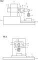
- a machine tool has a plurality of machine elements 1.
- the reference numerals of the machine elements 1 are shown in the FIGS 1 and 2 each supplemented by a small letter a to e so that, if necessary, reference can be made below to a specific machine element 1.
- the machine elements 1 can be moved relative to each other via drives 2 of the machine tool.
- the drives 2 are designed as shown in FIG 3 controlled by a machine control 3, which determines the respective control signals C or the associated setpoint values S* for the drives 2 and outputs them to the drives 2.
- the machine elements 1 are moved relative to one another by the machine control 3 in a position-controlled manner.
- the associated actual values S are determined by the drives 2 reported back to the machine control 3.
- the travel movement causes a tool 4 to be moved relative to a workpiece 5 in a position-controlled manner. During the travel movement, the tool 4 carries out a machining operation on the workpiece 5, for example milling, at least temporarily.
- the machine control 3 is usually designed as a numerical control (CNC).
- the operation of the machine control 3 is determined by a system program 6 and a user program 7.
- the system program 6 usually corresponds to the NC kernel of the numerical control.
- the user program 7 is usually a so-called part program.
- FIGS 1 and 2 show - purely by way of example - a simple design.
- the workpiece table 1a can be moved relative to a base body 1b of the machine tool in a horizontal direction designated x.
- a guide frame 1c can also be present, which can be moved relative to the base body 1b in a vertical direction designated z.
- a support arm 1d in the guide frame 1c can also be moved in a further horizontal direction designated y.
- the further horizontal direction y is generally orthogonal to the previously mentioned horizontal direction x.
- a machining head 1e can be arranged on the support arm 1d, which carries a spindle 8 and the tool 4.
- the machining head 1e can optionally be pivotable about one or two axes.
- undesirable vibrations can occur on various machine elements 1 - for example on the support arm 1d or on the workpiece table 1a. It is assumed below that a vibration occurs on the support arm 1d. However, it could also occur on another of the machine elements 1. As far as reference is made below to the machine element 1 on which the vibration occurs, the reference symbol 1d is therefore used. However, this is only for the purposes of explanation and should not be understood as limiting in the sense that the vibration must occur on the support arm 1d. Furthermore, the corresponding machine element 1d is referred to below as the affected machine element.
- At least one active vibration damper 10 is arranged in a first area 9 of the affected machine element 1d.
- the active vibration damper 10 can be designed as a linear motor, for example.
- the active vibration damper 10 serves to dampen this vibration. The vibration as such does not occur in the first area 9, but in a second area 11 of the affected machine element 1d.
- a first sensor 12 is arranged near the active vibration damper 10 and thus in the first area 9 of the affected machine element 1d.
- a second sensor 13 is additionally present to detect the vibration to be dampened.
- the second sensor 13 can be arranged on another machine element 1, for example on the processing head 1e. It can also be arranged on the affected machine element 1d. In this case, however, the second sensor 13 is arranged in another area of the affected machine element 1d that is different from the first area 9. In particular, the second sensor 13 can be arranged in the second area 11 of the affected machine element 1d in this case. Regardless of the specific arrangement of the second sensor 13, the second sensor 13 is arranged closer to the location at which the Tool 4 acts on the workpiece 5 than the first sensor 12.
- the second sensor 13 can be arranged, for example, on the support arm 1d near the processing head 1e or on the processing head 1e itself, but not on the guide frame 1c or on the base body 1b.
- the sensors 12, 13 can be designed, for example, as acceleration sensors.
- the active vibration damper 10 is controlled by a double controller 14.
- a double controller 14 is a controller to which two actual values I1, I2 and two setpoint values I1*, I2* are fed and which determines a resulting manipulated variable F* based on all four variables I1, I2, I1*, I2* fed to it.
- the double controller 14 is preferably implemented in software. Alternatively, the double controller 14 can be implemented in hardware.
- the double controller 14 it is as shown in FIG 3 It is possible for the double controller 14 to be part of the machine control system 3. Alternatively, it can be implemented independently.
- the drives 2 are often assigned so-called control units (not shown), which convert the control signals C emitted by the machine control system 3 into the control of power converters (not shown), which in turn supply the electrical machines (not shown) with their respective operating current, so that the electrical machines move the machine elements 1.
- the double controller 14 can in particular be implemented in such a control unit.
- a control unit can often control the power converters of several electrical machines, it can possibly be the same control unit that also supplies the electrical machines of the drives 2 with their respective operating current.
- a first actual value I1 and a second actual value I2 are therefore fed to the double controller 14.
- the first actual value I1 is detected by the first sensor 12, the second actual value I2 by the second sensor 13.
- the double controller 14 a first setpoint I1* and a second setpoint I2* are supplied.
- the double controller 14 determines a resulting control variable F* for the active vibration damper 10 based on the recorded first and the recorded second actual value I1, I2 and the first and the second setpoint I1*, I2*.
- the double controller 14 also controls the active vibration damper 10 according to the determined resulting control variable F*.
- the resulting control variable F* can be a setpoint force, for example. This applies both to the basic design according to FIG 3 as well as for the possible embodiments of this principle explained below.
- the first setpoint I1* and the second setpoint I2* have the value zero. However, this is not mandatory. It is alternatively possible that the first setpoint I1* is as shown in FIG 4 has a value that is determined by the setpoint or actual values S*, S of the drives 2, which move the machine elements 1 relative to each other in a position-controlled manner.
- the machine control 3 can have a determination block 15, which uses the setpoint or actual values S*, S to determine an expected instantaneous acceleration of the affected machine element 1d in the first area 9 and specifies this value to the double controller 14 as the first setpoint I1*.
- the determination block 15 can be designed as shown in FIG 4 also determine the second setpoint I2*.
- the second setpoint I2* can also have a value that is determined by the setpoint or actual values S*, S of the drives 2, which move the machine elements 1 relative to one another in a position-controlled manner.
- the determination block 15 can use the setpoint or actual values S*, S to determine an expected instantaneous acceleration of the location at which the second sensor 13 is arranged and specify this value to the double controller 14 as the second setpoint I2*.
- the second Setpoint I2* is determined dynamically by the machine control 3.
- the double controller 14 comprises a first controller 16 and a second controller 17.
- the first setpoint I1* and the first recorded actual value I1 are fed to the first controller 16.
- the first controller 16 uses this to determine a first control variable A1.
- the first controller 16 can have a corresponding internal transfer function for this purpose.
- the second setpoint I2* and the second recorded actual value I2 as well as the first control variable A1 are fed to the second controller 17.
- the second controller 17 uses this to determine a provisional manipulated variable F'*.
- the double controller 14 also has a pilot control block 22.
- the first setpoint I1* and the first recorded actual value I1, in particular their difference, are fed to the pilot control block 22.
- the pilot control block 22 uses this to determine a second control variable A2.
- the double controller 14 switches the second control variable A2 to the provisional manipulated variable F'*.
- the sum of these two variables A2, F'* determined in this way corresponds to the resulting manipulated variable F*.
- the first and second controllers 16, 17 swap roles.
- the first setpoint I1*, the first recorded actual value I1 and a first control variable A1 are fed to the first controller 16.
- the first controller 16 uses this to determine a provisional control variable F'*.
- the second setpoint I2* and the second recorded actual value I2 are fed to the second controller 17.
- the second controller 17 determines the first connection size A1.
- the double controller 14 has a pilot control block 22.
- the second setpoint I2* and the second recorded actual value I2, in particular their difference, are fed to the pilot control block 22.
- the pilot control block 22 uses this to determine a second feedforward variable A2.
- the double controller 14 switches the second feedforward variable A2 to the provisional manipulated variable F'*.
- the sum of these two variables A2, F'* determined in this way corresponds to the resulting manipulated variable F*.
- the present invention relates to the following: Machine elements 1 of a machine tool can be moved relative to one another via drives 2.
- a machine control 3 of the machine tool determines control signals C for the drives 2 and outputs them to the drives 2.
- a tool 4 carrying out a machining operation on a workpiece 5 is moved relative to the workpiece 5 in a position-controlled manner.
- at least one active vibration damper 10 is arranged to dampen a vibration that occurs in a second area 11 of this machine element 1d during the machining of the workpiece 5 by the tool 4.
- a first sensor 12 is arranged at least in the first area 9 of this machine element 1d, and a second sensor 13 is arranged on another machine element 1e or in another area of this machine element 1d.
- Actual values I1, I2 detected by means of the first and second sensors 12, 13 and corresponding target values I1*, I2* are fed to a double controller 14. Based on these values I1, I2, I1*, I2*, the double controller 14 determines a resulting manipulated variable F* for the active vibration damper 10 and controls the active vibration damper 10 accordingly.
- the present invention has many advantages. Due to the arrangement of the first sensor 12 near the active vibration damper 10 and thus the detection of the first By using the first actual value I1 in the vicinity of the active vibration damper 10, stable control can be easily achieved, which can be easily improved by adding the second actual value I2.
- the present invention was explained above in connection with a single active vibration damper 10 which is arranged on a single machine element 1 - here the machine element 1d. However, it is also possible to arrange several active vibration dampers 10 on a single machine element 1. It is also possible to arrange one or more active vibration dampers 10 on several machine elements 1.
Landscapes
- Engineering & Computer Science (AREA)
- Power Engineering (AREA)
- Physics & Mathematics (AREA)
- Manufacturing & Machinery (AREA)
- General Physics & Mathematics (AREA)
- Automation & Control Theory (AREA)
- Human Computer Interaction (AREA)
- Mechanical Engineering (AREA)
- Microelectronics & Electronic Packaging (AREA)
- Feedback Control In General (AREA)
- Automatic Control Of Machine Tools (AREA)
- Control Of Position Or Direction (AREA)
- Auxiliary Devices For Machine Tools (AREA)
Claims (3)
- Machine-outil,- la machine-outil comportant une pluralité d'éléments (1) de machine,- les éléments (1) de machine pouvant être déplacés les uns par rapport aux autres par l'intermédiaire d'entraînements (2) de la machine-outil,- la machine-outil comportant une commande (3) de machine, qui détermine des signaux (C) de commande pour les entraînements (2) et les envoie aux entraînements (2) pour déplacer les éléments (1) de la machine-outil d'une manière réglée en position les uns par rapport aux autres, de sorte qu'un outil (4) effectuant un usinage avec enlèvement de copeaux d'une pièce (5) est déplacé d'une manière réglée en position par rapport à la pièce (5),- au moins un amortisseur (10) actif de vibrations étant disposé dans une première partie (9) de l'un des éléments (1d) de la machine pour amortir une vibration se produisant dans une deuxième partie (11) de cet élément (1d) de la machine pendant l'usinage de la pièce (5) par l'outil (4),- un premier capteur (12) étant monté au moins sur la première partie (9) de cet élément (1d) de la machine pour détecter la vibration à amortir et un deuxième capteur (13) étant monté sur un autre élément (1e) de la machine ou dans une autre partie de cet élément (1d) de la machine, notamment dans la deuxième partie (11) de cet élément (1d) de machine,- une première valeur (I1) réelle détectée au moyen du premier capteur (12) et une deuxième valeur (I2) réelle détectée au moyen du deuxième capteur (13) ainsi qu'une première et une deuxième valeur (I1*, I2*) de consigne étant envoyées à un régulateur double (14),- le double régulateur (14) déterminant, sur la base de la première et de la deuxième valeur (I1, I2) réelle détectées et de la première et de la deuxième valeur (I1*, I2*) de consigne, une grandeur (F*) de régulation résultante de l'amortisseur (10) actif de vibrations et commandant l'amortisseur (10) actif de vibrations en conséquence, caractérisée en ce que :- le double régulateur (14) comporte un premier régulateur (16) auquel sont envoyées la première valeur (I1*) de consigne et la première valeur (I1) réelle détectée et qui détermine sur la base de celles-ci une première grandeur (A1) d'activation, et- le double régulateur (14) comportant un deuxième régulateur (17) auquel sont envoyées la deuxième valeur (I2*) de consigne et la deuxième valeur (I2) réelle détectée ainsi que la première grandeur (Al) d'activation et qui détermine sur la base de celles-ci une grandeur (F'*) de régulation provisoire,- en ce que le régulateur double (14) comporte un bloc (22) pilote, qui reçoit la première valeur (I1*) de consigne et la première valeur (I1) réelle détectée et qui détermine sur la base de celles-ci une deuxième grandeur (A2) d'activation, et en ce que le régulateur double (14) applique la deuxième grandeur (A2) d'activation à la grandeur (F'*) de régulation provisoire et détermine ainsi la grandeur (F*) de régulation résultante.
- Machine-outil suivant la revendication 1,
caractérisée- en ce que la première valeur (I1*) de consigne comporte la valeur zéro ou comporte une valeur qui est déterminée par les valeurs de consigne ou les valeurs réelles (S*, S) des entraînements (2) qui déplacent les éléments (1) de la machine les uns par rapport aux autres d'une manière réglée en position et/ou- en ce que la deuxième valeur (I2*) de consigne comporte la valeur zéro ou comporte une valeur qui est déterminée par les valeurs de consigne ou les valeurs réelles (S*, S) des entraînements (2) qui déplacent les éléments (1) de la machine les uns par rapport aux autres d'une manière réglée en position. - Machine-outil suivant la revendication 1 ou 2,
caractérisée
en ce que la grandeur (F*) de régulation résultante du double régulateur (14) est une force de consigne.
Applications Claiming Priority (2)
| Application Number | Priority Date | Filing Date | Title |
|---|---|---|---|
| EP19165141.3A EP3715049A1 (fr) | 2019-03-26 | 2019-03-26 | Amortissement des vibrations dans une machine-outil à détection multiple des vibrations |
| PCT/EP2020/057194 WO2020193265A1 (fr) | 2019-03-26 | 2020-03-17 | Amortissement de vibrations pour une machine-outil avec détection multiple de vibrations |
Publications (3)
| Publication Number | Publication Date |
|---|---|
| EP3908425A1 EP3908425A1 (fr) | 2021-11-17 |
| EP3908425C0 EP3908425C0 (fr) | 2024-07-17 |
| EP3908425B1 true EP3908425B1 (fr) | 2024-07-17 |
Family
ID=66182333
Family Applications (2)
| Application Number | Title | Priority Date | Filing Date |
|---|---|---|---|
| EP19165141.3A Withdrawn EP3715049A1 (fr) | 2019-03-26 | 2019-03-26 | Amortissement des vibrations dans une machine-outil à détection multiple des vibrations |
| EP20714919.6A Active EP3908425B1 (fr) | 2019-03-26 | 2020-03-17 | Amortissement des vibrations dans une machine-outil à détection multiple des vibrations |
Family Applications Before (1)
| Application Number | Title | Priority Date | Filing Date |
|---|---|---|---|
| EP19165141.3A Withdrawn EP3715049A1 (fr) | 2019-03-26 | 2019-03-26 | Amortissement des vibrations dans une machine-outil à détection multiple des vibrations |
Country Status (4)
| Country | Link |
|---|---|
| US (1) | US12088150B2 (fr) |
| EP (2) | EP3715049A1 (fr) |
| CN (1) | CN113646131B (fr) |
| WO (1) | WO2020193265A1 (fr) |
Families Citing this family (4)
| Publication number | Priority date | Publication date | Assignee | Title |
|---|---|---|---|---|
| EP3928921A1 (fr) * | 2020-06-24 | 2021-12-29 | Siemens Aktiengesellschaft | Machine-outil |
| EP3929677A1 (fr) | 2020-06-24 | 2021-12-29 | Siemens Aktiengesellschaft | Système d'amortissement de vibrations et machine-outil |
| DE102021103106A1 (de) * | 2021-02-10 | 2022-08-11 | Homag Gmbh | Bearbeitungsvorrichtung sowie Verfahren zum Betrieb einer Bearbeitungsvorrichtung |
| DE102023128209A1 (de) | 2023-10-16 | 2025-04-17 | Abacus neo GmbH | Schwingungsüberwachung mit aktiver Dämpfung |
Family Cites Families (23)
| Publication number | Priority date | Publication date | Assignee | Title |
|---|---|---|---|---|
| US5816122A (en) * | 1996-04-30 | 1998-10-06 | General Dynamics Advanced Technology Systems, Inc. | Apparatus and method for adaptive suppression of vibrations in mechanical systems |
| US6296093B1 (en) * | 1998-11-09 | 2001-10-02 | Lord Corportion | Vibration-damped machine and control method therefor |
| CZ302554B6 (cs) | 2000-10-26 | 2011-07-13 | Heidelberger Druckmaschinen Ag | Zpusob kompenzace mechanického kmitání, zejména v tiskarských strojích |
| DE10246093C1 (de) * | 2002-10-02 | 2003-11-27 | Siemens Ag | Verfahren zur Dämpfung mechanischer Schwingungen von Achsen von Werkzeugmaschinen, Produktionsmaschinen oder Robotern |
| DE10301765A1 (de) | 2003-01-18 | 2004-07-29 | Dr. Johannes Heidenhain Gmbh | Reglerstruktur zur aktiven Dämpfung niederfrequenter Schwingungen an numerisch gesteuerten Werkzeugmaschinen |
| FR2856765B1 (fr) | 2003-06-26 | 2005-12-02 | Hutchinson | Batteur dynamique actif |
| JP2005075641A (ja) | 2003-08-29 | 2005-03-24 | Tietech Co Ltd | 振動フィーダの停止方法 |
| DE102008052058B3 (de) | 2008-10-17 | 2009-11-12 | Iav Gmbh Ingenieurgesellschaft Auto Und Verkehr | Dämpfungseinrichtung und Dämpfungsverfahren zur Unterdrückung von Torsionsschwingungen im Antriebsstrang von Kraftfahrzeugen |
| CN101702093A (zh) * | 2009-10-09 | 2010-05-05 | 江苏大学 | 一种振动结构辐射噪声的有源控制系统及控制方法 |
| ES2398814B1 (es) | 2009-10-23 | 2014-01-29 | Universidad De Burgos | Dispositivo inteligente y procedimiento para la compensación de caídas de carnero en máquinas herramienta |
| FR2967508B1 (fr) | 2010-11-16 | 2014-02-21 | Ixmotion | Procede et dispositif de controle actif de vibrations mecaniques par mise en oeuvre d'une loi de controle constituee d'un correcteur central et d'un parametre de youla |
| EP2574820B1 (fr) * | 2011-09-30 | 2014-04-16 | Siemens Aktiengesellschaft | Machine de traitement dotée de structures mécaniques mobiles à compensation d'oscillations |
| EP2574821B1 (fr) * | 2011-09-30 | 2013-10-30 | Siemens Aktiengesellschaft | Amortisseur d'oscillations actif sans détection d'accélération directe |
| DE102012201562A1 (de) | 2012-02-02 | 2013-08-08 | Dr. Johannes Heidenhain Gmbh | Reglerstruktur zur Dämpfung niederfrequenter Schwingungen |
| ES2769304T3 (es) | 2012-04-05 | 2020-06-25 | Fidia Spa | Dispositivo para corrección de errores para máquinas CNC |
| CN103372787A (zh) | 2012-04-28 | 2013-10-30 | 台中精机厂股份有限公司 | 工具机智能化适应性切削振动抑制方法与系统 |
| CN103447617B (zh) | 2013-07-23 | 2016-04-06 | 杭州电子科技大学 | 一种基于主振模态预测的带锯条振动主动抑制装置及方法 |
| ES2630952T3 (es) * | 2014-11-05 | 2017-08-25 | Ideko, S.Coop. | Máquina herramienta dinámicamente estable |
| CN105436981B (zh) | 2015-09-28 | 2018-02-16 | 上海诺倬力机电科技有限公司 | 基于振动监测的颤振控制方法及数控加工装置 |
| IT201600105106A1 (it) * | 2016-10-19 | 2018-04-19 | Hsd S P A | Sistema di smorzamento di vibrazioni per una testa operatrice di una macchina utensile, e corrispondente testa operatrice |
| CN106903547B (zh) | 2017-04-20 | 2023-03-28 | 中南大学 | 适用于高速铣削加工的电主轴主动振动控制装置及系统 |
| EP3708297A1 (fr) * | 2019-03-14 | 2020-09-16 | Siemens Aktiengesellschaft | Commande optimisée d'un amortisseur de vibrations actif |
| EP3929677A1 (fr) * | 2020-06-24 | 2021-12-29 | Siemens Aktiengesellschaft | Système d'amortissement de vibrations et machine-outil |
-
2019
- 2019-03-26 EP EP19165141.3A patent/EP3715049A1/fr not_active Withdrawn
-
2020
- 2020-03-17 US US17/442,957 patent/US12088150B2/en active Active
- 2020-03-17 WO PCT/EP2020/057194 patent/WO2020193265A1/fr not_active Ceased
- 2020-03-17 EP EP20714919.6A patent/EP3908425B1/fr active Active
- 2020-03-17 CN CN202080024680.4A patent/CN113646131B/zh active Active
Also Published As
| Publication number | Publication date |
|---|---|
| EP3908425C0 (fr) | 2024-07-17 |
| US12088150B2 (en) | 2024-09-10 |
| CN113646131B (zh) | 2024-07-26 |
| US20220190689A1 (en) | 2022-06-16 |
| EP3715049A1 (fr) | 2020-09-30 |
| EP3908425A1 (fr) | 2021-11-17 |
| CN113646131A (zh) | 2021-11-12 |
| WO2020193265A1 (fr) | 2020-10-01 |
Similar Documents
| Publication | Publication Date | Title |
|---|---|---|
| EP3908425B1 (fr) | Amortissement des vibrations dans une machine-outil à détection multiple des vibrations | |
| DE102016104515B4 (de) | Numerische Steuervorrichtung und Steuerverfahren | |
| DE102017207822B4 (de) | Vorrichtung zur verarbeitung eines bearbeitungsprogramms und damit ausgestattete mehrachsige bearbeitungsmaschine | |
| WO2008049764A1 (fr) | Machine-outil | |
| DE102015111964B4 (de) | Servomotoren-Steuersystem, das die Bearbeitungspräzision mehrerer Achsen verbessert | |
| DE102010007888A1 (de) | Verfahren und Vorrichtung zur Herstellung eines Biegeteils | |
| DE102012205423A1 (de) | Verfahren und Programm zum Berechnen eines Korrekturwerts für eine Werkzeugmaschine | |
| DE102012101979B4 (de) | Verfahren und Vorrichtung zur Erzeugung einer Relativbewegung | |
| EP2156252A1 (fr) | Machine de mesure ou machine-outil à arbres redondants à action translatoire pour mouvement continu sur des trajectoires complexes | |
| DE102009038155B4 (de) | Servomotorsteuergerät | |
| DE102015008740B4 (de) | Robotersteuerungsvorrichtung, die in der lage ist, ein werkstück mit einem parameter zu befördern, der einen soll-werkstückparatmeter überschreitet | |
| AT512802B1 (de) | Positionsausgleichssystem in einem Transferzentrum zur spanenden Bearbeitung von Werkstücken | |
| DE102008050863B4 (de) | Positionssteuerungsvorrichtung | |
| EP0088212A1 (fr) | Commande numérique pour machines-outils | |
| EP3955073A1 (fr) | Fonctionnement d'une machine-outil au moins à deux axes | |
| EP1977295B1 (fr) | Procédé de réglage d'axes | |
| DE10359984B4 (de) | Verfahren und Einrichtung zur Bewegungsführung eines bewegbaren Maschinenelements einer Werkzeug- oder Produktionsmaschine | |
| DE102017011602B4 (de) | Numerische Steuerung | |
| EP3708297A1 (fr) | Commande optimisée d'un amortisseur de vibrations actif | |
| DE112021001684T5 (de) | Vorrichtung zur unterstützung der geschwindigkeitsregulierung | |
| DE102019130239A1 (de) | Parametereinstellvorrichtung, system und parameter-einstellverfahren | |
| DE102008007292A1 (de) | Positionsregler und Verfahren zur Positionsregelung eines Werkzeugs | |
| DE10023973A1 (de) | Aktive Spindellagerung | |
| EP3792716B1 (fr) | Commande numérique pourvue de mise en mémoire tampon des valeurs de consigne de position | |
| DE102015221660A1 (de) | Numerisch gesteuerte werkzeugmaschine |
Legal Events
| Date | Code | Title | Description |
|---|---|---|---|
| STAA | Information on the status of an ep patent application or granted ep patent |
Free format text: STATUS: UNKNOWN |
|
| STAA | Information on the status of an ep patent application or granted ep patent |
Free format text: STATUS: THE INTERNATIONAL PUBLICATION HAS BEEN MADE |
|
| PUAI | Public reference made under article 153(3) epc to a published international application that has entered the european phase |
Free format text: ORIGINAL CODE: 0009012 |
|
| STAA | Information on the status of an ep patent application or granted ep patent |
Free format text: STATUS: REQUEST FOR EXAMINATION WAS MADE |
|
| 17P | Request for examination filed |
Effective date: 20210811 |
|
| AK | Designated contracting states |
Kind code of ref document: A1 Designated state(s): AL AT BE BG CH CY CZ DE DK EE ES FI FR GB GR HR HU IE IS IT LI LT LU LV MC MK MT NL NO PL PT RO RS SE SI SK SM TR |
|
| DAV | Request for validation of the european patent (deleted) | ||
| DAX | Request for extension of the european patent (deleted) | ||
| STAA | Information on the status of an ep patent application or granted ep patent |
Free format text: STATUS: EXAMINATION IS IN PROGRESS |
|
| 17Q | First examination report despatched |
Effective date: 20220714 |
|
| GRAP | Despatch of communication of intention to grant a patent |
Free format text: ORIGINAL CODE: EPIDOSNIGR1 |
|
| STAA | Information on the status of an ep patent application or granted ep patent |
Free format text: STATUS: GRANT OF PATENT IS INTENDED |
|
| RIC1 | Information provided on ipc code assigned before grant |
Ipc: G05B 19/404 20060101ALI20240306BHEP Ipc: G05B 19/401 20060101ALI20240306BHEP Ipc: B23Q 11/00 20060101AFI20240306BHEP |
|
| INTG | Intention to grant announced |
Effective date: 20240322 |
|
| GRAS | Grant fee paid |
Free format text: ORIGINAL CODE: EPIDOSNIGR3 |
|
| GRAA | (expected) grant |
Free format text: ORIGINAL CODE: 0009210 |
|
| STAA | Information on the status of an ep patent application or granted ep patent |
Free format text: STATUS: THE PATENT HAS BEEN GRANTED |
|
| AK | Designated contracting states |
Kind code of ref document: B1 Designated state(s): AL AT BE BG CH CY CZ DE DK EE ES FI FR GB GR HR HU IE IS IT LI LT LU LV MC MK MT NL NO PL PT RO RS SE SI SK SM TR |
|
| REG | Reference to a national code |
Ref country code: CH Ref legal event code: EP |
|
| REG | Reference to a national code |
Ref country code: DE Ref legal event code: R096 Ref document number: 502020008592 Country of ref document: DE |
|
| REG | Reference to a national code |
Ref country code: IE Ref legal event code: FG4D Free format text: LANGUAGE OF EP DOCUMENT: GERMAN |
|
| U01 | Request for unitary effect filed |
Effective date: 20240717 |
|
| U07 | Unitary effect registered |
Designated state(s): AT BE BG DE DK EE FI FR IT LT LU LV MT NL PT RO SE SI Effective date: 20240902 |
|
| PG25 | Lapsed in a contracting state [announced via postgrant information from national office to epo] |
Ref country code: NO Free format text: LAPSE BECAUSE OF FAILURE TO SUBMIT A TRANSLATION OF THE DESCRIPTION OR TO PAY THE FEE WITHIN THE PRESCRIBED TIME-LIMIT Effective date: 20241017 |
|
| PG25 | Lapsed in a contracting state [announced via postgrant information from national office to epo] |
Ref country code: GR Free format text: LAPSE BECAUSE OF FAILURE TO SUBMIT A TRANSLATION OF THE DESCRIPTION OR TO PAY THE FEE WITHIN THE PRESCRIBED TIME-LIMIT Effective date: 20241018 Ref country code: PL Free format text: LAPSE BECAUSE OF FAILURE TO SUBMIT A TRANSLATION OF THE DESCRIPTION OR TO PAY THE FEE WITHIN THE PRESCRIBED TIME-LIMIT Effective date: 20240717 |
|
| PG25 | Lapsed in a contracting state [announced via postgrant information from national office to epo] |
Ref country code: IS Free format text: LAPSE BECAUSE OF FAILURE TO SUBMIT A TRANSLATION OF THE DESCRIPTION OR TO PAY THE FEE WITHIN THE PRESCRIBED TIME-LIMIT Effective date: 20241117 |
|
| PG25 | Lapsed in a contracting state [announced via postgrant information from national office to epo] |
Ref country code: HR Free format text: LAPSE BECAUSE OF FAILURE TO SUBMIT A TRANSLATION OF THE DESCRIPTION OR TO PAY THE FEE WITHIN THE PRESCRIBED TIME-LIMIT Effective date: 20240717 |
|
| PG25 | Lapsed in a contracting state [announced via postgrant information from national office to epo] |
Ref country code: RS Free format text: LAPSE BECAUSE OF FAILURE TO SUBMIT A TRANSLATION OF THE DESCRIPTION OR TO PAY THE FEE WITHIN THE PRESCRIBED TIME-LIMIT Effective date: 20241017 Ref country code: ES Free format text: LAPSE BECAUSE OF FAILURE TO SUBMIT A TRANSLATION OF THE DESCRIPTION OR TO PAY THE FEE WITHIN THE PRESCRIBED TIME-LIMIT Effective date: 20240717 |
|
| PG25 | Lapsed in a contracting state [announced via postgrant information from national office to epo] |
Ref country code: RS Free format text: LAPSE BECAUSE OF FAILURE TO SUBMIT A TRANSLATION OF THE DESCRIPTION OR TO PAY THE FEE WITHIN THE PRESCRIBED TIME-LIMIT Effective date: 20241017 Ref country code: PL Free format text: LAPSE BECAUSE OF FAILURE TO SUBMIT A TRANSLATION OF THE DESCRIPTION OR TO PAY THE FEE WITHIN THE PRESCRIBED TIME-LIMIT Effective date: 20240717 Ref country code: NO Free format text: LAPSE BECAUSE OF FAILURE TO SUBMIT A TRANSLATION OF THE DESCRIPTION OR TO PAY THE FEE WITHIN THE PRESCRIBED TIME-LIMIT Effective date: 20241017 Ref country code: IS Free format text: LAPSE BECAUSE OF FAILURE TO SUBMIT A TRANSLATION OF THE DESCRIPTION OR TO PAY THE FEE WITHIN THE PRESCRIBED TIME-LIMIT Effective date: 20241117 Ref country code: HR Free format text: LAPSE BECAUSE OF FAILURE TO SUBMIT A TRANSLATION OF THE DESCRIPTION OR TO PAY THE FEE WITHIN THE PRESCRIBED TIME-LIMIT Effective date: 20240717 Ref country code: GR Free format text: LAPSE BECAUSE OF FAILURE TO SUBMIT A TRANSLATION OF THE DESCRIPTION OR TO PAY THE FEE WITHIN THE PRESCRIBED TIME-LIMIT Effective date: 20241018 Ref country code: ES Free format text: LAPSE BECAUSE OF FAILURE TO SUBMIT A TRANSLATION OF THE DESCRIPTION OR TO PAY THE FEE WITHIN THE PRESCRIBED TIME-LIMIT Effective date: 20240717 |
|
| PG25 | Lapsed in a contracting state [announced via postgrant information from national office to epo] |
Ref country code: SM Free format text: LAPSE BECAUSE OF FAILURE TO SUBMIT A TRANSLATION OF THE DESCRIPTION OR TO PAY THE FEE WITHIN THE PRESCRIBED TIME-LIMIT Effective date: 20240717 |
|
| U20 | Renewal fee for the european patent with unitary effect paid |
Year of fee payment: 6 Effective date: 20250320 |
|
| PG25 | Lapsed in a contracting state [announced via postgrant information from national office to epo] |
Ref country code: CZ Free format text: LAPSE BECAUSE OF FAILURE TO SUBMIT A TRANSLATION OF THE DESCRIPTION OR TO PAY THE FEE WITHIN THE PRESCRIBED TIME-LIMIT Effective date: 20240717 |
|
| PG25 | Lapsed in a contracting state [announced via postgrant information from national office to epo] |
Ref country code: SK Free format text: LAPSE BECAUSE OF FAILURE TO SUBMIT A TRANSLATION OF THE DESCRIPTION OR TO PAY THE FEE WITHIN THE PRESCRIBED TIME-LIMIT Effective date: 20240717 |
|
| PLBE | No opposition filed within time limit |
Free format text: ORIGINAL CODE: 0009261 |
|
| STAA | Information on the status of an ep patent application or granted ep patent |
Free format text: STATUS: NO OPPOSITION FILED WITHIN TIME LIMIT |
|
| 26N | No opposition filed |
Effective date: 20250422 |
|
| PG25 | Lapsed in a contracting state [announced via postgrant information from national office to epo] |
Ref country code: MC Free format text: LAPSE BECAUSE OF FAILURE TO SUBMIT A TRANSLATION OF THE DESCRIPTION OR TO PAY THE FEE WITHIN THE PRESCRIBED TIME-LIMIT Effective date: 20240717 |
|
| REG | Reference to a national code |
Ref country code: CH Ref legal event code: H13 Free format text: ST27 STATUS EVENT CODE: U-0-0-H10-H13 (AS PROVIDED BY THE NATIONAL OFFICE) Effective date: 20251023 |
|
| GBPC | Gb: european patent ceased through non-payment of renewal fee |
Effective date: 20250317 |
|
| PG25 | Lapsed in a contracting state [announced via postgrant information from national office to epo] |
Ref country code: GB Free format text: LAPSE BECAUSE OF NON-PAYMENT OF DUE FEES Effective date: 20250317 |
|
| PG25 | Lapsed in a contracting state [announced via postgrant information from national office to epo] |
Ref country code: CH Free format text: LAPSE BECAUSE OF NON-PAYMENT OF DUE FEES Effective date: 20250331 |
|
| PG25 | Lapsed in a contracting state [announced via postgrant information from national office to epo] |
Ref country code: IE Free format text: LAPSE BECAUSE OF NON-PAYMENT OF DUE FEES Effective date: 20250317 |