EP3908499B1 - Colonne de direction pour un véhicule automobile - Google Patents
Colonne de direction pour un véhicule automobile Download PDFInfo
- Publication number
- EP3908499B1 EP3908499B1 EP20700253.6A EP20700253A EP3908499B1 EP 3908499 B1 EP3908499 B1 EP 3908499B1 EP 20700253 A EP20700253 A EP 20700253A EP 3908499 B1 EP3908499 B1 EP 3908499B1
- Authority
- EP
- European Patent Office
- Prior art keywords
- locking
- engagement element
- longitudinal direction
- locking elements
- steering column
- Prior art date
- Legal status (The legal status is an assumption and is not a legal conclusion. Google has not performed a legal analysis and makes no representation as to the accuracy of the status listed.)
- Active
Links
Images

Classifications
-
- B—PERFORMING OPERATIONS; TRANSPORTING
- B62—LAND VEHICLES FOR TRAVELLING OTHERWISE THAN ON RAILS
- B62D—MOTOR VEHICLES; TRAILERS
- B62D1/00—Steering controls, i.e. means for initiating a change of direction of the vehicle
- B62D1/02—Steering controls, i.e. means for initiating a change of direction of the vehicle vehicle-mounted
- B62D1/16—Steering columns
- B62D1/18—Steering columns yieldable or adjustable, e.g. tiltable
- B62D1/184—Mechanisms for locking columns at selected positions
-
- B—PERFORMING OPERATIONS; TRANSPORTING
- B62—LAND VEHICLES FOR TRAVELLING OTHERWISE THAN ON RAILS
- B62D—MOTOR VEHICLES; TRAILERS
- B62D1/00—Steering controls, i.e. means for initiating a change of direction of the vehicle
- B62D1/02—Steering controls, i.e. means for initiating a change of direction of the vehicle vehicle-mounted
- B62D1/16—Steering columns
- B62D1/18—Steering columns yieldable or adjustable, e.g. tiltable
- B62D1/19—Steering columns yieldable or adjustable, e.g. tiltable incorporating energy-absorbing arrangements, e.g. by being yieldable or collapsible
- B62D1/192—Yieldable or collapsible columns
-
- B—PERFORMING OPERATIONS; TRANSPORTING
- B62—LAND VEHICLES FOR TRAVELLING OTHERWISE THAN ON RAILS
- B62D—MOTOR VEHICLES; TRAILERS
- B62D1/00—Steering controls, i.e. means for initiating a change of direction of the vehicle
- B62D1/02—Steering controls, i.e. means for initiating a change of direction of the vehicle vehicle-mounted
- B62D1/16—Steering columns
- B62D1/18—Steering columns yieldable or adjustable, e.g. tiltable
- B62D1/19—Steering columns yieldable or adjustable, e.g. tiltable incorporating energy-absorbing arrangements, e.g. by being yieldable or collapsible
- B62D1/195—Yieldable supports for the steering column
Definitions
- the invention relates to a steering column for a motor vehicle, comprising an outer casing unit which can be connected directly or indirectly to the body of a motor vehicle and in which a casing tube is held so as to be adjustable in the longitudinal direction, in which a steering spindle is mounted so as to be rotatable about its longitudinal axis, and a clamping device which can be brought into a fixing position in which it fixes the casing unit relative to the casing tube, and into a release position in which it enables adjustment of the casing tube relative to the casing unit at least in the longitudinal direction, wherein the clamping device has an engagement element which extends in the longitudinal direction and is supported on the casing tube, with an upper side and lateral edge sides lying parallel to the longitudinal axis, and a locking element which is supported in the longitudinal direction on the casing unit and which can be moved by the clamping device against the engagement element in the normal direction of the upper side in order to adjust the fixing position, wherein complementary form-fitting elements formed on the locking element and the engagement element can be brought into
- Steering columns in various designs are known in the art for adjusting the steering wheel position to the seating position of the driver of a motor vehicle.
- the steering wheel attached to the rear end of the steering spindle can be positioned longitudinally in the vehicle interior by adjusting the longitudinal axis of the steering column.
- the length adjustability is achieved by an inner jacket tube, in which the steering spindle is rotatably mounted, being telescopically extendable in the longitudinal direction relative to an outer jacket unit and being able to be locked in different longitudinal positions, i.e. releasably fixed, by means of a releasable clamping device.
- the clamping device also referred to as a fixing or locking device, acts on the jacket unit held on the body, whereby in the open state of the clamping device - referred to as the release position or release position - a displacement of the jacket tube in the jacket unit to adjust the steering wheel position.
- a clamping stroke is generated for locking, so that in the closed state - also called the fixing position or locking position - the casing tube is clamped in the casing unit and the steering wheel position is fixed under the expected mechanical stresses during normal driving.
- an energy absorption device is coupled between the casing unit and the casing tube, which are fixed together by the clamping device during normal operation, but are pushed together relative to one another in the event of a crash. This converts the introduced kinetic energy into plastic deformation of an energy absorption element, for example by tearing open a tear tab or bending or squeezing an elongated deformation element, such as a bending wire or bending strip.
- a generic steering column is in the DE 10 2016 220 531 A1 described.
- the clamping device described therein comprises an engagement element attached to the casing tube, which is designed as a toothed plate extending in the longitudinal direction.
- the toothed plate has an upper side with a normal direction perpendicular to the longitudinal direction.
- form-locking elements protruding in the normal direction are designed in the form of a toothing, with a plurality of teeth running transversely to the longitudinal direction.
- a locking element is supported in the longitudinal direction on the outer casing unit and is designed as a toothed stone, which has a toothing on its front side facing the upper side of the engagement element, which corresponds to the said toothing of the engagement element.
- the locking element is moved in the normal direction towards the upper side of the engagement element by the clamping stroke of the clamping device until the front side comes into contact with the upper side and the form-locking elements on the locking and engagement element engage with one another to form a form-locking effect in the longitudinal direction.
- the locking element is lifted from the engagement element by the clamping device in the opposite direction to the normal direction, so that the positive locking of the gears is released and the casing tube can be moved in the longitudinal direction to adjust the steering wheel position in the casing unit.
- the engagement element is connected to the inner casing tube via an energy absorption device, which forms a rigid connection between the outer casing unit and the inner casing tube during normal operation.
- an energy absorption device which forms a rigid connection between the outer casing unit and the inner casing tube during normal operation.
- a steering column of the type mentioned above is known from US 2017/320513 A1 known.
- the disadvantage is the complex manufacturing process for inserting the teeth into the top of the engagement element. Machining results in high tool wear and time expenditure.
- the effective holding force of the form-locking depends on the profile height of the form-locking elements in the normal direction and the engagement force exerted in the normal direction on the locking element for fixing by the clamping device.
- the width of the top side is given by the dimension transverse to the normal and longitudinal direction between the edge sides.
- the height of the edge sides corresponds to the dimension transverse to the longitudinal direction, in the normal direction.
- the engagement element can have a flat, approximately rectangular cross-section in which the width is greater than the height.
- form-locking elements are formed on the two edge sides and protrude on both sides of the engagement element transversely to the longitudinal and normal direction. It can be provided that the form-locking elements of the two edge sides are formed symmetrically to one another. Alternatively, it is also conceivable and possible that the form-locking elements of the two edge sides are formed asymmetrically to one another.
- an area free of form-locking elements can be provided on the upper side of the engagement element, which area amounts to at least 20% of the width of the engagement element.
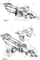
- Figures 1 and 2 show in perspective view obliquely from behind - in relation to the direction of travel of a motor vehicle not shown here - a steering column 1 which has a support unit 2, with fastening means 21 for connection to the body of the motor vehicle (not shown), for example, as shown, fastening openings with different diameters for improved installation in the motor vehicle.
- Two opposing side cheeks 22 and 23 extend downwards from the support unit 2.
- a lifting disk 43 is connected in a rotationally fixed manner to the actuating lever 42 and is designed as a cam disk with cams projecting axially from the outside against the side cheek 22 in the axial direction of the clamping bolt 41, i.e. the clamping axis S.
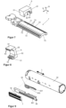
- the locking element 6 has two side arms 61 which are directed against the normal direction N towards the upper side 71.
- Figure 6 shows a view from the top side 71.
- form-locking elements 63 are arranged, which are designed to be complementary to the form-locking elements 73 on the engagement element 7.
- teeth running transversely to the longitudinal axis L are formed on the inner sides 62, which can engage in a form-locking manner in the toothing of the engagement element 7 to produce a form-locking effect in the direction of the longitudinal axis L.
- the form-locking elements 63 are convex as arcuate teeth towards the front ends of the side arms 61. In their course, they have a variable inclination against the normal direction N, from a parallel position to an orientation lying essentially transversely to the normal direction N.
- inclined inclined surfaces D are taken up at least in sections, which in Figure 6 as in the Figures 4 and 5 are shown schematically.
- the form-locking elements 63 engage the corresponding form-locking elements of the engagement element 7 at the edge to form a form-locking connection effective in the longitudinal direction.
- the engagement element 7 is at least partially received between the side arms 61 in cross-section.
- the locking element 6 is also fixed in a form-locking manner on the engagement element 7 transversely to the longitudinal axis L. Due to the convex shape, the arrangement is insensitive to minor misalignments.
- the engagement element 7 On its underside facing away from the upper side 61, the engagement element 7 has a guide groove 75 extending in the longitudinal direction as a guide means.
- an engagement element 7 which has form-locking elements 73 on its two edge sides 61, which protrude transversely to the normal direction N and are each designed as a straight toothing with straight teeth running parallel to the normal direction N.
- the matching locking element 6 has form-locking elements 63 on the inner sides of the side arms 61, which are directed towards one another in the form of a corresponding toothing, the tooth flanks of which also run parallel to the normal direction N.
- the locking part 6 is removed from the Figure 6 shown release or release position is moved by means of the clamping device 4 against the normal direction N towards the upper side 71 until the engagement element 7 is received between the side arms 61 and the form-locking elements 63 and 73 engage with one another to form a form-locking connection effective in the longitudinal direction.
- the locking element 6 is also held in a form-locking manner on the engagement element 7 transversely to the longitudinal direction.
- the energy absorption element 81 is as in Figures 1 and 2 visibly received.
- the engagement element 7 sits with the guide groove 75 on a holding section 811 of the energy absorption element 81, which has a smaller width than the width of the said guide groove 75.
- the holding section 811 is followed by a deformation section 812, which has a greater width than the inner width of the guide groove 75.
- the engagement element 7 can have a guide groove constriction 751, which is also designed as a deformation element and deforms the energy absorption element 81 when the engagement element 7 is displaced relative to the energy absorption element 81.
- the engagement element 7 In normal operation, the engagement element 7 is held in a form-fitting manner in the longitudinal direction in the holding region 811 and in particular cannot be moved into the deformation region 812.
- a high crash force acts on the steering wheel-side end of the steering spindle 31, which presses the deformation region 812 into the guide groove 75 in the longitudinal direction, whereby the deformation region 812 is squeezed together in the engagement element 7, i.e. is plastically deformed, whereby kinetic energy is absorbed.
- the engagement element 7 In the event of a crash, the engagement element 7 is fixed by the engagement of the locking part 6, so that the casing tube 31 is displaced together with the energy absorption element 81 relative to the engagement element 7 and the energy absorption element 81 is deformed by the engagement element 7.
- Figure 9 shows a further embodiment in which a bending strip 83 is used as the energy absorption element, which has a first end 831 on a first leg pointing in the longitudinal direction, which is connected via a bend of approximately 180° to a second leg, also pointing in the longitudinal direction, which has a bent hook 832 at its end.
- the first end 831 is supported in the longitudinal direction against a U-shaped holding profile 84, which is fastened to the casing tube 32.
- the engagement element 7 has a driver pin 76 as a guide means, which is guided through a longitudinal slot 841 in the holding profile 84 and engages behind the hook 832 of the bending strip 83.
Landscapes
- Engineering & Computer Science (AREA)
- Chemical & Material Sciences (AREA)
- Combustion & Propulsion (AREA)
- Transportation (AREA)
- Mechanical Engineering (AREA)
- Steering Controls (AREA)
Claims (10)
- Colonne de direction (1) pour un véhicule automobile, comprenant une unité d'enveloppe extérieure (33), qui peut être reliée directement ou indirectement à la carrosserie d'un véhicule automobile et dans laquelle est maintenu un tube d'enveloppe (32) réglable dans le sens longitudinal, dans lequel un arbre de direction (31) est monté de manière à pouvoir tourner autour de son axe longitudinal (L) situé dans le sens longitudinal,et un dispositif de serrage (4) qui peut être amené dans une position de fixation, dans laquelle il fixe l'unité d'enveloppe (33) par rapport au tube d'enveloppe (32), et dans une position de libération, dans laquelle il libère un déplacement du tube d'enveloppe (32) par rapport à l'unité d'enveloppe (33) au moins dans la direction longitudinale, le dispositif de serrage (4) présentant un élément d'engagement (7) s'étendant dans la direction longitudinale et s'appuyant sur le tube d'enveloppe (32), avec une face supérieure (71) parallèle à l'axe longitudinal (L) et des côtés de bord latéraux (72), et un élément de blocage (6) s'appuyant dans la direction longitudinale sur l'unité d'enveloppe (33), qui peut être déplacé par le dispositif de serrage (4) contre l'élément d'engagement (7) pour le réglage de la position de fixation dans la direction normale (N) de la face supérieure (71), des éléments complémentaires à engagement positif (63, 73) formés sur l'élément d'arrêt (6) et sur l'élément d'engagement (7) pouvant être amenés en prise les uns avec les autres pour produire un engagement positif efficace dans la direction longitudinale,et un dispositif d'absorption d'énergie (8) étant disposé entre le tube d'enveloppe (32) et l'élément d'engagement (7), des éléments latéraux à engagement positif (73) étant formés au moins sur l'un des côtés de bord (72) de l'élément d'engagement (7).caractérisé en ce queque l'élément d'arrêt (6) présente au moins un bras latéral (61) qui, en position de fixation, entoure un côté de bord (72) et présente des éléments d'engagement positif (63) correspondant aux éléments d'engagement positif (73) latéraux du côté de bord (72).
- Colonne de direction selon la revendication 1, caractérisée en ce que l'élément d'arrêt (6) présente deux bras latéraux (61) opposés l'un à l'autre, entre lesquels l'élément d'engagement (7) peut être logé.
- Colonne de direction selon l'une des revendications précédentes, caractérisée en ce que les éléments latéraux de liaison par complémentarité de forme (72, 62) sont inclinés par rapport à la direction normale (N).
- Colonne de direction selon l'une des revendications précédentes, caractérisée en ce que les éléments de liaison par la forme (72, 62) sont convexes ou concaves au moins par sections.
- Colonne de direction selon l'une des revendications précédentes, caractérisée en ce que l'élément d'engagement (7) présente au moins partiellement sur la face supérieure (71) des éléments d'engagement positif (73).
- Colonne de direction selon la revendication 5, caractérisée en ce que les éléments de fermeture de forme (73) sont formés au moins partiellement de manière continue depuis la face supérieure (71) jusqu'à au moins l'un des côtés de bord (72).
- Colonne de direction selon l'une des revendications précédentes, caractérisée en ce que l'élément d'engagement (7) présente un élément de déformation (75, 76) qui est en liaison fonctionnelle avec un élément d'absorption d'énergie (8) disposé entre l'élément d'engagement (7) et le tube d'enveloppe (32).
- Colonne de direction selon l'une des revendications précédentes, caractérisée en ce que l'élément d'engagement (7) comporte des moyens de guidage (75, 76).
- Colonne de direction selon l'une quelconque des revendications précédentes 7 à 8, caractérisée en ce que l'élément d'absorption d'énergie (7) comporte une bande de déformation (81) allongée dans le sens longitudinal et fixée au tube d'enveloppe (32), qui peut se déplacer dans le sens longitudinal en subissant une déformation plastique le long d'un élément de déformation (75).
- Colonne de direction selon l'une des revendications précédentes, caractérisée en ce que les éléments de liaison par la forme (63, 73) sont réalisés sous forme de denture avec des dents (63, 73) s'étendant transversalement à la direction longitudinale.
Applications Claiming Priority (2)
| Application Number | Priority Date | Filing Date | Title |
|---|---|---|---|
| DE102019200150.5A DE102019200150A1 (de) | 2019-01-08 | 2019-01-08 | Lenksäule für ein Kraftfahrzeug |
| PCT/EP2020/050197 WO2020144172A1 (fr) | 2019-01-08 | 2020-01-07 | Colonne de direction pour un véhicule automobile |
Publications (2)
| Publication Number | Publication Date |
|---|---|
| EP3908499A1 EP3908499A1 (fr) | 2021-11-17 |
| EP3908499B1 true EP3908499B1 (fr) | 2025-03-05 |
Family
ID=69147708
Family Applications (1)
| Application Number | Title | Priority Date | Filing Date |
|---|---|---|---|
| EP20700253.6A Active EP3908499B1 (fr) | 2019-01-08 | 2020-01-07 | Colonne de direction pour un véhicule automobile |
Country Status (5)
| Country | Link |
|---|---|
| US (1) | US11511787B2 (fr) |
| EP (1) | EP3908499B1 (fr) |
| CN (1) | CN113260551B (fr) |
| DE (1) | DE102019200150A1 (fr) |
| WO (1) | WO2020144172A1 (fr) |
Families Citing this family (5)
| Publication number | Priority date | Publication date | Assignee | Title |
|---|---|---|---|---|
| DE102019213669B4 (de) * | 2019-09-09 | 2022-01-13 | Volkswagen Aktiengesellschaft | Lenksäule |
| DE102020211564A1 (de) * | 2020-09-15 | 2022-03-17 | Zf Automotive Germany Gmbh | Rasteinrichtung, Lenkvorrichtung mit einer solchen Rasteinrichtung und Verfahren zum Herstellen einer formschlüssigen Rastverbindung mit einer solchen Rasteinrichtung |
| DE102020212481A1 (de) * | 2020-10-02 | 2022-04-07 | Thyssenkrupp Ag | Lenksäule für ein Kraftfahrzeug |
| DE102023117008A1 (de) * | 2023-06-28 | 2025-01-02 | Kögel Trailer GmbH | Nutzfahrzeugaufbau |
| DE202026100697U1 (de) | 2025-09-25 | 2026-04-09 | Thyssenkrupp Ag | Lenksäule für ein Kraftfahrzeug |
Family Cites Families (19)
| Publication number | Priority date | Publication date | Assignee | Title |
|---|---|---|---|---|
| US6851332B2 (en) * | 2002-11-08 | 2005-02-08 | Daimlerchrysler Corporation | Cam lock tilt cartridge |
| FR2915950B1 (fr) * | 2007-05-11 | 2009-07-03 | Zf Systemes De Direction Nacam Sas | Dispositif de maintien en position a absorption d'energie d'une colonne de direction de vehicule automobile |
| DE102008007094B4 (de) | 2008-01-31 | 2009-11-19 | Zf Lenksysteme Nacam Gmbh | Verriegelungsvorrichtung für eine längs- und/oder neigungsverstellbare Lenksäule eines Kraftfahrzeuges |
| FR2932143B1 (fr) | 2008-06-04 | 2011-09-02 | Zf Systemes De Direction Nacam Sas | Colonne de direction reglable amelioree pour vehicules automobiles |
| US8438944B2 (en) * | 2010-11-23 | 2013-05-14 | Steering Solutions Ip Holding Corporation | Telescope positive lock for steering column |
| US9545943B2 (en) * | 2014-09-17 | 2017-01-17 | Jtekt Corporation | Steering device |
| DE102015204476B3 (de) | 2015-03-12 | 2016-05-25 | Thyssenkrupp Ag | Lenksäule für ein Kraftfahrzeug |
| DE102015207230B3 (de) * | 2015-04-21 | 2016-03-24 | Thyssenkrupp Ag | Lenksäule für ein Kraftfahrzeug |
| US9994247B2 (en) * | 2016-05-06 | 2018-06-12 | Steering Solutions Ip Holding Corporation | Steering column assembly |
| CN106043408B (zh) | 2016-05-24 | 2018-08-21 | 浙江吉利控股集团有限公司 | 一种汽车转向管柱 |
| US10023223B2 (en) * | 2016-06-03 | 2018-07-17 | Steering Solutions Ip Holding Corporation | Steering column assembly |
| US10099715B2 (en) | 2016-10-14 | 2018-10-16 | Steering Solutions Ip Holding Corporation | Stationary energy absorption strap control assembly for vehicle steering column |
| DE102016220533A1 (de) | 2016-10-19 | 2018-04-19 | Thyssenkrupp Ag | Lenksäule mit Energieabsorptionsvorrichtung für ein Kraftfahrzeug |
| DE102016220531A1 (de) | 2016-10-19 | 2018-04-19 | Thyssenkrupp Ag | Lenksäule mit adaptiver Energieabsorptionsvorrichtung für ein Kraftfahrzeug |
| US10112640B2 (en) * | 2016-10-26 | 2018-10-30 | Steering Solutions Ip Holding Corporation | Steering column assembly having a restriction assembly |
| GB201702904D0 (en) * | 2017-02-23 | 2017-04-12 | Trw Ltd | A steering column assembly |
| US10336362B2 (en) | 2017-05-10 | 2019-07-02 | Steering Solutions Ip Holdng Corporation | Absorption strap assembly |
| KR102196925B1 (ko) * | 2017-10-31 | 2020-12-30 | 이래에이엠에스 주식회사 | 컬랩서블 스티어링 칼럼 어셈블리 |
| US10967900B2 (en) * | 2019-06-19 | 2021-04-06 | Thyssenkrupp Presta Ag | Compound energy absorption systems for steering columns |
-
2019
- 2019-01-08 DE DE102019200150.5A patent/DE102019200150A1/de not_active Withdrawn
-
2020
- 2020-01-07 EP EP20700253.6A patent/EP3908499B1/fr active Active
- 2020-01-07 US US17/311,762 patent/US11511787B2/en active Active
- 2020-01-07 CN CN202080008194.3A patent/CN113260551B/zh active Active
- 2020-01-07 WO PCT/EP2020/050197 patent/WO2020144172A1/fr not_active Ceased
Also Published As
| Publication number | Publication date |
|---|---|
| WO2020144172A1 (fr) | 2020-07-16 |
| DE102019200150A1 (de) | 2020-07-09 |
| CN113260551B (zh) | 2023-06-06 |
| CN113260551A (zh) | 2021-08-13 |
| US11511787B2 (en) | 2022-11-29 |
| EP3908499A1 (fr) | 2021-11-17 |
| US20220024512A1 (en) | 2022-01-27 |
Similar Documents
| Publication | Publication Date | Title |
|---|---|---|
| EP3908499B1 (fr) | Colonne de direction pour un véhicule automobile | |
| EP2512899B1 (fr) | Colonne de direction pour un véhicule à moteur | |
| EP3271234B1 (fr) | Colonne de direction pour un véhicule automobile | |
| EP3405378B1 (fr) | Colonne de direction à réglage électrique en hauteur pour un véhicule à moteur | |
| EP2307259B1 (fr) | Colonne de direction pour un véhicule motorisé | |
| EP3529128B1 (fr) | Colonne de direction à dispositif d'absorption d'énergie adaptatif pour un véhicule à moteur | |
| EP3529127B1 (fr) | Colonne de direction à dispositif d'absorption d'énergie pour un véhicule à moteur | |
| EP4222042B1 (fr) | Colonne de direction pour un véhicule automobile | |
| EP3529129B1 (fr) | Colonne de direction à dispositif d'absorption d'énergie pour un véhicule à moteur | |
| DE102014101631B3 (de) | Lenksäule für ein Kraftfahrzeug | |
| EP3700800B1 (fr) | Colonne de direction pour un véhicule à moteur | |
| DE2212713C3 (de) | Sicherheitslenksäule für Fahrzeuge, insbesondere Kraftfahrzeuge | |
| WO2007101565A1 (fr) | Arrangement de colonne de direction pour véhicules automobiles | |
| EP3911553B1 (fr) | Colonne de direction pour un véhicule automobile | |
| DE112019006303B4 (de) | Aufprallenergieabsorber einer Lenksäule mit durch eine Sollbruchverbindung geschlossener Schleife | |
| EP3609770B1 (fr) | Colonne de direction comprenant un dispositif d'absorption d'énergie pour un véhicule à moteur | |
| DE10107871C2 (de) | Sicherheitslenksäule | |
| WO2018210874A1 (fr) | Ensemble de colonne de direction | |
| DE10361874A1 (de) | Vorrichtung zum Verstellen eines Kraftfahrzeugteils | |
| EP4110679B1 (fr) | Colonne de direction pour un véhicule automobile | |
| DE102021200946B4 (de) | Lenksäule für ein Kraftfahrzeug |
Legal Events
| Date | Code | Title | Description |
|---|---|---|---|
| STAA | Information on the status of an ep patent application or granted ep patent |
Free format text: STATUS: UNKNOWN |
|
| STAA | Information on the status of an ep patent application or granted ep patent |
Free format text: STATUS: THE INTERNATIONAL PUBLICATION HAS BEEN MADE |
|
| PUAI | Public reference made under article 153(3) epc to a published international application that has entered the european phase |
Free format text: ORIGINAL CODE: 0009012 |
|
| STAA | Information on the status of an ep patent application or granted ep patent |
Free format text: STATUS: REQUEST FOR EXAMINATION WAS MADE |
|
| 17P | Request for examination filed |
Effective date: 20210809 |
|
| AK | Designated contracting states |
Kind code of ref document: A1 Designated state(s): AL AT BE BG CH CY CZ DE DK EE ES FI FR GB GR HR HU IE IS IT LI LT LU LV MC MK MT NL NO PL PT RO RS SE SI SK SM TR |
|
| RAP3 | Party data changed (applicant data changed or rights of an application transferred) |
Owner name: THYSSENKRUPP AG Owner name: THYSSENKRUPP PRESTA AG |
|
| DAV | Request for validation of the european patent (deleted) | ||
| DAX | Request for extension of the european patent (deleted) | ||
| STAA | Information on the status of an ep patent application or granted ep patent |
Free format text: STATUS: EXAMINATION IS IN PROGRESS |
|
| 17Q | First examination report despatched |
Effective date: 20230818 |
|
| GRAP | Despatch of communication of intention to grant a patent |
Free format text: ORIGINAL CODE: EPIDOSNIGR1 |
|
| STAA | Information on the status of an ep patent application or granted ep patent |
Free format text: STATUS: GRANT OF PATENT IS INTENDED |
|
| INTG | Intention to grant announced |
Effective date: 20240912 |
|
| GRAS | Grant fee paid |
Free format text: ORIGINAL CODE: EPIDOSNIGR3 |
|
| GRAA | (expected) grant |
Free format text: ORIGINAL CODE: 0009210 |
|
| STAA | Information on the status of an ep patent application or granted ep patent |
Free format text: STATUS: THE PATENT HAS BEEN GRANTED |
|
| AK | Designated contracting states |
Kind code of ref document: B1 Designated state(s): AL AT BE BG CH CY CZ DE DK EE ES FI FR GB GR HR HU IE IS IT LI LT LU LV MC MK MT NL NO PL PT RO RS SE SI SK SM TR |
|
| REG | Reference to a national code |
Ref country code: GB Ref legal event code: FG4D Free format text: NOT ENGLISH |
|
| REG | Reference to a national code |
Ref country code: CH Ref legal event code: EP |
|
| REG | Reference to a national code |
Ref country code: DE Ref legal event code: R084 Ref document number: 502020010527 Country of ref document: DE |
|
| REG | Reference to a national code |
Ref country code: IE Ref legal event code: FG4D Free format text: LANGUAGE OF EP DOCUMENT: GERMAN |
|
| REG | Reference to a national code |
Ref country code: DE Ref legal event code: R096 Ref document number: 502020010527 Country of ref document: DE |
|
| PG25 | Lapsed in a contracting state [announced via postgrant information from national office to epo] |
Ref country code: RS Free format text: LAPSE BECAUSE OF FAILURE TO SUBMIT A TRANSLATION OF THE DESCRIPTION OR TO PAY THE FEE WITHIN THE PRESCRIBED TIME-LIMIT Effective date: 20250605 |
|
| PG25 | Lapsed in a contracting state [announced via postgrant information from national office to epo] |
Ref country code: FI Free format text: LAPSE BECAUSE OF FAILURE TO SUBMIT A TRANSLATION OF THE DESCRIPTION OR TO PAY THE FEE WITHIN THE PRESCRIBED TIME-LIMIT Effective date: 20250305 |
|
| REG | Reference to a national code |
Ref country code: NL Ref legal event code: MP Effective date: 20250305 |
|
| PG25 | Lapsed in a contracting state [announced via postgrant information from national office to epo] |
Ref country code: ES Free format text: LAPSE BECAUSE OF FAILURE TO SUBMIT A TRANSLATION OF THE DESCRIPTION OR TO PAY THE FEE WITHIN THE PRESCRIBED TIME-LIMIT Effective date: 20250305 |
|
| REG | Reference to a national code |
Ref country code: LT Ref legal event code: MG9D |
|
| PG25 | Lapsed in a contracting state [announced via postgrant information from national office to epo] |
Ref country code: NO Free format text: LAPSE BECAUSE OF FAILURE TO SUBMIT A TRANSLATION OF THE DESCRIPTION OR TO PAY THE FEE WITHIN THE PRESCRIBED TIME-LIMIT Effective date: 20250605 |
|
| PG25 | Lapsed in a contracting state [announced via postgrant information from national office to epo] |
Ref country code: HR Free format text: LAPSE BECAUSE OF FAILURE TO SUBMIT A TRANSLATION OF THE DESCRIPTION OR TO PAY THE FEE WITHIN THE PRESCRIBED TIME-LIMIT Effective date: 20250305 |
|
| PG25 | Lapsed in a contracting state [announced via postgrant information from national office to epo] |
Ref country code: LV Free format text: LAPSE BECAUSE OF FAILURE TO SUBMIT A TRANSLATION OF THE DESCRIPTION OR TO PAY THE FEE WITHIN THE PRESCRIBED TIME-LIMIT Effective date: 20250305 |
|
| PG25 | Lapsed in a contracting state [announced via postgrant information from national office to epo] |
Ref country code: GR Free format text: LAPSE BECAUSE OF FAILURE TO SUBMIT A TRANSLATION OF THE DESCRIPTION OR TO PAY THE FEE WITHIN THE PRESCRIBED TIME-LIMIT Effective date: 20250606 Ref country code: BG Free format text: LAPSE BECAUSE OF FAILURE TO SUBMIT A TRANSLATION OF THE DESCRIPTION OR TO PAY THE FEE WITHIN THE PRESCRIBED TIME-LIMIT Effective date: 20250305 |
|
| PG25 | Lapsed in a contracting state [announced via postgrant information from national office to epo] |
Ref country code: NL Free format text: LAPSE BECAUSE OF FAILURE TO SUBMIT A TRANSLATION OF THE DESCRIPTION OR TO PAY THE FEE WITHIN THE PRESCRIBED TIME-LIMIT Effective date: 20250305 |
|
| PG25 | Lapsed in a contracting state [announced via postgrant information from national office to epo] |
Ref country code: SE Free format text: LAPSE BECAUSE OF FAILURE TO SUBMIT A TRANSLATION OF THE DESCRIPTION OR TO PAY THE FEE WITHIN THE PRESCRIBED TIME-LIMIT Effective date: 20250305 |
|
| PG25 | Lapsed in a contracting state [announced via postgrant information from national office to epo] |
Ref country code: SM Free format text: LAPSE BECAUSE OF FAILURE TO SUBMIT A TRANSLATION OF THE DESCRIPTION OR TO PAY THE FEE WITHIN THE PRESCRIBED TIME-LIMIT Effective date: 20250305 |
|
| PG25 | Lapsed in a contracting state [announced via postgrant information from national office to epo] |
Ref country code: PT Free format text: LAPSE BECAUSE OF FAILURE TO SUBMIT A TRANSLATION OF THE DESCRIPTION OR TO PAY THE FEE WITHIN THE PRESCRIBED TIME-LIMIT Effective date: 20250707 |
|
| PG25 | Lapsed in a contracting state [announced via postgrant information from national office to epo] |
Ref country code: IT Free format text: LAPSE BECAUSE OF FAILURE TO SUBMIT A TRANSLATION OF THE DESCRIPTION OR TO PAY THE FEE WITHIN THE PRESCRIBED TIME-LIMIT Effective date: 20250305 Ref country code: PL Free format text: LAPSE BECAUSE OF FAILURE TO SUBMIT A TRANSLATION OF THE DESCRIPTION OR TO PAY THE FEE WITHIN THE PRESCRIBED TIME-LIMIT Effective date: 20250305 |
|
| PG25 | Lapsed in a contracting state [announced via postgrant information from national office to epo] |
Ref country code: EE Free format text: LAPSE BECAUSE OF FAILURE TO SUBMIT A TRANSLATION OF THE DESCRIPTION OR TO PAY THE FEE WITHIN THE PRESCRIBED TIME-LIMIT Effective date: 20250305 Ref country code: CZ Free format text: LAPSE BECAUSE OF FAILURE TO SUBMIT A TRANSLATION OF THE DESCRIPTION OR TO PAY THE FEE WITHIN THE PRESCRIBED TIME-LIMIT Effective date: 20250305 |
|
| PG25 | Lapsed in a contracting state [announced via postgrant information from national office to epo] |
Ref country code: RO Free format text: LAPSE BECAUSE OF FAILURE TO SUBMIT A TRANSLATION OF THE DESCRIPTION OR TO PAY THE FEE WITHIN THE PRESCRIBED TIME-LIMIT Effective date: 20250305 |
|
| PG25 | Lapsed in a contracting state [announced via postgrant information from national office to epo] |
Ref country code: SK Free format text: LAPSE BECAUSE OF FAILURE TO SUBMIT A TRANSLATION OF THE DESCRIPTION OR TO PAY THE FEE WITHIN THE PRESCRIBED TIME-LIMIT Effective date: 20250305 |
|
| PG25 | Lapsed in a contracting state [announced via postgrant information from national office to epo] |
Ref country code: IS Free format text: LAPSE BECAUSE OF FAILURE TO SUBMIT A TRANSLATION OF THE DESCRIPTION OR TO PAY THE FEE WITHIN THE PRESCRIBED TIME-LIMIT Effective date: 20250705 |
|
| REG | Reference to a national code |
Ref country code: DE Ref legal event code: R097 Ref document number: 502020010527 Country of ref document: DE |
|
| PLBE | No opposition filed within time limit |
Free format text: ORIGINAL CODE: 0009261 |
|
| STAA | Information on the status of an ep patent application or granted ep patent |
Free format text: STATUS: NO OPPOSITION FILED WITHIN TIME LIMIT |
|
| PG25 | Lapsed in a contracting state [announced via postgrant information from national office to epo] |
Ref country code: DK Free format text: LAPSE BECAUSE OF FAILURE TO SUBMIT A TRANSLATION OF THE DESCRIPTION OR TO PAY THE FEE WITHIN THE PRESCRIBED TIME-LIMIT Effective date: 20250305 |
|
| REG | Reference to a national code |
Ref country code: CH Ref legal event code: L10 Free format text: ST27 STATUS EVENT CODE: U-0-0-L10-L00 (AS PROVIDED BY THE NATIONAL OFFICE) Effective date: 20260114 |
|
| 26N | No opposition filed |
Effective date: 20251208 |
|
| PGFP | Annual fee paid to national office [announced via postgrant information from national office to epo] |
Ref country code: DE Payment date: 20260121 Year of fee payment: 7 |