EP3908731B1 - Procédé et système de forage sous pression contrôlée - Google Patents
Procédé et système de forage sous pression contrôlée Download PDFInfo
- Publication number
- EP3908731B1 EP3908731B1 EP20738099.9A EP20738099A EP3908731B1 EP 3908731 B1 EP3908731 B1 EP 3908731B1 EP 20738099 A EP20738099 A EP 20738099A EP 3908731 B1 EP3908731 B1 EP 3908731B1
- Authority
- EP
- European Patent Office
- Prior art keywords
- fluid
- jet pump
- riser
- pump
- drilling
- Prior art date
- Legal status (The legal status is an assumption and is not a legal conclusion. Google has not performed a legal analysis and makes no representation as to the accuracy of the status listed.)
- Active
Links
Images


Classifications
-
- E—FIXED CONSTRUCTIONS
- E21—EARTH OR ROCK DRILLING; MINING
- E21B—EARTH OR ROCK DRILLING; OBTAINING OIL, GAS, WATER, SOLUBLE OR MELTABLE MATERIALS OR A SLURRY OF MINERALS FROM WELLS
- E21B21/00—Methods or apparatus for flushing boreholes, e.g. by use of exhaust air from motor
- E21B21/06—Arrangements for treating drilling fluids outside the borehole
- E21B21/063—Arrangements for treating drilling fluids outside the borehole by separating components
- E21B21/065—Separating solids from drilling fluids
-
- E—FIXED CONSTRUCTIONS
- E21—EARTH OR ROCK DRILLING; MINING
- E21B—EARTH OR ROCK DRILLING; OBTAINING OIL, GAS, WATER, SOLUBLE OR MELTABLE MATERIALS OR A SLURRY OF MINERALS FROM WELLS
- E21B21/00—Methods or apparatus for flushing boreholes, e.g. by use of exhaust air from motor
- E21B21/08—Controlling or monitoring pressure or flow of drilling fluid, e.g. automatic filling of boreholes, automatic control of bottom pressure
-
- E—FIXED CONSTRUCTIONS
- E21—EARTH OR ROCK DRILLING; MINING
- E21B—EARTH OR ROCK DRILLING; OBTAINING OIL, GAS, WATER, SOLUBLE OR MELTABLE MATERIALS OR A SLURRY OF MINERALS FROM WELLS
- E21B47/00—Survey of boreholes or wells
- E21B47/04—Measuring depth or liquid level
- E21B47/047—Liquid level
-
- E—FIXED CONSTRUCTIONS
- E21—EARTH OR ROCK DRILLING; MINING
- E21B—EARTH OR ROCK DRILLING; OBTAINING OIL, GAS, WATER, SOLUBLE OR MELTABLE MATERIALS OR A SLURRY OF MINERALS FROM WELLS
- E21B47/00—Survey of boreholes or wells
- E21B47/06—Measuring temperature or pressure
Definitions
- This disclosure relates generally to methods and apparatus for offshore oil and gas well drilling. More specifically, this disclosure relates to methods and apparatus for allowing Managed Pressure Drilling (MPD) operations.
- MPD Managed Pressure Drilling
- MPD is an adaptive drilling process used to precisely control the fluid pressure throughout the wellbore in the annular space between the drill string and the wellbore wall during drilling operations.
- the objective of MPD is to ascertain the downhole pressure environment limits and to manage the annular hydraulic pressure profile accordingly.
- the general categories of MPD known in the oil and gas industry include Dual Gradient Drilling (DGD), Constant Bottom Hole Pressure Drilling, Pressurized Mud Cap Drilling, Returns Flow Control drilling and Controlled Mud Level Drilling.
- U.S. Pat. No. 4,091,881 issued to Maus discloses a method for controlling the liquid level of mud in a marine drilling riser.
- One or more flow lines are used to withdraw drilling fluid from the upper portion of the riser pipe. Gas is injected into the flow line/s to reduce drilling fluid density to provide lift.
- No mud return pumping system is used in this disclosure.
- U.S. Pat. No. 4,063,602 discloses another method for controlling the liquid level of mud in a marine drilling riser.
- a fluid return pump is installed in the lower part of a marine drilling riser system. Return fluid from the well may be pumped back to the surface through a conduit or discharged to the ocean through an opening valve. The valve or the returns pump controls the fluid level in the riser.
- the disclosed system also may detect the pressure inside the riser and send an electrical signal in response.
- U.S. Pat. No. 7,497,266 issued to Fossli discloses another method for controlling the liquid level of mud in a marine drilling riser.
- the arrangement described includes a surface blowout preventer (BOP) and a gas bleeding outlet at the upper end of the drilling riser, a lower BOP with a by-pass line, and an outlet at a chosen depth below the water surface that is connected to a pumping system with a flow return conduit running back to a drilling vessel.
- Managed pressure drilling systems such as those disclosed in U.S. Patent No. 7,497,266 require electrical signals and electrical power to be transmitted to a subsea pumping system. Such systems may be complex and expensive. It would be more desirable to have a system where such complicated controls could be avoided and existing equipment on the drilling vessel used.
- the method includes pumping drilling fluid into a drill string extending from the drilling platform into the wellbore and at least one of, (i) introducing fluid into a power fluid inlet of the ejector assembly at a rate selected to remove fluid from the wellbore fluid outlet at a selected rate and (ii) operating a controllable flow restriction in a flow path from the wellbore fluid outlet to the working fluid inlet of the ejector assembly, in order to maintain a selected wellbore pressure.
- a subsea mud lift pump is coupled to the interior of the riser at a chosen level above the water bottom but below the water surface, and a mud return line is used to circulate the drilling mud back to the surface. This allows the fluid level in the riser to be controlled at any elevation above the location of the connection to the subsea mud lift pump.
- a commercially available example of such a Controlled Mud Level Drilling system is sold under the trademark EC-Drill, which is a trademark of Enhanced Drilling, AS, Straume, Norway.
- Some embodiments further comprise adjusting a setting of an iris type annular pressure control device disposed in the riser in an annular space between the riser and a drill string disposed in the riser to increase back pressure on the well.
- Some embodiments further comprise filtering cuttings exceeding a selected size from fluid entering a working fluid inlet of the first jet pump.
- Some embodiments further comprise a fluid level sensor in the riser.
- the fluid level sensor comprises a pressure sensor.
- Some embodiments further comprise a controller in signal communication with the fluid level sensor.
- the controller provides control output to operate the power fluid pump and the gas source in response to signals from the fluid level sensor to maintain the fluid level at the selected elevation.
- Some embodiments further comprise a drilling fluid pump disposed on the platform and connected at an outlet to a drill string extending into the riser.
- Some embodiments further comprise valves connected to the power fluid inlet, the working fluid inlet and the fluid outlet of the first jet pump.
- the valves are operable to cause fluid to flow into the fluid outlet of the first jet pump.
- the valves are operable to bypass the first jet pump, and the valves are operable to direct fluid flow from the port to the working fluid inlet of the first jet pump and fluid flow from the fluid outlet of the first jet pump to the working fluid inlet of the second jet pump.
- Some embodiments further comprise at least one valve connected between a riser kill line and the power fluid inlet of the first jet pump wherein power fluid to operate the first jet pump is moved through the kill line.
- Some embodiments further comprise at least one valve disposed in a choke line extending from the subsea well to the fluid outlet of the first jet pump, and at least one valve disposed in a return line extending from the fluid outlet of the first jet pump to the working fluid inlet of the second jet pump, wherein the choke line is operable as a drilling fluid return line from the riser port to the platform.
- Some embodiments further comprise a rock catcher and separator disposed in a fluid line connecting the port and the working fluid inlet of the first jet pump.
- Some embodiments further comprise an annular control device operable to close an annular space in the riser between the riser and a pipe string disposed in the riser, wherein the power fluid pump is operable to maintain a selected pressure in the subsea well when a drilling fluid pump in pressure communication with a pipe disposed in the riser is switched off.
- Example embodiments of a managed pressure control system may include the following components shown schematically in FIG. 1 .
- a first jet pump 40 which may use liquid as a power fluid, has a power fluid inlet, a working fluid inlet and a working fluid outlet.
- the first jet pump 40 may take its power fluid input from an auxiliary line such as a kill line 48, which may be one of the auxiliary lines ordinarily associated with a drilling riser 12 (or other conduit).
- the working fluid inlet is connected to the riser 12 main tube. Varying the power fluid flow rate allows the amount of fluid that is drawn from the riser 12 and discharged to a return line 13 that extends to a drilling platform 100 disposed on or above the surface of a body of water. By either increasing or decreasing the power fluid flow, a level of liquid in the riser 12 main tube can be adjusted and controlled.
- a second jet pump 40A which uses gas as a power fluid has its power fluid inlet connected to a gas injection line 15 extending to a gas source, e.g., a gas injection system 120, disposed on the platform 100.
- the working fluid inlet is connected to the working fluid outlet (i.e., the discharge) of the first jet pump 40. Varying the working fluid (gas) flow rate affects the working fluid inlet pressure of the second jet pump 40A. Changing the working fluid inlet pressure of the second jet pump 40A changes the performance characteristics of the first jet pump 40.
- the kill line 48 may be an existing external conduit that is present on most offshore drilling vessels using a drilling riser.
- the kill line 48 in the present embodiment can be used to provide power fluid for the first jet pump 40.
- a separate conduit may be used in place of or in addition to the kill line 48.
- a bypass arrangement around the first jet pump 40 for example using valves 48A as shown in FIG. 1 , allows the kill line 48 to be used in a known manner, e.g., during well pressure control operations in addition to being used as the power fluid conduit for the first jet pump 40.
- An auxiliary line such as a choke line 17 may be an existing riser external line that is present on offshore drilling vessels using a drilling riser.
- the choke line 17 can be used to provide a mud return flow conduit, e.g., through a return line 13, from the outlet of the second jet pump 40A to a mud return inlet of a drilling mud system 110 located on the platform 100.
- a separate conduit (not shown) may be used in substitution of or in addition to the choke line 17 and return line 13.
- Bypass arrangement around the second jet pump 40A may be provided, such as by valves including valve 42, 42A and 45 to enable ordinary use of the choke line 17 during well control operations.
- the subsea blowout preventer (BOP) stack 20 may be an existing subsea BOP stack comprised of pipe rams, shear rams and annular well closure devices.
- the BOP stack 20 may contain one or more wellbore pressure sensors.
- An iris type annular pressure control device 46 may be used to control fluid pressure in the riser 12 in the annular space between the riser 48 and a drill string 10.
- the annular pressure control device may be similar to a device described in U.S. Patent Application Publication No. 2017/0211707 filed by Wakayama et al.
- the drilling mud system 110 may be any mud system known in the art to be used on marine drilling vessels and may comprise solids and gas separators, mud pits, pump(s) 22, pressure sensor(s), a flow meter 32, level sensors and mud conditioning equipment.
- the gas injection system 120 may provide gas under pressure (e.g., 34,500 KPascal [5,000 psi]but in some embodiments as much as 103,500 KPascal ⁇ 15,000 psi ⁇ ), for example, nitrogen gas, and may comprise gas storage bottles and pressure regulation equipment (none shown separately). Some embodiments may include gas compression and nitrogen generator(s).
- gas under pressure e.g., 34,500 KPascal [5,000 psi]but in some embodiments as much as 103,500 KPascal ⁇ 15,000 psi ⁇
- nitrogen gas may comprise gas storage bottles and pressure regulation equipment (none shown separately).
- Some embodiments may include gas compression and nitrogen generator(s).
- the riser 12 is a conduit known in the art that connects the subsea BOP stack 20 to the platform 100 and may be used to assist with mud return from the well 21 to the platform 100.
- a surface BOP and riser gas handler as shown in FIG. 1 may be used in some embodiments to provide well pressure control for situations involving severe fluid influx (kicks) or to handle continuous gas generation which can occur with under balanced drilling.
- Flow meters 32, 34, 36 and 38 may be used to measure the flow of fluid (mud) into and out of the well 21 as shown as they are respectively connected in FIG. 1 .
- the flow meters may measure volumetric flow and/or mass flow.
- Pumps disposed on the drilling platform 100 may comprise mud pump(s) 22 of any known type that are installed on drilling vessels.
- the pumps may be positive displacement type pumps or centrifugal pumps.
- a fill pump 28 provides a flow of fluid, e.g., drilling mud to cool a riser slip joint and ensures liquid level in the riser 12 remains above the riser connection 12A to the second jet pump 40A inlet.
- a riser boost pump 26 may be used to provide additional liquid flow into the riser 12 at a selected position through a riser boost line 50, generally proximate the bottom of the riser 12 to assist in lifting drill cuttings to the platform 100.
- a jet pump power fluid pump 24 (feed pump) may provide power fluid to the first jet pump 40, e.g., through the kill line 48.
- a well head 18 provides a structural and pressure-containing interface for the drilling operations and may be connected to the bottom of the BOP stack 20 and to the top of a well casing 16.
- a rock catcher and separator 23 may be provided to ensure that drill cuttings that are larger than the throat clearance in the first jet pump 40 do not enter the first jet pump 40.
- the rock catcher and separator may have inlet 25 and outlet 27 pressure sensors which enable detecting blockage (as a result of increased pressure difference across the rock catcher 23).
- the rock catcher 23 may also have an additional sensor (not shown) for determining if it is full of cuttings, such as a density sensor (not shown).
- Embodiments of the rock catcher 23 may include:
- a valve 45 on the outlet of the first jet pump 40 can be selectively closed so that the power fluid is forced back through the working fluid inlet of the first jet pump 40. This allows for debris and blockages to be cleared from the first jet pump 40.
- Jet pumps Because jet pumps have no moving parts to experience mechanical wear, they can operate for several years at a low risk of failure and with minimal maintenance requirements. They also tend to be more rugged and tolerant of corrosive and abrasive well fluids. Jet pumps can handle significant volumes of free gas.
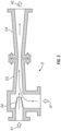
- FIG. 2 An example jet pump D, such as may be used for the first jet pump (40 in FIG. 1 ) and the second jet pump (40A in FIG. 1 ) is shown in more detail in FIG. 2 .
- the jet pump D may comprise a diffuser having a converging inlet diffuser D3 and a diverging outlet diffuser D4. An outlet of the converging outlet diffuser D4 may be coupled through a return line to the mud system (110 in FIG. 1 ).
- a working fluid inlet 41 to the jet pump D may be in fluid communication with the wellbore fluid outlet (e.g., through a check or non-return valve 44 in FIG. 1 ). Power or motive fluid may enter the jet pump D through a power fluid inlet.
- the power fluid may be supplied by pump 24 in FIG.
- the power fluid is discharged in the interior of the ejector assembly D upstream of the converging diffuser D3 through a nozzle D2.
- the nozzle D2 serves to increase velocity of the power fluid so as to reduce fluid pressure at the working fluid inlet D1.
- a combination of the power fluid and the working fluid e.g., the drilling fluid, maybe returned to the drilling platform (100 in FIG. 1 ) through a fluid return line.
- the pressure at a diffuser outlet 43 is related to the discharge static head and the discharge friction head.
- the discharge static head is related to fluid density.
- the fluid density can be reduced, for example, by injecting lower density fluids or gases into the fluid present at the discharge 43. If a gas, such as nitrogen, is injected into the discharge line (e.g., 13 in FIG. 1 ) the operating point of the jet pump will be changed.
- a gas such as nitrogen
- Managed pressure drilling systems and methods known in the art such as are disclosed in International Application Publication No. WO 2016/134442 filed by Reitsma et al. include using a jet pump for controlling the level of mud in a drilling riser.
- the foregoing application publication does not disclose an apparatus or method for handling large drill cuttings and/or high volume of drill cuttings.
- Large drill cuttings can introduce operating difficulties in a jet pump as they rely on small nozzle and annular throat diameters (e.g., approximately 2.54 cm ⁇ 1 inch ⁇ for deep water drilling applications). It is likely that drill cuttings exceeding this size may be present during drilling operations; without an effective means of dealing with such drill cuttings the jet pump will fail in its purpose of controlling mud level in the riser.
- the present disclosure provides a system able to handle large cuttings through the use of the rock catcher and separator (23 in FIG. 1 ) on the inlet from the riser (12 in FIG. 1 ) into the working fluid inlet of the first jet pump (40 in FIG. 1 ).
- the performance of the first jet pump 40in improved by operating the second jet pump 40A such that the working fluid inlet of the second jet pump 40A is coupled to the working fluid outlet of the first jet pump 40.
- Having the second, gas-operated jet pump 40A coupled to the working fluid outlet of first jet pump 40 reduces back pressure at the working fluid outlet of the first jet pump 40. Reduced back pressure allows increased performance of the first jet pump 40 to be obtained utilizing the mud pump(s) 22 on the drilling vessel or platform 100.
- Adding additional mud pumps to a drilling vessel may be cost prohibitive, and by using jet pumps as explained herein, a MPD system may provide capability to obtain extra performance out of existing drilling vessel equipment.
- Sensors for measuring certain parameters may be in signal communication with a controller or processor 80.
- the processor 80 may be, for example, a microprocessor, microcontroller, programmable logic controller or any other device capable of controlling operation of one or more output devices in response to measurements made by one or more sensors.
- the sensors may comprise one or more pressure sensors 50 in fluid communication with the riser (12 in FIG. 1 ) to provide measurements related to pressure in the wellbore and fluid level in the riser.
- Flow and/or pump operating rate sensors 52 may be provided for the riser boost pump(s) (24 in FIG. 1 ), for the rig mud pump(s) (22 in FIG.
- the controller 80 may comprise programming and/or embedded instructions to control operation of the riser boost pump at 62, the riser fill pump at 64, the rig mud pump(s) at 66, the annular pressure control device at 70 and a control rate signal for the gas injection system at 72. Control of the foregoing components of the system may be performed according to various methods described below.
- Methods according to the present disclosure for operating a MPD system may comprise the following. Particular components of the drilling system referred to by number in the following description may be observed in FIG. 1 .
- Method 1 Maintaining constant bottom hole pressure (CBHP) during "drilling ahead" (lengthening the well 21) whether drilling over balanced, balanced or under balanced.
- CBHP constant bottom hole pressure
- Over balanced means the fluid pressure in the well exceeds fluid pressure of exposed formations penetrated by the well 21.
- Balanced means that the well fluid pressure is the same as the formation fluid pressure, and under balanced means that the well fluid pressure is less than the formation fluid pressure.
- Method 2 Maintaining constant bottom hole pressure (CBHP) and ECD during tool joint (drill string segment) connections.
- CBHP constant bottom hole pressure
- ECD ECD during tool joint (drill string segment) connections.
- CBHP constant bottom hole pressure
- ECD ECD during tool joint (drill string segment) connections.
- the entire drill string 10 may be removed from the well 21.
- the rig mud pump(s) 22 are switched off and hydraulic connection between the mud pump(s) 22 and the drill string 10 are temporarily broken.
- Method 3 Isolate the first jet pump during well control operations.
- isolation valves are provided around the first jet pump 40 as shown in FIG. 1 . Once the isolation valves are closed, the first jet pump 40 is isolated from the choke line 17, and the choke line 17 becomes available for well control operations.
- a valve on the inlet to the first jet pump 40 can be closed and an in line valve opened to make the kill line 48 available for well control operations.
- Method 4 Clear blockages and debris from the first jet pump.
- obstructions can be cleared by closing a jet pump outlet valve while continuing to pump fluid into the first jet pump 40 power fluid inlet. This action will cause reverse flow through the first jet pump 40 to remove any obstruction. Obstruction may be detected by flow measurement or by using pressure sensors in fluid communication with the working fluid inlet and the working fluid outlet of the first jet pump 40.
Landscapes
- Engineering & Computer Science (AREA)
- Life Sciences & Earth Sciences (AREA)
- Geology (AREA)
- Mining & Mineral Resources (AREA)
- Physics & Mathematics (AREA)
- Environmental & Geological Engineering (AREA)
- Fluid Mechanics (AREA)
- General Life Sciences & Earth Sciences (AREA)
- Geochemistry & Mineralogy (AREA)
- Geophysics (AREA)
- Mechanical Engineering (AREA)
- Earth Drilling (AREA)
Claims (12)
- Procédé de commande de pression dans un puits (21), comprenant :le pompage de fluide dans une colonne montante (12) s'étendant entre une cuve de forage (100) et une tête de puits (18) ; etle pompage de fluide hors de la colonne montante vers la cuve de forage en faisant fonctionner une première pompe à jet (40) disposée dans un conduit s'étendant de la colonne montante vers la cuve de forage,la fourniture d'une seconde pompe à jet (40a) comportant une entrée de fluide de travail en communication avec une sortie de fluide de travail de la première pompe à jet (40), et une sortie de fluide de travail en communication fluidique avec le conduit ;la fourniture de fluide d'alimentation à la première pompe à jet au moyen d'une pompe à fluide d'alimentation (24) en communication fluidique avec une entrée de fluide d'alimentation de la première pompe à jet (40) ;la fourniture de fluide d'alimentation à la seconde pompe à jet (40A) au moyen d'une source de gaz (120) en communication fluidique avec une entrée de fluide d'alimentation de la seconde pompe à jet (40A) ; etla commande de la source de gaz (120) et de la pompe à fluide d'alimentation (24) pour maintenir un niveau de fluide dans la colonne montante (12) au niveau d'une élévation sélectionnée.
- Procédé selon la revendication 1, comprenant en outre un réglage d'un dispositif (46) de commande de pression annulaire de type iris disposé dans la colonne montante (12) dans un espace annulaire entre la colonne montante et un train de tiges de forage (10) disposé dans la colonne montante pour augmenter une contre-pression sur le puits (21).
- Procédé selon la revendication 1, comprenant en outre l'ajustement d'un débit du gaz de pompage pour maintenir le niveau de liquide au niveau de l'élévation sélectionnée.
- Procédé selon la revendication 1, comprenant en outre l'induction d'un écoulement de fluide inverse dans la première pompe à jet (40) pour en éliminer des obstructions.
- Système de forage sous pression contrôlée, comprenant :une colonne montante (12) s'étendant d'un puits sous-marin (21) à une plate-forme (100) sur la surface d'un plan d'eau, la colonne montante comportant un orifice de fluide au niveau d'un emplacement sélectionné au-dessus du puits sous-marin et au-dessous de la surface, l'orifice de fluide étant en communication fluidique avec une entrée de fluide de travail d'une première pompe à jet (40),une seconde pompe à jet (40A) comportant une entrée de fluide en communication fluidique avec une sortie de fluide de la première pompe à jet, une sortie de la seconde pompe à jet en communication fluidique avec un système de traitement de fluide sur la plate-forme ;une pompe à fluide d'alimentation (24) disposée sur la plate-forme et en communication fluidique avec une entrée de fluide d'alimentation de la première pompe à jet ; etune source de gaz (120) disposée sur la plate-forme et en communication fluidique avec une entrée de fluide d'alimentation de la seconde pompe à jet, dans lequel la pompe de fluide d'alimentation et la source de gaz peuvent être commandées de sorte qu'un niveau de fluide dans la colonne montante est maintenu au niveau d'une élévation sélectionnée.
- Système selon la revendication 5, comprenant en outre un capteur de niveau de fluide dans la colonne montante (12).
- Système selon la revendication 6, dans lequel le capteur de niveau de fluide comprend un capteur de pression.
- Système selon la revendication 6, comprenant en outre un dispositif de commande (80) en communication de signal avec le capteur de niveau de fluide, le dispositif de commande fournissant une sortie de commande pour faire fonctionner la pompe à fluide d'alimentation (24) et la source de gaz (120) en réponse à des signaux provenant du capteur de niveau de fluide pour maintenir le niveau de fluide au niveau de l'élévation sélectionnée.
- Système selon la revendication 5, comprenant en outre une pompe de fluide de forage disposée sur la plate-forme (100) et raccordée au niveau d'une sortie à un train de tiges de forage (10) s'étendant dans la colonne montante.
- Système selon la revendication 5, comprenant en outre des vannes (42) raccordées à l'entrée de fluide d'alimentation, à l'entrée de fluide de travail et à la sortie de fluide de la première pompe à jet (40), les vannes servant à amener du fluide à s'écouler dans la sortie de fluide de la première pompe à jet, les vannes servant à contourner la première pompe à jet et les vannes servant à diriger un écoulement de fluide de l'orifice vers l'entrée de fluide de travail de la première pompe à jet et un écoulement de fluide de la sortie de fluide de la première pompe à jet vers l'entrée de fluide de travail de la seconde pompe à jet (40A).
- Système selon la revendication 5, comprenant en outre un collecteur et un séparateur de roche (23) disposés dans une conduite de fluide raccordant l'orifice et l'entrée de fluide de travail de la première pompe à jet (40).
- Système selon la revendication 5, comprenant en outre un dispositif (46) de commande annulaire servant à fermer un espace annulaire dans la colonne montante entre la colonne montante (12) et un train de tiges disposé dans la colonne montante, dans lequel la pompe à fluide d'alimentation (24) sert à maintenir une pression sélectionnée dans le puits sous-marin (21) lorsqu'une pompe à fluide de forage en communication de pression avec une tige disposée dans la colonne montante est désactivée.
Applications Claiming Priority (2)
| Application Number | Priority Date | Filing Date | Title |
|---|---|---|---|
| US201962790152P | 2019-01-09 | 2019-01-09 | |
| PCT/US2020/012964 WO2020146656A1 (fr) | 2019-01-09 | 2020-01-09 | Procédé et système de forage sous pression contrôlée |
Publications (3)
| Publication Number | Publication Date |
|---|---|
| EP3908731A1 EP3908731A1 (fr) | 2021-11-17 |
| EP3908731A4 EP3908731A4 (fr) | 2022-08-10 |
| EP3908731B1 true EP3908731B1 (fr) | 2025-04-02 |
Family
ID=71521117
Family Applications (1)
| Application Number | Title | Priority Date | Filing Date |
|---|---|---|---|
| EP20738099.9A Active EP3908731B1 (fr) | 2019-01-09 | 2020-01-09 | Procédé et système de forage sous pression contrôlée |
Country Status (5)
| Country | Link |
|---|---|
| US (1) | US11719055B2 (fr) |
| EP (1) | EP3908731B1 (fr) |
| AU (1) | AU2020207342B2 (fr) |
| BR (1) | BR112021010513A2 (fr) |
| WO (1) | WO2020146656A1 (fr) |
Families Citing this family (1)
| Publication number | Priority date | Publication date | Assignee | Title |
|---|---|---|---|---|
| US20260022633A1 (en) * | 2024-07-18 | 2026-01-22 | Weatherford Technology Holdings, Llc | Rcd seal and bearing condition |
Family Cites Families (24)
| Publication number | Priority date | Publication date | Assignee | Title |
|---|---|---|---|---|
| US4063602A (en) | 1975-08-13 | 1977-12-20 | Exxon Production Research Company | Drilling fluid diverter system |
| US4091881A (en) * | 1977-04-11 | 1978-05-30 | Exxon Production Research Company | Artificial lift system for marine drilling riser |
| US6904982B2 (en) | 1998-03-27 | 2005-06-14 | Hydril Company | Subsea mud pump and control system |
| US7270185B2 (en) * | 1998-07-15 | 2007-09-18 | Baker Hughes Incorporated | Drilling system and method for controlling equivalent circulating density during drilling of wellbores |
| EG22117A (en) * | 1999-06-03 | 2002-08-30 | Exxonmobil Upstream Res Co | Method and apparatus for controlling pressure and detecting well control problems during drilling of an offshore well using a gas-lifted riser |
| CA2461639C (fr) | 2001-09-10 | 2013-08-06 | Ocean Riser Systems As | Ensemble et procede permettant de regler des pressions de fond de trou lors de forages sous-marins en eaux profondes |
| US6966367B2 (en) * | 2002-01-08 | 2005-11-22 | Weatherford/Lamb, Inc. | Methods and apparatus for drilling with a multiphase pump |
| US8955619B2 (en) * | 2002-05-28 | 2015-02-17 | Weatherford/Lamb, Inc. | Managed pressure drilling |
| US7497667B2 (en) * | 2004-08-24 | 2009-03-03 | Latigo Pipe And Equipment, Inc. | Jet pump assembly |
| US20070235223A1 (en) | 2005-04-29 | 2007-10-11 | Tarr Brian A | Systems and methods for managing downhole pressure |
| EP3696373A1 (fr) | 2008-04-04 | 2020-08-19 | Enhanced Drilling AS | Systèmes et procédés de forage sous-marin |
| US8347983B2 (en) | 2009-07-31 | 2013-01-08 | Weatherford/Lamb, Inc. | Drilling with a high pressure rotating control device |
| BR112012011127B1 (pt) * | 2009-11-10 | 2019-09-03 | Enhanced Drilling As | sistema e método para o controle de poço durante a perfuração |
| GB2478119A (en) * | 2010-02-24 | 2011-08-31 | Managed Pressure Operations Llc | A drilling system having a riser closure mounted above a telescopic joint |
| US8403059B2 (en) * | 2010-05-12 | 2013-03-26 | Sunstone Technologies, Llc | External jet pump for dual gradient drilling |
| US8162063B2 (en) * | 2010-09-03 | 2012-04-24 | Stena Drilling Ltd. | Dual gradient drilling ship |
| US8783379B2 (en) * | 2011-08-03 | 2014-07-22 | Roger Sverre Stave | Fluid transfer device usable in managed pressure and dual-gradient drilling |
| WO2013123141A2 (fr) * | 2012-02-14 | 2013-08-22 | Chevron U.S.A. Inc. | Systèmes et procédés de gestion de pression dans un puits de forage |
| CN107076317A (zh) | 2014-09-30 | 2017-08-18 | 日本电产科宝株式会社 | 流量控制装置及车辆 |
| GB201503166D0 (en) * | 2015-02-25 | 2015-04-08 | Managed Pressure Operations | Riser assembly |
| US20180073314A1 (en) * | 2015-02-26 | 2018-03-15 | Donald G. Reitsma | Mud lift drilling system using ejector assembly in mud return line |
| BR112018011267B1 (pt) | 2015-12-03 | 2023-03-28 | Schlumberger Technology B.V. | Estrangulamento de orifício controlável montado em riser |
| US20180135368A1 (en) * | 2016-11-11 | 2018-05-17 | Sjö Drilling As | Fluid transfer device usable in managed pressure and dual gradient drilling |
| MX2019007618A (es) * | 2016-12-22 | 2019-12-05 | Schlumberger Technology Bv | Restricción anular por etapas para perforación a presión controlada. |
-
2020
- 2020-01-09 WO PCT/US2020/012964 patent/WO2020146656A1/fr not_active Ceased
- 2020-01-09 BR BR112021010513-1A patent/BR112021010513A2/pt not_active IP Right Cessation
- 2020-01-09 EP EP20738099.9A patent/EP3908731B1/fr active Active
- 2020-01-09 AU AU2020207342A patent/AU2020207342B2/en active Active
- 2020-01-09 US US17/413,542 patent/US11719055B2/en active Active
Also Published As
| Publication number | Publication date |
|---|---|
| WO2020146656A1 (fr) | 2020-07-16 |
| US20220010636A1 (en) | 2022-01-13 |
| AU2020207342B2 (en) | 2025-06-26 |
| BR112021010513A2 (pt) | 2021-08-24 |
| EP3908731A4 (fr) | 2022-08-10 |
| AU2020207342A1 (en) | 2021-06-17 |
| EP3908731A1 (fr) | 2021-11-17 |
| US11719055B2 (en) | 2023-08-08 |
| CA3121007A1 (fr) | 2020-07-16 |
Similar Documents
| Publication | Publication Date | Title |
|---|---|---|
| US11085255B2 (en) | System and methods for controlled mud cap drilling | |
| RU2586129C1 (ru) | Система и способ управления давлением в кольцевом пространстве ствола скважины с применением газлифта в линии возврата бурового раствора | |
| US8322439B2 (en) | Arrangement and method for regulating bottom hole pressures when drilling deepwater offshore wells | |
| NO320829B1 (no) | Undervanns bronnhull-boresystem for redusering av bunnhulltrykk | |
| RU2520201C1 (ru) | Способ поддержания давления в скважине | |
| CA2326129A1 (fr) | Systeme de forage en mer | |
| CA2326358A1 (fr) | Deflecteur sous-marin rotatif | |
| WO2012003101A2 (fr) | Système et procédé permettant de réguler la pression dans un puits de forage | |
| EP2576956B1 (fr) | Procédé pour évacuer une arrivée de fluide d'un puits de forage sous-marin sans fermer le puits de forage | |
| WO2017037422A1 (fr) | Procédé de commande d'un système de forage | |
| NO20110564A1 (no) | Apparat og fremgangsmate for konstruksjon av en undersjoisk bronn | |
| EP3908731B1 (fr) | Procédé et système de forage sous pression contrôlée | |
| US8783379B2 (en) | Fluid transfer device usable in managed pressure and dual-gradient drilling | |
| US20180073314A1 (en) | Mud lift drilling system using ejector assembly in mud return line | |
| CA3121007C (fr) | Procede et systeme de forage sous pression controlee |
Legal Events
| Date | Code | Title | Description |
|---|---|---|---|
| STAA | Information on the status of an ep patent application or granted ep patent |
Free format text: STATUS: THE INTERNATIONAL PUBLICATION HAS BEEN MADE |
|
| PUAI | Public reference made under article 153(3) epc to a published international application that has entered the european phase |
Free format text: ORIGINAL CODE: 0009012 |
|
| STAA | Information on the status of an ep patent application or granted ep patent |
Free format text: STATUS: REQUEST FOR EXAMINATION WAS MADE |
|
| 17P | Request for examination filed |
Effective date: 20210802 |
|
| AK | Designated contracting states |
Kind code of ref document: A1 Designated state(s): AL AT BE BG CH CY CZ DE DK EE ES FI FR GB GR HR HU IE IS IT LI LT LU LV MC MK MT NL NO PL PT RO RS SE SI SK SM TR |
|
| DAV | Request for validation of the european patent (deleted) | ||
| DAX | Request for extension of the european patent (deleted) | ||
| A4 | Supplementary search report drawn up and despatched |
Effective date: 20220707 |
|
| RIC1 | Information provided on ipc code assigned before grant |
Ipc: E21B 7/12 20060101ALI20220701BHEP Ipc: E21B 21/08 20060101AFI20220701BHEP |
|
| STAA | Information on the status of an ep patent application or granted ep patent |
Free format text: STATUS: EXAMINATION IS IN PROGRESS |
|
| 17Q | First examination report despatched |
Effective date: 20240219 |
|
| GRAP | Despatch of communication of intention to grant a patent |
Free format text: ORIGINAL CODE: EPIDOSNIGR1 |
|
| STAA | Information on the status of an ep patent application or granted ep patent |
Free format text: STATUS: GRANT OF PATENT IS INTENDED |
|
| INTG | Intention to grant announced |
Effective date: 20241022 |
|
| GRAS | Grant fee paid |
Free format text: ORIGINAL CODE: EPIDOSNIGR3 |
|
| GRAJ | Information related to disapproval of communication of intention to grant by the applicant or resumption of examination proceedings by the epo deleted |
Free format text: ORIGINAL CODE: EPIDOSDIGR1 |
|
| GRAL | Information related to payment of fee for publishing/printing deleted |
Free format text: ORIGINAL CODE: EPIDOSDIGR3 |
|
| STAA | Information on the status of an ep patent application or granted ep patent |
Free format text: STATUS: EXAMINATION IS IN PROGRESS |
|
| GRAP | Despatch of communication of intention to grant a patent |
Free format text: ORIGINAL CODE: EPIDOSNIGR1 |
|
| STAA | Information on the status of an ep patent application or granted ep patent |
Free format text: STATUS: GRANT OF PATENT IS INTENDED |
|
| GRAA | (expected) grant |
Free format text: ORIGINAL CODE: 0009210 |
|
| STAA | Information on the status of an ep patent application or granted ep patent |
Free format text: STATUS: THE PATENT HAS BEEN GRANTED |
|
| INTC | Intention to grant announced (deleted) | ||
| INTG | Intention to grant announced |
Effective date: 20250224 |
|
| AK | Designated contracting states |
Kind code of ref document: B1 Designated state(s): AL AT BE BG CH CY CZ DE DK EE ES FI FR GB GR HR HU IE IS IT LI LT LU LV MC MK MT NL NO PL PT RO RS SE SI SK SM TR |
|
| REG | Reference to a national code |
Ref country code: GB Ref legal event code: FG4D |
|
| REG | Reference to a national code |
Ref country code: CH Ref legal event code: EP |
|
| P01 | Opt-out of the competence of the unified patent court (upc) registered |
Free format text: CASE NUMBER: APP_12932/2025 Effective date: 20250314 |
|
| REG | Reference to a national code |
Ref country code: IE Ref legal event code: FG4D |
|
| REG | Reference to a national code |
Ref country code: DE Ref legal event code: R096 Ref document number: 602020048719 Country of ref document: DE |
|
| REG | Reference to a national code |
Ref country code: NL Ref legal event code: MP Effective date: 20250402 |
|
| PG25 | Lapsed in a contracting state [announced via postgrant information from national office to epo] |
Ref country code: NL Free format text: LAPSE BECAUSE OF FAILURE TO SUBMIT A TRANSLATION OF THE DESCRIPTION OR TO PAY THE FEE WITHIN THE PRESCRIBED TIME-LIMIT Effective date: 20250402 |
|
| REG | Reference to a national code |
Ref country code: AT Ref legal event code: MK05 Ref document number: 1781426 Country of ref document: AT Kind code of ref document: T Effective date: 20250402 |
|
| PG25 | Lapsed in a contracting state [announced via postgrant information from national office to epo] |
Ref country code: PT Free format text: LAPSE BECAUSE OF FAILURE TO SUBMIT A TRANSLATION OF THE DESCRIPTION OR TO PAY THE FEE WITHIN THE PRESCRIBED TIME-LIMIT Effective date: 20250804 Ref country code: ES Free format text: LAPSE BECAUSE OF FAILURE TO SUBMIT A TRANSLATION OF THE DESCRIPTION OR TO PAY THE FEE WITHIN THE PRESCRIBED TIME-LIMIT Effective date: 20250402 Ref country code: FI Free format text: LAPSE BECAUSE OF FAILURE TO SUBMIT A TRANSLATION OF THE DESCRIPTION OR TO PAY THE FEE WITHIN THE PRESCRIBED TIME-LIMIT Effective date: 20250402 |
|
| REG | Reference to a national code |
Ref country code: LT Ref legal event code: MG9D |
|
| PG25 | Lapsed in a contracting state [announced via postgrant information from national office to epo] |
Ref country code: GR Free format text: LAPSE BECAUSE OF FAILURE TO SUBMIT A TRANSLATION OF THE DESCRIPTION OR TO PAY THE FEE WITHIN THE PRESCRIBED TIME-LIMIT Effective date: 20250703 |
|
| PG25 | Lapsed in a contracting state [announced via postgrant information from national office to epo] |
Ref country code: PL Free format text: LAPSE BECAUSE OF FAILURE TO SUBMIT A TRANSLATION OF THE DESCRIPTION OR TO PAY THE FEE WITHIN THE PRESCRIBED TIME-LIMIT Effective date: 20250402 |
|
| PG25 | Lapsed in a contracting state [announced via postgrant information from national office to epo] |
Ref country code: BG Free format text: LAPSE BECAUSE OF FAILURE TO SUBMIT A TRANSLATION OF THE DESCRIPTION OR TO PAY THE FEE WITHIN THE PRESCRIBED TIME-LIMIT Effective date: 20250402 |
|
| PG25 | Lapsed in a contracting state [announced via postgrant information from national office to epo] |
Ref country code: HR Free format text: LAPSE BECAUSE OF FAILURE TO SUBMIT A TRANSLATION OF THE DESCRIPTION OR TO PAY THE FEE WITHIN THE PRESCRIBED TIME-LIMIT Effective date: 20250402 |
|
| PG25 | Lapsed in a contracting state [announced via postgrant information from national office to epo] |
Ref country code: AT Free format text: LAPSE BECAUSE OF FAILURE TO SUBMIT A TRANSLATION OF THE DESCRIPTION OR TO PAY THE FEE WITHIN THE PRESCRIBED TIME-LIMIT Effective date: 20250402 |
|
| PG25 | Lapsed in a contracting state [announced via postgrant information from national office to epo] |
Ref country code: RS Free format text: LAPSE BECAUSE OF FAILURE TO SUBMIT A TRANSLATION OF THE DESCRIPTION OR TO PAY THE FEE WITHIN THE PRESCRIBED TIME-LIMIT Effective date: 20250702 |
|
| PG25 | Lapsed in a contracting state [announced via postgrant information from national office to epo] |
Ref country code: IS Free format text: LAPSE BECAUSE OF FAILURE TO SUBMIT A TRANSLATION OF THE DESCRIPTION OR TO PAY THE FEE WITHIN THE PRESCRIBED TIME-LIMIT Effective date: 20250802 |
|
| PG25 | Lapsed in a contracting state [announced via postgrant information from national office to epo] |
Ref country code: LV Free format text: LAPSE BECAUSE OF FAILURE TO SUBMIT A TRANSLATION OF THE DESCRIPTION OR TO PAY THE FEE WITHIN THE PRESCRIBED TIME-LIMIT Effective date: 20250402 |
|
| REG | Reference to a national code |
Ref country code: DE Ref legal event code: R097 Ref document number: 602020048719 Country of ref document: DE |
|
| PG25 | Lapsed in a contracting state [announced via postgrant information from national office to epo] |
Ref country code: SM Free format text: LAPSE BECAUSE OF FAILURE TO SUBMIT A TRANSLATION OF THE DESCRIPTION OR TO PAY THE FEE WITHIN THE PRESCRIBED TIME-LIMIT Effective date: 20250402 Ref country code: DK Free format text: LAPSE BECAUSE OF FAILURE TO SUBMIT A TRANSLATION OF THE DESCRIPTION OR TO PAY THE FEE WITHIN THE PRESCRIBED TIME-LIMIT Effective date: 20250402 |
|
| PG25 | Lapsed in a contracting state [announced via postgrant information from national office to epo] |
Ref country code: CZ Free format text: LAPSE BECAUSE OF FAILURE TO SUBMIT A TRANSLATION OF THE DESCRIPTION OR TO PAY THE FEE WITHIN THE PRESCRIBED TIME-LIMIT Effective date: 20250402 |
|
| PG25 | Lapsed in a contracting state [announced via postgrant information from national office to epo] |
Ref country code: EE Free format text: LAPSE BECAUSE OF FAILURE TO SUBMIT A TRANSLATION OF THE DESCRIPTION OR TO PAY THE FEE WITHIN THE PRESCRIBED TIME-LIMIT Effective date: 20250402 |
|
| PG25 | Lapsed in a contracting state [announced via postgrant information from national office to epo] |
Ref country code: SK Free format text: LAPSE BECAUSE OF FAILURE TO SUBMIT A TRANSLATION OF THE DESCRIPTION OR TO PAY THE FEE WITHIN THE PRESCRIBED TIME-LIMIT Effective date: 20250402 Ref country code: RO Free format text: LAPSE BECAUSE OF FAILURE TO SUBMIT A TRANSLATION OF THE DESCRIPTION OR TO PAY THE FEE WITHIN THE PRESCRIBED TIME-LIMIT Effective date: 20250402 |
|
| PG25 | Lapsed in a contracting state [announced via postgrant information from national office to epo] |
Ref country code: IT Free format text: LAPSE BECAUSE OF FAILURE TO SUBMIT A TRANSLATION OF THE DESCRIPTION OR TO PAY THE FEE WITHIN THE PRESCRIBED TIME-LIMIT Effective date: 20250402 |
|
| PLBE | No opposition filed within time limit |
Free format text: ORIGINAL CODE: 0009261 |
|
| STAA | Information on the status of an ep patent application or granted ep patent |
Free format text: STATUS: NO OPPOSITION FILED WITHIN TIME LIMIT |
|
| REG | Reference to a national code |
Ref country code: CH Ref legal event code: L10 Free format text: ST27 STATUS EVENT CODE: U-0-0-L10-L00 (AS PROVIDED BY THE NATIONAL OFFICE) Effective date: 20260211 |
|
| 26N | No opposition filed |
Effective date: 20260105 |
|
| PGFP | Annual fee paid to national office [announced via postgrant information from national office to epo] |
Ref country code: NO Payment date: 20260126 Year of fee payment: 7 |