EP3908765B1 - Arrangement actionneur pour un arrangement d'accouplement pour une chaîne cinématique d'un véhicule automobile - Google Patents
Arrangement actionneur pour un arrangement d'accouplement pour une chaîne cinématique d'un véhicule automobile Download PDFInfo
- Publication number
- EP3908765B1 EP3908765B1 EP19701455.8A EP19701455A EP3908765B1 EP 3908765 B1 EP3908765 B1 EP 3908765B1 EP 19701455 A EP19701455 A EP 19701455A EP 3908765 B1 EP3908765 B1 EP 3908765B1
- Authority
- EP
- European Patent Office
- Prior art keywords
- ring
- clutch
- ramp
- gear
- ramp ring
- Prior art date
- Legal status (The legal status is an assumption and is not a legal conclusion. Google has not performed a legal analysis and makes no representation as to the accuracy of the status listed.)
- Active
Links
Images


Classifications
-
- F—MECHANICAL ENGINEERING; LIGHTING; HEATING; WEAPONS; BLASTING
- F16—ENGINEERING ELEMENTS AND UNITS; GENERAL MEASURES FOR PRODUCING AND MAINTAINING EFFECTIVE FUNCTIONING OF MACHINES OR INSTALLATIONS; THERMAL INSULATION IN GENERAL
- F16D—COUPLINGS FOR TRANSMITTING ROTATION; CLUTCHES; BRAKES
- F16D23/00—Details of mechanically-actuated clutches not specific for one distinct type
- F16D23/12—Mechanical clutch-actuating mechanisms arranged outside the clutch as such
-
- F—MECHANICAL ENGINEERING; LIGHTING; HEATING; WEAPONS; BLASTING
- F16—ENGINEERING ELEMENTS AND UNITS; GENERAL MEASURES FOR PRODUCING AND MAINTAINING EFFECTIVE FUNCTIONING OF MACHINES OR INSTALLATIONS; THERMAL INSULATION IN GENERAL
- F16D—COUPLINGS FOR TRANSMITTING ROTATION; CLUTCHES; BRAKES
- F16D13/00—Friction clutches
- F16D13/22—Friction clutches with axially-movable clutching members
- F16D13/38—Friction clutches with axially-movable clutching members with flat clutching surfaces, e.g. discs
- F16D13/52—Clutches with multiple lamellae ; Clutches in which three or more axially moveable members are fixed alternately to the shafts to be coupled and are pressed from one side towards an axially-located member
-
- F—MECHANICAL ENGINEERING; LIGHTING; HEATING; WEAPONS; BLASTING
- F16—ENGINEERING ELEMENTS AND UNITS; GENERAL MEASURES FOR PRODUCING AND MAINTAINING EFFECTIVE FUNCTIONING OF MACHINES OR INSTALLATIONS; THERMAL INSULATION IN GENERAL
- F16D—COUPLINGS FOR TRANSMITTING ROTATION; CLUTCHES; BRAKES
- F16D21/00—Systems comprising a plurality of actuated clutches
-
- F—MECHANICAL ENGINEERING; LIGHTING; HEATING; WEAPONS; BLASTING
- F16—ENGINEERING ELEMENTS AND UNITS; GENERAL MEASURES FOR PRODUCING AND MAINTAINING EFFECTIVE FUNCTIONING OF MACHINES OR INSTALLATIONS; THERMAL INSULATION IN GENERAL
- F16D—COUPLINGS FOR TRANSMITTING ROTATION; CLUTCHES; BRAKES
- F16D23/00—Details of mechanically-actuated clutches not specific for one distinct type
- F16D23/12—Mechanical clutch-actuating mechanisms arranged outside the clutch as such
- F16D23/14—Clutch-actuating sleeves or bearings; Actuating members directly connected to clutch-actuating sleeves or bearings
-
- F—MECHANICAL ENGINEERING; LIGHTING; HEATING; WEAPONS; BLASTING
- F16—ENGINEERING ELEMENTS AND UNITS; GENERAL MEASURES FOR PRODUCING AND MAINTAINING EFFECTIVE FUNCTIONING OF MACHINES OR INSTALLATIONS; THERMAL INSULATION IN GENERAL
- F16D—COUPLINGS FOR TRANSMITTING ROTATION; CLUTCHES; BRAKES
- F16D28/00—Electrically-actuated clutches
-
- F—MECHANICAL ENGINEERING; LIGHTING; HEATING; WEAPONS; BLASTING
- F16—ENGINEERING ELEMENTS AND UNITS; GENERAL MEASURES FOR PRODUCING AND MAINTAINING EFFECTIVE FUNCTIONING OF MACHINES OR INSTALLATIONS; THERMAL INSULATION IN GENERAL
- F16H—GEARING
- F16H37/00—Combinations of mechanical gearings, not provided for in groups F16H1/00 - F16H35/00
- F16H37/02—Combinations of mechanical gearings, not provided for in groups F16H1/00 - F16H35/00 comprising essentially only toothed or friction gearings
- F16H37/06—Combinations of mechanical gearings, not provided for in groups F16H1/00 - F16H35/00 comprising essentially only toothed or friction gearings with a plurality of driving or driven shafts; with arrangements for dividing torque between two or more intermediate shafts
- F16H37/08—Combinations of mechanical gearings, not provided for in groups F16H1/00 - F16H35/00 comprising essentially only toothed or friction gearings with a plurality of driving or driven shafts; with arrangements for dividing torque between two or more intermediate shafts with differential gearing
- F16H37/0806—Combinations of mechanical gearings, not provided for in groups F16H1/00 - F16H35/00 comprising essentially only toothed or friction gearings with a plurality of driving or driven shafts; with arrangements for dividing torque between two or more intermediate shafts with differential gearing with a plurality of driving or driven shafts
- F16H37/0813—Combinations of mechanical gearings, not provided for in groups F16H1/00 - F16H35/00 comprising essentially only toothed or friction gearings with a plurality of driving or driven shafts; with arrangements for dividing torque between two or more intermediate shafts with differential gearing with a plurality of driving or driven shafts with only one input shaft
- F16H37/082—Combinations of mechanical gearings, not provided for in groups F16H1/00 - F16H35/00 comprising essentially only toothed or friction gearings with a plurality of driving or driven shafts; with arrangements for dividing torque between two or more intermediate shafts with differential gearing with a plurality of driving or driven shafts with only one input shaft and additional planetary reduction gears
-
- B—PERFORMING OPERATIONS; TRANSPORTING
- B60—VEHICLES IN GENERAL
- B60K—ARRANGEMENT OR MOUNTING OF PROPULSION UNITS OR OF TRANSMISSIONS IN VEHICLES; ARRANGEMENT OR MOUNTING OF PLURAL DIVERSE PRIME-MOVERS IN VEHICLES; AUXILIARY DRIVES FOR VEHICLES; INSTRUMENTATION OR DASHBOARDS FOR VEHICLES; ARRANGEMENTS IN CONNECTION WITH COOLING, AIR INTAKE, GAS EXHAUST OR FUEL SUPPLY OF PROPULSION UNITS IN VEHICLES
- B60K1/00—Arrangement or mounting of electrical propulsion units
- B60K2001/001—Arrangement or mounting of electrical propulsion units one motor mounted on a propulsion axle for rotating right and left wheels of this axle
-
- F—MECHANICAL ENGINEERING; LIGHTING; HEATING; WEAPONS; BLASTING
- F16—ENGINEERING ELEMENTS AND UNITS; GENERAL MEASURES FOR PRODUCING AND MAINTAINING EFFECTIVE FUNCTIONING OF MACHINES OR INSTALLATIONS; THERMAL INSULATION IN GENERAL
- F16D—COUPLINGS FOR TRANSMITTING ROTATION; CLUTCHES; BRAKES
- F16D23/00—Details of mechanically-actuated clutches not specific for one distinct type
- F16D23/12—Mechanical clutch-actuating mechanisms arranged outside the clutch as such
- F16D2023/123—Clutch actuation by cams, ramps or ball-screw mechanisms
-
- F—MECHANICAL ENGINEERING; LIGHTING; HEATING; WEAPONS; BLASTING
- F16—ENGINEERING ELEMENTS AND UNITS; GENERAL MEASURES FOR PRODUCING AND MAINTAINING EFFECTIVE FUNCTIONING OF MACHINES OR INSTALLATIONS; THERMAL INSULATION IN GENERAL
- F16H—GEARING
- F16H2200/00—Transmissions for multiple ratios
- F16H2200/0021—Transmissions for multiple ratios specially adapted for electric vehicles
-
- F—MECHANICAL ENGINEERING; LIGHTING; HEATING; WEAPONS; BLASTING
- F16—ENGINEERING ELEMENTS AND UNITS; GENERAL MEASURES FOR PRODUCING AND MAINTAINING EFFECTIVE FUNCTIONING OF MACHINES OR INSTALLATIONS; THERMAL INSULATION IN GENERAL
- F16H—GEARING
- F16H2200/00—Transmissions for multiple ratios
- F16H2200/003—Transmissions for multiple ratios characterised by the number of forward speeds
- F16H2200/0034—Transmissions for multiple ratios characterised by the number of forward speeds the gear ratios comprising two forward speeds
-
- F—MECHANICAL ENGINEERING; LIGHTING; HEATING; WEAPONS; BLASTING
- F16—ENGINEERING ELEMENTS AND UNITS; GENERAL MEASURES FOR PRODUCING AND MAINTAINING EFFECTIVE FUNCTIONING OF MACHINES OR INSTALLATIONS; THERMAL INSULATION IN GENERAL
- F16H—GEARING
- F16H2200/00—Transmissions for multiple ratios
- F16H2200/20—Transmissions using gears with orbital motion
- F16H2200/2002—Transmissions using gears with orbital motion characterised by the number of sets of orbital gears
- F16H2200/2005—Transmissions using gears with orbital motion characterised by the number of sets of orbital gears with one sets of orbital gears
-
- F—MECHANICAL ENGINEERING; LIGHTING; HEATING; WEAPONS; BLASTING
- F16—ENGINEERING ELEMENTS AND UNITS; GENERAL MEASURES FOR PRODUCING AND MAINTAINING EFFECTIVE FUNCTIONING OF MACHINES OR INSTALLATIONS; THERMAL INSULATION IN GENERAL
- F16H—GEARING
- F16H2200/00—Transmissions for multiple ratios
- F16H2200/20—Transmissions using gears with orbital motion
- F16H2200/203—Transmissions using gears with orbital motion characterised by the engaging friction means not of the freewheel type, e.g. friction clutches or brakes
- F16H2200/2035—Transmissions using gears with orbital motion characterised by the engaging friction means not of the freewheel type, e.g. friction clutches or brakes with two engaging means
-
- F—MECHANICAL ENGINEERING; LIGHTING; HEATING; WEAPONS; BLASTING
- F16—ENGINEERING ELEMENTS AND UNITS; GENERAL MEASURES FOR PRODUCING AND MAINTAINING EFFECTIVE FUNCTIONING OF MACHINES OR INSTALLATIONS; THERMAL INSULATION IN GENERAL
- F16H—GEARING
- F16H2200/00—Transmissions for multiple ratios
- F16H2200/20—Transmissions using gears with orbital motion
- F16H2200/203—Transmissions using gears with orbital motion characterised by the engaging friction means not of the freewheel type, e.g. friction clutches or brakes
- F16H2200/2064—Transmissions using gears with orbital motion characterised by the engaging friction means not of the freewheel type, e.g. friction clutches or brakes using at least one positive clutch, e.g. dog clutch
-
- F—MECHANICAL ENGINEERING; LIGHTING; HEATING; WEAPONS; BLASTING
- F16—ENGINEERING ELEMENTS AND UNITS; GENERAL MEASURES FOR PRODUCING AND MAINTAINING EFFECTIVE FUNCTIONING OF MACHINES OR INSTALLATIONS; THERMAL INSULATION IN GENERAL
- F16H—GEARING
- F16H2200/00—Transmissions for multiple ratios
- F16H2200/20—Transmissions using gears with orbital motion
- F16H2200/2094—Transmissions using gears with orbital motion using positive clutches, e.g. dog clutches
-
- F—MECHANICAL ENGINEERING; LIGHTING; HEATING; WEAPONS; BLASTING
- F16—ENGINEERING ELEMENTS AND UNITS; GENERAL MEASURES FOR PRODUCING AND MAINTAINING EFFECTIVE FUNCTIONING OF MACHINES OR INSTALLATIONS; THERMAL INSULATION IN GENERAL
- F16H—GEARING
- F16H2702/00—Combinations of two or more transmissions
- F16H2702/02—Mechanical transmissions with planetary gearing combined with one or more other mechanical transmissions
Definitions
- the invention relates to an actuator arrangement for a drive train of a motor vehicle.
- the invention further relates to a clutch arrangement with such an actuator arrangement and a corresponding drive arrangement for driving a motor vehicle with such an actuator arrangement.
- actuators are used for a variety of functional units in motor vehicle drive trains.
- actuators are known for clutches that are used in motor vehicle drive trains to selectively establish, interrupt or set a torque transmission to a desired value.
- Multi-axle driven motor vehicles with a first drive train for permanently driving a first drive axle and a second drive train for optionally driving a second drive axle are known.
- Different drive concepts are distinguished here, for example motor vehicles with a front engine in which the front axle is permanently driven and the rear axle can be switched on.
- motor vehicles with a rear engine are known in which the rear axle is permanently driven and the front axle is switched on as required.
- the switchable drive axle can be driven by an electric motor, for example.
- a clutch arrangement for a drive train of a motor vehicle comprises a clutch which can drive-connect or disconnect two shafts, a Brake for braking the second shaft and an actuating device for actuating the clutch and the brake.
- the actuating device has a ramp mechanism with a first ring which is axially supported relative to the stationary component and a second ring which is axially displaceable relative to the first ring when one of the rings is rotated relative to the other.
- a clutch device with a roller one-way clutch and a cam clutch is known.
- the roller one-way clutch is designed in such a way that the rotary movement of an inner race of the clutch is enabled in one direction and blocked in the other direction.
- the cam clutch acts as a brake, which can block the rotary movement of the inner race in both directions.
- the cam clutch comprises an axially movable working ring with axial pins that can be brought into positive engagement with corresponding recesses in the inner race.
- a drive arrangement for a multi-axle driven motor vehicle comprises a differential unit, a controllable clutch for driving connection to a drive unit and a locking clutch for locking the compensating movement of the differential.
- the two clutches are arranged coaxially to one another and can be actuated by means of a ball ramp arrangement.
- the locking clutch is actuated first and then the engagement clutch.
- the engagement clutch is actuated first and then the locking clutch.
- Actuators for parking locks are known which are used in the drive trains of motor vehicles to optionally block a drive component in the drive train so that the motor vehicle is prevented from unintentionally rolling away if the drive source does not provide any torque.
- a drive unit for a motor vehicle is known, with an electric motor, a change gear with at least two gears and a differential.
- an actuator arrangement is provided which has a rotary-driven shift drum.
- the shift drum is used to actuate a shift sleeve which actuates a first shift clutch or alternatively a second shift clutch.
- a parking lock device is also provided which is arranged coaxially to the motor shaft.
- the parking lock device has a locking sleeve which is mounted so as to be axially displaceable between a release position and a locking position.
- the locking sleeve can be actuated by means of the same actuator arrangement as the shift clutches.
- a further object is to propose a clutch arrangement or drive arrangement with such an actuator arrangement.
- an actuator arrangement for a clutch arrangement in the drive train of a motor vehicle comprising: a rotationally drivable drive wheel; a locking ring which is mounted in a stationary housing so as to be rotatable about an axis of rotation and which is drive-connected to the drive wheel via a power path, wherein the locking ring can be rotated by the drive wheel from a first rotational position against a rotational stop into a second rotational position; wherein at least one friction surface pairing is provided in the power path between the drive wheel and the locking ring, via which a torque can be transmitted to the locking ring using frictional forces; a first ramp ring and a second ramp ring which can be driven in rotation by the drive wheel, wherein the first ramp ring and the second ramp ring are axially supported against one another and are designed to convert a relative rotational movement into an axial movement; wherein the ramp ring can continue to be driven in rotation by the drive wheel after the locking ring has reached the rotational stop.
- the actuator arrangement can implement two functions, namely the actuation of the locking ring, for example for a freewheel clutch, and the actuation of another actuating element, for example for a friction clutch.
- the proposed actuator arrangement therefore only requires a small number of components, which has a positive effect on the required installation space and the manufacturing and assembly costs.
- electrical integration is also achieved, which also has a positive effect on the reliability and service life of the arrangement due to a smaller number of electrical interfaces.
- the locking ring can have a ring section and at least one connecting element protruding therefrom for introducing a torque into the locking ring.
- the locking ring can be mounted in the stationary housing with the ring section so that it can rotate to a limited extent.
- One, two, three or more connecting elements can be provided, which are in particular evenly distributed over the circumference and can protrude radially outwards from the ring section. It is understood that if reference is made here to one or at least one connecting section, the features described can also apply to any other connecting section.
- the stationary housing can have a sleeve-shaped section in which the locking ring is mounted so as to be rotatable about the axis of rotation, wherein the sleeve-shaped section has at least one radial opening into which the at least one connecting element of the locking ring engages.
- one opening is provided for each connecting element.
- the at least one connecting element is resiliently loaded against an actuating ring that can be driven by the drive wheel and is in frictional contact with the latter.
- the actuating ring can be rotated relative to the locking ring, whereby by rotating the actuating ring the locking ring is driven along due to the friction effect until the locking ring comes into contact with a rotation stop. After the locking ring stops rotating, the actuating ring continues to rotate, whereby the at least one connecting element slides along the contact surface of the actuating ring.
- the at least one connecting element can be resiliently supported against a base body of the locking ring via a spring element.
- the base body of the locking ring is in particular ring-shaped and preferably has several radial bores distributed over the circumference, in each of which a connecting element is seated with resilient support.
- a connecting element and associated spring element can be designed as separate elements, whereby it is also possible for them to be firmly connected to one another and/or designed as a single piece.
- the actuating ring with which the locking ring is in frictional contact via the connecting elements, can in principle be any component in the power path between the drive wheel and the locking ring.
- the actuating ring can be connected in a rotationally fixed manner to the first ramp ring that can be driven in rotation, in particular can be designed as a single piece with it.
- the friction surface pairing for driving the locking ring in rotation is formed between a contact surface of a connecting element and a contact surface of the first ramp ring.
- the actuating ring can be designed in the form of an intermediate wheel that can be driven in rotation about the axis of rotation by the drive wheel.
- the friction surface pairing is formed between a contact surface of a connecting element and a contact surface of the intermediate wheel.
- the drive wheel can a first toothing for driving the first ramp ring and a second toothing for driving the intermediate gear, wherein the two toothings have a different diameter or a different number of teeth.
- the locking element can be connected to the second ramp ring in a rotationally fixed manner via the at least one connecting element, so that both rotate together.
- the friction surface pairing is formed in the power path between the first ramp ring, which can be driven in rotation, and the second ramp ring.
- the first ramp ring and the second ramp ring are axially supported against each other indirectly via balls that run in corresponding ball grooves of the first and second ramp rings.
- the ball grooves can be designed in such a way that they each have a decreasing depth in the same circumferential direction when viewed from above onto the end faces, with a ball being accommodated in pairs of opposing ball grooves, via which the first and second rings support each other.
- the balls move into deeper or shallower groove areas, depending on the direction of rotation, so that the two ramp rings either axially approach each other or move away from each other.
- the first ramp ring and the second ramp ring can also be axially supported directly against each other via corresponding sliding surfaces.
- the second ramp ring is axially supported against the stationary housing, wherein the first ramp ring is driven by rotation by means of the drive wheel from a first axial position, in which the first ramp ring is axially approached to the second ramp ring, into a second axial position, in in which the first ramp ring is axially spaced from the second ramp ring.
- the first ramp ring can have an actuating surface for axially loading a friction clutch on its side facing away from the second ramp ring.
- a clutch arrangement with an actuator arrangement which is designed according to at least one of the above-mentioned embodiments, comprising: a positive-locking clutch with a first clutch element and a second clutch element which can be moved axially thereto, wherein the second clutch element is connected to the first clutch element in a closed position in a rotationally fixed manner and is decoupled from the first clutch element in an open position in order to be freely rotatable relative to it; a friction clutch for variable torque transmission between a first clutch part and a second clutch part; wherein the locking ring of the actuator arrangement blocks an axial movement of the second clutch element of the positive-locking clutch in the first rotational position, wherein the positive-locking clutch is closed; wherein the locking ring, by rotating into the second rotational position by means of the drive wheel, axially releases the second clutch element of the positive-locking clutch so that the positive-locking clutch is opened; When the drive wheel is rotated further, the locking ring remains in the second rotational position and the friction
- the first coupling element of the form-locking coupling can be supported in the direction of rotation in the stationary housing and can be moved axially.
- the first coupling element of the form-locking coupling can also be referred to as an adjusting element or blocking element, and the form-locking coupling can also be referred to as a freewheel clutch.
- the second coupling element of the form-locking coupling can be connected to a shaft in a rotationally fixed and axially fixed manner.
- the friction clutch can have first plates connected to the first friction clutch part in a rotationally fixed and axially movable manner and second plates connected to the second friction clutch part in a rotationally fixed and axially movable manner, wherein the first and second lamellae are arranged in particular axially alternately and together form a lamella pack.
- the lamella pack can be axially loaded by a pressure plate which can be actuated by the first ramp ring, wherein an axial bearing for rotational decoupling is provided between the first ramp ring and the pressure plate.
- a planetary gear transmission can be provided with a transmission input part and an input gear that can be driven by the electric machine to rotate about an axis of rotation (A), a support wheel that is arranged to rotate coaxially with the input gear and that is connected in a rotationally fixed manner to the support element of the positive locking clutch, wherein the support wheel is supported in the direction of rotation on the stationary component in the closed position of the positive locking clutch and is freely rotatable in an open position of the positive locking clutch, a plurality of planet gears that are in toothed engagement with the input gear and the support wheel, and a carrier element on which the planet gears are rotatably mounted and which can be driven to rotate about the axis of rotation in order to transmit torque to a downstream drive unit, wherein the friction clutch is arranged in the power path between one of the parts input gear, support wheel and carrier element and another of the parts input gear, support wheel and carrier element.
- a first transmission ratio is formed between the drive wheel and the carrier element
- a variable torque can be transmitted between the drive wheel and the carrier element by means of the friction clutch, wherein when the friction clutch is completely closed, a second transmission ratio is formed between the drive wheel and the carrier element.
- the carrier element of the epicyclic gear can be connected to a downstream power split unit, which can be designed in the form of a differential gear, for example.
- the differential gear divides the introduced rotary motion into two output parts to drive a respective side shaft.
- a dual clutch unit can also be used as a power split unit (twin clutch).
- the Figures 1 to 3 are described together below.
- An actuator arrangement 2 according to the invention for actuating clutches in the drive train of a motor vehicle is shown.
- the actuator arrangement 2 comprises a drive wheel 3 which can be driven by an actuator drive unit (not shown), a ramp ring arrangement 4 which is designed to convert a rotary movement initiated by the drive wheel 3 into an axial movement, and a locking ring 5 which is indirectly drive-connected to the drive wheel 3 in order to be rotated by it about the axis of rotation A.
- the ramp ring arrangement 4 is designed in the form of a ball ramp unit, which has a first ramp ring 6 with several circumferentially distributed first ball tracks 7, a second ramp ring 8 with several circumferentially distributed second ball tracks 9 and several circumferentially distributed balls, each of which is arranged between a first ball track 7 and a second ball track 9 and is guided in them.
- the balls lie outside the shown cutting plane and are therefore not shown.
- the actuator drive wheel 3 is drive-connected to the first ramp ring 6 in order to rotate it about the axis of rotation A.
- the drive wheel 3 has a first toothing 12 for initiating a rotary movement from a drive source and a second toothing 13 which engages with a counter toothing 14 of the first ramp ring 6.
- the second ramp ring 8 is axially supported against a stationary component 16 and held in a rotationally fixed manner.
- the stationary component 16 is designed as a sleeve-shaped section of a housing 17. Due to a relative rotational movement of the first ramp ring 6 with respect to the rotationally fixed second ramp ring 8, the balls run in the ball grooves 7, 9 in the circumferential direction, whereby - when the balls move into flatter sections the ball grooves 7, 9 - the first ramp ring 6 is moved axially away from the second ramp ring 8.
- the locking ring 5 has several connecting elements 18 distributed over the circumference, which are in frictional contact with an inner circumferential surface 19 of an actuating ring 59 of the first ramp ring 6.
- the actuating ring 59 is designed with the ramp ring 6.
- exactly three connecting elements 18 are provided, distributed regularly over the circumference, although a different number is also possible.
- the connecting elements 18 extend radially outward through circumferentially distributed openings 20 of the stationary component 16.
- the openings 20 have a circumferential extent ⁇ 20 that is greater than a circumferential extent ⁇ 22 of the connecting elements 18 or the support elements 22 in which the connecting elements 18 are received, so that the locking ring 5 can be rotated to a limited extent relative to the stationary component 16.
- the side walls 23, 24 of the openings 20 form rotation stops against which the support elements 22 can rest in the circumferential direction. It is particularly important in the lower half of the cut of Figure 1A It can be seen that the openings 20 are designed in the form of slots which extend from a free end 29 of the sleeve-shaped housing part 16 to an axial stop 33 against which the locking ring 5 is axially supported.
- the connecting elements 18 are each resiliently supported in the radial direction against the respective support element 22 via a spring element 25.
- the spring preload brings the connecting elements 18 into frictional contact with the inner surface 19 of the first ring 6, so that when the first ring 6 rotates, they rotate with it until they come into contact with one or the other rotation stop 23, 24, depending on the direction of rotation. After reaching the rotation stop, the first ring 6 continues to rotate, but the adjusting ring 5 remains in its rotational position and the connecting elements 18 slide along the inner surface 19 of the first ring 6.
- the locking ring 5 also has a ring section 15 with an internal toothing 26. Axially adjacent to the locking ring, a second sleeve-shaped housing part 27 is provided which is connected to the sleeve-shaped housing part 16. The second sleeve-shaped Housing part 27 has a second internal toothing 28, which is designed in the same way as the internal toothing 26 of the locking ring 5.
- the locking ring 5 By rotating the ramp ring 6, the locking ring 5 is rotated by a limited rotational path via the connecting elements 18.
- the locking ring 5 is moved from the first rotational position Pr1, in which its internal toothing 26 is offset in the circumferential direction relative to the internal toothing 28 of the housing part 27 (tooth-on-gap position), to a second rotational position Pr2, in which the two internal toothings 26, 28 are aligned with one another (tooth-on-tooth position).
- the teeth of the locking ring 5 In the first rotational position Pr1, at least some of the teeth of the locking ring 5 are located in circumferential areas of tooth gaps of the housing part 27, so that an axial movement of a component 32 in tooth engagement with the housing part 27 is blocked by the locking ring 5.
- the toothing 26 of the locking ring 5 forms a natural continuation of the toothing 28 of the housing part 27, so that the component 32, which engages with its corresponding external toothing in the internal toothing 28 of the housing part 27, can now be displaced axially into the internal toothing 26 of the locking ring 5.
- the ball ramp arrangement 4 is designed in particular such that the adjusting ring 6 maintains its axial position Pa1 when rotated relative to the support ring 8 in the direction R1 until the locking ring 5 has reached its end stop 24 (second rotational position Pr2). Only after the adjusting ring 5 has assumed its second rotational position Pr2 and the component 32 engages in the toothing 26 of the locking ring 5 do the balls of the ball ramp arrangement 4 move into flatter areas, so that the adjusting ring 6 is moved axially away from the support ring 8 in the direction of a second axial position Pa2.
- the actuator arrangement 2 can thus realize two functions, namely the actuation of the locking ring 5 in order to selectively block or release an axial movement of the component 32, as well as the actuation of a further actuating member 49 by means of the axially movable adjusting ring 6.
- the Figures 2A to 2C show a clutch arrangement 11 according to the invention with an actuator arrangement 2 according to the invention according to Figure 1 .
- the clutch arrangement 11 comprises a first clutch 30, which is designed in the form of a positive-locking clutch, and a second clutch 40, which is designed in the form of a friction clutch.
- the form-fitting coupling 30 comprises a first coupling part 31, which is connected to a shaft 34 in a rotationally fixed manner, and the component 32 as a second coupling part.
- the first coupling part is axially supported with an end section against a shaft shoulder of the shaft 34.
- the shaft 34 with the first coupling part 31 attached thereto is mounted in the housing part 16 so that it can rotate about the axis of rotation A and is axially supported by means of a bearing 35.
- An inner bearing ring of the bearing 35 is axially supported between a shoulder of the coupling part 31 and an axial locking ring.
- the outer bearing ring is accommodated in the housing part 16 and axially supported by means of a further axial locking ring.
- the second coupling part 32 has an external toothing 36 which is in toothed engagement with the internal toothing 28 of the housing part 16 for transmitting or supporting a torque, wherein the second coupling part 32 is axially movable relative to the housing part 16.
- the Figure 2B shows the positive-locking coupling 30 in the closed position, in which the first coupling part 31 and the second coupling part 32 are in positive engagement with one another.
- the shaft 34 is supported in the direction of rotation on the housing part 16 via the first coupling part 31 and the second coupling part 32 which is in engagement with it.
- the locking ring 5 is moved by rotating the ramp ring 6 from the first rotational position Pr1, in which the locking ring internal toothing 26 is offset in the direction of rotation relative to the housing internal toothing 28, to the second rotational position Pr2, in which the two internal toothings 26, 28 are aligned with one another.
- the axial blocking of the clutch part 32 is removed, which can now be moved axially into the locking ring 5 beyond the axial end of the housing internal toothing 28.
- the axial force for moving the coupling part 32 is caused by the fact that the internal toothing 28 of the housing part 16 and the corresponding external toothing 36 are designed as helical gears.
- the helical gears are designed in such a way that a torque introduced into the shaft 34 and correspondingly effective between the first coupling part 31 and the second coupling part 32 causes an axial movement of the second coupling part 32 in the opening direction.
- the second clutch 40 is designed as a friction clutch, which comprises a first clutch part 41 and a second clutch part 42 that can be connected to it for variable torque transmission.
- the first clutch part 41 forms a first disk carrier 43, to which first disks 44 are connected in a rotationally fixed and axially movable manner.
- the second clutch part 42 forms a second disk carrier 45, to which second disks 46 are connected in an axially movable and rotationally fixed manner.
- the first and second disks 44, 46 which can also be referred to as outer disks and inner disks, are arranged axially alternately and together form a disk pack 47.
- the disk pack 47 is axially supported in a first axial direction via support plate 48 on the second clutch part 42.
- a pressure plate 49 is provided which is axially movable by the ball ramp arrangement 4.
- a force transmission mechanism 50 is provided between the first ramp ring 6 and the pressure plate 49, which transmits an axial movement of the first ramp ring 6 to the pressure plate 49, so that the disk pack 47 is acted upon in the closing direction of the clutch 40.
- the force transmission mechanism 50 comprises a support body 51, which is axially is supported, an axial bearing 52 for rotary decoupling a relative rotary movement of the first clutch part 41 with respect to the ramp ring 6, an intermediate element 53 which is axially supported on the axial bearing 52 and is rotatable with respect to it, and several pressure elements 54 distributed over the circumference, which are connected to the intermediate element 53 and are moved axially together with it.
- the pressure elements 54 extend through circumferentially distributed openings 55 (shown in dashed lines) in a side wall 56 of the first clutch part 41 and are in contact with the pressure plate 49 in order to act on it in the direction of the disk pack 47.
- the first clutch part 41 is mounted by means of a bearing 57 in a bearing section 58 of the housing part 16 so as to be rotatable about the axis of rotation A.
- the ball ramp arrangement 4 is designed such that after the adjusting ring 6 has assumed its second rotational position Pc2 and the positive locking clutch 30 is opened, the balls run into flatter areas. As a result, the adjusting ring 6 is moved axially away from the support ring 8 in the direction of the friction clutch 40 in order to close it.
- the rotational position of the ramp ring 6 and thus the torque to be transmitted by the friction clutch 40 can be variably adjusted as required.
- one or more return springs can be provided which cause the pressure plate 49 to move in the direction of the ball ramp arrangement 4.
- the return spring (not shown) can be arranged, for example, between the intermediate element 52 and the clutch wall 56.
- the Figure 3 shows a drive arrangement 21 according to the invention with a clutch arrangement 11 according to the invention according to the Figures 2A to 2C , or with an actuator arrangement 2 according to the invention according to Figure 1 , in schematic representation.
- Structure and function of the actuator arrangement 2 and the clutch arrangement 11 according to Figure 3 correspond to the specifications according to the Figures 1 and 2 , so that in this regard, reference is made to the above description for short.
- Identical or corresponding components are provided with the same reference numerals as in the above figures.
- the drive arrangement 21 comprises a transmission unit 60 and a power split unit 70 arranged downstream of the transmission unit in the power path.
- the gear unit 60 has in particular two gear stages with different gear ratios.
- the gear unit 60 comprises a planetary gear with a rotationally drivable input part 62 with a ring gear 63 as the input gear, a support wheel 64 arranged coaxially therewith, a plurality of planetary gears 65 which are in toothed engagement with the ring gear 63 and the support wheel 64, and a carrier element 66 on which the planetary gears 65 are rotatably mounted.
- the input part 62 has external teeth that engage with a drive gear 61 of a drive shaft to transmit a rotary motion.
- the drive shaft is driven in rotation by an electric machine (not shown).
- the drive gear 61 and the input part 62 act together as a reduction gear that translates a rotary motion from fast to slow.
- the input part 62 therefore rotates slower than the drive shaft.
- the gear input part 62 is firmly connected to the first clutch part 41 so that both rotate together about the axis of rotation A.
- the planet carrier 66 is firmly connected to the second clutch part 42 so that they rotate together about the axis of rotation A.
- the support wheel 64 which is arranged coaxially to the ring gear 63, is connected in a rotationally fixed manner to the shaft 34 and thus to the first coupling part 31 of the form-locking coupling 30.
- the support wheel 64 in the closed position of the form-locking coupling 30, the support wheel 64 is supported in the direction of rotation on the stationary component 16, and can rotate freely in the open position of the form-locking coupling 30.
- the planet gears 65 are rotatably mounted on the planet carrier 44 and mesh with the ring gear 63 and with the support wheel 64.
- the toothing of the planet gears 65 with the ring gear 63 and with the support wheel 64 is preferably designed as helical toothing.
- the planet carrier 66 is firmly connected to an output part 67 of the transmission 60.
- a first transmission ratio is formed between the input part 62 and the carrier element 66.
- the support wheel 64 is connected to the housing 17 in a rotationally fixed manner via the positive-locking clutch 30, while the second friction clutch 40 separates the ring gear 63 from the support wheel 64.
- the rotational movement of the ring gear 63 is thus transmitted to the planet carrier 66 via the planet gears 65 rotating around the support wheel 64.
- the planetary gear 60 acts as a reduction gear that translates a rotational movement from fast to slow.
- the planet carrier 66 therefore rotates more slowly than the ring gear 63, whereby a first transmission ratio i1 is given.
- the positive-locking clutch 30 separates the support wheel 64 from the housing 17, while the friction clutch 40 transfers a torque from the input part 62 to the carrier element 66.
- the planetary gear is increasingly blocked as the degree of engagement of the clutch 40 increases.
- the friction clutch 40 is fully closed, the speeds of the input part 62 or ring gear 63 on the one hand and the planet carrier 66 or output part 67 are identical. This creates a second gear ratio that differs from the first gear ratio. Because the second clutch 40 is designed as a friction clutch, the torque or speed can be variably adjusted as required.
- the output part 67 of the planetary gear drives an input part 71 of the power split unit 70 via a drive wheel 68.
- the power split unit 70 is designed in the form of a differential gear that divides an introduced rotary motion between two output parts 72, 73 to drive a respective side shaft 74, 75.
- the input part 71 is designed in the form of a differential cage that can rotate about the axis of rotation B and in which several differential wheels 76 are rotatably mounted, which mesh with the two output wheels 72, 73.
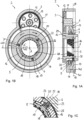
- FIGS. 4A and 4B show an actuator arrangement 2 according to the invention in a second embodiment, which corresponds to the embodiment according to the Figures 1A to 1C corresponds in many respects, so that reference is made to the above description with regard to the similarities. Identical or corresponding details are provided with the same reference numerals.
- a difference of the present embodiment according to the Figures 4A and 4B is that the locking ring 5 is not actuated, i.e. rotated, by the rotationally driven ramp ring 6, but by the axially supported ramp ring 8.
- the locking element 5 is connected to the second ramp ring 8 in a rotationally fixed manner via the connecting elements 18, so that both rotate together about the axis of rotation A.
- the friction surface pairing in the power path is formed between the rotationally drivable first ramp ring 6 and the second ramp ring 8.
- the first ramp ring 6 continues to rotate relative to them.
- the balls roll in the ball grooves 7, 9 in the direction of flatter sections, so that the first ramp ring 6 is pushed axially away from the second ramp ring 6.
- the connecting elements 18 are designed as one piece with the ring section 15, which engage in a form-fitting manner in corresponding recesses 37 of the ramp ring 8, so that both are connected to one another in a rotationally fixed manner.
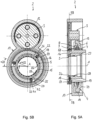
- FIGS 5A and 5B show an actuator arrangement 2 according to the invention in a further embodiment, which largely corresponds to the embodiment according to Figures 1A to 1C.
- FIG. 5B shows an actuator arrangement 2 according to the invention in a further embodiment, which largely corresponds to the embodiment according to Figures 1A to 1C.
- a difference of the present embodiment according to the Figures 5A and 5B is that the actuating ring 59 for rotating the locking ring 5 is not formed on the rotationally driven ramp ring, but is designed in the form of a separate intermediate ring.
- the intermediate ring 59 which can also be referred to as an intermediate gear, engages in the first toothing 12 of the drive gear 3 and is driven in rotation by it.
- the two toothings 12, 13 of the drive gear 3 have a different diameter or a different number of teeth, so that the first gear pair (12, 58) has a different transmission ratio than the second gear pair (13, 14).
- the intermediate gear 59 is mounted with an inner circumferential surface on a bearing seat 58 of the sleeve-shaped housing part 16 so as to be rotatable about the axis of rotation A.
- the intermediate gear 59 is driven in a correspondingly rotating manner, with which the locking ring 5 is in contact via friction surface pairs.
- the friction surface pairing is formed between the contact surfaces of the connecting elements 18 and an inner circumferential surface 19 of the intermediate gear 38.
- the spring preload causes the connecting elements 18 to come into frictional contact with the inner surface 19 of the intermediate wheel 59, so that when the intermediate wheel 59 rotates, they rotate with it until they hit one or the other rotation stop 23, 24, depending on the direction of rotation. After reaching the respective rotation stop, the intermediate wheel 59 continues to rotate, but the locking ring 5 remains in its rotational position and the connecting elements 18 slide along the inner surface 19 of the intermediate wheel.
- the ball ramp arrangement 4 is designed essentially as in the above embodiments. By rotating the first ramp ring 6 relative to the second ramp ring 8, the balls migrate to flatter areas so that the first ramp ring 6 is moved axially away from the second ramp ring 8, for example to actuate a friction clutch.
Landscapes
- Engineering & Computer Science (AREA)
- General Engineering & Computer Science (AREA)
- Mechanical Engineering (AREA)
- Physics & Mathematics (AREA)
- Electromagnetism (AREA)
- Mechanical Operated Clutches (AREA)
- Arrangement And Mounting Of Devices That Control Transmission Of Motive Force (AREA)
Claims (15)
- Ensemble actionneur pour un dispositif d'embrayage dans la chaîne cinématique d'un véhicule automobile, comprenant :une roue d'entraînement (3) pouvant être entraînée en rotation ;une première bague de rampe (6) pouvant être entraînée en rotation par la roue d'entraînement (3) et une deuxième bague de rampe (8), la première bague de rampe (6) et la deuxième bague de rampe (8) étant soutenues axialement l'une par rapport à l'autre, et étant conçues pour convertir un mouvement de rotation relatif en un mouvement axial ;caractérisé parune bague de blocage (5) qui est montée dans un boîtier fixe (17) de manière à pouvoir tourner autour d'un axe de rotation (A) et qui est reliée en entraînement à la roue d'entraînement (3) par l'intermédiaire d'un chemin de puissance, la bague de blocage (5) pouvant être tournée par la roue d'entraînement (3) d'une première position de rotation (Pr1) contre une butée de rotation (23, 24) dans une deuxième position de rotation (Pr2) ;au moins une paire de surfaces de friction (28, 19 ; 7, 9) étant prévue dans le chemin de puissance entre la roue d'entraînement (3) et la bague de blocage (5), par laquelle un couple de rotation peut être transmis à la bague de blocage (5) en utilisant des forces de friction ; etdans lequel, après que la bague de blocage (5) a atteint la butée de rotation (23, 24), la première bague de rampe (6) peut continuer à être entraînée en rotation par la roue d'entraînement (3).
- Ensemble actionneur selon la revendication 1,
caractérisé en ce
que la bague de blocage (5) présente une section annulaire (15) et au moins un élément de liaison (18) faisant saillie de celle-ci pour introduire un couple de rotation dans la bague de blocage (5). - Ensemble actionneur selon l'une des revendications 1 ou 2,
caractérisé en ce
que le boîtier fixe (17) présente une section en forme de douille (16) dans laquelle la bague de blocage (5) est logée de manière à pouvoir tourner de manière limitée, la section en forme de douille (16) présentant au moins un passage radial (20) dans lequel s'engage le au moins un élément de liaison (18) de la bague de blocage (5). - Ensemble actionneur selon l'une quelconque des revendications 1 à 3,
caractérisé en ce
que le au moins un élément de liaison (18) de la bague de blocage (5) peut être tourné par une bague d'actionnement (59) disposée dans le chemin de puissance entre la roue d'entraînement (3) et la bague de blocage (5). - Ensemble actionneurs selon la revendication 4,
caractérisé en ce
que la bague de blocage (5) présente au moins un élément de ressort (25) pour précontraindre élastiquement le au moins un élément de liaison (18), le au moins un élément de liaison (18) étant sollicité élastiquement par le au moins un élément de ressort (25) contre la bague d'actionnement (59) et étant en contact de friction avec celle-ci. - Ensemble actionneurs selon la revendication 5,
caractérisé en ce
que la bague d'actionnement (59) est reliée solidairement en rotation à la première bague de rampe (6) pouvant être entraînée en rotation, en particulier est réalisée d'une seule pièce avec celle-ci, l'appariement de surfaces de frottement étant formé entre une surface de contact de l'élément de liaison (18) et une surface d'appui (19) de la bague d'actionnement (59). - Ensemble actionneurs selon la revendication 5,
caractérisé en ce
que la bague d'actionnement (59) est conçu sous la forme d'une roue intermédiaire qui peut être entraînée en rotation autour de l'axe de rotation (A) par la roue d'entraînement (3), l'appariement de surfaces de friction étant formé entre une surface de contact de l'élément de liaison (18) et une surface d'appui (19) de la roue intermédiaire (38). - Ensemble actionneurs selon la revendication 6,
caractérisé en ce
que la roue d'entraînement (3) présente une première denture (12) pour l'entraînement de la roue intermédiaire et une deuxième denture (13) pour l'entraînement de la première bague de rampe (6), les deux dentures (12, 13) présentant un diamètre différent. - Ensemble actionneurs selon la revendication 4,
caractérisé en ce
que la bague de blocage (5) est reliée solidairement en rotation à la deuxième bague en rampe (8) par l'intermédiaire de l'au moins un élément de liaison (18), de sorte que les deux tournent ensemble, l'appariement de surfaces de friction étant formé dans le chemin de puissance entre la première bague en rampe (6) pouvant être entraînée en rotation et la deuxième bague en rampe (8). - Ensemble actionneur selon l'une quelconque des revendications 1 à 9,
caractérisé en ce
que le premier anneau de rampe (6) et le deuxième anneau de rampe (8) sont indirectement supportés axialement l'un par rapport à l'autre par des billes qui se déplacent dans des rainures de billes correspondantes (7, 9) des premier et deuxième anneaux de rampe (6, 8). - Ensemble actionneur selon l'une quelconque des revendications 1 à 10,
caractérisé en ceque la deuxième bague de rampe (8) est soutenue axialement contre le boîtier fixe (17), la première bague de rampe (6) pouvant être déplacée, par entraînement en rotation au moyen de la roue d'entraînement (3), d'une première position axiale (Pa1), dans laquelle la première bague de rampe (6) est axialement rapprochée de la deuxième bague de rampe (8), à une deuxième position axiale (Pa2), dans laquelle la première bague de rampe (6) est axialement espacée de la deuxième bague de rampe (8),la première bague de rampe (6) présentant, sur son côté opposé à la deuxième bague de rampe (8), une surface d'actionnement (39) pour solliciter axialement un embrayage à friction (40). - Ensemble d'entraînement avec un ensemble actionneur selon l'une des revendications 1 à 11, comprenantun accouplement à verrouillage de forme (30) avec un premier élément d'accouplement (31) et un deuxième élément d'accouplement (32) mobile axialement par rapport à celui-ci, le deuxième élément d'accouplement (32) étant relié solidairement en rotation au premier élément d'accouplement (31) dans une position de fermeture et étant découplé du premier élément d'accouplement (31) dans une position d'ouverture afin de pouvoir tourner librement par rapport à celui-ci,un embrayage à friction (40) pour la transmission variable du couple entre une première partie d'embrayage (41) et une deuxième partie d'embrayage (42),dans lequel la bague de blocage (5) de l'ensemble actionneur bloque, dans la première position de rotation (Pr1), un mouvement axial du deuxième élément d'accouplement (32) de l'accouplement à verrouillage de forme (30), l'accouplement à verrouillage de forme étant fermé,dans lequel la bague de blocage (5), en tournant dans la deuxième position de rotation (Pr2) au moyen de la roue d'entraînement (3), libère le deuxième élément d'accouplement (32) de l'accouplement à verrouillage de forme, de sorte que l'accouplement à verrouillage de forme (30) est ouvert,dans lequel, lorsque la roue d'entraînement (3) continue à tourner, la bague de blocage (5) reste dans la deuxième position de rotation (Pr2) et l'embrayage à friction (40) est sollicité dans le sens de la fermeture par la première bague en rampe (6) pouvant être entraînée en rotation.
- Ensemble d'entraînement selon la revendication 12,
caractérisé en ce
que l'embrayage à friction (40) présente un paquet de lamelles (47) entre la première partie d'embrayage (41) et la deuxième partie d'embrayage (42), le paquet de lamelles (47) pouvant être sollicité axialement par une plaque de pression (49) qui peut être actionnée par la première bague à rampe (6), un palier axial (52) étant prévu entre la première bague à rampe (6) et la plaque de pression (49) pour le découplage en rotation. - Ensemble d'entraînement selon l'une des revendications 12 ou 13,
caractérisé en cequ'il est prévu un engrenage planétaire (60) avecune roue d'entrée (63) qui peut être entraînée en rotation par la machine électrique autour d'un axe de rotation (A),une roue d'appui (64) qui est disposée de manière à pouvoir tourner coaxiale-ment à la roue d'entrée (63) et qui est reliée de manière solidaire en rotation au premier élément d'accouplement (31) de l'accouplement à verrouillage de forme (30), la roue d'appui (64) étant appuyée dans le sens de rotation sur le composant fixe (17) dans la position de fermeture de l'accouplement à verrouillage de forme (30), et pouvant tourner librement dans une position d'ouverture de l'accouplement à verrouillage de forme (30),une pluralité de roues planétaires (65) engrenant avec la roue d'entrée (63) et la roue de support (64), etun élément porteur (66) sur lequel les roues planétaires (65) sont montées à rotation et qui peut être entraîné en rotation autour de l'axe de rotation (A) afin de transmettre un couple à une unité d'entraînement (70) située en aval,dans lequel l'embrayage à friction (40) est disposé dans le chemin de puissance entre l'une des parties roue d'entrée (63), roue de support (64) et élément de support (66) et une autre des parties roue d'entrée (63), roue de support (64) et élément de support (66), etl'élément de support (66) du engrenage planétaire (60) étant relié en entraînement à une unité de ramification de puissance (70) située en aval, qui est conçue en particulier sous la forme d'un engrenage différentiel. - Ensemble d'entraînement selon l'une quelconque des revendications 12 à 14,
caractérisé en ceque, en position de fermeture de l'embrayage à verrouillage de forme (30) et en position d'ouverture de l'embrayage à friction (40), un premier rapport de transmission (i1) est formé entre la roue d'entrée (63) et l'élément de support (66), eten position ouverte de l'embrayage à verrouillage de forme (30), un couple variable peut être transmis entre la roue d'entrée (63) et l'élément porteur (66) au moyen de l'embrayage à friction (40), un deuxième rapport de transmission (i2) étant formé entre la roue d'entrée (63) et l'élément porteur (66) lorsque l'embrayage à friction (40) est complètement fermé.
Applications Claiming Priority (1)
| Application Number | Priority Date | Filing Date | Title |
|---|---|---|---|
| PCT/EP2019/050689 WO2020143921A1 (fr) | 2019-01-11 | 2019-01-11 | Arrangement actionneur pour un arrangement d'accouplement pour une chaîne cinématique d'un véhicule automobile |
Publications (2)
| Publication Number | Publication Date |
|---|---|
| EP3908765A1 EP3908765A1 (fr) | 2021-11-17 |
| EP3908765B1 true EP3908765B1 (fr) | 2024-10-23 |
Family
ID=65200783
Family Applications (1)
| Application Number | Title | Priority Date | Filing Date |
|---|---|---|---|
| EP19701455.8A Active EP3908765B1 (fr) | 2019-01-11 | 2019-01-11 | Arrangement actionneur pour un arrangement d'accouplement pour une chaîne cinématique d'un véhicule automobile |
Country Status (4)
| Country | Link |
|---|---|
| US (1) | US11454288B2 (fr) |
| EP (1) | EP3908765B1 (fr) |
| CN (1) | CN113227598B (fr) |
| WO (1) | WO2020143921A1 (fr) |
Families Citing this family (2)
| Publication number | Priority date | Publication date | Assignee | Title |
|---|---|---|---|---|
| EP4050239A1 (fr) | 2021-02-24 | 2022-08-31 | Ningbo Geely Automobile Research & Development Co. Ltd. | Une unité de différentiel, un véhicule comprenant l'unité de différentiel, et un procédé pour faire fonctionner l'unité de différentiel |
| CN118511016A (zh) * | 2022-01-13 | 2024-08-16 | 日本精工株式会社 | 动力传递路径切换装置以及二级变速器 |
Citations (1)
| Publication number | Priority date | Publication date | Assignee | Title |
|---|---|---|---|---|
| EP3543554A1 (fr) * | 2018-02-19 | 2019-09-25 | Nsk-Warner K.K. | Appareil à embrayage |
Family Cites Families (16)
| Publication number | Priority date | Publication date | Assignee | Title |
|---|---|---|---|---|
| JP4259705B2 (ja) * | 1999-12-13 | 2009-04-30 | 株式会社ジェイテクト | カム機構とこれを用いたクラッチ装置 |
| DE10151960C2 (de) * | 2001-10-20 | 2003-09-11 | Gkn Automotive Gmbh | Verfahren zur Rückverstellung einer Axialverstellvorrichtung |
| US7021442B2 (en) * | 2004-03-16 | 2006-04-04 | General Motors Corporation | One-way torque transmitter with a friction actuating apparatus |
| DE102005022926B3 (de) | 2005-05-13 | 2007-02-01 | Getrag Innovations Gmbh | Antriebseinheit für ein Kraftfahrzeug |
| DE102008063904B4 (de) | 2008-12-19 | 2012-10-25 | Gkn Driveline International Gmbh | Antriebsanordnung |
| FR2969242B1 (fr) * | 2010-12-16 | 2013-07-05 | Peugeot Citroen Automobiles Sa | Dispositif de transmission de couple, et boite de vitesses le comportant |
| JP6333398B2 (ja) * | 2014-02-14 | 2018-05-30 | ジー・ケー・エヌ オートモーティヴ リミテッドGKN Automotive Limited | 継手アセンブリおよびこのような継手アセンブリを備える動力伝達経路アセンブリ |
| JP2015206423A (ja) * | 2014-04-22 | 2015-11-19 | トヨタ自動車株式会社 | カム機構 |
| JP6576767B2 (ja) * | 2015-09-28 | 2019-09-18 | Ntn株式会社 | 逆入力遮断装置 |
| CN108779821A (zh) * | 2016-01-19 | 2018-11-09 | Gkn汽车有限公司 | 具有离合器坡道单元的离合器组件和控制离合器组件的方法 |
| PL3488117T3 (pl) * | 2016-07-20 | 2020-10-19 | Gkn Automotive Limited | Układ aktuatora i układ sprzęgła |
| DE102016217053B4 (de) * | 2016-09-08 | 2018-08-16 | Schaeffler Technologies AG & Co. KG | Aktuator für eine Keil- und/ oder Lamellenkupplung |
| TWI638102B (zh) * | 2016-09-10 | 2018-10-11 | 本土股份有限公司 | 變速機構 |
| JP6418218B2 (ja) * | 2016-10-06 | 2018-11-07 | トヨタ自動車株式会社 | 車両用差動制限装置 |
| EP3701162A1 (fr) * | 2017-10-26 | 2020-09-02 | Schaeffler Technologies AG & Co. KG | Dispositif et procédé de synchronisation |
| US10935087B2 (en) * | 2018-08-08 | 2021-03-02 | Team Industries, Inc. | Clutch assembly |
-
2019
- 2019-01-11 US US17/419,875 patent/US11454288B2/en active Active
- 2019-01-11 EP EP19701455.8A patent/EP3908765B1/fr active Active
- 2019-01-11 WO PCT/EP2019/050689 patent/WO2020143921A1/fr not_active Ceased
- 2019-01-11 CN CN201980088601.3A patent/CN113227598B/zh active Active
Patent Citations (1)
| Publication number | Priority date | Publication date | Assignee | Title |
|---|---|---|---|---|
| EP3543554A1 (fr) * | 2018-02-19 | 2019-09-25 | Nsk-Warner K.K. | Appareil à embrayage |
Also Published As
| Publication number | Publication date |
|---|---|
| CN113227598B (zh) | 2023-11-14 |
| CN113227598A (zh) | 2021-08-06 |
| EP3908765A1 (fr) | 2021-11-17 |
| WO2020143921A1 (fr) | 2020-07-16 |
| US11454288B2 (en) | 2022-09-27 |
| US20220082137A1 (en) | 2022-03-17 |
Similar Documents
| Publication | Publication Date | Title |
|---|---|---|
| EP3354920B1 (fr) | Système d'embrayage pour un groupe propulseur et transmission comprenant un tel système d'embrayage | |
| EP3405693B1 (fr) | Système d'embrayage à ensemble rampes et billes et procédé pour assurer la commande d'un système d'embrayage | |
| DE10311427B4 (de) | Differentialgetriebe | |
| DE102008063904B4 (de) | Antriebsanordnung | |
| EP3488117B1 (fr) | Ensemble actionneur et ensemble embrayage | |
| WO2010017881A1 (fr) | Agencement d'accouplement et agencement de chaîne cinématique pour un véhicule automobile à plusieurs essieux entraînés | |
| DE102018105982A1 (de) | Schaltvorrichtung für ein Kraftfahrzeug sowie Kraftfahrzeuggetriebe | |
| EP0368140B1 (fr) | Méthode de réglage d'embrayages ou de freins | |
| DE102005061267B4 (de) | Differentialanordnung mit zwei gemeinsam betätigten Axialverstellvorrichtungen | |
| AT5363U1 (de) | Verteilergetriebe mit steuerbarer reibungskupplung | |
| DE102017127146B3 (de) | Schaltgetriebe und Elektroantrieb mit einem Schaltgetriebe | |
| WO2017088875A1 (fr) | Système d'embrayage pour un véhicule et véhicule équipé dudit système d'embrayage | |
| AT510922B1 (de) | Getriebeanordnung zur variablen drehmomentverteilung | |
| DE112018005564T5 (de) | Schnittstellenmodul für einen antriebsstrang | |
| EP3908765B1 (fr) | Arrangement actionneur pour un arrangement d'accouplement pour une chaîne cinématique d'un véhicule automobile | |
| WO2015180717A2 (fr) | Dispositif de synchronisation | |
| DE102014214297B4 (de) | Kupplungsanordnung | |
| EP2861445B1 (fr) | Démultiplicateur et différentiel et unité à motoréducteur | |
| DE102012223792A1 (de) | Schalteinrichtung für ein Planetengetriebe | |
| DE202005017525U1 (de) | Reibungskupplung | |
| DE102004004931A1 (de) | Lamellenkupplung mit konischen Lamellen | |
| DE102015120818B4 (de) | Getriebe mit schaltbarem Planetensatz sowie Freilaufkupplung für ein elektrisch antreibbares Kraftfahrzeug | |
| DE102015100906B4 (de) | Synchronisiereinrichtung, Kupplungsanordnung und Antriebsanordnung | |
| WO2019052636A1 (fr) | Embrayage à roue libre présentant une force de réglage induite par frottement | |
| DE102012022636B4 (de) | Querdifferential mit elektromechanischer Reibkupplung zur Sperrung |
Legal Events
| Date | Code | Title | Description |
|---|---|---|---|
| STAA | Information on the status of an ep patent application or granted ep patent |
Free format text: STATUS: UNKNOWN |
|
| STAA | Information on the status of an ep patent application or granted ep patent |
Free format text: STATUS: THE INTERNATIONAL PUBLICATION HAS BEEN MADE |
|
| PUAI | Public reference made under article 153(3) epc to a published international application that has entered the european phase |
Free format text: ORIGINAL CODE: 0009012 |
|
| STAA | Information on the status of an ep patent application or granted ep patent |
Free format text: STATUS: REQUEST FOR EXAMINATION WAS MADE |
|
| 17P | Request for examination filed |
Effective date: 20210618 |
|
| AK | Designated contracting states |
Kind code of ref document: A1 Designated state(s): AL AT BE BG CH CY CZ DE DK EE ES FI FR GB GR HR HU IE IS IT LI LT LU LV MC MK MT NL NO PL PT RO RS SE SI SK SM TR |
|
| DAV | Request for validation of the european patent (deleted) | ||
| DAX | Request for extension of the european patent (deleted) | ||
| STAA | Information on the status of an ep patent application or granted ep patent |
Free format text: STATUS: EXAMINATION IS IN PROGRESS |
|
| 17Q | First examination report despatched |
Effective date: 20220808 |
|
| GRAP | Despatch of communication of intention to grant a patent |
Free format text: ORIGINAL CODE: EPIDOSNIGR1 |
|
| STAA | Information on the status of an ep patent application or granted ep patent |
Free format text: STATUS: GRANT OF PATENT IS INTENDED |
|
| INTG | Intention to grant announced |
Effective date: 20240516 |
|
| P01 | Opt-out of the competence of the unified patent court (upc) registered |
Free format text: CASE NUMBER: APP_32789/2024 Effective date: 20240531 |
|
| GRAS | Grant fee paid |
Free format text: ORIGINAL CODE: EPIDOSNIGR3 |
|
| GRAA | (expected) grant |
Free format text: ORIGINAL CODE: 0009210 |
|
| STAA | Information on the status of an ep patent application or granted ep patent |
Free format text: STATUS: THE PATENT HAS BEEN GRANTED |
|
| AK | Designated contracting states |
Kind code of ref document: B1 Designated state(s): AL AT BE BG CH CY CZ DE DK EE ES FI FR GB GR HR HU IE IS IT LI LT LU LV MC MK MT NL NO PL PT RO RS SE SI SK SM TR |
|
| REG | Reference to a national code |
Ref country code: GB Ref legal event code: FG4D Free format text: NOT ENGLISH |
|
| REG | Reference to a national code |
Ref country code: CH Ref legal event code: EP |
|
| REG | Reference to a national code |
Ref country code: DE Ref legal event code: R096 Ref document number: 502019012340 Country of ref document: DE |
|
| REG | Reference to a national code |
Ref country code: IE Ref legal event code: FG4D Free format text: LANGUAGE OF EP DOCUMENT: GERMAN |
|
| REG | Reference to a national code |
Ref country code: LT Ref legal event code: MG9D |
|
| REG | Reference to a national code |
Ref country code: NL Ref legal event code: MP Effective date: 20241023 |
|
| PG25 | Lapsed in a contracting state [announced via postgrant information from national office to epo] |
Ref country code: NL Free format text: LAPSE BECAUSE OF FAILURE TO SUBMIT A TRANSLATION OF THE DESCRIPTION OR TO PAY THE FEE WITHIN THE PRESCRIBED TIME-LIMIT Effective date: 20241023 |
|
| PG25 | Lapsed in a contracting state [announced via postgrant information from national office to epo] |
Ref country code: NL Free format text: LAPSE BECAUSE OF FAILURE TO SUBMIT A TRANSLATION OF THE DESCRIPTION OR TO PAY THE FEE WITHIN THE PRESCRIBED TIME-LIMIT Effective date: 20241023 |
|
| PG25 | Lapsed in a contracting state [announced via postgrant information from national office to epo] |
Ref country code: IS Free format text: LAPSE BECAUSE OF FAILURE TO SUBMIT A TRANSLATION OF THE DESCRIPTION OR TO PAY THE FEE WITHIN THE PRESCRIBED TIME-LIMIT Effective date: 20250223 Ref country code: HR Free format text: LAPSE BECAUSE OF FAILURE TO SUBMIT A TRANSLATION OF THE DESCRIPTION OR TO PAY THE FEE WITHIN THE PRESCRIBED TIME-LIMIT Effective date: 20241023 Ref country code: PT Free format text: LAPSE BECAUSE OF FAILURE TO SUBMIT A TRANSLATION OF THE DESCRIPTION OR TO PAY THE FEE WITHIN THE PRESCRIBED TIME-LIMIT Effective date: 20250224 |
|
| PG25 | Lapsed in a contracting state [announced via postgrant information from national office to epo] |
Ref country code: FI Free format text: LAPSE BECAUSE OF FAILURE TO SUBMIT A TRANSLATION OF THE DESCRIPTION OR TO PAY THE FEE WITHIN THE PRESCRIBED TIME-LIMIT Effective date: 20241023 |
|
| PG25 | Lapsed in a contracting state [announced via postgrant information from national office to epo] |
Ref country code: BG Free format text: LAPSE BECAUSE OF FAILURE TO SUBMIT A TRANSLATION OF THE DESCRIPTION OR TO PAY THE FEE WITHIN THE PRESCRIBED TIME-LIMIT Effective date: 20241023 |
|
| PG25 | Lapsed in a contracting state [announced via postgrant information from national office to epo] |
Ref country code: ES Free format text: LAPSE BECAUSE OF FAILURE TO SUBMIT A TRANSLATION OF THE DESCRIPTION OR TO PAY THE FEE WITHIN THE PRESCRIBED TIME-LIMIT Effective date: 20241023 |
|
| PG25 | Lapsed in a contracting state [announced via postgrant information from national office to epo] |
Ref country code: NO Free format text: LAPSE BECAUSE OF FAILURE TO SUBMIT A TRANSLATION OF THE DESCRIPTION OR TO PAY THE FEE WITHIN THE PRESCRIBED TIME-LIMIT Effective date: 20250123 |
|
| PG25 | Lapsed in a contracting state [announced via postgrant information from national office to epo] |
Ref country code: LV Free format text: LAPSE BECAUSE OF FAILURE TO SUBMIT A TRANSLATION OF THE DESCRIPTION OR TO PAY THE FEE WITHIN THE PRESCRIBED TIME-LIMIT Effective date: 20241023 Ref country code: GR Free format text: LAPSE BECAUSE OF FAILURE TO SUBMIT A TRANSLATION OF THE DESCRIPTION OR TO PAY THE FEE WITHIN THE PRESCRIBED TIME-LIMIT Effective date: 20250124 |
|
| PG25 | Lapsed in a contracting state [announced via postgrant information from national office to epo] |
Ref country code: PL Free format text: LAPSE BECAUSE OF FAILURE TO SUBMIT A TRANSLATION OF THE DESCRIPTION OR TO PAY THE FEE WITHIN THE PRESCRIBED TIME-LIMIT Effective date: 20241023 |
|
| PG25 | Lapsed in a contracting state [announced via postgrant information from national office to epo] |
Ref country code: RS Free format text: LAPSE BECAUSE OF FAILURE TO SUBMIT A TRANSLATION OF THE DESCRIPTION OR TO PAY THE FEE WITHIN THE PRESCRIBED TIME-LIMIT Effective date: 20250123 |
|
| PG25 | Lapsed in a contracting state [announced via postgrant information from national office to epo] |
Ref country code: SM Free format text: LAPSE BECAUSE OF FAILURE TO SUBMIT A TRANSLATION OF THE DESCRIPTION OR TO PAY THE FEE WITHIN THE PRESCRIBED TIME-LIMIT Effective date: 20241023 |
|
| PG25 | Lapsed in a contracting state [announced via postgrant information from national office to epo] |
Ref country code: DK Free format text: LAPSE BECAUSE OF FAILURE TO SUBMIT A TRANSLATION OF THE DESCRIPTION OR TO PAY THE FEE WITHIN THE PRESCRIBED TIME-LIMIT Effective date: 20241023 |
|
| PG25 | Lapsed in a contracting state [announced via postgrant information from national office to epo] |
Ref country code: EE Free format text: LAPSE BECAUSE OF FAILURE TO SUBMIT A TRANSLATION OF THE DESCRIPTION OR TO PAY THE FEE WITHIN THE PRESCRIBED TIME-LIMIT Effective date: 20241023 |
|
| PG25 | Lapsed in a contracting state [announced via postgrant information from national office to epo] |
Ref country code: RO Free format text: LAPSE BECAUSE OF FAILURE TO SUBMIT A TRANSLATION OF THE DESCRIPTION OR TO PAY THE FEE WITHIN THE PRESCRIBED TIME-LIMIT Effective date: 20241023 |
|
| REG | Reference to a national code |
Ref country code: DE Ref legal event code: R097 Ref document number: 502019012340 Country of ref document: DE |
|
| PG25 | Lapsed in a contracting state [announced via postgrant information from national office to epo] |
Ref country code: SK Free format text: LAPSE BECAUSE OF FAILURE TO SUBMIT A TRANSLATION OF THE DESCRIPTION OR TO PAY THE FEE WITHIN THE PRESCRIBED TIME-LIMIT Effective date: 20241023 |
|
| PG25 | Lapsed in a contracting state [announced via postgrant information from national office to epo] |
Ref country code: CZ Free format text: LAPSE BECAUSE OF FAILURE TO SUBMIT A TRANSLATION OF THE DESCRIPTION OR TO PAY THE FEE WITHIN THE PRESCRIBED TIME-LIMIT Effective date: 20241023 |
|
| PG25 | Lapsed in a contracting state [announced via postgrant information from national office to epo] |
Ref country code: IT Free format text: LAPSE BECAUSE OF FAILURE TO SUBMIT A TRANSLATION OF THE DESCRIPTION OR TO PAY THE FEE WITHIN THE PRESCRIBED TIME-LIMIT Effective date: 20241023 |
|
| PLBE | No opposition filed within time limit |
Free format text: ORIGINAL CODE: 0009261 |
|
| REG | Reference to a national code |
Ref country code: CH Ref legal event code: PL |
|
| STAA | Information on the status of an ep patent application or granted ep patent |
Free format text: STATUS: NO OPPOSITION FILED WITHIN TIME LIMIT |
|
| PG25 | Lapsed in a contracting state [announced via postgrant information from national office to epo] |
Ref country code: SE Free format text: LAPSE BECAUSE OF FAILURE TO SUBMIT A TRANSLATION OF THE DESCRIPTION OR TO PAY THE FEE WITHIN THE PRESCRIBED TIME-LIMIT Effective date: 20241023 |
|
| PG25 | Lapsed in a contracting state [announced via postgrant information from national office to epo] |
Ref country code: MC Free format text: LAPSE BECAUSE OF FAILURE TO SUBMIT A TRANSLATION OF THE DESCRIPTION OR TO PAY THE FEE WITHIN THE PRESCRIBED TIME-LIMIT Effective date: 20241023 Ref country code: LU Free format text: LAPSE BECAUSE OF NON-PAYMENT OF DUE FEES Effective date: 20250111 |
|
| GBPC | Gb: european patent ceased through non-payment of renewal fee |
Effective date: 20250123 |
|
| 26N | No opposition filed |
Effective date: 20250724 |
|
| PG25 | Lapsed in a contracting state [announced via postgrant information from national office to epo] |
Ref country code: BE Free format text: LAPSE BECAUSE OF NON-PAYMENT OF DUE FEES Effective date: 20250131 Ref country code: GB Free format text: LAPSE BECAUSE OF NON-PAYMENT OF DUE FEES Effective date: 20250123 |
|
| PG25 | Lapsed in a contracting state [announced via postgrant information from national office to epo] |
Ref country code: FR Free format text: LAPSE BECAUSE OF NON-PAYMENT OF DUE FEES Effective date: 20250131 |
|
| PG25 | Lapsed in a contracting state [announced via postgrant information from national office to epo] |
Ref country code: CH Free format text: LAPSE BECAUSE OF NON-PAYMENT OF DUE FEES Effective date: 20250131 |
|
| REG | Reference to a national code |
Ref country code: BE Ref legal event code: MM Effective date: 20250131 |
|
| PG25 | Lapsed in a contracting state [announced via postgrant information from national office to epo] |
Ref country code: IE Free format text: LAPSE BECAUSE OF NON-PAYMENT OF DUE FEES Effective date: 20250111 |
|
| REG | Reference to a national code |
Ref country code: AT Ref legal event code: MM01 Ref document number: 1735060 Country of ref document: AT Kind code of ref document: T Effective date: 20250111 |
|
| PGFP | Annual fee paid to national office [announced via postgrant information from national office to epo] |
Ref country code: DE Payment date: 20260120 Year of fee payment: 8 |
|
| PG25 | Lapsed in a contracting state [announced via postgrant information from national office to epo] |
Ref country code: AT Free format text: LAPSE BECAUSE OF NON-PAYMENT OF DUE FEES Effective date: 20250111 |