EP3909064B1 - Anschlussleiste - Google Patents
Anschlussleiste Download PDFInfo
- Publication number
- EP3909064B1 EP3909064B1 EP20700009.2A EP20700009A EP3909064B1 EP 3909064 B1 EP3909064 B1 EP 3909064B1 EP 20700009 A EP20700009 A EP 20700009A EP 3909064 B1 EP3909064 B1 EP 3909064B1
- Authority
- EP
- European Patent Office
- Prior art keywords
- positioning
- holding
- cover
- holder
- frame
- Prior art date
- Legal status (The legal status is an assumption and is not a legal conclusion. Google has not performed a legal analysis and makes no representation as to the accuracy of the status listed.)
- Active
Links
Images




Classifications
-
- H—ELECTRICITY
- H01—ELECTRIC ELEMENTS
- H01H—ELECTRIC SWITCHES; RELAYS; SELECTORS; EMERGENCY PROTECTIVE DEVICES
- H01H71/00—Details of the protective switches or relays covered by groups H01H73/00 - H01H83/00
- H01H71/08—Terminals; Connections
-
- H—ELECTRICITY
- H01—ELECTRIC ELEMENTS
- H01H—ELECTRIC SWITCHES; RELAYS; SELECTORS; EMERGENCY PROTECTIVE DEVICES
- H01H71/00—Details of the protective switches or relays covered by groups H01H73/00 - H01H83/00
- H01H71/02—Housings; Casings; Bases; Mountings
- H01H71/0207—Mounting or assembling the different parts of the circuit breaker
- H01H71/0214—Housing or casing lateral walls containing guiding grooves or special mounting facilities
-
- H—ELECTRICITY
- H01—ELECTRIC ELEMENTS
- H01H—ELECTRIC SWITCHES; RELAYS; SELECTORS; EMERGENCY PROTECTIVE DEVICES
- H01H71/00—Details of the protective switches or relays covered by groups H01H73/00 - H01H83/00
- H01H71/02—Housings; Casings; Bases; Mountings
- H01H2071/0292—Housing or frames containing grooves or slots for guiding movable parts
-
- H—ELECTRICITY
- H01—ELECTRIC ELEMENTS
- H01H—ELECTRIC SWITCHES; RELAYS; SELECTORS; EMERGENCY PROTECTIVE DEVICES
- H01H71/00—Details of the protective switches or relays covered by groups H01H73/00 - H01H83/00
- H01H71/08—Terminals; Connections
- H01H2071/086—Low power connections for auxiliary switches, e.g. shunt trip
-
- H—ELECTRICITY
- H01—ELECTRIC ELEMENTS
- H01H—ELECTRIC SWITCHES; RELAYS; SELECTORS; EMERGENCY PROTECTIVE DEVICES
- H01H9/00—Details of switching devices, not covered by groups H01H1/00 - H01H7/00
- H01H9/0066—Auxiliary contact devices
Definitions
- connection terminal block capable of being fixed to a chassis of electrical switching equipment, electrical switching equipment comprising a chassis and such a connection terminal block as well as a method of mounting such electrical equipment cut-off.
- connection terminal block is for example known from the document EP 0 986 153 A1 .
- This connection terminal block can be fixed to a chassis of electrical switching equipment using screws. Fixing the terminal block to the chassis using screws has the disadvantage of being time-consuming and not easy.
- the present invention aims to overcome these drawbacks.
- the aim of the present invention is to provide a connection terminal block that is easy and quick to install.
- connection terminal block without cover in accordance with the preamble of claim 1.
- connection terminal block according to the invention is according to claim 1.
- the connection terminal block according to the invention has the advantage of being able to be fixed to the chassis easily and quickly. Securing the cover to the support allows the connection terminal block to be fixed to the chassis by shape conjugation
- the at least one positioning and holding finger is capable of being introduced into the positioning and holding orifice or the positioning and holding recess by a translation movement carried out in parallel to a first direction and the at least one lug is able to be slid into the positioning and holding slide by a translation movement carried out in parallel to a second direction, the first direction and the second direction being either left relative to each other, or secant.
- the at least one positioning and holding finger is capable of being introduced into the positioning and holding orifice or the positioning and holding recess by a translation movement carried out in parallel to a first direction and the at least one lug is able to be slid into the positioning and holding slide by a translation movement carried out in parallel to a second direction, the first direction and the second direction being parallel to each other and opposite.
- connection terminal block can be easily fixed to the chassis.
- the support being secured to the cover, the slide for positioning and holding the chassis and the lug for positioning and holding the cover prevent retraction of the support secured to the cover in the direction opposite to the first direction.
- the positioning and holding finger of the support and the positioning and holding hole or the positioning and holding recess of the chassis prevent retraction of the cover secured to the support in the direction opposite to the second direction.
- the at least one positioning and holding finger has an end of essentially constant cross section.
- the positioning and holding orifice or the positioning and holding recess comprises a section of essentially constant cross section.
- the support is provided with at least one tongue capable of being introduced into a positioning and holding slot or a positioning and holding groove of the chassis in order to position the support on the chassis.
- the securing device is able to secure the cover to the support by shape conjugation.
- the invention also relates to electrical switching equipment comprising a frame provided with at least one positioning and holding orifice and/or at least one positioning and holding recess and at least one positioning slide. and holding, and a connection terminal block according to the invention, the at least one positioning and holding finger being introduced into the at least one positioning and holding orifice or the at least one positioning and holding recess holding, the at least one lug being slid into the at least one positioning and holding slide, the securing device securing the cover to the support.
- the method of assembling electrical switching equipment according to the invention has the advantage of allowing simple and easy fixing of the connection terminal to the chassis. Securing the cover to the support allows the connection terminal block to be fixed to the chassis by shape conjugation.
- the at least one positioning and holding finger is introduced into the positioning and holding orifice or the positioning and holding recess by a translation movement carried out in parallel to a first direction and the at least one lug is slid into the positioning and holding slide by a translation movement carried out in parallel to a second direction, the first direction and the second direction being either left relative to each other, or intersecting.
- the securing device secures the cover to the support by shape conjugation.
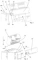
- connection terminal block 10 capable of being fixed on a chassis 110 of an electrical switching device 100, a switching device 100 provided with such a connection terminal block 10 as well as a method of assembling such electrical cut-off equipment 100.
- Such electrical switching equipment 100 may be intended to be placed in an electrical cabinet and may for example be provided with a withdrawable circuit breaker movable in translation inside the chassis 110.
- the circuit breaker may be a high rating circuit breaker going up to for example 6000 A.
- connection terminal 10 can be used to connect external auxiliary devices, such as control devices or remote monitoring devices, to the circuit breaker.
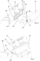
- connection terminal block 10 comprises a support 20 provided with at least one positioning and holding finger 22, a cover 40 provided with at least one positioning and holding pin 42 and a securing device 60.
- the at least one positioning and holding finger 22 of the support 20 is capable of being introduced into a positioning and holding orifice or a positioning and holding recess 112 of the chassis 110 in order to position the support 20 on the chassis 110
- the at least one positioning and holding pin 42 is able to be slid into a positioning and holding slide 114 of the chassis 110 in order to position the cover 40 on the chassis 110.
- the securing device 60 secures the cover 40 to the support 20 when the positioning and holding finger 22 is introduced into the positioning and holding orifice or into the positioning and holding recess 112 and the positioning and holding pin. retaining 42 is slid into the positioning and holding slide 114.
- the frame 110 of the electrical switching equipment 100 can be provided with two positioning and holding recesses 112 and the support 20 can be provided with two positioning and holding fingers 22.
- the support 20 and/or the cover 40 may be provided with housings 28 capable of receiving a plurality of terminals (not shown). Each of these terminals can be intended to be linked to an external auxiliary device.
- connection terminal block 10 has the advantage of being able to be fixed to the chassis 110 easily and quickly. Securing the cover 40 to the support 20 allows the connection terminal block 10 to be fixed to the chassis 110 by shape conjugation.
- the at least one positioning and holding finger 22 may be able to be introduced into the positioning and holding orifice or the positioning and holding recess 112 by a translation movement carried out in parallel to a first direction D1.
- the at least one lug 42 may be able to be slid into the positioning and holding slide 114 by a translation movement carried out in parallel to a second direction D2.
- first direction D1 and the second direction D2 can be either left relative to each other, or intersecting.
- the positioning and holding orifice or the positioning and holding recess 112 can be adapted to allow the insertion of the positioning and holding finger 22 only along the first direction D1.
- the positioning and holding slide 114 can, for its part, be adapted to allow the positioning and holding lug 42 to slide in the positioning and holding slide 114 only along the second direction D2.
- a stop surface 30 of the support 20 can come to bear against an upper surface 118 of the chassis 110.
- a stop surface 44 of the cover 40 can come to bear against a lateral surface 32 of the support 20.
- first direction D1 and the second direction D2 are parallel to each other and in opposite directions.
- connection terminal block 10 can be easily fixed to the chassis 110.
- the support 20 being secured to the cover 40, the positioning and holding slide 114 of the chassis 110 and the positioning and holding lug 42 of the cover 40 prevent the retraction of the support 20 secured to the cover 40 by the securing device 60 in the direction opposite to the first direction D1.
- the positioning and holding finger 22 of the support 20 and the positioning and holding orifice or the positioning and holding recess 112 of the chassis 110 prevent the retraction of the cover 40 secured to the support 20 by the securing device 60 in the direction opposite to the second direction D2.
- the at least one positioning and holding finger 22 may include an end 24 of essentially constant cross section.
- the cross section can be, for example, round, oval, square or rectangular.
- the essentially constant cross section corresponds to a cross section of the end 24 carried out in a plane perpendicular to the first direction D1.
- the support 20 can also be provided with at least one tongue 26 capable of being introduced into a positioning and holding slot or a positioning and holding groove 116 of the chassis in order to position the support 20 on the chassis 110.
- the chassis 110 comprises a positioning and holding groove 116 in which the tongue 26 is inserted when the support 20 is arranged on the chassis 110.
- the tongue 26 can follow at the end 24 of essentially constant cross section.
- the securing device 60 may be able to secure the cover 40 to the support 20 by shape conjugation.
- the securing device 60 may comprise at least one fixing element 62 provided with a head 64, a shaft 66 extending essentially along an axis A and at least one shoulder 68 extending in the direction perpendicular to the axis A from the shaft 66.
- the at least one fixing element 62 can be held on the cover 40 by conjugation of shape.
- the support 20 may include at least one notch 70 in which the at least one shoulder 68 is received in order to secure the cover 40 to the support 20.
- the notch 70 may be present in a cavity 34 of the support 20. Conversely, the notch 70 may be present on the cover 40.
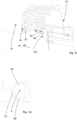
- the fixing element 62 can be held in an orifice 46 of the cover 40.
- the head 64 of the fixing element 62 may have the shape of a cruciform screw head.
- the head 64 and the orifice 46 may have a geometry allowing rotation of the fixing element 62 by 90° around the axis A.
- the fixing element 62 and the notch 70 can be arranged so as to notch the shoulder 68 in the notch 70 following a 90° rotation of the fixing element 62.
- the position of the fixing element 62 before its 90° rotation, where the shoulder 68 is out of the notch 70, is displayed in the Figure 10
- the position of the fixing element 62 after its rotation by 90°, where the shoulder 68 is in the notch 70 is visualized in the Figure 11 .
- a 90° rotation of the fixing element 62 in the opposite direction allows the shoulder to come out of the notch in order to be able to detach the cover 40 from the support 20 and thus allow the detachment of the connection terminal block 10 from the chassis 110.
- the fixing element 62 can be provided with two shoulders 68 extending in a direction perpendicular to the axis A and in a direction opposite to each other from the shaft 66.
- the present application also relates to electrical switching equipment 100 comprising a chassis 110 provided with at least one positioning and holding orifice and/or at least one positioning and holding recess 112 and at least one slide for positioning and holding. positioning and holding 114 and a connection terminal block 10 according to the present application.
- the at least one positioning and holding finger 22 is introduced into the at least one positioning and holding orifice or the at least one positioning and holding recess 112.
- the at least one lug 42 is slipped into the at least one positioning and holding slide 114.
- the securing device 60 secures the cover 40 to the support 20.
- the at least one positioning and holding finger 22 can be introduced into the positioning and holding orifice or the positioning and holding recess 112 by a translation movement carried out in parallel to a first direction D1.
- the at least one lug 42 can be slid into the positioning and holding slide 114 by a translation movement carried out in parallel to a second direction D2.
- the first direction D1 and the second direction D2 can be either left relative to each other or intersecting. According to an alternative, the first direction D1 can be parallel to the second direction D2 and of opposite direction.
- the securing device 60 can secure the cover 40 to the support 20 by shape conjugation.
Landscapes
- Connections Arranged To Contact A Plurality Of Conductors (AREA)
- Connection Or Junction Boxes (AREA)
Claims (10)
- Anschlussleiste, die dazu geeignet ist, an einem Gestell (110) eines elektrischen Schaltgeräts (100) befestigt zu sein, umfassend:- einen Träger (20) der mit mindestens einem Positionierungs- und Haltefinger (22) versehen ist, und- eine Verbindungsvorrichtung (60),wobei der mindestens eine Positionierungs- und Haltefinger (22) dazu geeignet ist, in eine Positionierungs- und Halteöffnung oder eine Positionierungs- und Haltevertiefung (112) des Gestells (110) eingeführt zu werden, um den Träger (20) auf dem Gestell (110) zu positionieren,wobei die Anschlussleiste dadurch gekennzeichnet ist:- dass sie ferner eine Abdeckung (40) umfasst, die mit mindestens einem Positionierungs- und Haltestift (42) versehen ist,- dass der mindestens eine Stift (42) dazu geeignet ist, in eine Positionierungs- und Halteschiene (114) des Gestells (110) eingeschoben zu werden, um die Abdeckung (40) auf dem Gestell (110) zu positionieren,- dass die Verbindungsvorrichtung (60) die Abdeckung (40) mit dem Träger (20) verbindet, wenn der Positionierungs- und Haltefinger (22) in die Positionierungs- und Halteöffnung oder in die Positionierungs- und Haltevertiefung (112) eingeführt ist und wenn der Stift (42) in die Positionierungs- und Halteschiene (114) eingeschoben ist.
- Anschlussleiste nach Anspruch 1, dadurch gekennzeichnet, dass der mindestens eine Positionierungs- und Haltefinger (22) dazu geeignet ist, durch eine parallel zu einer ersten Richtung (D1) ausgeführte Translationsbewegung in die Positionierungs- und Halteöffnung oder die Positionierungs- und Haltevertiefung (112) eingeführt zu werden, und dass der mindestens eine Stift (42) dazu geeignet ist, durch eine parallel zu einer zweiten Richtung (D2) ausgeführte Translationsbewegung in die Positionierungs- und Halteschiene (114) eingeschoben zu werden, wobei die erste Richtung (D1) und die zweite Richtung (D2) entweder windschief zueinander sind oder einander schneiden.
- Anschlussleiste nach einem der Ansprüche 1 oder 2, dadurch gekennzeichnet, dass der mindestens eine Positionierungs- und Haltefinger (22) ein Ende (24) mit einem im Wesentlichen konstanten Querschnitt aufweist.
- Anschlussleiste nach einem der Ansprüche 1 bis 3, dadurch gekennzeichnet, dass der Träger (20) mit mindestens einer Zunge (26) versehen ist, die dazu geeignet ist, in einen Positionierungs- und Halteschlitz oder eine Positionierungs- und Haltenut (116) des Gestells eingeführt zu werden, um den Träger (20) auf dem Gestell (110) zu positionieren.
- Anschlussleiste nach einem der Ansprüche 1 bis 4, dadurch gekennzeichnet, dass die Verbindungsvorrichtung (60) dazu geeignet ist, die Abdeckung (40) formschlüssig mit dem Träger (20) zu verbinden.
- Anschlussleiste nach einem der Ansprüche 1 bis 5, dadurch gekennzeichnet, dass die Verbindungsvorrichtung (60) mindestens ein Befestigungselement (62) umfasst, das mit einem Kopf (64), einem Schaft (66), der sich im Wesentlichen entlang einer Achse (A) erstreckt, und mindestens einer Schulter (68), die sich vom Schaft (66) in einer zur Achse senkrechten Richtung erstreckt, versehen ist, wobei das mindestens eine Befestigungselement (62) formschlüssig auf der Abdeckung (40) gehalten wird, wobei der Träger (20) mindestens eine Kerbe (70) aufweist, in der die Schulter (68) aufgenommen wird, um die Abdeckung (40) mit dem Träger (20) zu verbinden.
- Elektrisches Schaltgerät, umfassend ein Gestell (110), das mit mindestens einer Positionierungs- und Halteöffnung und/oder mindestens einer Positionierungs- und Haltevertiefung (112) und mit mindestens einer Positionierungs- und Halteschiene (114) und einer Anschlussleiste (10) nach einem der Ansprüche 1 bis 6 versehen ist, wobei der mindestens eine Positionierungs- und Haltefinger (22) in die mindestens eine Positionierungs- und Halteöffnung oder die mindestens eine Positionierungs- und Haltevertiefung (112) eingeführt wird, der mindestens eine Stift (42) in die mindestens eine Positionierungs- und Halteschiene (114) eingeschoben wird und die Verbindungsvorrichtung (60) die Abdeckung (40) mit dem Träger (20) verbindet.
- Verfahren zur Montage eines elektrischen Schaltgeräts (100) nach Anspruch 7, gekennzeichnet durch die folgenden Schritte:- Einführen des mindestens einen Positionierungs- und Haltefingers (22) des Trägers (20) in die mindestens eine Positionierungs- und Halteöffnung oder die mindestens eine Positionierungs- und Haltevertiefung (112) des Gestells (110), um den Träger (20) auf dem Gestell (110) zu positionieren;- Einschieben des mindestens einen Stifts (42) der Abdeckung (40) in die mindestens eine Positionierungs- und Halteschiene (114) des Gestells (110), um die Abdeckung (40) auf dem Gestell (110) zu positionieren;
und- Verbinden der Abdeckung (40) mit dem Träger (20) anhand der Verbindungsvorrichtung (60), um die Anschlussklemme (10) am Gestell (110) zu befestigen. - Montageverfahren nach Anspruch 8, dadurch gekennzeichnet, dass der mindestens eine Positionierungs- und Haltefinger (22) durch eine parallel zu einer ersten Richtung (D1) ausgeführte Translationsbewegung in die Positionierungs- und Halteöffnung oder die Positionierungs- und Haltevertiefung (112) eingeführt wird und dass der mindestens eine Stift (42) durch eine parallel zu einer zweiten Richtung (D2) ausgeführte Translationsbewegung in die Positionierungs- und Halteschiene (114) eingeschoben wird, wobei die erste Richtung (D1) und die zweite Richtung (D2) entweder windschief zueinander sind oder einander schneiden.
- Montageverfahren nach einem der Ansprüche 8 oder 9, dadurch gekennzeichnet, dass die Verbindungsvorrichtung (60) die Abdeckung (40) formschlüssig mit dem Träger (20) verbindet.
Applications Claiming Priority (2)
| Application Number | Priority Date | Filing Date | Title |
|---|---|---|---|
| FR1900224A FR3091793B1 (fr) | 2019-01-10 | 2019-01-10 | Bornier de raccordement |
| PCT/EP2020/050128 WO2020144132A1 (fr) | 2019-01-10 | 2020-01-06 | Bornier de raccordement |
Publications (2)
| Publication Number | Publication Date |
|---|---|
| EP3909064A1 EP3909064A1 (de) | 2021-11-17 |
| EP3909064B1 true EP3909064B1 (de) | 2024-05-29 |
Family
ID=66776530
Family Applications (1)
| Application Number | Title | Priority Date | Filing Date |
|---|---|---|---|
| EP20700009.2A Active EP3909064B1 (de) | 2019-01-10 | 2020-01-06 | Anschlussleiste |
Country Status (5)
| Country | Link |
|---|---|
| EP (1) | EP3909064B1 (de) |
| JP (1) | JP7165828B2 (de) |
| CN (1) | CN113366597B (de) |
| FR (1) | FR3091793B1 (de) |
| WO (1) | WO2020144132A1 (de) |
Family Cites Families (13)
| Publication number | Priority date | Publication date | Assignee | Title |
|---|---|---|---|---|
| JPS6068524A (ja) * | 1983-09-21 | 1985-04-19 | 三菱電機株式会社 | 回路しや断器 |
| JP2570384Y2 (ja) * | 1991-01-19 | 1998-05-06 | 河村電器産業株式会社 | 回路遮断器の端子台カバー構造 |
| JPH05250977A (ja) * | 1992-03-06 | 1993-09-28 | Fuji Electric Co Ltd | 回路遮断器の端子台取付け構造 |
| JP2952370B2 (ja) * | 1995-03-13 | 1999-09-27 | 春日電機株式会社 | 開閉器の端子カバ−装置 |
| DE29508610U1 (de) * | 1995-05-24 | 1995-08-03 | Moeller GmbH, 53115 Bonn | Hilfsschalterbaustein schmaler Bauweise |
| FR2783366B1 (fr) | 1998-09-11 | 2000-11-24 | Schneider Electric Ind Sa | Appareillage electrique de coupure comportant un disjoncteur debrochable et des indicateurs de la position du disjoncteur dans son chassis |
| JP4492210B2 (ja) * | 2004-05-19 | 2010-06-30 | 富士電機機器制御株式会社 | 回路遮断器および端子カバー |
| EP1701369B1 (de) * | 2005-03-08 | 2011-05-11 | Siemens Aktiengesellschaft | Elektromechanisches Schaltgerät |
| DE202010012329U1 (de) * | 2010-09-08 | 2010-11-18 | Eaton Industries Gmbh | Schaltgerät und anschlussseitiges Zubehör |
| JP5667130B2 (ja) * | 2012-07-19 | 2015-02-12 | 古河電気工業株式会社 | コネクタ、コネクタ固定構造、およびコネクタ固定方法 |
| US9576762B2 (en) * | 2015-04-03 | 2017-02-21 | Eaton Corporation | Electrical switching apparatus and secondary disconnect assembly with error-proofing features therefor |
| KR101853859B1 (ko) * | 2016-12-02 | 2018-06-08 | 엘에스산전 주식회사 | 배선용 차단기의 터미널 구조 |
| JP6583323B2 (ja) * | 2017-03-21 | 2019-10-02 | 富士電機機器制御株式会社 | 配線用接続器具、及び電気機器 |
-
2019
- 2019-01-10 FR FR1900224A patent/FR3091793B1/fr active Active
-
2020
- 2020-01-06 CN CN202080008282.3A patent/CN113366597B/zh active Active
- 2020-01-06 JP JP2021540073A patent/JP7165828B2/ja active Active
- 2020-01-06 EP EP20700009.2A patent/EP3909064B1/de active Active
- 2020-01-06 WO PCT/EP2020/050128 patent/WO2020144132A1/fr not_active Ceased
Also Published As
| Publication number | Publication date |
|---|---|
| EP3909064A1 (de) | 2021-11-17 |
| FR3091793A1 (fr) | 2020-07-17 |
| CN113366597A (zh) | 2021-09-07 |
| CN113366597B (zh) | 2024-11-05 |
| FR3091793B1 (fr) | 2021-01-29 |
| JP7165828B2 (ja) | 2022-11-04 |
| JP2022517215A (ja) | 2022-03-07 |
| WO2020144132A1 (fr) | 2020-07-16 |
Similar Documents
| Publication | Publication Date | Title |
|---|---|---|
| FR2602919A1 (fr) | Assemblage de connecteur electrique coaxial flottant | |
| EP1916743B1 (de) | Elektrisches Gerät, das mindestens eine Federanschlussklemme umfasst | |
| EP2095468B1 (de) | Schnellkupplungs-verbindungsstutzen für ein mehrleiterkabel | |
| EP3323171B1 (de) | Isolator für eine schwenkbare elektrische verbindung | |
| CN105580204A (zh) | 贯穿式端子和电气装置 | |
| EP3487006B1 (de) | Elektrisches system, das ein elektrogerät und ein auswechselbares verbindungsmodul umfasst | |
| EP0772256B1 (de) | Elektrisches Gerät mit Anschlussklemmen, die durch eine Blende mit Flügeln geschützt sind | |
| EP3323170B1 (de) | Frei verschiebbare elektrische verbindungsvorrichtung mit schutz gegen schäden durch fremdkörper | |
| EP0292366B1 (de) | Bürstentragplatte, besonders für einen Elektromotor | |
| EP1134768B1 (de) | Startmotoranordnung | |
| WO2020144132A1 (fr) | Bornier de raccordement | |
| EP2624365A1 (de) | Elektrische Anschlussklemme | |
| FR2842655A1 (fr) | Connecteur de derivation isole destine a etre pose a distance sur une ligne de distribution d'energie electrique aerienne | |
| FR2743670A1 (fr) | Borne de raccordement | |
| EP1229308A1 (de) | Montageanordnung für eine Detektorvorrichtung | |
| EP3246579B1 (de) | Befestigungselement für ein funktionsgehäuse, insbesondere eines kraftfahrzeugs | |
| EP2963747B1 (de) | Montage eines startsystems auf einer vielzahl von befestigungsschienen | |
| EP0700084A1 (de) | Apparat zur Befestigung von elektronischen Leistungsbauteilen an einem Kühlkörper und Montageverfahren auf einer Leiterplatte | |
| EP0893847A1 (de) | Elektrisches Gerät mit Kontaktklemmen von elastischer Käfigart | |
| EP3758166B1 (de) | Elektrische verbindungsvorrichtung | |
| EP0643444A1 (de) | Elektrischer Kontakt mit elastischer Rückstellung | |
| FR2859317A1 (fr) | Dispositif de distribution | |
| EP1676349A1 (de) | Elektrische verbindungsschiene und angepasste verbindungseinrichtung | |
| FR2974681A1 (fr) | Dispositif de commande et/ou de signalisation electrique | |
| EP1071184B1 (de) | Befestigungsklemmbacken für elektrische Geräte mit zwei unterschiedlichen Wirkungszonen |
Legal Events
| Date | Code | Title | Description |
|---|---|---|---|
| STAA | Information on the status of an ep patent application or granted ep patent |
Free format text: STATUS: UNKNOWN |
|
| STAA | Information on the status of an ep patent application or granted ep patent |
Free format text: STATUS: THE INTERNATIONAL PUBLICATION HAS BEEN MADE |
|
| PUAI | Public reference made under article 153(3) epc to a published international application that has entered the european phase |
Free format text: ORIGINAL CODE: 0009012 |
|
| STAA | Information on the status of an ep patent application or granted ep patent |
Free format text: STATUS: REQUEST FOR EXAMINATION WAS MADE |
|
| 17P | Request for examination filed |
Effective date: 20210707 |
|
| AK | Designated contracting states |
Kind code of ref document: A1 Designated state(s): AL AT BE BG CH CY CZ DE DK EE ES FI FR GB GR HR HU IE IS IT LI LT LU LV MC MK MT NL NO PL PT RO RS SE SI SK SM TR |
|
| DAV | Request for validation of the european patent (deleted) | ||
| DAX | Request for extension of the european patent (deleted) | ||
| STAA | Information on the status of an ep patent application or granted ep patent |
Free format text: STATUS: EXAMINATION IS IN PROGRESS |
|
| 17Q | First examination report despatched |
Effective date: 20221221 |
|
| P01 | Opt-out of the competence of the unified patent court (upc) registered |
Effective date: 20230606 |
|
| GRAP | Despatch of communication of intention to grant a patent |
Free format text: ORIGINAL CODE: EPIDOSNIGR1 |
|
| STAA | Information on the status of an ep patent application or granted ep patent |
Free format text: STATUS: GRANT OF PATENT IS INTENDED |
|
| INTG | Intention to grant announced |
Effective date: 20240117 |
|
| GRAJ | Information related to disapproval of communication of intention to grant by the applicant or resumption of examination proceedings by the epo deleted |
Free format text: ORIGINAL CODE: EPIDOSDIGR1 |
|
| STAA | Information on the status of an ep patent application or granted ep patent |
Free format text: STATUS: EXAMINATION IS IN PROGRESS |
|
| GRAS | Grant fee paid |
Free format text: ORIGINAL CODE: EPIDOSNIGR3 |
|
| STAA | Information on the status of an ep patent application or granted ep patent |
Free format text: STATUS: GRANT OF PATENT IS INTENDED |
|
| GRAP | Despatch of communication of intention to grant a patent |
Free format text: ORIGINAL CODE: EPIDOSNIGR1 |
|
| INTC | Intention to grant announced (deleted) | ||
| INTG | Intention to grant announced |
Effective date: 20240313 |
|
| GRAA | (expected) grant |
Free format text: ORIGINAL CODE: 0009210 |
|
| STAA | Information on the status of an ep patent application or granted ep patent |
Free format text: STATUS: THE PATENT HAS BEEN GRANTED |
|
| AK | Designated contracting states |
Kind code of ref document: B1 Designated state(s): AL AT BE BG CH CY CZ DE DK EE ES FI FR GB GR HR HU IE IS IT LI LT LU LV MC MK MT NL NO PL PT RO RS SE SI SK SM TR |
|
| REG | Reference to a national code |
Ref country code: CH Ref legal event code: EP |
|
| REG | Reference to a national code |
Ref country code: IE Ref legal event code: FG4D Free format text: LANGUAGE OF EP DOCUMENT: FRENCH |
|
| REG | Reference to a national code |
Ref country code: DE Ref legal event code: R096 Ref document number: 602020031601 Country of ref document: DE |
|
| REG | Reference to a national code |
Ref country code: LT Ref legal event code: MG9D |
|
| REG | Reference to a national code |
Ref country code: NL Ref legal event code: MP Effective date: 20240529 |
|
| PG25 | Lapsed in a contracting state [announced via postgrant information from national office to epo] |
Ref country code: IS Free format text: LAPSE BECAUSE OF FAILURE TO SUBMIT A TRANSLATION OF THE DESCRIPTION OR TO PAY THE FEE WITHIN THE PRESCRIBED TIME-LIMIT Effective date: 20240929 |
|
| PG25 | Lapsed in a contracting state [announced via postgrant information from national office to epo] |
Ref country code: BG Free format text: LAPSE BECAUSE OF FAILURE TO SUBMIT A TRANSLATION OF THE DESCRIPTION OR TO PAY THE FEE WITHIN THE PRESCRIBED TIME-LIMIT Effective date: 20240529 |
|
| PG25 | Lapsed in a contracting state [announced via postgrant information from national office to epo] |
Ref country code: FI Free format text: LAPSE BECAUSE OF FAILURE TO SUBMIT A TRANSLATION OF THE DESCRIPTION OR TO PAY THE FEE WITHIN THE PRESCRIBED TIME-LIMIT Effective date: 20240529 Ref country code: HR Free format text: LAPSE BECAUSE OF FAILURE TO SUBMIT A TRANSLATION OF THE DESCRIPTION OR TO PAY THE FEE WITHIN THE PRESCRIBED TIME-LIMIT Effective date: 20240529 |
|
| PG25 | Lapsed in a contracting state [announced via postgrant information from national office to epo] |
Ref country code: GR Free format text: LAPSE BECAUSE OF FAILURE TO SUBMIT A TRANSLATION OF THE DESCRIPTION OR TO PAY THE FEE WITHIN THE PRESCRIBED TIME-LIMIT Effective date: 20240830 |
|
| REG | Reference to a national code |
Ref country code: AT Ref legal event code: MK05 Ref document number: 1691365 Country of ref document: AT Kind code of ref document: T Effective date: 20240529 |
|
| PG25 | Lapsed in a contracting state [announced via postgrant information from national office to epo] |
Ref country code: ES Free format text: LAPSE BECAUSE OF FAILURE TO SUBMIT A TRANSLATION OF THE DESCRIPTION OR TO PAY THE FEE WITHIN THE PRESCRIBED TIME-LIMIT Effective date: 20240529 |
|
| PG25 | Lapsed in a contracting state [announced via postgrant information from national office to epo] |
Ref country code: AT Free format text: LAPSE BECAUSE OF FAILURE TO SUBMIT A TRANSLATION OF THE DESCRIPTION OR TO PAY THE FEE WITHIN THE PRESCRIBED TIME-LIMIT Effective date: 20240529 |
|
| PG25 | Lapsed in a contracting state [announced via postgrant information from national office to epo] |
Ref country code: PL Free format text: LAPSE BECAUSE OF FAILURE TO SUBMIT A TRANSLATION OF THE DESCRIPTION OR TO PAY THE FEE WITHIN THE PRESCRIBED TIME-LIMIT Effective date: 20240529 |
|
| PG25 | Lapsed in a contracting state [announced via postgrant information from national office to epo] |
Ref country code: LV Free format text: LAPSE BECAUSE OF FAILURE TO SUBMIT A TRANSLATION OF THE DESCRIPTION OR TO PAY THE FEE WITHIN THE PRESCRIBED TIME-LIMIT Effective date: 20240529 |
|
| PG25 | Lapsed in a contracting state [announced via postgrant information from national office to epo] |
Ref country code: PL Free format text: LAPSE BECAUSE OF FAILURE TO SUBMIT A TRANSLATION OF THE DESCRIPTION OR TO PAY THE FEE WITHIN THE PRESCRIBED TIME-LIMIT Effective date: 20240529 Ref country code: NO Free format text: LAPSE BECAUSE OF FAILURE TO SUBMIT A TRANSLATION OF THE DESCRIPTION OR TO PAY THE FEE WITHIN THE PRESCRIBED TIME-LIMIT Effective date: 20240829 Ref country code: LV Free format text: LAPSE BECAUSE OF FAILURE TO SUBMIT A TRANSLATION OF THE DESCRIPTION OR TO PAY THE FEE WITHIN THE PRESCRIBED TIME-LIMIT Effective date: 20240529 Ref country code: IS Free format text: LAPSE BECAUSE OF FAILURE TO SUBMIT A TRANSLATION OF THE DESCRIPTION OR TO PAY THE FEE WITHIN THE PRESCRIBED TIME-LIMIT Effective date: 20240929 Ref country code: HR Free format text: LAPSE BECAUSE OF FAILURE TO SUBMIT A TRANSLATION OF THE DESCRIPTION OR TO PAY THE FEE WITHIN THE PRESCRIBED TIME-LIMIT Effective date: 20240529 Ref country code: GR Free format text: LAPSE BECAUSE OF FAILURE TO SUBMIT A TRANSLATION OF THE DESCRIPTION OR TO PAY THE FEE WITHIN THE PRESCRIBED TIME-LIMIT Effective date: 20240830 Ref country code: FI Free format text: LAPSE BECAUSE OF FAILURE TO SUBMIT A TRANSLATION OF THE DESCRIPTION OR TO PAY THE FEE WITHIN THE PRESCRIBED TIME-LIMIT Effective date: 20240529 Ref country code: ES Free format text: LAPSE BECAUSE OF FAILURE TO SUBMIT A TRANSLATION OF THE DESCRIPTION OR TO PAY THE FEE WITHIN THE PRESCRIBED TIME-LIMIT Effective date: 20240529 Ref country code: BG Free format text: LAPSE BECAUSE OF FAILURE TO SUBMIT A TRANSLATION OF THE DESCRIPTION OR TO PAY THE FEE WITHIN THE PRESCRIBED TIME-LIMIT Effective date: 20240529 Ref country code: AT Free format text: LAPSE BECAUSE OF FAILURE TO SUBMIT A TRANSLATION OF THE DESCRIPTION OR TO PAY THE FEE WITHIN THE PRESCRIBED TIME-LIMIT Effective date: 20240529 Ref country code: RS Free format text: LAPSE BECAUSE OF FAILURE TO SUBMIT A TRANSLATION OF THE DESCRIPTION OR TO PAY THE FEE WITHIN THE PRESCRIBED TIME-LIMIT Effective date: 20240829 |
|
| PG25 | Lapsed in a contracting state [announced via postgrant information from national office to epo] |
Ref country code: NL Free format text: LAPSE BECAUSE OF FAILURE TO SUBMIT A TRANSLATION OF THE DESCRIPTION OR TO PAY THE FEE WITHIN THE PRESCRIBED TIME-LIMIT Effective date: 20240529 |
|
| PG25 | Lapsed in a contracting state [announced via postgrant information from national office to epo] |
Ref country code: NL Free format text: LAPSE BECAUSE OF FAILURE TO SUBMIT A TRANSLATION OF THE DESCRIPTION OR TO PAY THE FEE WITHIN THE PRESCRIBED TIME-LIMIT Effective date: 20240529 |
|
| PG25 | Lapsed in a contracting state [announced via postgrant information from national office to epo] |
Ref country code: DK Free format text: LAPSE BECAUSE OF FAILURE TO SUBMIT A TRANSLATION OF THE DESCRIPTION OR TO PAY THE FEE WITHIN THE PRESCRIBED TIME-LIMIT Effective date: 20240529 |
|
| PG25 | Lapsed in a contracting state [announced via postgrant information from national office to epo] |
Ref country code: EE Free format text: LAPSE BECAUSE OF FAILURE TO SUBMIT A TRANSLATION OF THE DESCRIPTION OR TO PAY THE FEE WITHIN THE PRESCRIBED TIME-LIMIT Effective date: 20240529 |
|
| PG25 | Lapsed in a contracting state [announced via postgrant information from national office to epo] |
Ref country code: CZ Free format text: LAPSE BECAUSE OF FAILURE TO SUBMIT A TRANSLATION OF THE DESCRIPTION OR TO PAY THE FEE WITHIN THE PRESCRIBED TIME-LIMIT Effective date: 20240529 |
|
| PG25 | Lapsed in a contracting state [announced via postgrant information from national office to epo] |
Ref country code: SK Free format text: LAPSE BECAUSE OF FAILURE TO SUBMIT A TRANSLATION OF THE DESCRIPTION OR TO PAY THE FEE WITHIN THE PRESCRIBED TIME-LIMIT Effective date: 20240529 Ref country code: RO Free format text: LAPSE BECAUSE OF FAILURE TO SUBMIT A TRANSLATION OF THE DESCRIPTION OR TO PAY THE FEE WITHIN THE PRESCRIBED TIME-LIMIT Effective date: 20240529 |
|
| PG25 | Lapsed in a contracting state [announced via postgrant information from national office to epo] |
Ref country code: SM Free format text: LAPSE BECAUSE OF FAILURE TO SUBMIT A TRANSLATION OF THE DESCRIPTION OR TO PAY THE FEE WITHIN THE PRESCRIBED TIME-LIMIT Effective date: 20240529 |
|
| PG25 | Lapsed in a contracting state [announced via postgrant information from national office to epo] |
Ref country code: SM Free format text: LAPSE BECAUSE OF FAILURE TO SUBMIT A TRANSLATION OF THE DESCRIPTION OR TO PAY THE FEE WITHIN THE PRESCRIBED TIME-LIMIT Effective date: 20240529 Ref country code: SK Free format text: LAPSE BECAUSE OF FAILURE TO SUBMIT A TRANSLATION OF THE DESCRIPTION OR TO PAY THE FEE WITHIN THE PRESCRIBED TIME-LIMIT Effective date: 20240529 Ref country code: RO Free format text: LAPSE BECAUSE OF FAILURE TO SUBMIT A TRANSLATION OF THE DESCRIPTION OR TO PAY THE FEE WITHIN THE PRESCRIBED TIME-LIMIT Effective date: 20240529 Ref country code: EE Free format text: LAPSE BECAUSE OF FAILURE TO SUBMIT A TRANSLATION OF THE DESCRIPTION OR TO PAY THE FEE WITHIN THE PRESCRIBED TIME-LIMIT Effective date: 20240529 Ref country code: DK Free format text: LAPSE BECAUSE OF FAILURE TO SUBMIT A TRANSLATION OF THE DESCRIPTION OR TO PAY THE FEE WITHIN THE PRESCRIBED TIME-LIMIT Effective date: 20240529 Ref country code: CZ Free format text: LAPSE BECAUSE OF FAILURE TO SUBMIT A TRANSLATION OF THE DESCRIPTION OR TO PAY THE FEE WITHIN THE PRESCRIBED TIME-LIMIT Effective date: 20240529 |
|
| PG25 | Lapsed in a contracting state [announced via postgrant information from national office to epo] |
Ref country code: IT Free format text: LAPSE BECAUSE OF FAILURE TO SUBMIT A TRANSLATION OF THE DESCRIPTION OR TO PAY THE FEE WITHIN THE PRESCRIBED TIME-LIMIT Effective date: 20240529 |
|
| REG | Reference to a national code |
Ref country code: DE Ref legal event code: R097 Ref document number: 602020031601 Country of ref document: DE |
|
| PLBE | No opposition filed within time limit |
Free format text: ORIGINAL CODE: 0009261 |
|
| STAA | Information on the status of an ep patent application or granted ep patent |
Free format text: STATUS: NO OPPOSITION FILED WITHIN TIME LIMIT |
|
| PG25 | Lapsed in a contracting state [announced via postgrant information from national office to epo] |
Ref country code: SI Free format text: LAPSE BECAUSE OF FAILURE TO SUBMIT A TRANSLATION OF THE DESCRIPTION OR TO PAY THE FEE WITHIN THE PRESCRIBED TIME-LIMIT Effective date: 20240529 |
|
| 26N | No opposition filed |
Effective date: 20250303 |
|
| PG25 | Lapsed in a contracting state [announced via postgrant information from national office to epo] |
Ref country code: SE Free format text: LAPSE BECAUSE OF FAILURE TO SUBMIT A TRANSLATION OF THE DESCRIPTION OR TO PAY THE FEE WITHIN THE PRESCRIBED TIME-LIMIT Effective date: 20240529 |
|
| PG25 | Lapsed in a contracting state [announced via postgrant information from national office to epo] |
Ref country code: MC Free format text: LAPSE BECAUSE OF FAILURE TO SUBMIT A TRANSLATION OF THE DESCRIPTION OR TO PAY THE FEE WITHIN THE PRESCRIBED TIME-LIMIT Effective date: 20240529 Ref country code: LU Free format text: LAPSE BECAUSE OF NON-PAYMENT OF DUE FEES Effective date: 20250106 |
|
| GBPC | Gb: european patent ceased through non-payment of renewal fee |
Effective date: 20250106 |
|
| PG25 | Lapsed in a contracting state [announced via postgrant information from national office to epo] |
Ref country code: BE Free format text: LAPSE BECAUSE OF NON-PAYMENT OF DUE FEES Effective date: 20250131 Ref country code: GB Free format text: LAPSE BECAUSE OF NON-PAYMENT OF DUE FEES Effective date: 20250106 |
|
| REG | Reference to a national code |
Ref country code: BE Ref legal event code: MM Effective date: 20250131 |
|
| PG25 | Lapsed in a contracting state [announced via postgrant information from national office to epo] |
Ref country code: IE Free format text: LAPSE BECAUSE OF NON-PAYMENT OF DUE FEES Effective date: 20250106 |
|
| REG | Reference to a national code |
Ref country code: CH Ref legal event code: U11 Free format text: ST27 STATUS EVENT CODE: U-0-0-U10-U11 (AS PROVIDED BY THE NATIONAL OFFICE) Effective date: 20260201 |
|
| PGFP | Annual fee paid to national office [announced via postgrant information from national office to epo] |
Ref country code: DE Payment date: 20260128 Year of fee payment: 7 |
|
| PGFP | Annual fee paid to national office [announced via postgrant information from national office to epo] |
Ref country code: FR Payment date: 20260126 Year of fee payment: 7 |
|
| PG25 | Lapsed in a contracting state [announced via postgrant information from national office to epo] |
Ref country code: PT Free format text: LAPSE BECAUSE OF NON-PAYMENT OF DUE FEES Effective date: 20240529 |
|
| PGFP | Annual fee paid to national office [announced via postgrant information from national office to epo] |
Ref country code: CH Payment date: 20260201 Year of fee payment: 7 |