EP3909367B1 - Konfliktbasierte nutzdatenübertragungen mittels differenzieller codierung - Google Patents
Konfliktbasierte nutzdatenübertragungen mittels differenzieller codierung Download PDFInfo
- Publication number
- EP3909367B1 EP3909367B1 EP19849396.7A EP19849396A EP3909367B1 EP 3909367 B1 EP3909367 B1 EP 3909367B1 EP 19849396 A EP19849396 A EP 19849396A EP 3909367 B1 EP3909367 B1 EP 3909367B1
- Authority
- EP
- European Patent Office
- Prior art keywords
- payload
- symbols
- domain resource
- wireless device
- differential coding
- Prior art date
- Legal status (The legal status is an assumption and is not a legal conclusion. Google has not performed a legal analysis and makes no representation as to the accuracy of the status listed.)
- Active
Links
Images


Classifications
-
- H—ELECTRICITY
- H04—ELECTRIC COMMUNICATION TECHNIQUE
- H04L—TRANSMISSION OF DIGITAL INFORMATION, e.g. TELEGRAPHIC COMMUNICATION
- H04L27/00—Modulated-carrier systems
- H04L27/26—Systems using multi-frequency codes
- H04L27/2601—Multicarrier modulation systems
- H04L27/2626—Arrangements specific to the transmitter only
- H04L27/2627—Modulators
- H04L27/2634—Inverse fast Fourier transform [IFFT] or inverse discrete Fourier transform [IDFT] modulators in combination with other circuits for modulation
-
- H—ELECTRICITY
- H04—ELECTRIC COMMUNICATION TECHNIQUE
- H04L—TRANSMISSION OF DIGITAL INFORMATION, e.g. TELEGRAPHIC COMMUNICATION
- H04L27/00—Modulated-carrier systems
- H04L27/02—Amplitude-modulated carrier systems, e.g. using on-off keying; Single sideband or vestigial sideband modulation
- H04L27/04—Modulator circuits; Transmitter circuits
-
- H—ELECTRICITY
- H04—ELECTRIC COMMUNICATION TECHNIQUE
- H04L—TRANSMISSION OF DIGITAL INFORMATION, e.g. TELEGRAPHIC COMMUNICATION
- H04L27/00—Modulated-carrier systems
- H04L27/18—Phase-modulated carrier systems, i.e. using phase-shift keying
- H04L27/20—Modulator circuits; Transmitter circuits
-
- H—ELECTRICITY
- H04—ELECTRIC COMMUNICATION TECHNIQUE
- H04L—TRANSMISSION OF DIGITAL INFORMATION, e.g. TELEGRAPHIC COMMUNICATION
- H04L27/00—Modulated-carrier systems
- H04L27/26—Systems using multi-frequency codes
- H04L27/2601—Multicarrier modulation systems
-
- H—ELECTRICITY
- H04—ELECTRIC COMMUNICATION TECHNIQUE
- H04L—TRANSMISSION OF DIGITAL INFORMATION, e.g. TELEGRAPHIC COMMUNICATION
- H04L27/00—Modulated-carrier systems
- H04L27/32—Carrier systems characterised by combinations of two or more of the types covered by groups H04L27/02, H04L27/10, H04L27/18 or H04L27/26
- H04L27/34—Amplitude- and phase-modulated carrier systems, e.g. quadrature-amplitude modulated carrier systems
-
- H—ELECTRICITY
- H04—ELECTRIC COMMUNICATION TECHNIQUE
- H04L—TRANSMISSION OF DIGITAL INFORMATION, e.g. TELEGRAPHIC COMMUNICATION
- H04L27/00—Modulated-carrier systems
- H04L27/10—Frequency-modulated carrier systems, i.e. using frequency-shift keying
- H04L27/12—Modulator circuits; Transmitter circuits
-
- H—ELECTRICITY
- H04—ELECTRIC COMMUNICATION TECHNIQUE
- H04L—TRANSMISSION OF DIGITAL INFORMATION, e.g. TELEGRAPHIC COMMUNICATION
- H04L27/00—Modulated-carrier systems
- H04L27/18—Phase-modulated carrier systems, i.e. using phase-shift keying
- H04L27/20—Modulator circuits; Transmitter circuits
- H04L27/2032—Modulator circuits; Transmitter circuits for discrete phase modulation, e.g. in which the phase of the carrier is modulated in a nominally instantaneous manner
- H04L27/2035—Modulator circuits; Transmitter circuits for discrete phase modulation, e.g. in which the phase of the carrier is modulated in a nominally instantaneous manner using a single or unspecified number of carriers
- H04L27/2042—Modulator circuits; Transmitter circuits for discrete phase modulation, e.g. in which the phase of the carrier is modulated in a nominally instantaneous manner using a single or unspecified number of carriers with more than two phase states
- H04L27/2046—Modulator circuits; Transmitter circuits for discrete phase modulation, e.g. in which the phase of the carrier is modulated in a nominally instantaneous manner using a single or unspecified number of carriers with more than two phase states in which the data are represented by carrier phase
-
- H—ELECTRICITY
- H04—ELECTRIC COMMUNICATION TECHNIQUE
- H04L—TRANSMISSION OF DIGITAL INFORMATION, e.g. TELEGRAPHIC COMMUNICATION
- H04L27/00—Modulated-carrier systems
- H04L27/18—Phase-modulated carrier systems, i.e. using phase-shift keying
- H04L27/20—Modulator circuits; Transmitter circuits
- H04L27/2032—Modulator circuits; Transmitter circuits for discrete phase modulation, e.g. in which the phase of the carrier is modulated in a nominally instantaneous manner
- H04L27/2053—Modulator circuits; Transmitter circuits for discrete phase modulation, e.g. in which the phase of the carrier is modulated in a nominally instantaneous manner using more than one carrier, e.g. carriers with different phases
- H04L27/206—Modulator circuits; Transmitter circuits for discrete phase modulation, e.g. in which the phase of the carrier is modulated in a nominally instantaneous manner using more than one carrier, e.g. carriers with different phases using a pair of orthogonal carriers, e.g. quadrature carriers
- H04L27/2067—Modulator circuits; Transmitter circuits for discrete phase modulation, e.g. in which the phase of the carrier is modulated in a nominally instantaneous manner using more than one carrier, e.g. carriers with different phases using a pair of orthogonal carriers, e.g. quadrature carriers with more than two phase states
- H04L27/2071—Modulator circuits; Transmitter circuits for discrete phase modulation, e.g. in which the phase of the carrier is modulated in a nominally instantaneous manner using more than one carrier, e.g. carriers with different phases using a pair of orthogonal carriers, e.g. quadrature carriers with more than two phase states in which the data are represented by the carrier phase, e.g. systems with differential coding
-
- H—ELECTRICITY
- H04—ELECTRIC COMMUNICATION TECHNIQUE
- H04L—TRANSMISSION OF DIGITAL INFORMATION, e.g. TELEGRAPHIC COMMUNICATION
- H04L27/00—Modulated-carrier systems
- H04L27/18—Phase-modulated carrier systems, i.e. using phase-shift keying
- H04L27/20—Modulator circuits; Transmitter circuits
- H04L27/2032—Modulator circuits; Transmitter circuits for discrete phase modulation, e.g. in which the phase of the carrier is modulated in a nominally instantaneous manner
- H04L27/2053—Modulator circuits; Transmitter circuits for discrete phase modulation, e.g. in which the phase of the carrier is modulated in a nominally instantaneous manner using more than one carrier, e.g. carriers with different phases
- H04L27/206—Modulator circuits; Transmitter circuits for discrete phase modulation, e.g. in which the phase of the carrier is modulated in a nominally instantaneous manner using more than one carrier, e.g. carriers with different phases using a pair of orthogonal carriers, e.g. quadrature carriers
- H04L27/2067—Modulator circuits; Transmitter circuits for discrete phase modulation, e.g. in which the phase of the carrier is modulated in a nominally instantaneous manner using more than one carrier, e.g. carriers with different phases using a pair of orthogonal carriers, e.g. quadrature carriers with more than two phase states
- H04L27/2078—Modulator circuits; Transmitter circuits for discrete phase modulation, e.g. in which the phase of the carrier is modulated in a nominally instantaneous manner using more than one carrier, e.g. carriers with different phases using a pair of orthogonal carriers, e.g. quadrature carriers with more than two phase states in which the phase change per symbol period is constrained
-
- H—ELECTRICITY
- H04—ELECTRIC COMMUNICATION TECHNIQUE
- H04L—TRANSMISSION OF DIGITAL INFORMATION, e.g. TELEGRAPHIC COMMUNICATION
- H04L5/00—Arrangements affording multiple use of the transmission path
- H04L5/0001—Arrangements for dividing the transmission path
- H04L5/0014—Three-dimensional division
- H04L5/0023—Time-frequency-space
-
- H—ELECTRICITY
- H04—ELECTRIC COMMUNICATION TECHNIQUE
- H04L—TRANSMISSION OF DIGITAL INFORMATION, e.g. TELEGRAPHIC COMMUNICATION
- H04L5/00—Arrangements affording multiple use of the transmission path
- H04L5/003—Arrangements for allocating sub-channels of the transmission path
- H04L5/0048—Allocation of pilot signals, i.e. of signals known to the receiver
-
- H—ELECTRICITY
- H04—ELECTRIC COMMUNICATION TECHNIQUE
- H04L—TRANSMISSION OF DIGITAL INFORMATION, e.g. TELEGRAPHIC COMMUNICATION
- H04L5/00—Arrangements affording multiple use of the transmission path
- H04L5/003—Arrangements for allocating sub-channels of the transmission path
- H04L5/0048—Allocation of pilot signals, i.e. of signals known to the receiver
- H04L5/0051—Allocation of pilot signals, i.e. of signals known to the receiver of dedicated pilots, i.e. pilots destined for a single user or terminal
-
- H—ELECTRICITY
- H04—ELECTRIC COMMUNICATION TECHNIQUE
- H04W—WIRELESS COMMUNICATION NETWORKS
- H04W74/00—Wireless channel access
- H04W74/08—Non-scheduled access, e.g. ALOHA
- H04W74/0833—Random access procedures, e.g. with 4-step access
-
- H—ELECTRICITY
- H04—ELECTRIC COMMUNICATION TECHNIQUE
- H04W—WIRELESS COMMUNICATION NETWORKS
- H04W74/00—Wireless channel access
- H04W74/08—Non-scheduled access, e.g. ALOHA
- H04W74/0833—Random access procedures, e.g. with 4-step access
- H04W74/0836—Random access procedures, e.g. with 4-step access with 2-step access
-
- H—ELECTRICITY
- H04—ELECTRIC COMMUNICATION TECHNIQUE
- H04W—WIRELESS COMMUNICATION NETWORKS
- H04W76/00—Connection management
- H04W76/20—Manipulation of established connections
- H04W76/27—Transitions between radio resource control [RRC] states
Definitions
- This document is directed generally to wireless communications.
- Wireless communication technologies are moving the world toward an increasingly connected and networked society.
- the rapid growth of wireless communications and advances in technology has led to greater demand for capacity and connectivity.
- Other aspects, such as energy consumption, device cost, spectral efficiency, and latency are also important to meeting the needs of various communication scenarios.
- next generation systems and wireless communication techniques need to provide support for an increased number of users and devices, as well as support for higher data rates, thereby requiring user equipment to implement contention-based transmissions using differential coding techniques.
- 4G fourth-generation of mobile communication technology
- LTE Long-Term Evolution
- LTE-Advanced/LTE-A Long-Term Evolution Advanced
- 5G fifth-generation mobile communication technology
- 4G and 5G systems are studying the characteristics of supporting enhanced mobile broadband, ultra-high reliability, ultra-low latency transmission, and massive connectivity.
- a one-shot/contention-based uplink payload transmission (in inactive or idle state) is being discussed as an improvement over data transmission in RRC connected state, since it enables a simplified uplink data transmission procedure, power savings and reduced latency.
- the transmission would be pool-based in that the UE would randomly select, as part of the one-shot/contention-based uplink payload transmission, a reference signal (RS) from within a preconfigured pool.
- RS reference signal
- the collision probability is highly correlated to the RS pool size, as shown in FIG. 1 .
- the RS collision probability for 4 UEs is close to 10%, making the operating point hard to reach.
- the preamble pool size for contention based transmission would be likely to be smaller than the total number of defined preambles, e.g., 64, the actual collision probability may be even higher.
- both these techniques come at a cost of increased RS overhead/channel estimation accuracy or increased receiver complexity/modified receiver structure.
- an increase to 24 demodulation reference signal (DMRS) ports with additional DMRS signals would potentially (a) decrease the code rate of the PUSCH, impacting the demodulation and decoding performance, and (b) lead to a channel estimation accuracy degradation in case of highly fluctuating channel states.
- the interference cancellation process is not the default operation for the base station and data-aided channel estimation would lead to complexity and memory increases.
- FIG. 2 shows an example of a wireless communication system (e.g., an LTE, 5G or New Radio (NR) cellular network) that includes a BS 220 and one or more user equipment (UE) 211, 212 and 213.
- the uplink transmissions (231, 232, 233) include payload transmission that have been differentially modulated as described by the presently disclosed technology.
- Subsequent downlink communications (241, 242, 243) from the BS 220 may be performed after the initial uplink payload transmissions.
- the UE may be, for example, a smartphone, a tablet, a mobile computer, a machine to machine (M2M) device, a terminal, a mobile device, an Internet of Things (IoT) device, and so on.
- M2M machine to machine
- IoT Internet of Things
- the present document uses section headings and sub-headings for facilitating easy understanding and not for limiting the scope of the disclosed techniques and embodiments to certain sections. Accordingly, embodiments disclosed in different sections can be used with each other. Furthermore, the present document uses examples from the 3GPP New Radio (NR) network architecture and 5G protocol only to facilitate understanding and the disclosed techniques and embodiments may be practiced in other wireless systems that use different communication protocols than the 3GPP protocols.
- NR 3GPP New Radio
- spatial relation information is comprised of one or more reference RSs, which is used to represent “spatial relation” between targeted "RS or channel” and the one or more reference RSs, where "spatial relation” means the same/quasi-co beam, same spatial parameter, quasi-co spatial domain filter, or the same spatial domain filter.
- a "quasi-co-location (QCL) state" or "RS set” may include one or more reference RSs and their corresponding QCL type parameters, where QCL type parameters include at least one of the following aspect or combination: [1] Doppler spread, [2] Doppler shift, [3] delay spread, [4] average delay, [5] average gain, and [6] spatial parameter.
- QCL type parameters include at least one of the following aspect or combination: [1] Doppler spread, [2] Doppler shift, [3] delay spread, [4] average delay, [5] average gain, and [6] spatial parameter.
- QCL state may be interpreted as "TCI state”.
- the differential coding process makes the data to be transmitted to depend not only on the current signal state (or symbol), but also on the previous one.
- a differential coding implementation is based on a reference symbol and an operation, and includes applying the operation to the input data (or symbol) and the reference symbol.
- the term "differential modulation" may also be used to refer to the differential coding process, in both this and other documents.
- differential coding may be implemented on the transmitter-side for contention-based uplink PUSCH and PUCCH transmissions with both bit-level and symbol-level operations.
- differential coding can be applied at the transmitter to the payload and the UE ID is included in the payload in either an explicit or an implicit manner.
- explicit inclusion includes encoding and modulating the UE ID/beam ID bits, RNTI or other bits under predefined mapping rules to UE ID/beam ID bits.
- An example of implicit inclusion includes scrambling the CRC bits with the UE ID/beam ID bits, RNTI or other bits under predefined mapping rule to UE ID/beam ID bits.
- i is the index of the OFDM symbol.
- the initial reference symbol could occupy the original DMRS position, e.g., the first OFDM symbol in a given resource block (RB).
- This kind of differential coding is often referred to as OFDM symbol-level differential coding.
- subcarrier-level differential coding Another variant is termed subcarrier-level differential coding, as shown in FIG. 3B .
- FIG. 4A shows an example of the transmitter-side block diagram for a symbol-level implementation of differential coding.
- the reference symbol or subcarrier could be further constrained to a single resource element (RE) or be multiple REs occupying multiple OFDM symbols or subcarriers.
- the differential coding is done at both the subcarrier and symbol level.
- bit-level implementation In some embodiments, and for binary phase shift keying (BPSK) modulation, differential coding may be performed at the bit level.
- BPSK binary phase shift keying
- bits e.g. b 0
- the message to be transmitted denoted c i
- the message to be transmitted denoted c i
- the message to be transmitted denoted c i
- FIG. 4B shows an example of the transmitter-side block diagram for a bit-level implementation of differential coding.
- the differential coding process may be applied to the 2-step RACH procedure, and the payload may include a radio network temporary identifier (RNTI), the identity of the wireless device (e.g., UE ID), an establishment cause, uplink control information (UCI) or beam information.
- RNTI radio network temporary identifier
- the identity of the wireless device e.g., UE ID
- an establishment cause e.g., uplink control information (UCI) or beam information.
- UCI uplink control information
- blind detection and decoding may be used to decode the PUSCH or PUCCH by first combining the signals received on the multiple antennas.
- the beam used for combining could loop through a pre-defined beam pool.
- differential coding may be implemented in conjunction with spreading on the transmitter-side for contention-based uplink PUSCH and PUCCH transmissions.
- the transmitted data may include the information associated with the spreading code (e.g., the index of the spreading code in a code set, information related to the generation of the spreading code). If the transmitted data includes the information of the spreading code or the index of the spreading code in a code set or the information of the generation of the spreading code, the spreading code can be used to make a precise reconstruction of the spread data symbols and assist the blind detection procedure.
- the spreading code can be used to make a precise reconstruction of the spread data symbols and assist the blind detection procedure.
- differential coding can be applied at the transmitter to the payload and the UE ID is included in the payload in either an explicit or an implicit manner.
- explicit inclusion includes encoding and modulating the UE ID/beam ID bits, RNTI or other bits under predefined mapping rules to UE ID/beam ID bits.
- implicit inclusion includes scrambling the CRC bits with the UE ID/beam ID bits, RNTI or other bits under predefined mapping rule to UE ID/beam ID bits.
- the modulated symbols that have been differentially coded may be generated by performing complex multiplication/division on two adjacent OFDM symbols.
- the initial reference symbol could occupy the original DMRS position, e.g., the first OFDM symbol in a given subframe.
- the differential coding process may be applied to the 2-step RACH procedure, and the payload may include a radio network temporary identifier (RNTI), the identity of the wireless device (e.g., UE ID), an establishment cause, uplink control information (UCI) or beam information.
- RNTI radio network temporary identifier
- the identity of the wireless device e.g., UE ID
- an establishment cause e.g., uplink control information (UCI) or beam information.
- UCI uplink control information
- the spreading operation may be performed either after the differential coding process or before the differential coding operation, as illustrated in FIGS. 5A and 5B , respectively.
- differential coding may be implemented in conjunction with higher-order modulations on the transmitter-side for contention-based uplink PUSCH and PUCCH transmissions.
- differential coding can be applied at the transmitter to the payload and the UE ID is included in the payload in either an explicit or an implicit manner.
- explicit inclusion includes encoding and modulating the UE ID/beam ID bits, RNTI or other bits under predefined mapping rules to UE ID/beam ID bits.
- implicit inclusion includes scrambling the CRC bits with the UE ID/beam ID bits, RNTI or other bits under predefined mapping rule to UE ID/beam ID bits.
- i is the index of the OFDM symbol.
- the initial reference symbols e.g., D 0 and D 1 , may occupy the LTE DMRS positions.
- the 4 th and the 11 th OFDM symbols in a given transmission time interval (TTI), and as illustrated in FIG. 6 may be the reference symbols.
- the elements of the reference symbols could be chosen from a certain set, e.g., ⁇ 1 -1 i, -i ⁇ or the Zadoff-Chu (ZC) sequence, considering the efficiency of computation. As shown in FIG.
- the transmit symbols ⁇ 1, 2, 3, 5, 6, 7 ⁇ take the 4 th symbol as the reference symbol and transmit symbols ⁇ 8, 9, 10, 12, 13, 14 ⁇ could take the 11 th symbol as the reference symbol.
- the subcarrier-level differential coding could also be performed, for example, assuming the 2 middle subcarriers are used to place the reference symbols.
- beam determination in contention-based uplink PUSCH or PUCCH transmissions may be performed in a blind manner.
- beam determination in a contention-based uplink PUSCH could be performed in a blind manner by looping through a pre-defined beam pool.
- pre-defined beam pools in the case of 4 antenna ports and 2 antenna ports, are shown in Table 1, Table 2 and Table 3, respectively.
- the streams with the larger post-SINR could be fed to the FEC decoder.
- Table 1 Example of beam vectors for 4 receive antenna ports Beam Index Beam Vector ⁇ 4 ⁇ C 1 ⁇ 4 1 1 1 0 0 2 1 -1 0 0 3 1 0 1 0 4 1 0 -1 0 5 1 0 0 1 6 1 0 0 -1 7 0 1 1 0 8 0 1 -1 0 9 0 1 0 1 10 0 1 0 -1 11 0 0 1 1 12 0 0 1 -1 13 1 i 0 0 14 1 -i 0 0 15 1 0 i 0 16 1 0 -i 0 17 1 0 0 i 18 1 0 0 -i 19 0 1 i 0 20 0 1 -i 0 21 0 1 0 i 22 0 1 0 -i 23 0 0 1 i 24 0 0 1 -i Table 2: Example of beam vectors for 4 receive antenna ports Beam Index Beam Vector ⁇ 4 ⁇ C 1 ⁇ 4 1 1 1 1 1 2 1
- beam determination in contention-based uplink PUSCH or PUCCH transmissions may include acknowledging the beam information.
- a synchronization signal block (SSB) index could be mapped to payload transmission occasions and the ordering of this mapping relationship could be first using the time-domain resource index, and then using the frequency-domain resource index.
- SSB synchronization signal block
- An example of the SSB to payload occasion mapping may be: SSB1 SSB2 SSB3 SSB4 SSB5 SSB6 SSB7 SSB8 SSB1 SSB2 SSB3 SSB4 SSB5 SSB6 SSB7 SSB8 SSB1 SSB2 SSB3 SSB4 SSB5 SSB6 SSB7 SSB8 SSB1 SSB2 SSB3 SSB4 SSB5 SSB6 SSB7 SSB8 SSB1 SSB2 SSB3 SSB4 SSB5 SSB6 SSB7 SSB8 SSB1 SSB2 SSB3 SSB4 SSB5 SSB6 SSB7 SSB8 SSB1 SSB2 SSB3 SSB4 SSB5 SSB6 SSB7 SSB8
- SSB to payload occasion mapping may be: SSB4 SSB8 SSB4 SSB8 SSB4 SSB8 SSB4 SSB8 SSB4 SSB8 SSB8 SSB3 SSB7 SSB3 SSB7 SSB3 SSB7 SSB2 SSB6 SSB2 SSB6 SSB2 SSB6 SSB2 SSB6 SSB1 SSB5 SSB1 SSB5 SSB1 SSB5 SSB1 SSB5 SSB1 SSB5 SSB1 SSB5 SSB1 SSB5 SSB1 SSB5 SSB1 SSB5 SSB1 SSB5 SSB1 SSB5 SSB5 SSB5 SSB5 SSB5 SSB5 SSB5 SSB5 SSB5 SSB5 SSB5 SSB5 SSB5 SSB5 SSB
- the SSB info will be used by the base station to perform receive beamforming.
- the receive beamformer may not be as effective as expected for subsequent downlink transmissions due to multi-user interference.
- the RSRP measurements or beam index e.g., the index of the downlink beams with stronger RSRP values transmitted by the base station and acquired by the UE
- the base station e.g., network node, gNB, eNB
- the base station e.g., network node, gNB, eNB
- Embodiment 6 In some embodiments, and with differential coding at the transmitter side, advanced receivers with interference cancellation capabilities could be configured to further improve the detection performance.
- the receiver structures shown in FIGS. 7A and 7B may be used to in these described embodiments.
- de-spreading operations at the receiver are disabled.
- user identification could be based the preamble, e.g. for msg3 UL data transmission or based on the payload itself, and further based on certain criteria at the receiver in case of blind detection.
- the operations implemented therein may include a complex multiplication or division of adjacent modulated symbols (e.g. multiplying the conjugate of a certain symbol by the other adjacent one).
- the interference cancellation is based on a channel estimated from the modulated symbols.
- the receiver processing must perform demodulation prior to de-spreading.
- the de-spreading sequence range could be further narrowed down by implementing a process called sequence identification.
- the receiver processing must perform de-spreading prior to demodulation.
- the de-spreading sequence range could be further narrowed down by implementing a process called sequence identification.
- Embodiments of the disclosed technology advantageously result in a lower collision probability in the one-shot/contention-based uplink payload transmission.
- FIG. 8 shows an example of a wireless communication method 800 for contention-based payload transmissions using differential coding techniques.
- the method 800 includes, at step 810, transmitting, by a wireless device, a payload that comprises an identity of the wireless device and at least one of a user plane data or a control plane data, where the payload is modulated using a differential coding technique.
- the wireless device is in a radio resource control (RRC) inactive state or RRC idle state, and wherein the payload comprises the identity of the wireless device and the user plane data.
- RRC radio resource control
- FIG. 9 shows an example of a wireless communication method 900 for contention-based payload transmissions using differential coding techniques. This example includes some features and/or steps that are similar to those shown in FIG. 8 , and described above. At least some of these features and/or steps may not be separately described in this section.
- the method 900 includes, at step 910, receiving, by a network node, a payload that comprises an identity of the wireless device and at least one of a user plane data or a control plane data, where the payload is modulated using a differential coding technique.
- the methods 800 and 900 may further include the steps of encoding a plurality of data symbols to generate a plurality of encoded symbols, differentially coding the plurality of encoded symbols to generate a plurality of differentially coded symbols, and generating, using an amplitude-shift keying (ASK) or phase-shift keying (PSK) modulation, the payload based on the plurality of differentially coded symbols.
- ASK amplitude-shift keying
- PSK phase-shift keying
- the ASK or PSK modulation comprises binary phase shift keying (BPSK), ⁇ /2-BPSK or quadrature phase shift keying (QPSK).
- the methods 800 and 900 may further include the steps of encoding a plurality of data symbols to generate a plurality of encoded symbols, generating, using an amplitude-shift keying or phase-shift keying modulation, a plurality of modulated symbols, and generating the payload by differentially coding the plurality of modulated symbols.
- generating the plurality of modulated symbols is based on a higher order modulation, and the differential coding technique uses multiple reference symbols.
- the higher order modulation is 16-QAM (quadrature amplitude modulation).
- the payload spans a transmission time interval (TTI) with multiple orthogonal frequency division multiplexing (OFDM) symbols, wherein the multiple reference symbols comprise OFDM symbols located in Long-Term Evolution (LTE) Demodulation Reference Signal (DMRS) positions.
- TTI transmission time interval
- OFDM orthogonal frequency division multiplexing
- the multiple reference symbols comprise OFDM symbols located in Long-Term Evolution (LTE) Demodulation Reference Signal (DMRS) positions.
- LTE Long-Term Evolution
- DMRS Demodulation Reference Signal
- the TTI comprises 14 OFDM symbols
- the payload comprises a random access (RACH) message.
- RACH message comprises at least one of a radio network temporary identifier (RNTI), the identity of the wireless device, an establishment cause, uplink control information (UCI) or beam information.
- RNTI radio network temporary identifier
- UCI uplink control information
- the payload comprises an indication of one or more reference signal receive power (RSRP) measurements or beam information, and wherein the indication is explicit or implicit.
- RSRP reference signal receive power
- the methods 800 and 900 may further include the steps of spreading a plurality of input symbols to produce a plurality of spread symbols, and generating the payload by differentially coding the plurality of spread symbols.
- the methods 800 and 900 may further include the steps of differentially coding a plurality of input symbols to produce a plurality of differentially coded symbols, and generating the payload by spreading the plurality of differentially coded symbols.
- FIG. 10 is a block diagram representation of a portion of an apparatus, in accordance with some embodiments of the presently disclosed technology.
- An apparatus 1005 such as a base station or a wireless device (or UE), can include processor electronics 1010 such as a microprocessor that implements one or more of the techniques presented in this document.
- the apparatus 1005 can include transceiver electronics 1015 to send and/or receive wireless signals over one or more communication interfaces such as antenna(s) 1020.
- the apparatus 1005 can include other communication interfaces for transmitting and receiving data.
- Apparatus 1005 can include one or more memories (not explicitly shown) configured to store information such as data and/or instructions.
- the processor electronics 1010 can include at least a portion of the transceiver electronics 1015. In some embodiments, at least some of the disclosed techniques, modules or functions are implemented using the apparatus 1005.
- a computer-readable medium may include removable and non-removable storage devices including, but not limited to, Read Only Memory (ROM), Random Access Memory (RAM), compact discs (CDs), digital versatile discs (DVD), etc. Therefore, the computer-readable media can include a non-transitory storage media.
- program modules may include routines, programs, objects, components, data structures, etc. that perform particular tasks or implement particular abstract data types.
- Computer- or processor-executable instructions, associated data structures, and program modules represent examples of program code for executing steps of the methods disclosed herein. The particular sequence of such executable instructions or associated data structures represents examples of corresponding acts for implementing the functions described in such steps or processes.
- a hardware circuit implementation can include discrete analog and/or digital components that are, for example, integrated as part of a printed circuit board.
- the disclosed components or modules can be implemented as an Application Specific Integrated Circuit (ASIC) and/or as a Field Programmable Gate Array (FPGA) device.
- ASIC Application Specific Integrated Circuit
- FPGA Field Programmable Gate Array
- DSP digital signal processor
- the various components or sub-components within each module may be implemented in software, hardware or firmware.
- the connectivity between the modules and/or components within the modules may be provided using any one of the connectivity methods and media that is known in the art, including, but not limited to, communications over the Internet, wired, or wireless networks using the appropriate protocols.
Landscapes
- Engineering & Computer Science (AREA)
- Computer Networks & Wireless Communication (AREA)
- Signal Processing (AREA)
- Physics & Mathematics (AREA)
- Discrete Mathematics (AREA)
- General Physics & Mathematics (AREA)
- Mathematical Physics (AREA)
- Mobile Radio Communication Systems (AREA)
Claims (14)
- Verfahren zur drahtlosen Kommunikation, das aufweist:Übertragen, durch eine drahtlose Vorrichtung an einen Netzwerkknoten, von Nutzdaten (810), die eine Identität der drahtlosen Vorrichtung und Benutzerebenendaten und/oder Steuerebenendaten aufweisen, wobei die Nutzdaten konfliktbasierte Uplink-Nutzdaten sind,wobei die Nutzdaten unter Verwendung einer Differenzcodierungstechnik moduliert werden, wobei die Nutzdaten Strahlinformationen aufweisen,wobei die Strahlinformationen bei einer Nutzdatenübertragungsgelegenheit übermittelt werden, die Zeitbereichsressourcenindizes und Frequenzbereichsressourcenindizes aufweist, und wobei die Nutzdatenübertragungsgelegenheit durch eine Abbildungsbeziehung auf einen Synchronisationssignalblock, SSB, Index abgebildet wird, wobei eine Reihenfolge der Abbildungsbeziehung zuerst die Zeitbereichsressourcenindizes und dann die Frequenzbereichsressourcenindizes verwendet,wobei der SSB-Index den Netzwerkknoten in die Lage versetzt, eine Strahlformung durchzuführen.
- Verfahren zur drahtlosen Kommunikation, das aufweist:Empfangen, durch einen Netzwerkknoten von einer drahtlosen Vorrichtung, von Nutzdaten (910), die eine Identität einer drahtlosen Vorrichtung und Benutzerebenendaten und/oder Steuerebenendaten aufweisen, wobei die Nutzdaten konfliktbasierte Uplink-Nutzdaten sind,wobei die Nutzdaten unter Verwendung einer Differenzcodierungstechnik moduliert werden, wobei die Nutzdaten Strahlinformationen aufweisen,wobei die Strahlinformationen bei einer Nutzdatenübertragungsgelegenheit übermittelt werden, die Zeitbereichsressourcenindizes und Frequenzbereichsressourcenindizes aufweist, und wobei die Nutzdatenübertragungsgelegenheit durch eine Abbildungsbeziehung auf einen Synchronisationssignalblock, SSB, Index abgebildet wird, wobei eine Reihenfolge der Abbildungsbeziehung zuerst die Zeitbereichsressourcenindizes und dann die Frequenzbereichsressourcenindizes verwendet; undAusführen einer Strahlformung unter Verwendung des SSB-Index.
- Verfahren nach Anspruch 1 oder 2, das ferner aufweist:
Codieren von mehreren Datensymbolen, um mehrere codierte Symbole zu erzeugen. - Verfahren nach Anspruch 3, das ferner aufweist:Differenzcodieren der mehreren codierten Symbole, um mehrere differenzcodierte Symbole zu erzeugen; undErzeugen, unter Verwendung einer Amplitudenumtastung, ASK, oder Phasenumtastung, PSK, Modulation, der Nutzdaten basierend auf den mehreren differenzcodierten Symbolen.
- Verfahren nach Anspruch 4, wobei die ASK- oder PSK-Modulation eine binäre Phasenumtastung, BPSK, π/2-BPSK oder Quadraturphasenumtastung, QPSK, aufweist.
- Verfahren nach Anspruch 3, das ferner aufweist:Erzeugen, unter Verwendung einer Amplitudenumtastungs- oder Phasenumtastungsmodulation, von mehreren modulierten Symbolen; undErzeugen, basierend auf einer Modulation höherer Ordnung, der Nutzdaten durch Differenzcodieren der mehreren modulierten Symbole,wobei die Differenzcodierungstechnik mehrere Referenzsymbole verwendet.
- Verfahren nach Anspruch 6, wobei die Modulation höherer Ordnung eine 16-QAM, Quadraturamplitudenmodulation ist.
- Verfahren nach Anspruch 6, wobei die Nutzdaten ein Übertragungszeitintervall, TTI, mit mehreren orthogonalen Frequenzmultiplex, OFDM, Symbolen überspannt, wobei die mehreren Referenzsymbole OFDM-Symbole aufweisen, die sich in Long-Term Evolution, LTE, Demodulationsreferenzsignal, DMRS, Positionen befinden.
- Verfahren nach Anspruch 8, wobei das TTI 14 OFDM-Symbole aufweist, die mehreren Referenzsymbole zwei Referenzsymbole aufweisen, die sich an einer vierten OFDM-Symbolposition und einer elften OFDM-Symbolposition in dem TTI befinden, wobei die mehreren Referenzsymbole aus {1, -1, i, -i}, ausgewählt werden, und wobei
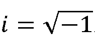
- Verfahren nach einem der Ansprüche 1 bis 9, wobei die Nutzdaten eine Direktzugriff, RACH, Nachricht aufweisen und wobei die RACH-Nachricht eine temporäre Funknetzkennung, RNTI, und/oder die Identität der drahtlosen Vorrichtung und/oder einen Verbindungsaufbau-Grund und/oder Uplink-Steuerinformationen, UCI, und/oder Strahlinformationen aufweist.
- Verfahren nach Anspruch 1, wobei das drahtlose Gerät einen inaktiven Funkressourcen-Steuerung, RRC, Zustand oder einen RRC-Leerlaufzustand aufweist und wobei die Nutzdaten die Identität der drahtlosen Vorrichtung und die Benutzerebenendaten aufweisen.
- Verfahren nach Anspruch 1 oder 2, das ferner aufweist:Spreizen von mehreren Eingangssymbolen, um mehrere Spreizsymbole zu erzeugen; undErzeugen der Nutzdaten durch Differenzcodieren der mehreren Spreizsymbole.
- Verfahren nach Anspruch 1 oder 2, das ferner aufweist:Differenzcodieren von mehreren Eingangssymbolen, um mehrere differenzcodierte Symbole zu erzeugen; undErzeugen der Nutzdaten durch Spreizen der mehreren differenzcodierten Symbole.
- Drahtlose Kommunikationsvorrichtung, die eine Einrichtung zum Ausführen des Verfahrens nach einem der Ansprüche 1 bis 13 aufweist.
Applications Claiming Priority (1)
| Application Number | Priority Date | Filing Date | Title |
|---|---|---|---|
| PCT/CN2019/071485 WO2020034577A1 (en) | 2019-01-11 | 2019-01-11 | Contention-based payload transmissions using differential coding |
Publications (3)
| Publication Number | Publication Date |
|---|---|
| EP3909367A1 EP3909367A1 (de) | 2021-11-17 |
| EP3909367A4 EP3909367A4 (de) | 2022-01-12 |
| EP3909367B1 true EP3909367B1 (de) | 2025-03-19 |
Family
ID=69524652
Family Applications (1)
| Application Number | Title | Priority Date | Filing Date |
|---|---|---|---|
| EP19849396.7A Active EP3909367B1 (de) | 2019-01-11 | 2019-01-11 | Konfliktbasierte nutzdatenübertragungen mittels differenzieller codierung |
Country Status (4)
| Country | Link |
|---|---|
| US (1) | US12047217B2 (de) |
| EP (1) | EP3909367B1 (de) |
| CN (1) | CN113303013B (de) |
| WO (1) | WO2020034577A1 (de) |
Families Citing this family (2)
| Publication number | Priority date | Publication date | Assignee | Title |
|---|---|---|---|---|
| WO2022216064A1 (ko) * | 2021-04-06 | 2022-10-13 | 엘지전자 주식회사 | 무선 통신 시스템에서 pusch를 송수신하는 방법 및 이를 위한 장치 |
| WO2025129645A1 (en) * | 2023-12-22 | 2025-06-26 | Qualcomm Incorporated | Block code design for ambient internet of things (iot) devices |
Family Cites Families (21)
| Publication number | Priority date | Publication date | Assignee | Title |
|---|---|---|---|---|
| JP2912123B2 (ja) * | 1993-07-22 | 1999-06-28 | 新日本製鐵株式会社 | 耐表面損傷性に優れた高強度・高靭性ベイナイト系レールの製造法 |
| US5754600A (en) * | 1994-08-29 | 1998-05-19 | Motorola, Inc. | Method and apparatus for optimum soft-decision viterbi decoding of convolutional-differential encoded QPSK data in coherent detection |
| JP3145003B2 (ja) * | 1995-03-23 | 2001-03-12 | 株式会社東芝 | 直交周波数分割多重伝送方式とその送信装置および受信装置 |
| US7590386B2 (en) * | 2002-04-18 | 2009-09-15 | Interdigital Technology Corporation | Method for control of contention-based wireless access |
| FI20065866A0 (fi) * | 2006-12-29 | 2006-12-29 | Nokia Corp | Tiedonsiirto matkaviestinjärjestelmässä |
| US8271687B2 (en) * | 2007-06-19 | 2012-09-18 | Cisco Technology, Inc. | Streaming network coding |
| US8315204B2 (en) * | 2009-07-06 | 2012-11-20 | Intel Corporation | Beamforming using base and differential codebooks |
| US8467480B2 (en) * | 2009-09-14 | 2013-06-18 | Qualcomm Incorporated | Combining decision metrics for decoding based on payload difference |
| US20130101063A1 (en) * | 2011-10-19 | 2013-04-25 | Nec Laboratories America, Inc. | Dft-based channel estimation systems and methods |
| US9923808B2 (en) * | 2012-10-09 | 2018-03-20 | Netscout Systems, Inc. | System and method for real-time load balancing of network packets |
| GB2514083A (en) * | 2013-02-11 | 2014-11-19 | Sony Corp | Data processing apparatus and method |
| GB2512392A (en) * | 2013-03-28 | 2014-10-01 | Sony Corp | Transmitter and method of transmitting |
| US20150195819A1 (en) * | 2014-01-06 | 2015-07-09 | Intel IP Corporation | Systems and methods for modulation and coding scheme selection and configuration |
| US10631287B2 (en) | 2014-09-26 | 2020-04-21 | Samsung Electronics Co., Ltd. | Method and apparatus for supporting multi-radio access technology |
| KR102257882B1 (ko) * | 2014-09-26 | 2021-05-28 | 삼성전자 주식회사 | 멀티 무선 접속 기술을 지원하는 방법 및 장치 |
| US9998185B2 (en) * | 2015-03-27 | 2018-06-12 | Newracom, Inc. | Aggregation methods and systems for multi-user MIMO or OFDMA operation |
| US10367677B2 (en) * | 2016-05-13 | 2019-07-30 | Telefonaktiebolaget Lm Ericsson (Publ) | Network architecture, methods, and devices for a wireless communications network |
| WO2017200562A1 (en) * | 2016-05-19 | 2017-11-23 | Intel Corporation | Higher layer design for control plane packet processing in fifth generation (5g)-wearable communication |
| US10425970B2 (en) * | 2016-09-30 | 2019-09-24 | Qualcomm Incorporated | Precoding management for random access procedures |
| US10693605B2 (en) * | 2016-09-30 | 2020-06-23 | Qualcomm Incorporated | RACH transmission using multiple ports |
| US9949298B1 (en) * | 2017-05-04 | 2018-04-17 | At&T Intellectual Property I, L.P. | Facilitating signaling and transmission protocols for enhanced beam management for initial access |
-
2019
- 2019-01-11 EP EP19849396.7A patent/EP3909367B1/de active Active
- 2019-01-11 CN CN201980088758.6A patent/CN113303013B/zh active Active
- 2019-01-11 WO PCT/CN2019/071485 patent/WO2020034577A1/en not_active Ceased
-
2021
- 2021-07-12 US US17/373,033 patent/US12047217B2/en active Active
Also Published As
| Publication number | Publication date |
|---|---|
| US12047217B2 (en) | 2024-07-23 |
| EP3909367A1 (de) | 2021-11-17 |
| WO2020034577A1 (en) | 2020-02-20 |
| US20210345417A1 (en) | 2021-11-04 |
| CN113303013B (zh) | 2024-04-16 |
| CN113303013A (zh) | 2021-08-24 |
Similar Documents
| Publication | Publication Date | Title |
|---|---|---|
| EP3804207B1 (de) | Overhead-verringerung und zuverlässigkeitserhöhungen für dl-steuersignalisierung | |
| US11700605B2 (en) | Transmission of UL control channels with dynamic structures | |
| EP3522471B1 (de) | Verfahren zum senden oder empfangen eines signals in einem drahtloskommunikationssystem und vorrichtung dafür | |
| US9949276B2 (en) | Signaling message transmission in a wireless communication network | |
| KR102765590B1 (ko) | 디스커버리 신호 및 채널의 타이밍 구성을 위한 방법 및 장치 | |
| EP2688226B1 (de) | Verfahren und vorrichtung zur kommunikation zwischen vorrichtungen | |
| US10469222B2 (en) | Method and MTC device for transmitting DMRS for uplink data demodulation | |
| US10244378B2 (en) | Method for selecting neighboring UE to perform D2D communication | |
| EP3447957B1 (de) | Verfahren und vorrichtung zur rückkopplung von kanalstatusinformationen | |
| US20240178969A1 (en) | Sounding reference signal transmissions for massive uplink transmitters | |
| US12047217B2 (en) | Contention-based payload transmissions using differential coding | |
| US11206653B2 (en) | Method for performing MM-based NOMA communication and device therefor | |
| US9960934B2 (en) | Channel estimation for FBMC modulation | |
| US11601318B2 (en) | Contention-based payload transmissions using differential coding | |
| US11963231B2 (en) | Transmitter-side processing of preambles and reference signals |
Legal Events
| Date | Code | Title | Description |
|---|---|---|---|
| STAA | Information on the status of an ep patent application or granted ep patent |
Free format text: STATUS: THE INTERNATIONAL PUBLICATION HAS BEEN MADE |
|
| PUAI | Public reference made under article 153(3) epc to a published international application that has entered the european phase |
Free format text: ORIGINAL CODE: 0009012 |
|
| STAA | Information on the status of an ep patent application or granted ep patent |
Free format text: STATUS: REQUEST FOR EXAMINATION WAS MADE |
|
| 17P | Request for examination filed |
Effective date: 20210811 |
|
| AK | Designated contracting states |
Kind code of ref document: A1 Designated state(s): AL AT BE BG CH CY CZ DE DK EE ES FI FR GB GR HR HU IE IS IT LI LT LU LV MC MK MT NL NO PL PT RO RS SE SI SK SM TR |
|
| REG | Reference to a national code |
Ref country code: DE Ref legal event code: R079 Free format text: PREVIOUS MAIN CLASS: H04W0072120000 Ipc: H04L0027260000 Ref country code: DE Ref legal event code: R079 Ref document number: 602019067573 Country of ref document: DE Free format text: PREVIOUS MAIN CLASS: H04W0072120000 Ipc: H04L0027260000 |
|
| A4 | Supplementary search report drawn up and despatched |
Effective date: 20211213 |
|
| RIC1 | Information provided on ipc code assigned before grant |
Ipc: H04W 76/27 20180101ALN20211207BHEP Ipc: H04L 27/34 20060101ALN20211207BHEP Ipc: H04L 27/20 20060101ALN20211207BHEP Ipc: H04L 27/12 20060101ALN20211207BHEP Ipc: H04L 5/00 20060101ALN20211207BHEP Ipc: H04L 27/26 20060101AFI20211207BHEP |
|
| DAV | Request for validation of the european patent (deleted) | ||
| DAX | Request for extension of the european patent (deleted) | ||
| STAA | Information on the status of an ep patent application or granted ep patent |
Free format text: STATUS: EXAMINATION IS IN PROGRESS |
|
| 17Q | First examination report despatched |
Effective date: 20230310 |
|
| GRAP | Despatch of communication of intention to grant a patent |
Free format text: ORIGINAL CODE: EPIDOSNIGR1 |
|
| STAA | Information on the status of an ep patent application or granted ep patent |
Free format text: STATUS: GRANT OF PATENT IS INTENDED |
|
| RIC1 | Information provided on ipc code assigned before grant |
Ipc: H04W 76/27 20180101ALN20241107BHEP Ipc: H04L 27/34 20060101ALN20241107BHEP Ipc: H04L 27/20 20060101ALN20241107BHEP Ipc: H04L 27/12 20060101ALN20241107BHEP Ipc: H04L 5/00 20060101ALN20241107BHEP Ipc: H04L 27/26 20060101AFI20241107BHEP |
|
| INTG | Intention to grant announced |
Effective date: 20241128 |
|
| GRAS | Grant fee paid |
Free format text: ORIGINAL CODE: EPIDOSNIGR3 |
|
| GRAA | (expected) grant |
Free format text: ORIGINAL CODE: 0009210 |
|
| STAA | Information on the status of an ep patent application or granted ep patent |
Free format text: STATUS: THE PATENT HAS BEEN GRANTED |
|
| AK | Designated contracting states |
Kind code of ref document: B1 Designated state(s): AL AT BE BG CH CY CZ DE DK EE ES FI FR GB GR HR HU IE IS IT LI LT LU LV MC MK MT NL NO PL PT RO RS SE SI SK SM TR |
|
| REG | Reference to a national code |
Ref country code: GB Ref legal event code: FG4D |
|
| REG | Reference to a national code |
Ref country code: CH Ref legal event code: EP |
|
| REG | Reference to a national code |
Ref country code: IE Ref legal event code: FG4D |
|
| REG | Reference to a national code |
Ref country code: DE Ref legal event code: R096 Ref document number: 602019067573 Country of ref document: DE |
|
| PG25 | Lapsed in a contracting state [announced via postgrant information from national office to epo] |
Ref country code: RS Free format text: LAPSE BECAUSE OF FAILURE TO SUBMIT A TRANSLATION OF THE DESCRIPTION OR TO PAY THE FEE WITHIN THE PRESCRIBED TIME-LIMIT Effective date: 20250619 |
|
| PG25 | Lapsed in a contracting state [announced via postgrant information from national office to epo] |
Ref country code: FI Free format text: LAPSE BECAUSE OF FAILURE TO SUBMIT A TRANSLATION OF THE DESCRIPTION OR TO PAY THE FEE WITHIN THE PRESCRIBED TIME-LIMIT Effective date: 20250319 |
|
| REG | Reference to a national code |
Ref country code: LT Ref legal event code: MG9D |
|
| PG25 | Lapsed in a contracting state [announced via postgrant information from national office to epo] |
Ref country code: NO Free format text: LAPSE BECAUSE OF FAILURE TO SUBMIT A TRANSLATION OF THE DESCRIPTION OR TO PAY THE FEE WITHIN THE PRESCRIBED TIME-LIMIT Effective date: 20250619 |
|
| PG25 | Lapsed in a contracting state [announced via postgrant information from national office to epo] |
Ref country code: HR Free format text: LAPSE BECAUSE OF FAILURE TO SUBMIT A TRANSLATION OF THE DESCRIPTION OR TO PAY THE FEE WITHIN THE PRESCRIBED TIME-LIMIT Effective date: 20250319 |
|
| PG25 | Lapsed in a contracting state [announced via postgrant information from national office to epo] |
Ref country code: LV Free format text: LAPSE BECAUSE OF FAILURE TO SUBMIT A TRANSLATION OF THE DESCRIPTION OR TO PAY THE FEE WITHIN THE PRESCRIBED TIME-LIMIT Effective date: 20250319 |
|
| PG25 | Lapsed in a contracting state [announced via postgrant information from national office to epo] |
Ref country code: GR Free format text: LAPSE BECAUSE OF FAILURE TO SUBMIT A TRANSLATION OF THE DESCRIPTION OR TO PAY THE FEE WITHIN THE PRESCRIBED TIME-LIMIT Effective date: 20250620 Ref country code: BG Free format text: LAPSE BECAUSE OF FAILURE TO SUBMIT A TRANSLATION OF THE DESCRIPTION OR TO PAY THE FEE WITHIN THE PRESCRIBED TIME-LIMIT Effective date: 20250319 |
|
| REG | Reference to a national code |
Ref country code: NL Ref legal event code: MP Effective date: 20250319 |
|
| REG | Reference to a national code |
Ref country code: AT Ref legal event code: MK05 Ref document number: 1777895 Country of ref document: AT Kind code of ref document: T Effective date: 20250319 |
|
| PG25 | Lapsed in a contracting state [announced via postgrant information from national office to epo] |
Ref country code: NL Free format text: LAPSE BECAUSE OF FAILURE TO SUBMIT A TRANSLATION OF THE DESCRIPTION OR TO PAY THE FEE WITHIN THE PRESCRIBED TIME-LIMIT Effective date: 20250319 |
|
| PG25 | Lapsed in a contracting state [announced via postgrant information from national office to epo] |
Ref country code: SE Free format text: LAPSE BECAUSE OF FAILURE TO SUBMIT A TRANSLATION OF THE DESCRIPTION OR TO PAY THE FEE WITHIN THE PRESCRIBED TIME-LIMIT Effective date: 20250319 |
|
| PG25 | Lapsed in a contracting state [announced via postgrant information from national office to epo] |
Ref country code: SM Free format text: LAPSE BECAUSE OF FAILURE TO SUBMIT A TRANSLATION OF THE DESCRIPTION OR TO PAY THE FEE WITHIN THE PRESCRIBED TIME-LIMIT Effective date: 20250319 |
|
| PG25 | Lapsed in a contracting state [announced via postgrant information from national office to epo] |
Ref country code: PT Free format text: LAPSE BECAUSE OF FAILURE TO SUBMIT A TRANSLATION OF THE DESCRIPTION OR TO PAY THE FEE WITHIN THE PRESCRIBED TIME-LIMIT Effective date: 20250721 Ref country code: ES Free format text: LAPSE BECAUSE OF FAILURE TO SUBMIT A TRANSLATION OF THE DESCRIPTION OR TO PAY THE FEE WITHIN THE PRESCRIBED TIME-LIMIT Effective date: 20250319 |
|
| PG25 | Lapsed in a contracting state [announced via postgrant information from national office to epo] |
Ref country code: IT Free format text: LAPSE BECAUSE OF FAILURE TO SUBMIT A TRANSLATION OF THE DESCRIPTION OR TO PAY THE FEE WITHIN THE PRESCRIBED TIME-LIMIT Effective date: 20250319 Ref country code: PL Free format text: LAPSE BECAUSE OF FAILURE TO SUBMIT A TRANSLATION OF THE DESCRIPTION OR TO PAY THE FEE WITHIN THE PRESCRIBED TIME-LIMIT Effective date: 20250319 |
|
| PG25 | Lapsed in a contracting state [announced via postgrant information from national office to epo] |
Ref country code: AT Free format text: LAPSE BECAUSE OF FAILURE TO SUBMIT A TRANSLATION OF THE DESCRIPTION OR TO PAY THE FEE WITHIN THE PRESCRIBED TIME-LIMIT Effective date: 20250319 |
|
| PG25 | Lapsed in a contracting state [announced via postgrant information from national office to epo] |
Ref country code: CZ Free format text: LAPSE BECAUSE OF FAILURE TO SUBMIT A TRANSLATION OF THE DESCRIPTION OR TO PAY THE FEE WITHIN THE PRESCRIBED TIME-LIMIT Effective date: 20250319 Ref country code: EE Free format text: LAPSE BECAUSE OF FAILURE TO SUBMIT A TRANSLATION OF THE DESCRIPTION OR TO PAY THE FEE WITHIN THE PRESCRIBED TIME-LIMIT Effective date: 20250319 |
|
| PG25 | Lapsed in a contracting state [announced via postgrant information from national office to epo] |
Ref country code: RO Free format text: LAPSE BECAUSE OF FAILURE TO SUBMIT A TRANSLATION OF THE DESCRIPTION OR TO PAY THE FEE WITHIN THE PRESCRIBED TIME-LIMIT Effective date: 20250319 |
|
| PG25 | Lapsed in a contracting state [announced via postgrant information from national office to epo] |
Ref country code: SK Free format text: LAPSE BECAUSE OF FAILURE TO SUBMIT A TRANSLATION OF THE DESCRIPTION OR TO PAY THE FEE WITHIN THE PRESCRIBED TIME-LIMIT Effective date: 20250319 |
|
| PG25 | Lapsed in a contracting state [announced via postgrant information from national office to epo] |
Ref country code: IS Free format text: LAPSE BECAUSE OF FAILURE TO SUBMIT A TRANSLATION OF THE DESCRIPTION OR TO PAY THE FEE WITHIN THE PRESCRIBED TIME-LIMIT Effective date: 20250719 |
|
| REG | Reference to a national code |
Ref country code: DE Ref legal event code: R097 Ref document number: 602019067573 Country of ref document: DE |
|
| PGFP | Annual fee paid to national office [announced via postgrant information from national office to epo] |
Ref country code: GB Payment date: 20251204 Year of fee payment: 8 |
|
| PG25 | Lapsed in a contracting state [announced via postgrant information from national office to epo] |
Ref country code: DK Free format text: LAPSE BECAUSE OF FAILURE TO SUBMIT A TRANSLATION OF THE DESCRIPTION OR TO PAY THE FEE WITHIN THE PRESCRIBED TIME-LIMIT Effective date: 20250319 |
|
| PGFP | Annual fee paid to national office [announced via postgrant information from national office to epo] |
Ref country code: FR Payment date: 20251208 Year of fee payment: 8 |
|
| PLBE | No opposition filed within time limit |
Free format text: ORIGINAL CODE: 0009261 |
|
| STAA | Information on the status of an ep patent application or granted ep patent |
Free format text: STATUS: NO OPPOSITION FILED WITHIN TIME LIMIT |
|
| REG | Reference to a national code |
Ref country code: CH Ref legal event code: L10 Free format text: ST27 STATUS EVENT CODE: U-0-0-L10-L00 (AS PROVIDED BY THE NATIONAL OFFICE) Effective date: 20260128 |
|
| 26N | No opposition filed |
Effective date: 20251222 |
|
| PGFP | Annual fee paid to national office [announced via postgrant information from national office to epo] |
Ref country code: DE Payment date: 20251203 Year of fee payment: 8 |