EP3909438B1 - Übergabeeinheit - Google Patents
Übergabeeinheit Download PDFInfo
- Publication number
- EP3909438B1 EP3909438B1 EP21171137.9A EP21171137A EP3909438B1 EP 3909438 B1 EP3909438 B1 EP 3909438B1 EP 21171137 A EP21171137 A EP 21171137A EP 3909438 B1 EP3909438 B1 EP 3909438B1
- Authority
- EP
- European Patent Office
- Prior art keywords
- semi
- products
- stop surfaces
- conveyor
- seats
- Prior art date
- Legal status (The legal status is an assumption and is not a legal conclusion. Google has not performed a legal analysis and makes no representation as to the accuracy of the status listed.)
- Active
Links
Images


Classifications
-
- A—HUMAN NECESSITIES
- A24—TOBACCO; CIGARS; CIGARETTES; SIMULATED SMOKING DEVICES; SMOKERS' REQUISITES
- A24C—MACHINES FOR MAKING CIGARS OR CIGARETTES
- A24C5/00—Making cigarettes; Making tipping materials for, or attaching filters or mouthpieces to, cigars or cigarettes
- A24C5/32—Separating, ordering, counting or examining cigarettes; Regulating the feeding of tobacco according to rod or cigarette condition
- A24C5/322—Transporting cigarettes during manufacturing
- A24C5/326—Transporting cigarettes during manufacturing with lateral transferring means
-
- A—HUMAN NECESSITIES
- A24—TOBACCO; CIGARS; CIGARETTES; SIMULATED SMOKING DEVICES; SMOKERS' REQUISITES
- A24C—MACHINES FOR MAKING CIGARS OR CIGARETTES
- A24C5/00—Making cigarettes; Making tipping materials for, or attaching filters or mouthpieces to, cigars or cigarettes
- A24C5/32—Separating, ordering, counting or examining cigarettes; Regulating the feeding of tobacco according to rod or cigarette condition
- A24C5/322—Transporting cigarettes during manufacturing
- A24C5/327—Construction details of the cigarette transport drum
Definitions
- This invention relates to the technical sector of machines and processing processes of the tobacco industry.
- this invention relates to a transfer unit for transferring rod-shaped semi-products for a processing machine of the tobacco industry, as well as the processing machine itself.
- This invention also relates to the method for preparing the transfer unit to adapt it to operate following a format changeover of the semi-products to be transferred and to a respective method for the transfer of rod-shaped semi-products in a processing machine of the tobacco industry.
- That problem is accentuated if the same processing machine, or at least one of its parts, must be able to be prepared for processing semi-products which have different features, particularly in terms of dimensions.
- the prior art uses a "format changeover" procedure in which one or more elements of the processing machine are replaced to make them suitable for operating correctly with the specifications of the new semi-product.
- the processing machine typically comprises a conveyor assembly configured to receive and transversely convey the multisegment semi-products and a releasing assembly configured to transfer them from the conveyor assembly to a forming beam for axially-longitudinally conveying the semi-products in such a way as to form a continuous rod.
- the releasing assembly is at least partly replaced and slides movable thanks to suitable motors are used to move the entire conveyor assembly.
- This system involves a large number of movements and does not allow a continuous machine front plane, with consequent risks of intrusion by products inside the base itself and noise emission.
- the technical purpose which forms the basis of this invention is to propose a transfer unit for semi-products which overcomes at least some of the above-mentioned disadvantages of the prior art.
- the aim of this invention is to provide a transfer unit which allows the processing machine in which it is installed to be adapted in a simple and efficient way for processing semi-products having different formats and/or features.
- this invention shows a transfer unit for transferring rod-shaped semi-products for a processing machine of the tobacco industry which comprises a conveyor assembly, a releasing assembly and resetting device.
- the conveyor assembly comprises one or more conveyor drums, each of which has a plurality of seats configured to receive and transversely convey a succession of rod-shaped semi-products.
- At least some of the seats of at least one conveyor drum are associated with respective stop surfaces which define an axial abutment for positioning a respective rod-shaped semi-product in the seat.
- the releasing assembly is configured to transfer the succession of semi-products from the conveyor assembly to a forming beam and is configurable to transfer semi-products of different formats as a function of a format changeover in the processing machine.
- the resetting device defines the stop surfaces and acts in conjunction with at least one conveyor drum to vary the axial position of the stop surfaces along the axis of rotation of that conveyor drum as a function of a format changeover in the processing machine.
- the transfer unit allows the processing machine to be prepared in a particularly high-performance way for operating with semi-products of different formats, by modifying the position of the stop surfaces which allow definition of the dimensions and/or positioning of the seats inside which the semi-products are received and conveyed.
- This invention also relates to a processing machine, specifically a processing machine of the tobacco industry which comprises a unit according to this invention.
- This invention also relates to a method for performing the format changeover in a conveying unit for semi-products of the tobacco industry, specifically multisegment semi-products or multisegment filters which comprises the following steps:
- the method described here allows optimization of the format changeover processes in a processing machine of the tobacco industry, by simply performing an adjustment/replacement of the resetting device without the need to modify the operating conditions of all of the elements upstream/downstream of it.
- This invention also relates to a method for transferring rod-shaped semi-products, specifically multisegment semi-products or multisegment filters, in a processing machine of the tobacco industry, which comprises a step of transferring a succession of semi-products by means of a unit according to this invention and a step of changing format performed according to the format changeover method according to this invention.
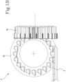
- the unit 1 described herein is configured to transfer rod-shaped semi-products in a processing machine 100 of the tobacco industry and comprises a conveyor assembly 2, a releasing assembly 3 and a resetting device 4.
- the conveyor assembly 2 in turn comprises one or more conveyor drums 5, each of which has a plurality of seats 5a configured to receive and transversely convey a succession of rod-shaped semi-products.
- At least some of the seats 5a, preferably all of the seats, of at least one of the conveyor drums 5 are associated with respective stop surfaces 6, which define an axial abutment for positioning a respective rod-shaped semi-product in each seat 5a.
- the seats 5a have an elongate shape which preferably extends between the opposite faces of the respective conveyor drum 5, in which the stop surface 6 defines a stop against which one end of the semi-product will abut during use of the unit 1.
- the releasing assembly 3 is configured to transfer the succession of semi-products from the conveyor assembly 2 to a forming beam "T".
- the forming beam "T" is of the type configured to axially-longitudinally convey the semi-products, in such a way as to form a continuous rod.
- the releasing assembly 3 is configurable to transfer semi-products of different formats as a function of a format changeover in the processing machine 100.
- the releasing assembly 3 comprises a drum with orientable arms 3a and a spider conveyor 3b.
- the orientable arms of the drum with orientable arms 3a are configured to receive the succession of semi-products from the conveyor assembly 3 and to transfer them transversely.
- the orientable arms are also replaceable in such a way as to be able to adapt them at a format changeover in the processing machine 100.
- the spider conveyor 3b is configured to receive the succession of semi-products from the orientable arms and to transfer them to the forming beam "T" and it can be replaced to perform the format changeover.
- the spider conveyor 3b can be totally replaced and/or repositioned relative to a supporting frame of the processing machine 100, in such a way that the set-down point in which the spider conveyor 3b releases the semi-products on the forming beam "T" remains unchanged, even and particularly following a format changeover in the processing machine 100.
- the resetting device 4 defines the stop surfaces 6 and acts in conjunction with at least one respective conveyor drum 5 of the conveyor assembly 2 to vary the axial position of the stop surfaces 6 along the axis of rotation of that specific conveyor drum 5, as a function of a format changeover in the processing machine 100.
- the resetting device 4 modifies the axial position of the stop surfaces 6 as a function of the specific format of the semi-products which the unit 1 must transfer.
- stop surfaces 6 substantially define an axial dimension of the seats 5a and a variation in their position relative to the transfer drum 5 to which they are coupled allows modification of the effective position in which the semi-product received from the transfer drum 5 will effectively be positioned, so as to adapt it to the corresponding modification of the subsequent drum with orientable arms 3°.
- the variation in the format of the semi-products to be processed in the processing machine 100 (which involves a variation of the respective length) will be compensated for by a movement of the stop surfaces 6, allowing the unit 1 to be adapted in a simple and efficient way for transferring the new format, without the need to perform a complex and onerous operation for replacing/moving all of the components of the processing machine 100.
- the action of the resetting device 4 allows modification of the structure of the seats 5a in such a way as to define a modifiable interface portion of the processing machine 100 which allows a correct transfer of the articles from the processes/stations upstream of the resetting device 4 itself to those downstream.
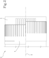
- the resetting device 4 comprises a plurality of fingers 4a associated with respective seats 5a of the conveyor assembly 2 and each of which defines a respective stop surface 6.
- the fingers 4a associated with the same conveyor drum 5 are integral with each other through a supporting member 4b, which is rotationally synchronous with the respective conveyor drum 5 and rotatable about its axis of rotation "X".
- the supporting member 4b may be made in the form of a disc, a plate or a ring, preferably using metal materials.
- the fingers 4a are made as one, that is to say, monolithically, with the supporting member 4b, for example extending away from the latter along a line perpendicular to a lying plane of the supporting member 4b.
- the fingers 4a are slidably inserted into the seats 5a, therefore the variation in the position of the stop surfaces 6 is obtained by an axial adjustment movement performed by that supporting member 4b along the axis of rotation of the conveyor drum 5 to which the resetting device 4 is coupled.
- the fingers 4a may be replaceable so that different axial positions of the stop surfaces 6 in the respective seats 5a can be obtained, in particular by totally replacing the supporting member 4b.
- the stop surfaces 6 can be associated with all of the seats 5a of the same conveyor drum 5, in particular of a single conveyor drum 5.
- the stop surfaces 6 can be associated with multiple different conveyor drums 5.
- the stop surfaces 6 can be associated with each seat 5a of each conveyor drum 5, or be associated only with some seats 5a of each conveyor drum 5.
- stop surfaces 6 can be defined and divided into groups having different features.
- the stop surfaces 6 can be defined by a plurality of first stop surfaces 6a and second stop surfaces 6b having different structure and/or axial position.
- the first and second stop surfaces 6a, 6b have different axial positions defining an alternating trend in the stop surfaces about the axis of the drum. That aspect is particularly advantageous if the unit 1 is used in a processing machine 100 configured to make and/or process multisegment semi-products which have different lengths.
- the axial staggering between the first and second stop surfaces 6a, 6b can be selected as a function of the difference in length between the respective groups of segments to create the desired lateral alignment or centring.
- the different groups of stop surfaces 6 can be associated with the same conveyor drum 5, as shown in the embodiment in Figures 3A and 3B , or with different conveyor drums 5 if the conveyor assembly 2 comprises more than one of them.
- the resetting device 4 may comprise a single supporting member 4b having multiple groups of fingers 4a, alternating with each other, having different dimensions and adapted to define respective pluralities of stop surfaces or, alternatively, the resetting device 4 may comprise a plurality of supporting members 4b each having respective fingers 4a with specific shapes and/or dimensions and associated with respective conveyor drums 5 (in particular, the plurality of first stop surfaces 6a may be associated with a first conveyor drum 5 and the plurality of second stop surfaces 6b may be associated with a second conveyor drum 5), in such a way as to define on each conveyor drum 5 respective stop surfaces 6.
- the resetting device 4 may also comprise more than two supporting members 4b each having one or more groups of fingers 4a adapted to define respective pluralities of stop surfaces 6, for example in the case of successions of groups of segments having at least three different lengths.
- those groups are adjustable independently of each other, in particular, when those groups of fingers 4a are associated with respective conveyor drums 5 which are separate and/or with different supporting members 4b.
- the unit may also comprise pushing means operating at least on the seats 5a associated with respective stop surfaces 6, in such a way as to apply an axial pushing action on the semi-products housed in them towards the stop surface 6.
- the pushing means allow the semi-products to be firmly abutted against the stop surfaces, which therefore act as stops for the axial sliding of the semi-products inside the respective seats 5a under the action of the pushing means.
- the pushing means comprise mechanical pushing means, preferably consisting of a plurality of pushers adapted to engage and push one end of respective semi-products axially towards the stop surfaces 6.
- the pushing means comprise pneumatic pushing means, preferably comprising at least one blower adapted to blow a jet of air at one end of respective semi-products, thereby pushing them axially towards the stop surfaces 6.
- the pushing means may comprise a combination of mechanical pushing means and pneumatic pushing means, associated with respective seats 5a as a function of the specific features of the semi-products to be conveyed in those seats 5a.
- this invention achieves the preset aims, overcoming the disadvantages of the prior art by providing a transfer unit 1 which allows the processing machine 100 in which it is installed to be rapidly and efficiently adapted to operate with semi-products of different formats.
- the presence of the resetting device 4 makes the unit 1 capable of creating an efficient interface between the upstream processing stations and the forming beam, allowing a format changeover to be performed in the processing machine 100 without the need to totally structurally/functionally modify even some of the elements of the processing machine 100 located upstream and downstream of the unit 1.
- This invention also relates to a processing machine 100 for making multisegment semi-products of the tobacco industry.
- the processing machine 100 is configured to make multisegment filters.
- the processing machine 100 comprises at least one feed line 101, as shown in the accompanying figures, configured to feed segments made of material of the tobacco industry which are made starting from a plurality of pieces supplied by means of a hopper 101a, which are appropriately divided into a plurality of segments in a cutting station 101b and are then transferred, if necessary after having been further processed, to the transfer unit 1.
- the feed line 101 may also be configured if necessary to feed segments fed individually and not obtained by cutting respective rods, for example tubular segments.
- the processing machine 100 comprises a plurality of feed lines 101 for segments having different properties and an assembling device configured to receive respective segments from those lines 101 assembling the segments into at least two periodic alternating successions of semi-products preferably having different axial dimensions, feeding them transversely.
- each feed line 101 comprises a respective hopper 101a adapted to contain pieces having specific properties and a respective cutting station 101b in which those pieces are divided to make segments in turn having specific properties/formats.
- the processing machine 100 also comprises, inside the assembling device or downstream of it, a transfer unit 1 made according to what is described above.
- processing machine 100 allows the disadvantages of the prior art to be overcome, since, thanks to the transfer unit 1, it is easily and rapidly adaptable to operate with segments of different formats.
- This invention also relates to a method for performing the format changeover in a transfer unit 1 for transferring semi-products of the tobacco industry, specifically multisegment semi-products or multisegment filters.
- the method applies to a unit 1 as described above.
- a releasing assembly 3 is prepared as a function of a specific format of the semi-products.
- the releasing assembly is a releasing assembly made according to what is described above, specifically a releasing assembly 3 which comprises a drum with orientable arms 3a and a spider conveyor 3b.
- preparation of the releasing assembly 3 occurs with a replacement and/or movement of the spider conveyor 3b, in such a way as to keep a fixed releasing point for the semi-products relative to the forming beam "T", and a corresponding replacement and/or variation of the orientable arms.
- the resetting device 4 is adjusted or replaced in such a way as to set the axial position of the stop surfaces 6 associated with the seats 5a as a function of the specific format of the semi-products to be transferred, specifically as a function of the transfer elements of the releasing assembly 3.
- an adjustment or replacement of the resetting device 4 is performed which allows modification of the position of the stop surfaces 6, causing a structural variation of the seats 5a in such a way as to adapt them to conveying the semi-products, interfacing in the optimum way the releasing assembly 3 and the processing stations located immediately upstream of the unit 1.
- At least one drum of the conveyor assembly 2, disposed upstream of the resetting device 4 and specifically at least the drum immediately upstream of the drum associated with the resetting device 4, is not modified or replaced or subjected to movement.
- the presence and the operation of the resetting device 4 allows a format changeover procedure to be performed without the need to move, modify and/or replace at least one of the drums which are located upstream of the resetting device 4 itself, since by operating directly on the latter it is possible to create an interface which guarantees correct movement of the semi-products from the processes and from the processing stations upstream to those downstream of the unit 1.
- the resetting device according to what is described above may be used both for transferring monolithic semi-products (single segments) and multisegment groups. Moreover, the resetting device according to what is described above may be used both for feeding segments or multisegment groups having the same length (therefore defining a single transversal succession) or for feeding segments or multisegment groups having different lengths, therefore defining an alternating and repeated succession of two or more segments or multisegment groups.
- the stop surfaces 6; 6a, 6b are made as one with the shell of the respective drum. In this situation, to perform the format changeover it is sufficient to replace only the drum having the stop surfaces 6; 6a, 6b.
- This invention also relates to a method for transferring rod-shaped semi-products, specifically multisegment semi-products or multisegment filters, in a processing machine 100 of the tobacco industry.
- That method comprises transferring a succession of semi-products by means of a unit 1 according to what is described above which has been subjected to a preparation step using a method for performing the format changeover according to this invention.
- the methods presented herein allow optimization of the processes for processing semi-products of the tobacco industry, providing a particularly efficient procedure for adapting the processing machine 100 to operate with semi-products of different formats.
Landscapes
- Manufacturing Of Cigar And Cigarette Tobacco (AREA)
Claims (17)
- Übergabeeinheit zur Übergabe von stabförmigen Halbfertigprodukten für eine Verarbeitungsmaschine (100) der Tabakindustrie, umfassend:- eine Fördereranordnung (2), umfassend eine oder mehrere Fördertrommeln (5), wobei eine jede Fördertrommel (5) eine Vielzahl von Aufnahmen (5a) aufweist, die ausgelegt sind, um eine Abfolge von stabförmigen Halbfertigprodukten aufzunehmen und quer zu fördern, wobei mindestens einige der Aufnahmen (5a) von mindestens einer Fördertrommel (5) mit jeweiligen Stoppoberflächen (6) assoziiert sind, die einen Axialanschlag zur Positionierung eines jeweiligen stabförmigen Halbfertigprodukts in der jeweiligen Aufnahme (6) definieren;- eine Freigabeanordnung (3), die ausgelegt ist, um die Abfolge von Halbfertigprodukten von der Fördereranordnung (2) an einen Formungsbalken (T) zu übergeben, um die Halbfertigprodukte längsseitig axial so zu fördern, dass ein durchgehender Stab geformt wird, wobei die Freigabeanordnung (3) auslegbar ist, um Halbfertigprodukte unterschiedlicher Formate abhängig von einer Formatumstellung in der Verarbeitungsmaschine (100) zu übergeben;wobei die Einheit dadurch gekennzeichnet ist, dass sie eine Rückstellvorrichtung (4) umfasst, die die Stoppoberflächen (6) definiert, wobei die Rückstellvorrichtung (4) gemeinsam mit mindestens einer jeweiligen Fördertrommel (5) der Fördereranordnung (2) arbeitet, um die axiale Position der Stoppoberflächen (6) entlang der Rotationsachse (X) der Fördertrommel (5) abhängig von einer Formatumstellung in der Verarbeitungsmaschine (100) zu variieren.
- Einheit nach Anspruch 1, wobei die Rückstellvorrichtung (4) eine Vielzahl von Fingern (4a) umfasst, die mit jeweiligen Aufnahmen (5a) der Fördereranordnung (2) assoziiert sind, und von denen ein jeder eine jeweilige Stoppoberfläche (6) definiert.
- Einheit nach Anspruch 2, wobei die Finger (4a), die mit der gleichen Fördertrommel (5) assoziiert sind, mittels eines Stützelements (4b) fest miteinander verbunden und vorzugsweise in einem Stück mit dem Stützelement (4b) ausgebildet sind, wobei das Stützelement (4b) rotatorisch synchron mit der jeweiligen Fördertrommel (5) und um die Rotationsachse (X) der Fördertrommel (5) drehbar ist.
- Einheit nach Anspruch 2 oder 3, wobei die Finger (4a) verschiebbar entlang der Aufnahmen (5a) insbesondere durch eine axiale Justierbewegung, die vom Stützelement (4b) entlang der Rotationsachse (X) der Fördertrommel (5) durchgeführt wird, bewegbar sind.
- Einheit nach Anspruch 2 oder 3, wobei die Finger (4a) austauschbar sind, sodass verschiedene axiale Positionen der Stoppoberflächen (6) in den jeweiligen Aufnahmen (5a) erhalten werden können, insbesondere durch den völligen Austausch des Stützelements (4b).
- Einheit nach einem oder mehreren der Ansprüche 3 bis 5, wobei das Stützelement (4b) die Form einer Scheibe oder Platte aufweist, vorzugsweise bestehend aus Metall und noch bevorzugter monolithisch mit den Fingern (4a) ausgebildet.
- Einheit nach einem oder mehreren der vorhergehenden Ansprüche, zudem umfassend Schiebemittel, die zumindest auf den Aufnahmen (5a) arbeiten, die mit jeweiligen Stoppoberflächen (6) assoziiert sind, um eine axiale Schubwirkung auf die in den Aufnahmen (5a) untergebrachten Halbfertigprodukte hinführend zur Stoppoberfläche (6) auszuüben.
- Einheit nach Anspruch 7, wobei die Schiebemittel mechanische Schiebemittel umfassen, die vorzugsweise eine Vielzahl von Schiebern umfassen, die dazu bestimmt sind, mit einem Ende jeweiliger Halbfertigprodukte in Eingriff zu gelangen und diese axial hinführend zu den Stoppoberflächen (6) zu schieben.
- Einheit nach Anspruch 7, wobei die Schiebemittel pneumatische Schiebemittel umfassen, die vorzugsweise mindestens ein Gebläse umfassen, das dazu bestimmt ist, einen Luftstrahl an einem Ende jeweiliger Halbfertigprodukte zu blasen, wodurch die Halbfertigprodukte axial hinführend zu den Stoppoberflächen (6) geschoben werden.
- Einheit nach einem oder mehreren der vorhergehenden Ansprüche, wobei die Stoppoberflächen (6) mit allen Aufnahmen (5a) der gleichen Fördertrommel (5) insbesondere einer einzelnen Fördertrommel (5) assoziiert sind.
- Einheit nach einem oder mehreren der vorhergehenden Ansprüche, wobei die Stoppoberflächen (6) durch eine Vielzahl von ersten Stoppoberflächen (6a) definiert sind, die mit einer Vielzahl von zweiten Stoppoberflächen (6b) abgewechselt sind, und wobei die ersten Stoppoberflächen (6a) und die zweiten Stoppoberflächen (6b) in jeweiligen Ebenen liegen, die parallel zueinander und beabstandet entlang der Achse der Fördertrommel (5) angeordnet sind, sodass verschiedene axiale Positionen der Halbfertigprodukte in den jeweiligen Aufnahmen (5a) definiert werden.
- Einheiten nach einem oder mehreren der Ansprüche 1 bis 10, wobei die Stoppoberflächen (6) durch eine Vielzahl von ersten Stoppoberflächen (6a) definiert sind, die mit einer ersten Fördertrommel (5) assoziiert sind, und eine Vielzahl von zweiten Stoppoberflächen (6b), die mit einer zweiten Fördertrommel (5) assoziiert sind, wobei die ersten und die zweiten Stoppoberflächen (6a, 6b) vorzugsweise unabhängig voneinander axial justierbar sind.
- Einheit nach einem oder mehreren der vorhergehenden Ansprüche, wobei die Freigabeanordnung (3) Folgendes umfasst:- eine Trommel (3a) mit verstellbaren Armen, die ausgelegt ist, um die Abfolge von Halbfertigprodukten von der Fördereranordnung (2) zu erhalten und die Halbfertigprodukte quer zu übergeben, wobei die verstellbaren Arme austauschbar sind, um eine Formatumstellung durchzuführen;- eine Förderspinne (3b), die ausgelegt ist, um die Abfolge von Halbfertigprodukten von den verstellbaren Armen zu erhalten und die Halbfertigprodukte an den Formungsbalken (T) durch eine translatorische Bewegung zu übergeben, die mindestens eine axiale Komponente aufweist, wobei die Förderspinne (3b) austauschbar ist, um eine Formatumstellung durchzuführen.
- Maschine zur Herstellung von aus mehreren Segmenten bestehenden Halbfertigprodukten der Tabakindustrie, insbesondere von aus mehreren Segmenten bestehenden Filtern, umfassend eine Vielzahl von Zuführungslinien zum Zuführen von Segmenten mit unterschiedlichen Eigenschaften und eine Zusammensetzungsvorrichtung, die ausgelegt ist, um jeweilige Segmente von den Zuführungslinien zu erhalten und die Segmente zu mindestens zwei periodisch abwechselnden Abfolgen von Halbfertigprodukten zusammenzusetzen, aufweisend vorzugsweise unterschiedliche axiale Abmessungen, wobei die Zuführungslinien und die Zusammensetzungsvorrichtung ausgelegt sind, um die Segmente quer zuzuführen, und wobei die Maschine in der Zusammensetzungsvorrichtung oder nach der Zusammensetzungsvorrichtung eine Übergabeeinheit nach einem oder mehreren der vorhergehenden Ansprüche umfasst.
- Verfahren zur Durchführung einer Formatumstellung bei einer Übergabeeinheit zum Übergeben von Halbfertigprodukten der Tabakindustrie, insbesondere von aus mehreren Segmenten bestehenden Halbfertigprodukten oder aus mehreren Segmenten bestehenden Filtern, nach einem oder mehreren der Ansprüche 1 bis 13, umfassend die folgenden Schritte:- Vorbereiten einer Freigabeanordnung (3) nach einem oder mehreren der vorhergehenden Ansprüche, insbesondere einer Freigabeanordnung (3) nach Anspruch 13;- Justieren oder Austauschen der Rückstellvorrichtung (4) zum Einstellen der axialen Position der Stoppoberflächen (6) abhängig vom spezifischen Format der zu übergehenden Halbfertigprodukte, insbesondere abhängig von den verstellbaren Armen (3a) der Trommel mit verstellbaren Armen (3a).
- Formatumstellungsverfahren nach Anspruch 15, wobei mindestens eine Trommel der Fördereranordnung (2), die vor der Rückstellvorrichtung (4) angeordnet ist, nicht geändert oder ausgetauscht oder einer Bewegung oder Positionsänderung der Stoppoberflächen der jeweiligen Aufnahmen für die stabförmigen Halbfertigprodukte unterzogen wird.
- Verfahren zur Übergabe von stabförmigen Halbfertigprodukten, insbesondere aus mehreren Segmenten bestehenden Halbfertigprodukten oder aus mehreren Segmenten bestehenden Filtern, in einer Verarbeitungsmaschine (100) der Tabakindustrie, umfassend einen Schritt zum Übergeben einer Abfolge von Halbfertigprodukten mittels einer Einheit nach einem oder mehreren der Ansprüche 1 bis 13 und einen Schritt zur Formatumstellung, der nach Anspruch 15 oder 16 durchgeführt wird.
Applications Claiming Priority (1)
| Application Number | Priority Date | Filing Date | Title |
|---|---|---|---|
| IT202000010621 | 2020-05-12 |
Publications (2)
| Publication Number | Publication Date |
|---|---|
| EP3909438A1 EP3909438A1 (de) | 2021-11-17 |
| EP3909438B1 true EP3909438B1 (de) | 2024-04-10 |
Family
ID=71784532
Family Applications (1)
| Application Number | Title | Priority Date | Filing Date |
|---|---|---|---|
| EP21171137.9A Active EP3909438B1 (de) | 2020-05-12 | 2021-04-29 | Übergabeeinheit |
Country Status (2)
| Country | Link |
|---|---|
| EP (1) | EP3909438B1 (de) |
| PL (1) | PL3909438T3 (de) |
Family Cites Families (5)
| Publication number | Priority date | Publication date | Assignee | Title |
|---|---|---|---|---|
| DE10146019A1 (de) * | 2001-09-18 | 2003-04-03 | Hauni Maschinenbau Ag | Einrichtung zum Zusammenstellen von Gruppen von Filtersegmenten zur Herstellung von Multisegmentfiltern der tabakverarbeitenden Industrie und Muldentrommel |
| DE102009041318A1 (de) * | 2009-09-15 | 2011-03-31 | Hauni Maschinenbau Ag | Einlegen von Filtersegmenten in Filterstränge |
| DE102011006025B3 (de) * | 2011-03-24 | 2012-07-19 | Hauni Maschinenbau Ag | Herstellung von Filterstopfen bzw. von Filterzigaretten |
| DE102013210634A1 (de) * | 2013-06-07 | 2014-12-11 | Hauni Maschinenbau Ag | Schiebetrommel für eine Maschine der Tabak verarbeitenden Industrie |
| DE102018104957A1 (de) * | 2018-03-05 | 2019-09-05 | Hauni Maschinenbau Gmbh | Schiebetrommel der Tabak verarbeitenden Industrie |
-
2021
- 2021-04-29 EP EP21171137.9A patent/EP3909438B1/de active Active
- 2021-04-29 PL PL21171137.9T patent/PL3909438T3/pl unknown
Also Published As
| Publication number | Publication date |
|---|---|
| EP3909438A1 (de) | 2021-11-17 |
| PL3909438T3 (pl) | 2024-06-17 |
Similar Documents
| Publication | Publication Date | Title |
|---|---|---|
| JP5635785B2 (ja) | たばことフィルタの製品ロッド製造機と協働する搬送システム及び搬送システムの中でたばことフィルタの製品ロッドを搬送する方法 | |
| KR101334003B1 (ko) | 타이어 구성 요소 제조 조립체 및 타이어 구성 요소 제조 방법 | |
| EP3183073A1 (de) | Vorrichtung und verfahren zum transport von vorformlingen im bereich einer blasmaschine | |
| EP2132028B1 (de) | Schneidegerät | |
| EP3322309B1 (de) | Verfahren und vorrichtung zur verschiebung von stabförmigen artikeln und vorrichtung zur verschiebung von stabförmigen artikeln | |
| EP3909438B1 (de) | Übergabeeinheit | |
| US10342252B2 (en) | Apparatus for centring of a rod-like article or a rod-like article group | |
| EP3501303B1 (de) | Vorrichtung zur herstellung von mehrsegmentstäben für produkte in der tabakindustrie | |
| CN110198826B (zh) | 具有屏蔽面板的用于加热塑料型坯的设备 | |
| EP3376883A1 (de) | Zentriervorrichtung für stangenförmige artikel der tabakindustrie | |
| EP2382146B2 (de) | Förderer für zu verarbeitende behälter, z. b. flaschen, sowie für verarbeitete behälter für arbeitsmaschinen des typs mit drehkarussell | |
| CN112399802A (zh) | 用于制造烟草加工工业的棒状产品的方法和装置 | |
| EP3868225B1 (de) | Einheit zur axialen positionierung, insbesondere zentrierung, für maschinen zur herstellung von mehrfachfiltern | |
| US9862549B2 (en) | Transfer method and transferring apparatus for transferring rod-shaped article | |
| CN108135252B (zh) | 用于烟草行业的条状制品的定心装置 | |
| CN104837617B (zh) | 用于传送扁平工件的方法和装置 | |
| EP3119216B1 (de) | Verfahren zur herstellung von rauchartikeln | |
| KR20240046562A (ko) | 담배 가공 산업용 이송 드럼 | |
| EP4480328B1 (de) | Schiebetrommel der tabak verarbeitenden industrie und verfahren zu deren betrieb | |
| EP4161297B1 (de) | Verfahren und vorrichtung zur herstellung von mehrsegmentartikeln | |
| EP3413854B1 (de) | Einheit zum zuführen von seitenklappen eines absorbierenden hygieneartikels und verfahren zum formatwechsel der zuführeinheit | |
| EP4374713A1 (de) | Vorrichtung und verfahren zur herstellung von mehrsegmentartikeln | |
| EP4159392A1 (de) | Vorrichtung und verfahren zum schneiden einer röhrenförmigen pappstange | |
| EP3263080B1 (de) | Transportverfahren und -vorrichtung für tampons | |
| JP3808353B2 (ja) | センタリング装置 |
Legal Events
| Date | Code | Title | Description |
|---|---|---|---|
| PUAI | Public reference made under article 153(3) epc to a published international application that has entered the european phase |
Free format text: ORIGINAL CODE: 0009012 |
|
| STAA | Information on the status of an ep patent application or granted ep patent |
Free format text: STATUS: THE APPLICATION HAS BEEN PUBLISHED |
|
| AK | Designated contracting states |
Kind code of ref document: A1 Designated state(s): AL AT BE BG CH CY CZ DE DK EE ES FI FR GB GR HR HU IE IS IT LI LT LU LV MC MK MT NL NO PL PT RO RS SE SI SK SM TR |
|
| B565 | Issuance of search results under rule 164(2) epc |
Effective date: 20211015 |
|
| STAA | Information on the status of an ep patent application or granted ep patent |
Free format text: STATUS: REQUEST FOR EXAMINATION WAS MADE |
|
| 17P | Request for examination filed |
Effective date: 20220517 |
|
| RBV | Designated contracting states (corrected) |
Designated state(s): AL AT BE BG CH CY CZ DE DK EE ES FI FR GB GR HR HU IE IS IT LI LT LU LV MC MK MT NL NO PL PT RO RS SE SI SK SM TR |
|
| P01 | Opt-out of the competence of the unified patent court (upc) registered |
Effective date: 20230528 |
|
| GRAP | Despatch of communication of intention to grant a patent |
Free format text: ORIGINAL CODE: EPIDOSNIGR1 |
|
| STAA | Information on the status of an ep patent application or granted ep patent |
Free format text: STATUS: GRANT OF PATENT IS INTENDED |
|
| RIC1 | Information provided on ipc code assigned before grant |
Ipc: A24C 5/32 20060101AFI20231117BHEP |
|
| INTG | Intention to grant announced |
Effective date: 20231205 |
|
| GRAS | Grant fee paid |
Free format text: ORIGINAL CODE: EPIDOSNIGR3 |
|
| GRAA | (expected) grant |
Free format text: ORIGINAL CODE: 0009210 |
|
| STAA | Information on the status of an ep patent application or granted ep patent |
Free format text: STATUS: THE PATENT HAS BEEN GRANTED |
|
| AK | Designated contracting states |
Kind code of ref document: B1 Designated state(s): AL AT BE BG CH CY CZ DE DK EE ES FI FR GB GR HR HU IE IS IT LI LT LU LV MC MK MT NL NO PL PT RO RS SE SI SK SM TR |
|
| REG | Reference to a national code |
Ref country code: GB Ref legal event code: FG4D |
|
| REG | Reference to a national code |
Ref country code: CH Ref legal event code: EP |
|
| REG | Reference to a national code |
Ref country code: DE Ref legal event code: R096 Ref document number: 602021011473 Country of ref document: DE |
|
| REG | Reference to a national code |
Ref country code: IE Ref legal event code: FG4D |
|
| REG | Reference to a national code |
Ref country code: NL Ref legal event code: FP |
|
| REG | Reference to a national code |
Ref country code: LT Ref legal event code: MG9D |
|
| REG | Reference to a national code |
Ref country code: AT Ref legal event code: MK05 Ref document number: 1673912 Country of ref document: AT Kind code of ref document: T Effective date: 20240410 |
|
| PG25 | Lapsed in a contracting state [announced via postgrant information from national office to epo] |
Ref country code: IS Free format text: LAPSE BECAUSE OF FAILURE TO SUBMIT A TRANSLATION OF THE DESCRIPTION OR TO PAY THE FEE WITHIN THE PRESCRIBED TIME-LIMIT Effective date: 20240810 |
|
| PG25 | Lapsed in a contracting state [announced via postgrant information from national office to epo] |
Ref country code: BG Free format text: LAPSE BECAUSE OF FAILURE TO SUBMIT A TRANSLATION OF THE DESCRIPTION OR TO PAY THE FEE WITHIN THE PRESCRIBED TIME-LIMIT Effective date: 20240410 |
|
| PG25 | Lapsed in a contracting state [announced via postgrant information from national office to epo] |
Ref country code: HR Free format text: LAPSE BECAUSE OF FAILURE TO SUBMIT A TRANSLATION OF THE DESCRIPTION OR TO PAY THE FEE WITHIN THE PRESCRIBED TIME-LIMIT Effective date: 20240410 Ref country code: FI Free format text: LAPSE BECAUSE OF FAILURE TO SUBMIT A TRANSLATION OF THE DESCRIPTION OR TO PAY THE FEE WITHIN THE PRESCRIBED TIME-LIMIT Effective date: 20240410 |
|
| PG25 | Lapsed in a contracting state [announced via postgrant information from national office to epo] |
Ref country code: GR Free format text: LAPSE BECAUSE OF FAILURE TO SUBMIT A TRANSLATION OF THE DESCRIPTION OR TO PAY THE FEE WITHIN THE PRESCRIBED TIME-LIMIT Effective date: 20240711 |
|
| PG25 | Lapsed in a contracting state [announced via postgrant information from national office to epo] |
Ref country code: PT Free format text: LAPSE BECAUSE OF FAILURE TO SUBMIT A TRANSLATION OF THE DESCRIPTION OR TO PAY THE FEE WITHIN THE PRESCRIBED TIME-LIMIT Effective date: 20240812 |
|
| PG25 | Lapsed in a contracting state [announced via postgrant information from national office to epo] |
Ref country code: ES Free format text: LAPSE BECAUSE OF FAILURE TO SUBMIT A TRANSLATION OF THE DESCRIPTION OR TO PAY THE FEE WITHIN THE PRESCRIBED TIME-LIMIT Effective date: 20240410 |
|
| PG25 | Lapsed in a contracting state [announced via postgrant information from national office to epo] |
Ref country code: AT Free format text: LAPSE BECAUSE OF FAILURE TO SUBMIT A TRANSLATION OF THE DESCRIPTION OR TO PAY THE FEE WITHIN THE PRESCRIBED TIME-LIMIT Effective date: 20240410 |
|
| PG25 | Lapsed in a contracting state [announced via postgrant information from national office to epo] |
Ref country code: LV Free format text: LAPSE BECAUSE OF FAILURE TO SUBMIT A TRANSLATION OF THE DESCRIPTION OR TO PAY THE FEE WITHIN THE PRESCRIBED TIME-LIMIT Effective date: 20240410 |
|
| PG25 | Lapsed in a contracting state [announced via postgrant information from national office to epo] |
Ref country code: PT Free format text: LAPSE BECAUSE OF FAILURE TO SUBMIT A TRANSLATION OF THE DESCRIPTION OR TO PAY THE FEE WITHIN THE PRESCRIBED TIME-LIMIT Effective date: 20240812 Ref country code: NO Free format text: LAPSE BECAUSE OF FAILURE TO SUBMIT A TRANSLATION OF THE DESCRIPTION OR TO PAY THE FEE WITHIN THE PRESCRIBED TIME-LIMIT Effective date: 20240710 Ref country code: LV Free format text: LAPSE BECAUSE OF FAILURE TO SUBMIT A TRANSLATION OF THE DESCRIPTION OR TO PAY THE FEE WITHIN THE PRESCRIBED TIME-LIMIT Effective date: 20240410 Ref country code: IS Free format text: LAPSE BECAUSE OF FAILURE TO SUBMIT A TRANSLATION OF THE DESCRIPTION OR TO PAY THE FEE WITHIN THE PRESCRIBED TIME-LIMIT Effective date: 20240810 Ref country code: HR Free format text: LAPSE BECAUSE OF FAILURE TO SUBMIT A TRANSLATION OF THE DESCRIPTION OR TO PAY THE FEE WITHIN THE PRESCRIBED TIME-LIMIT Effective date: 20240410 Ref country code: GR Free format text: LAPSE BECAUSE OF FAILURE TO SUBMIT A TRANSLATION OF THE DESCRIPTION OR TO PAY THE FEE WITHIN THE PRESCRIBED TIME-LIMIT Effective date: 20240711 Ref country code: FI Free format text: LAPSE BECAUSE OF FAILURE TO SUBMIT A TRANSLATION OF THE DESCRIPTION OR TO PAY THE FEE WITHIN THE PRESCRIBED TIME-LIMIT Effective date: 20240410 Ref country code: ES Free format text: LAPSE BECAUSE OF FAILURE TO SUBMIT A TRANSLATION OF THE DESCRIPTION OR TO PAY THE FEE WITHIN THE PRESCRIBED TIME-LIMIT Effective date: 20240410 Ref country code: BG Free format text: LAPSE BECAUSE OF FAILURE TO SUBMIT A TRANSLATION OF THE DESCRIPTION OR TO PAY THE FEE WITHIN THE PRESCRIBED TIME-LIMIT Effective date: 20240410 Ref country code: AT Free format text: LAPSE BECAUSE OF FAILURE TO SUBMIT A TRANSLATION OF THE DESCRIPTION OR TO PAY THE FEE WITHIN THE PRESCRIBED TIME-LIMIT Effective date: 20240410 Ref country code: RS Free format text: LAPSE BECAUSE OF FAILURE TO SUBMIT A TRANSLATION OF THE DESCRIPTION OR TO PAY THE FEE WITHIN THE PRESCRIBED TIME-LIMIT Effective date: 20240710 |
|
| REG | Reference to a national code |
Ref country code: CH Ref legal event code: PL |
|
| PG25 | Lapsed in a contracting state [announced via postgrant information from national office to epo] |
Ref country code: LU Free format text: LAPSE BECAUSE OF NON-PAYMENT OF DUE FEES Effective date: 20240429 |
|
| REG | Reference to a national code |
Ref country code: BE Ref legal event code: MM Effective date: 20240430 |
|
| PG25 | Lapsed in a contracting state [announced via postgrant information from national office to epo] |
Ref country code: LU Free format text: LAPSE BECAUSE OF NON-PAYMENT OF DUE FEES Effective date: 20240429 |
|
| REG | Reference to a national code |
Ref country code: DE Ref legal event code: R097 Ref document number: 602021011473 Country of ref document: DE |
|
| PG25 | Lapsed in a contracting state [announced via postgrant information from national office to epo] |
Ref country code: DK Free format text: LAPSE BECAUSE OF FAILURE TO SUBMIT A TRANSLATION OF THE DESCRIPTION OR TO PAY THE FEE WITHIN THE PRESCRIBED TIME-LIMIT Effective date: 20240410 |
|
| PG25 | Lapsed in a contracting state [announced via postgrant information from national office to epo] |
Ref country code: BE Free format text: LAPSE BECAUSE OF NON-PAYMENT OF DUE FEES Effective date: 20240430 |
|
| PG25 | Lapsed in a contracting state [announced via postgrant information from national office to epo] |
Ref country code: EE Free format text: LAPSE BECAUSE OF FAILURE TO SUBMIT A TRANSLATION OF THE DESCRIPTION OR TO PAY THE FEE WITHIN THE PRESCRIBED TIME-LIMIT Effective date: 20240410 |
|
| PG25 | Lapsed in a contracting state [announced via postgrant information from national office to epo] |
Ref country code: CZ Free format text: LAPSE BECAUSE OF FAILURE TO SUBMIT A TRANSLATION OF THE DESCRIPTION OR TO PAY THE FEE WITHIN THE PRESCRIBED TIME-LIMIT Effective date: 20240410 |
|
| PG25 | Lapsed in a contracting state [announced via postgrant information from national office to epo] |
Ref country code: SK Free format text: LAPSE BECAUSE OF FAILURE TO SUBMIT A TRANSLATION OF THE DESCRIPTION OR TO PAY THE FEE WITHIN THE PRESCRIBED TIME-LIMIT Effective date: 20240410 Ref country code: RO Free format text: LAPSE BECAUSE OF FAILURE TO SUBMIT A TRANSLATION OF THE DESCRIPTION OR TO PAY THE FEE WITHIN THE PRESCRIBED TIME-LIMIT Effective date: 20240410 |
|
| PG25 | Lapsed in a contracting state [announced via postgrant information from national office to epo] |
Ref country code: SM Free format text: LAPSE BECAUSE OF FAILURE TO SUBMIT A TRANSLATION OF THE DESCRIPTION OR TO PAY THE FEE WITHIN THE PRESCRIBED TIME-LIMIT Effective date: 20240410 |
|
| PG25 | Lapsed in a contracting state [announced via postgrant information from national office to epo] |
Ref country code: SM Free format text: LAPSE BECAUSE OF FAILURE TO SUBMIT A TRANSLATION OF THE DESCRIPTION OR TO PAY THE FEE WITHIN THE PRESCRIBED TIME-LIMIT Effective date: 20240410 Ref country code: SK Free format text: LAPSE BECAUSE OF FAILURE TO SUBMIT A TRANSLATION OF THE DESCRIPTION OR TO PAY THE FEE WITHIN THE PRESCRIBED TIME-LIMIT Effective date: 20240410 Ref country code: RO Free format text: LAPSE BECAUSE OF FAILURE TO SUBMIT A TRANSLATION OF THE DESCRIPTION OR TO PAY THE FEE WITHIN THE PRESCRIBED TIME-LIMIT Effective date: 20240410 Ref country code: EE Free format text: LAPSE BECAUSE OF FAILURE TO SUBMIT A TRANSLATION OF THE DESCRIPTION OR TO PAY THE FEE WITHIN THE PRESCRIBED TIME-LIMIT Effective date: 20240410 Ref country code: DK Free format text: LAPSE BECAUSE OF FAILURE TO SUBMIT A TRANSLATION OF THE DESCRIPTION OR TO PAY THE FEE WITHIN THE PRESCRIBED TIME-LIMIT Effective date: 20240410 Ref country code: CZ Free format text: LAPSE BECAUSE OF FAILURE TO SUBMIT A TRANSLATION OF THE DESCRIPTION OR TO PAY THE FEE WITHIN THE PRESCRIBED TIME-LIMIT Effective date: 20240410 Ref country code: BE Free format text: LAPSE BECAUSE OF NON-PAYMENT OF DUE FEES Effective date: 20240430 Ref country code: MC Free format text: LAPSE BECAUSE OF FAILURE TO SUBMIT A TRANSLATION OF THE DESCRIPTION OR TO PAY THE FEE WITHIN THE PRESCRIBED TIME-LIMIT Effective date: 20240410 Ref country code: CH Free format text: LAPSE BECAUSE OF NON-PAYMENT OF DUE FEES Effective date: 20240430 |
|
| PG25 | Lapsed in a contracting state [announced via postgrant information from national office to epo] |
Ref country code: IT Free format text: LAPSE BECAUSE OF FAILURE TO SUBMIT A TRANSLATION OF THE DESCRIPTION OR TO PAY THE FEE WITHIN THE PRESCRIBED TIME-LIMIT Effective date: 20240410 |
|
| PLBE | No opposition filed within time limit |
Free format text: ORIGINAL CODE: 0009261 |
|
| STAA | Information on the status of an ep patent application or granted ep patent |
Free format text: STATUS: NO OPPOSITION FILED WITHIN TIME LIMIT |
|
| 26N | No opposition filed |
Effective date: 20250113 |
|
| PG25 | Lapsed in a contracting state [announced via postgrant information from national office to epo] |
Ref country code: IE Free format text: LAPSE BECAUSE OF NON-PAYMENT OF DUE FEES Effective date: 20240429 |
|
| PG25 | Lapsed in a contracting state [announced via postgrant information from national office to epo] |
Ref country code: SI Free format text: LAPSE BECAUSE OF FAILURE TO SUBMIT A TRANSLATION OF THE DESCRIPTION OR TO PAY THE FEE WITHIN THE PRESCRIBED TIME-LIMIT Effective date: 20240410 |
|
| PG25 | Lapsed in a contracting state [announced via postgrant information from national office to epo] |
Ref country code: FR Free format text: LAPSE BECAUSE OF NON-PAYMENT OF DUE FEES Effective date: 20240610 |
|
| PGFP | Annual fee paid to national office [announced via postgrant information from national office to epo] |
Ref country code: NL Payment date: 20250427 Year of fee payment: 5 |
|
| PGFP | Annual fee paid to national office [announced via postgrant information from national office to epo] |
Ref country code: PL Payment date: 20250401 Year of fee payment: 5 Ref country code: DE Payment date: 20250429 Year of fee payment: 5 |
|
| PG25 | Lapsed in a contracting state [announced via postgrant information from national office to epo] |
Ref country code: CY Free format text: LAPSE BECAUSE OF FAILURE TO SUBMIT A TRANSLATION OF THE DESCRIPTION OR TO PAY THE FEE WITHIN THE PRESCRIBED TIME-LIMIT; INVALID AB INITIO Effective date: 20210429 |
|
| PG25 | Lapsed in a contracting state [announced via postgrant information from national office to epo] |
Ref country code: HU Free format text: LAPSE BECAUSE OF FAILURE TO SUBMIT A TRANSLATION OF THE DESCRIPTION OR TO PAY THE FEE WITHIN THE PRESCRIBED TIME-LIMIT; INVALID AB INITIO Effective date: 20210429 |
|
| PG25 | Lapsed in a contracting state [announced via postgrant information from national office to epo] |
Ref country code: SE Free format text: LAPSE BECAUSE OF FAILURE TO SUBMIT A TRANSLATION OF THE DESCRIPTION OR TO PAY THE FEE WITHIN THE PRESCRIBED TIME-LIMIT Effective date: 20240410 |
|
| GBPC | Gb: european patent ceased through non-payment of renewal fee |
Effective date: 20250429 |
|
| PG25 | Lapsed in a contracting state [announced via postgrant information from national office to epo] |
Ref country code: GB Free format text: LAPSE BECAUSE OF NON-PAYMENT OF DUE FEES Effective date: 20250429 |