EP3909643B1 - Dispositif de positionnement d'un patient - Google Patents
Dispositif de positionnement d'un patient Download PDFInfo
- Publication number
- EP3909643B1 EP3909643B1 EP20174076.8A EP20174076A EP3909643B1 EP 3909643 B1 EP3909643 B1 EP 3909643B1 EP 20174076 A EP20174076 A EP 20174076A EP 3909643 B1 EP3909643 B1 EP 3909643B1
- Authority
- EP
- European Patent Office
- Prior art keywords
- positioning device
- patient positioning
- housing unit
- robot arm
- arm
- Prior art date
- Legal status (The legal status is an assumption and is not a legal conclusion. Google has not performed a legal analysis and makes no representation as to the accuracy of the status listed.)
- Active
Links
Images


Classifications
-
- A—HUMAN NECESSITIES
- A61—MEDICAL OR VETERINARY SCIENCE; HYGIENE
- A61N—ELECTROTHERAPY; MAGNETOTHERAPY; RADIATION THERAPY; ULTRASOUND THERAPY
- A61N5/00—Radiation therapy
- A61N5/10—X-ray therapy; Gamma-ray therapy; Particle-irradiation therapy
- A61N5/1077—Beam delivery systems
- A61N5/1083—Robot arm beam systems
-
- A—HUMAN NECESSITIES
- A61—MEDICAL OR VETERINARY SCIENCE; HYGIENE
- A61N—ELECTROTHERAPY; MAGNETOTHERAPY; RADIATION THERAPY; ULTRASOUND THERAPY
- A61N5/00—Radiation therapy
- A61N5/10—X-ray therapy; Gamma-ray therapy; Particle-irradiation therapy
- A61N5/1048—Monitoring, verifying, controlling systems and methods
- A61N5/1064—Monitoring, verifying, controlling systems and methods for adjusting radiation treatment in response to monitoring
- A61N5/1069—Target adjustment, e.g. moving the patient support
-
- A—HUMAN NECESSITIES
- A61—MEDICAL OR VETERINARY SCIENCE; HYGIENE
- A61N—ELECTROTHERAPY; MAGNETOTHERAPY; RADIATION THERAPY; ULTRASOUND THERAPY
- A61N5/00—Radiation therapy
- A61N5/10—X-ray therapy; Gamma-ray therapy; Particle-irradiation therapy
- A61N5/1048—Monitoring, verifying, controlling systems and methods
- A61N5/1049—Monitoring, verifying, controlling systems and methods for verifying the position of the patient with respect to the radiation beam
-
- A—HUMAN NECESSITIES
- A61—MEDICAL OR VETERINARY SCIENCE; HYGIENE
- A61B—DIAGNOSIS; SURGERY; IDENTIFICATION
- A61B34/00—Computer-aided surgery; Manipulators or robots specially adapted for use in surgery
- A61B34/30—Surgical robots
-
- A—HUMAN NECESSITIES
- A61—MEDICAL OR VETERINARY SCIENCE; HYGIENE
- A61B—DIAGNOSIS; SURGERY; IDENTIFICATION
- A61B34/00—Computer-aided surgery; Manipulators or robots specially adapted for use in surgery
- A61B34/70—Manipulators specially adapted for use in surgery
-
- A—HUMAN NECESSITIES
- A61—MEDICAL OR VETERINARY SCIENCE; HYGIENE
- A61B—DIAGNOSIS; SURGERY; IDENTIFICATION
- A61B6/00—Apparatus or devices for radiation diagnosis; Apparatus or devices for radiation diagnosis combined with radiation therapy equipment
- A61B6/04—Positioning of patients; Tiltable beds or the like
- A61B6/0407—Supports, e.g. tables or beds, for the body or parts of the body
- A61B6/0464—Supports, e.g. tables or beds, for the body or parts of the body mounted to ceiling
-
- A—HUMAN NECESSITIES
- A61—MEDICAL OR VETERINARY SCIENCE; HYGIENE
- A61B—DIAGNOSIS; SURGERY; IDENTIFICATION
- A61B6/00—Apparatus or devices for radiation diagnosis; Apparatus or devices for radiation diagnosis combined with radiation therapy equipment
- A61B6/04—Positioning of patients; Tiltable beds or the like
- A61B6/0487—Motor-assisted positioning
-
- A—HUMAN NECESSITIES
- A61—MEDICAL OR VETERINARY SCIENCE; HYGIENE
- A61B—DIAGNOSIS; SURGERY; IDENTIFICATION
- A61B6/00—Apparatus or devices for radiation diagnosis; Apparatus or devices for radiation diagnosis combined with radiation therapy equipment
- A61B6/10—Safety means specially adapted therefor
- A61B6/107—Protection against radiation, e.g. shielding
-
- A—HUMAN NECESSITIES
- A61—MEDICAL OR VETERINARY SCIENCE; HYGIENE
- A61G—TRANSPORT, PERSONAL CONVEYANCES, OR ACCOMMODATION SPECIALLY ADAPTED FOR PATIENTS OR DISABLED PERSONS; OPERATING TABLES OR CHAIRS; CHAIRS FOR DENTISTRY; FUNERAL DEVICES
- A61G13/00—Operating tables; Auxiliary appliances therefor
-
- A—HUMAN NECESSITIES
- A61—MEDICAL OR VETERINARY SCIENCE; HYGIENE
- A61N—ELECTROTHERAPY; MAGNETOTHERAPY; RADIATION THERAPY; ULTRASOUND THERAPY
- A61N5/00—Radiation therapy
- A61N5/10—X-ray therapy; Gamma-ray therapy; Particle-irradiation therapy
-
- A—HUMAN NECESSITIES
- A61—MEDICAL OR VETERINARY SCIENCE; HYGIENE
- A61N—ELECTROTHERAPY; MAGNETOTHERAPY; RADIATION THERAPY; ULTRASOUND THERAPY
- A61N5/00—Radiation therapy
- A61N5/10—X-ray therapy; Gamma-ray therapy; Particle-irradiation therapy
- A61N2005/1085—X-ray therapy; Gamma-ray therapy; Particle-irradiation therapy characterised by the type of particles applied to the patient
- A61N2005/109—Neutrons
-
- A—HUMAN NECESSITIES
- A61—MEDICAL OR VETERINARY SCIENCE; HYGIENE
- A61N—ELECTROTHERAPY; MAGNETOTHERAPY; RADIATION THERAPY; ULTRASOUND THERAPY
- A61N5/00—Radiation therapy
- A61N5/10—X-ray therapy; Gamma-ray therapy; Particle-irradiation therapy
- A61N2005/1092—Details
- A61N2005/1094—Shielding, protecting against radiation
-
- A—HUMAN NECESSITIES
- A61—MEDICAL OR VETERINARY SCIENCE; HYGIENE
- A61N—ELECTROTHERAPY; MAGNETOTHERAPY; RADIATION THERAPY; ULTRASOUND THERAPY
- A61N5/00—Radiation therapy
- A61N5/10—X-ray therapy; Gamma-ray therapy; Particle-irradiation therapy
- A61N2005/1092—Details
- A61N2005/1097—Means for immobilizing the patient
Definitions
- the invention relates to a patient positioning device of the type specified in the preamble of claim 1.
- a patient positioning device which has a robot arm and a patient support held on the robot arm or on the patient bed.
- the US 10,492,736 B2 discloses a shield for an operator of an X-ray device, which is movably arranged on the X-ray source.
- the DE 10 2006 020 868 B3 discloses a patient positioning device comprising a robotic arm.
- Ionizing radiation is used to irradiate tumor tissue.
- the radiation used in boron neutron capture therapy (BNCT) in particular is very aggressive and damages electronic components in particular.
- Shielding devices are required to protect electronic components from ionizing radiation. which are commercially available, for example, in the form of plates or foil.
- the invention is based on the object of creating a patient positioning device of the generic type which can be used in an environment with ionizing radiation and which is simply constructed.
- Robot arms used for patient positioning devices are often not specially designed for patient positioning, but are common in industrial Robot arms used in production. Robot arms of this type do not have any shielding against ionizing radiation.
- the present invention provides a housing arrangement for the robot arm, which comprises at least one housing unit that at least partially surrounds the robot arm.
- the housing unit is attached to the robot arm.
- the housing unit therefore moves with the robot arm during operation.
- the patient positioning device has a shield against ionizing radiation, with at least part of the shielding being arranged on the housing unit. According to the invention, it is therefore provided that the shielding is not arranged directly on the robot arm itself, but on a housing unit that at least partially surrounds the robot arm.
- the shield is not arranged on the robot arm but on the housing unit surrounding the robot arm, the shield can be arranged at least partially at a distance from the robot arm. This is particularly advantageous in the area of drives that heat up during operation. The distance prevents damage to the shield from heat and also ensures sufficient air circulation around parts of the robot arm that heat up, for example around the drives.
- the geometry of the housing unit can be adapted to the geometric requirements of the shield.
- the at least one housing unit can be designed in such a way that the shield can be easily attached to the housing unit, for example in the form of a film or one or more plates.
- the housing unit advantageously has a smooth geometry with soft transitions and no or few edges.
- a large-area geometry is particularly advantageous for applying a shield. For example, geometries that resemble a cuboid with rounded corners, a truncated cone, a truncated pyramid are advantageous. with rounded corners, a sphere, an ellipsoid, a hemisphere, a cylinder or other basic geometric shapes.
- the housing unit advantageously comprises at least one removable cover.
- at least part of the shielding is held on the cover and can be removed with the cover.
- This allows the housing unit to be designed in such a way that components of the robot arm that require maintenance or repair are easily accessible by removing the cover.
- damage to the shielding for example during maintenance work on the robot arm, is reliably avoided.
- This enables a long service life for the usually very expensive shielding.
- the shielding is not arranged directly on the robot arm, for example glued to it, but instead can be at least partially removed with a cover of the housing unit, it is avoided that the shielding can be damaged during maintenance or repair work and thus has to be partially or completely replaced.
- all parts of the shielding for the robot arm are fixed to the housing arrangement.
- all sections of the housing arrangement are provided with the shielding, in particular completely lined with the shielding.
- the shielding is arranged on the inside of the housing unit. This protects the shielding from external mechanical influences and the associated possible damage.
- the robot arm advantageously has several sections that can move relative to one another.
- a separate housing unit is provided for each section of the robot arm. This allows the housing units to move together with the respective sections of the robot arm, and it is easy to prevents areas of the robot arm from emerging from the housing assembly during movement of the robot arm and thus being exposed to ionizing radiation.
- a simple structure is obtained if at least one housing unit has a base body fixed to the section of the robot arm and a cover detachably held on the base body.
- Several base bodies and/or several covers can also be provided. It can also be provided that the base body and/or the cover are constructed from several components that are firmly connected to one another.
- screw points that are already present on the robot arm are used to fix the base body to the robot arm, so that the at least one base body can be fixed to the robot arm in a simple manner.
- the base body is advantageously designed in such a way that it does not have to be removed during normal maintenance and repair work. A more complex fastening can therefore also be considered for fastening the base body to the robot arm.
- the fastening of the base body to the robot arm can advantageously be arranged partially or completely in the housing interior of the housing unit.
- the fastening of the base body to the robot arm can, for example, comprise brackets or clamping profiles that run in the housing interior.
- the cover is advantageously attached to the base body using fastening means that are easily accessible from the outside. The position of the fastening means can be selected so that good accessibility is ensured, since the position of the fastening means of the cover on the base body is independent of the position of any screwing points of the robot arm.
- At least one housing unit has means for positioning the cover relative to the base body.
- the means for positioning the cover relative to the base body are formed by a peripheral edge. Individual positioning pins, insertion bevels or the like can also be provided. be provided as a means for positioning the cover relative to the base body. Another structural design of the means for positioning the cover relative to the base body can also be advantageous.
- At least one housing unit is at least partially provided with a damping layer.
- a damping layer can be provided in particular to prevent damage in the event of a collision between the robot arm and other objects.
- An advantageous design is obtained in particular when the damping layer is arranged outside the shield, i.e. the shield is closer to the housing interior than the damping layer. As a result, the damping effect of the damping layer is not changed or impaired by the shield.
- the damping layer is advantageously held on a support structure of the housing unit.
- the support structure is preferably an inner shell of the housing unit.
- the shield is arranged on the inside and the damping layer on the outside of the inner shell.
- Another design of the support structure for example in the form of individual ribs or in the form of a grid structure, can also be advantageous.
- the damping layer is covered by an outer shell. This achieves an attractive appearance of the patient positioning device.
- the damping layer advantageously comprises elastic damping material.
- the damping material can be foam or the like, for example.
- the damping layer can alternatively or additionally comprise one or more gas-filled cushions. The damping effect of the at least one gas-filled cushion is achieved by the enclosed gas.
- the enclosed gas is in particular air.
- the enclosed gas can simultaneously be used as a contact sensor, for example by measuring pressure fluctuations in the gas.
- the outer shell can form part of the cushion surrounding the gas. However, it can also be provided that the gas is arranged in a cushion, which in turn is covered by an outer shell.
- At least one contact sensor is arranged in the damping layer.
- the contact sensor generates a corresponding signal when the damping layer is compressed, for example due to unwanted contact with an object, and can control the robot arm accordingly, for example switch it off.
- a large number of contact sensors are arranged in the damping layer.
- the contact sensors are advantageously spaced from one another by less than 10 cm at every point on the damping layer. This makes it easy to determine any contact in the area.
- the robot arm is preferably a robot arm with at least five, in particular with at least six rotational movement axes.
- the robot arm advantageously has a base frame, a carousel mounted on the base frame so that it can rotate about a first rotational movement axis, a swing arm mounted on the carousel so that it can rotate about a second rotational movement axis, an arm mounted on the swing arm so that it can rotate, and a hand mounted on the arm.
- the hand preferably has three rotational movement axes.
- a different design of the robot arm can also be advantageous.
- the Fig. 1 and 2 show a patient positioning device 1.
- Such patient positioning devices 1 are used to position patients in relation to an irradiation device.
- the beam emitted by the irradiation device is in particular a beam of ionizing radiation.
- Such irradiation devices are used in particular in tumor therapy.
- the irradiation device is particularly preferably an irradiation device for boron neutron capture therapy (BNCT).
- the patient positioning device 1 comprises a robot arm 2 ( Fig. 6 ), which supports a patient support 3.
- the patient support 3 is a patient couch.
- the patient support 3 can also be designed in another form, for example as a seat.
- the patient positioning device 1 is fixed to a ceiling 40. Fixing it to the floor can also be advantageous.
- the robot arm 2 is surrounded by a housing arrangement 4.
- the housing arrangement 4 is shown in full and in the Fig. 3 to 6 partially cut so that the robot arm 2 arranged in the housing arrangement 4 is visible.
- the robot arm 2 is, as Fig. 3 shows, held directly on the ceiling 40.
- the robot arm 2 is fixed to a linear axis, which in turn is held on the ceiling 40.
- the linear axis forms a linear movement device that moves the entire robot arm 2 along a spatial axis, preferably a horizontal spatial axis. This increases the range of movement of the patient positioning device 1.
- a linear axis arranged on the floor can also be advantageous. Another linear movement device can also be provided. If the robot arm 2 is held on a linear movement device, the robot arm 2 can be positioned during radiation treatment so that as little ionizing radiation as possible hits the robot arm 2.
- the robot arm 2 shows how the Fig. 3 and 4 show, a base frame 5.
- the robot arm 2 also has a carousel 6, a swing arm 7, an arm 8 and a hand 9.
- the hand 9 has a fastening flange 10 to which the patient holder 3 is fixed.
- the base frame 5 can be fixed to the ceiling 40 or alternatively to a linear axis or the floor of a room.
- the carousel 6 is mounted on the base frame 5 so that it can rotate about a first rotational movement axis 11.
- the first rotational movement axis 11 is vertically aligned in the embodiment.
- the swing arm 7 is mounted on the carousel 6 so that it can rotate about a second rotational movement axis 12.
- the second rotational movement axis 12 is, as the Fig. 1 to 3 show, in the embodiment horizontally aligned.
- the swing arm 7 is elongated. At one end of the swing arm 7, the second rotational movement axis 12 is arranged and at a second end of the swing arm 7 a third rotational movement axis 13.
- the third rotational movement axis 13 runs parallel to the second rotational movement axis 12.
- the arm 8 ( Fig. 4 and 6 ) of the robot arm 2.
- the arm 8 is elongated and is rotatably mounted on the rocker arm 7 in the region of a first end about the third rotational movement axis 13.
- the arm 8 carries the hand 9 in the region of its other end.
- the hand 9 is, like the Fig. 1, 2 and 8 show, is mounted on the arm 8 so as to be rotatable about a fourth rotational movement axis 14.
- the fourth rotational movement axis 14 is aligned in the longitudinal direction of the arm 8.
- the hand 9 has a fifth rotational movement axis 15 which is aligned perpendicular to the fourth rotational movement axis 14, and a sixth rotational movement axis 16 which runs perpendicular to the fifth rotational movement axis 15.
- the hand 9 has the fastening flange 10 which is in the Fig. 5 and 6 is visible and to which the patient support 3 is fixed, as Fig. 6 shows.
- the base frame 5, the carousel 6, the swing arm 7, the arm 8 and the hand 9 form sections of the robot arm 2 that can move relative to one another.
- the housing arrangement 4 comprises several housing units 17 to 22 that surround different sections of the robot arm 2. As the Fig. 1 to 6 show, a first housing unit 17 is provided which surrounds the base frame 5. A second housing unit 18 surrounds the carousel 6. A third housing unit 19 surrounds the swing arm 7. A fourth housing unit 20 surrounds the arm 8. A fifth housing unit 21 surrounds the hand 9. A sixth housing unit 22 surrounds the fastening flange 10. Different housing units 17 to 22 of the housing arrangement 4 are therefore provided for the sections of the robot arm 2 that can move relative to one another.
- the housing units 17 to 22 are designed such that the movement of the robot arm 2 is not hindered by the housing units 17 to 22.
- the housing units 17 to 22 are also designed such that in every position of the robot arm 2, the robot arm 2 is largely, in particular completely, surrounded by the housing arrangement 4.
- the ionizing radiation can advantageously only reach the robot arm 2 through the housing arrangement 4.
- the housing units 17 to 22 do not completely surround the sections of the robot arm 2.
- the housing units 17 to 22 have openings through which the sections of the robot arm 2 are connected to one another.
- Fig. 9 shows the housing arrangement 4 in detail.
- the housing units 17 and 22 are not shown.
- the housing unit 18 has a base body 23 and a cover 24.
- the cover 24 is advantageously fixed to the base body 23 with fastening screws 26. This allows the cover 24 to be removed.
- the base body 23 is advantageously fixed to the robot arm 2 itself.
- the housing unit 19, which surrounds the rocker arm 7, also has a base body 23 and a cover 24.
- the base body 23 is fixed to the robot arm 2, for example, with fastening screws 37.
- the fastening screws 37 are preferably screwed into screw-in points that are already present on the robot arm 2.
- the fastening screws 26 are each arranged adjacent to two fastening screws 25 on the base body 23.
- a Fig. 11 visible fastening web 36 into which the fastening screws 25 and 26 are screwed. This fixes the cover 24 to the base body 23. Another way of fixing the cover 24 to the base body 23, for example by means of screws screwed into the base body 23, is also possible. Fixing screws or other fastening means can be advantageous.
- the housing units 20 and 21 are each constructed from a base body 23 and a cover 24.
- the covers 24 are each arranged in such a way that components of the robot arm 2 that require maintenance, such as electrical drives, cable connections or the like, are easily accessible after the cover 24 has been removed.
- the housing unit 19, which surrounds the swing arm 7, is designed in two shells in the embodiment.
- the two shells of the base body 23 enclose the bearing points at which the swing arm 7 is pivotally mounted on the carousel 6 or on the arm 8.
- the cover 24 of the third housing unit 19 and the cover 24 of the fourth housing unit 20, which surrounds the arm 8, are placed on the associated base bodies 23 from opposite sides.
- the sixth housing unit 22 ( Fig. 1 ), which surrounds the fastening flange 10, can be formed on the cover 24 of the fifth housing unit 21 or can be formed separately.
- the sixth housing unit is advantageously not constructed from a base body and a cover, but is completely removable with the cover 24 of the fifth housing unit 21.
- At least the housing units 18, 19 and 20, which surround the carousel 6, the swing arm 7 and the arm 8, are advantageously constructed from a base body 23 and a cover 24.
- the robot arm 2 in the illustrated sectional view through the arm 8 of the robot arm 2 has a distance a from the housing arrangement 4 over its entire circumference.
- the robot arm 2 has a comparatively irregular outer contour, which also has sharp edges.
- the housing arrangement 4, on the other hand, is designed with rounded edges and straight or curved contours.
- the housing unit 20 has a housing wall 34, which surrounds a housing interior 38.
- the arm 8 of the robot arm 2 is arranged in the housing interior 38.
- the housing wall 34 of the housing unit 20 is designed with multiple shells.
- the other housing units 17 to 19, 21 and 22 of the housing arrangement 4 are constructed accordingly.
- the housing units 17 to 22 each have an inner shell 27.
- the inner shell 27 forms the supporting structure of the housing units 17 to 22.
- the inner shells 27 are designed to be closed, with the exception of openings in the housing wall 34, which serve as a passage opening for connecting the sections of the robot arm 2 to one another.
- a rib-shaped design of the supporting structure can also be provided.
- the housing wall 34 of the housing arrangement 40 has an outer shell 29.
- the outer shell 29 is designed to be very thin and advantageously elastic.
- a damping layer 28 is arranged between the inner shell 27 and the outer shell 29, the components of which are in Fig. 11 are not shown.
- Fig. 12 shows schematically the arrangement of the robot arm 2, in the figure of the arm 8, in the housing arrangement 4.
- the robot arm 2 has a distance a from the housing wall 34 on all sides.
- the housing wall 34 encloses a housing interior 38.
- a cable harness 32 runs next to the arm 8.
- the cable harness 32 can, for example, comprise cables for the power supply, for example for supplying the electric drives and sensors, or data lines for transmitting sensor signals.
- a shield 33 is arranged on the inner side 39 of the housing unit 20, which delimits the housing interior 38.
- the shield 33 serves to shield against ionizing radiation.
- Such a shield can be designed as a film, for example.
- a shield in the form of plates or the like can also be provided.
- the shield 33 is firmly connected to the housing arrangement 4.
- One section of the shield 33 is fixed to the base body 23 and another section of the shield 33 to the cover 24.
- the shield 33 is glued flat into the base body 23 and the cover 24.
- Fig. 13 shows the structure of the housing wall 34 in detail. From the inside out, the housing wall 34 is made up of shielding 33, inner shell 27, damping layer 28 and outer shell 29. Damping material 30 is arranged in the damping layer 28.
- the damping material 30 can be formed, for example, by foam elements.
- Contact sensors 31 advantageously extend between adjacent sections of damping material 30.
- the contact sensors 31 can be designed, for example, as switching strips.
- the shielding 33 is arranged on an inner side 39 of the housing wall 34.
- the thickness d of the damping layer 28 is advantageously comparatively large.
- the thickness d of the damping layer 28 can be, for example, 0.5 cm to 15 cm.
- the thickness d of the damping layer 28 is in particular from 0.5 cm to 3 cm.
- the thickness d of the damping layer 28 is advantageously matched to the travel speeds of the robot arm 2, with large thicknesses d being advantageous for high travel speeds.
- the outer shell 29 is advantageously elastic, so that the damping effect of the damping layer 28 is only slightly impaired by the outer shell 29.
- the damping layer 28 is compressed. This dampens the forces exerted on the object.
- the at least one contact sensor 31 switches. The contact is thereby detected by the patient positioning device 1 and the robot arm 2 can be controlled accordingly, for example stopped. Because the shield 33 is arranged on the inside 39 of the housing wall 34, the shield 33 does not change the damping characteristics of the damping layer 28. At the same time, the shield 33 is protected from mechanical influences, so that damage to the shield 33 is avoided.
- the damping layer 28 comprises one or more gas-filled cushions, in particular air cushions, which produce the damping effect.
- the cushions can be covered by an outer shell 29.
- the outward-facing part of the cushions can form the outer shell 29.
- the pressure within the cushions is monitored and evaluated to detect contact between a cushion and an object.
- the at least one cushion thus forms a contact sensor.
- a combination of gas-filled cushions and damping material can also be advantageous.
- the distance b between adjacent contact sensors 31 is advantageously less than 10 cm, in particular less than 5 cm.
- the base body 23 has a peripheral edge 35 which projects into a correspondingly shaped recess in the cover 24. This allows the cover 24 to be easily positioned and pre-fixed on the base body 23. This simplifies assembly.
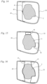
- the Fig. 14 to 16 show different variants of fixing the base body 23 to the robot arm 2.
- a bracket 41 is provided, which is fixed at its ends to the base body 23.
- the bracket 41 can, for example, be screwed to the base body 23 or glued to it.
- the bracket 41 is screwed to the robot arm 2 using one or more fastening screws 42.
- the bracket 41 thus fixes the base body 23 to the robot arm 2.
- clamping profiles 43 are fixed to the base body 23, for example by gluing or screwing.
- the clamping profiles 43 at least partially enclose the robot arm 2 on opposite sides.
- the robot arm 2 is positively fixed to the clamping profiles 43.
- the clamping profiles 43 can be screwed to the robot arm 2, in particular to secure the clamping fixation.
- the embodiment according to Fig. 16 shows a design in which two brackets 41 are arranged on the base body 23 on opposite sides of the robot arm 2.
- the robot arm 2 is held clamped between the two brackets 41.
- An additional Fixing using one or more fastening screws can be advantageous.
- the brackets 41 can be fixed to the base body 23 by gluing or using screws. It can also be provided that the brackets 41 are held elastically on the base body 23 due to their inherent tension. Other types of fastening for fixing the base body 23 to the robot arm 2 can also be advantageous.
- the design of the housing unit 20 is shown in detail.
- the other housing units 17, 18, 19 and 21 are advantageously designed accordingly.
- the sixth housing unit 22 can also be designed accordingly.
- the structure of the housing wall 34 is preferably the same for all housing units of the housing arrangement 4. All of the described fixing variants can also be considered for fixing the base body 23 to the robot arm 2 for all housing units 17 to 22. Other types of fixing can also be advantageous.
Landscapes
- Health & Medical Sciences (AREA)
- Engineering & Computer Science (AREA)
- Life Sciences & Earth Sciences (AREA)
- Biomedical Technology (AREA)
- Animal Behavior & Ethology (AREA)
- General Health & Medical Sciences (AREA)
- Public Health (AREA)
- Veterinary Medicine (AREA)
- Nuclear Medicine, Radiotherapy & Molecular Imaging (AREA)
- Medical Informatics (AREA)
- Pathology (AREA)
- Radiology & Medical Imaging (AREA)
- Surgery (AREA)
- Heart & Thoracic Surgery (AREA)
- Molecular Biology (AREA)
- Physics & Mathematics (AREA)
- Biophysics (AREA)
- High Energy & Nuclear Physics (AREA)
- Optics & Photonics (AREA)
- Robotics (AREA)
- Manipulator (AREA)
- Accommodation For Nursing Or Treatment Tables (AREA)
- Radiation-Therapy Devices (AREA)
- Mechanical Engineering (AREA)
Claims (14)
- Dispositif de positionnement de patient, en particulier pour la thérapie de capture de neutrons par le bore (BNCT), comprenant un bras de robot (2) et un logement de patient (3) maintenu sur le bras de robot (2),
caractérisé en ce que le dispositif de positionnement de patient (1) comprend un agencement de boîtier (4) pour le bras de robot (2), qui comprend au moins une unité (17, 18, 19, 20, 21) formant boîtier qui entoure au moins partiellement le bras de robot (2), l'unité (17, 18, 19, 20, 21) formant boîtier étant fixée sur le bras de robot (2), et en ce que le dispositif de positionnement de patient (1) présente un blindage (33) contre les rayonnements ionisants, au moins une partie du blindage (33) étant agencée sur l'unité (17, 18, 19, 20, 21) formant boîtier. - Dispositif de positionnement de patient selon la revendication 1,
caractérisé en ce que l'unité (17, 18, 19, 20, 21) formant boîtier comprend au moins un couvercle amovible (24) et en ce qu'au moins une partie du blindage (33) est maintenue sur le couvercle (24) et est apte à être retirée avec le couvercle (24). - Dispositif de positionnement de patient selon la revendication 1 ou la revendication 2,
caractérisé en ce que toutes les parties du blindage (33) pour le bras de robot (2) sont fixées à l'agencement de boîtier (4). - Dispositif de positionnement de patient selon l'une des revendications 1 à 3,
caractérisé en ce que le blindage (33) est agencé sur la face interne (39) de l'unité (17, 18, 19, 20, 21) formant boîtier. - Dispositif de positionnement de patient selon l'une des revendications 1 à 4,
caractérisé en ce que le bras de robot (2) présente plusieurs sections mobiles les unes par rapport aux autres et en ce qu'une unité (17, 18, 19, 20, 21) formant boîtier séparée est prévue pour chaque section. - Dispositif de positionnement de patient selon la revendication 5,
caractérisé en ce qu'au moins une unité (17, 18, 19, 20, 21) formant boîtier présente un corps de base (23) fixé sur la section et un couvercle (24) maintenu de manière amovible sur le corps de base (23). - Dispositif de positionnement de patient selon la revendication 6,
caractérisé en ce qu'au moins une unité (17, 18, 19, 20, 21) formant boîtier présente des moyens de positionnement du couvercle (24) par rapport au corps de base (23), notamment un bord périphérique (35). - Dispositif de positionnement de patient selon l'une des revendications 1 à 7,
caractérisé en ce qu'au moins une unité (17, 18, 19, 20, 21) formant boîtier est pourvue au moins partiellement d'une couche d'amortissement (28). - Dispositif de positionnement de patient selon la revendication 8,
caractérisé en ce que la couche d'amortissement (28) est maintenue sur une structure porteuse de l'unité (17, 18, 19, 20, 21) formant boîtier, en particulier sur une coque intérieure (27) de l'unité (17, 18, 19, 20, 21) formant boîtier. - Dispositif de positionnement de patient selon la revendication 8 ou la revendication 9,
caractérisé en ce que la couche d'amortissement (28) est recouverte par une enveloppe extérieure (29). - Dispositif de positionnement de patient selon l'une des revendications 8 à 10,
caractérisé en ce que la couche d'amortissement (28) comprend un matériau d'amortissement élastique. - Dispositif de positionnement de patient selon l'une des revendications 8 à 11,
caractérisé en ce qu'au moins un capteur de contact (31), notamment une pluralité de capteurs de contact (31), est agencé dans la couche d'amortissement (28). - Dispositif de positionnement de patient selon l'une des revendications 1 à 12,
caractérisé en ce que le bras de robot (2) présente au moins cinq, en particulier au moins six axes de mouvement de rotation (11, 12, 13, 14, 15, 16). - Dispositif de positionnement de patient selon la revendication 13,
caractérisé en ce que le bras de robot (2) comprend un châssis de base (5), un carrousel (6) monté sur le châssis de base (5) de manière à pouvoir tourner autour d'un premier axe de mouvement de rotation (11), un bras oscillant (7) monté sur le carrousel (6) de manière à pouvoir tourner autour d'un deuxième axe de mouvement de rotation (12), un bras (8) monté à rotation sur le bras oscillant (7) et une main (9) maintenue sur le bras (8), la main (9) présentant trois axes de mouvement de rotation (14, 15, 16).
Priority Applications (6)
| Application Number | Priority Date | Filing Date | Title |
|---|---|---|---|
| EP20174076.8A EP3909643B1 (fr) | 2020-05-12 | 2020-05-12 | Dispositif de positionnement d'un patient |
| TW109117338A TWI845689B (zh) | 2020-05-12 | 2020-05-25 | 患者定位裝置 |
| US17/231,069 US11951334B2 (en) | 2020-05-12 | 2021-04-15 | Patient positioning device |
| JP2021078449A JP7708507B2 (ja) | 2020-05-12 | 2021-05-06 | 患者位置決め装置 |
| KR1020210060752A KR20210139173A (ko) | 2020-05-12 | 2021-05-11 | 환자 포지셔닝 장치 |
| CN202110515952.7A CN113648548A (zh) | 2020-05-12 | 2021-05-12 | 患者定位装置 |
Applications Claiming Priority (1)
| Application Number | Priority Date | Filing Date | Title |
|---|---|---|---|
| EP20174076.8A EP3909643B1 (fr) | 2020-05-12 | 2020-05-12 | Dispositif de positionnement d'un patient |
Publications (2)
| Publication Number | Publication Date |
|---|---|
| EP3909643A1 EP3909643A1 (fr) | 2021-11-17 |
| EP3909643B1 true EP3909643B1 (fr) | 2024-12-25 |
Family
ID=70681750
Family Applications (1)
| Application Number | Title | Priority Date | Filing Date |
|---|---|---|---|
| EP20174076.8A Active EP3909643B1 (fr) | 2020-05-12 | 2020-05-12 | Dispositif de positionnement d'un patient |
Country Status (6)
| Country | Link |
|---|---|
| US (1) | US11951334B2 (fr) |
| EP (1) | EP3909643B1 (fr) |
| JP (1) | JP7708507B2 (fr) |
| KR (1) | KR20210139173A (fr) |
| CN (1) | CN113648548A (fr) |
| TW (1) | TWI845689B (fr) |
Families Citing this family (2)
| Publication number | Priority date | Publication date | Assignee | Title |
|---|---|---|---|---|
| EP4265216A1 (fr) * | 2022-04-21 | 2023-10-25 | Microsure B.V. | Bras de robot destiné à être utilisé en chirurgie, microchirurgie ou super-microchirurgie |
| TWI880312B (zh) * | 2023-08-24 | 2025-04-11 | 國立清華大學 | 標籤導引影像定位的方法及系統 |
Family Cites Families (13)
| Publication number | Priority date | Publication date | Assignee | Title |
|---|---|---|---|---|
| DE102006020868B3 (de) * | 2006-05-04 | 2007-10-25 | Siemens Ag | Patientenpositioniervorrichtung |
| EP1985237A1 (fr) | 2007-04-23 | 2008-10-29 | Buck Engineering & Consulting GmbH | Dispositif et procédé destinés au positionnement automatique d'un patient |
| WO2013033249A2 (fr) * | 2011-08-29 | 2013-03-07 | Rosa Louis | Dispositif de traitement par irradiation avec des neutrons |
| US9662256B2 (en) * | 2012-07-31 | 2017-05-30 | Varian Medical Systems Uk Limited | Patient positioning and support systems |
| US9757593B2 (en) * | 2012-09-05 | 2017-09-12 | Varian Medical Systems, Inc. | Radiation systems with minimal or no shielding requirement on building |
| JP6789813B2 (ja) * | 2013-10-31 | 2020-11-25 | コーニンクレッカ フィリップス エヌ ヴェKoninklijke Philips N.V. | 物体のx線画像データの提供 |
| EP2883567A1 (fr) * | 2013-12-11 | 2015-06-17 | Buck Engineering & Consulting GmbH | Dispositif de positionnement de patient et procédé de positionnement d'un patient sur un dispositif d'irradiation au moyen d'un dispositif de positionnement de patient |
| CN105920739B (zh) * | 2016-04-14 | 2018-05-08 | 四川大学 | 一种基于六自由度工业机械臂的治疗床控制装置 |
| CN107137826A (zh) * | 2017-04-01 | 2017-09-08 | 四川大学 | 磁共振引导的机器人放射治疗系统 |
| CN107362464A (zh) * | 2017-08-13 | 2017-11-21 | 吴大可 | 精准立体定向放射外科治疗装置 |
| CN107564599B (zh) * | 2017-09-19 | 2024-08-16 | 中国科学院合肥物质科学研究院 | 一种具有伽马射线防护功能的驱动装置及机器人 |
| CN110496321B (zh) * | 2018-05-18 | 2024-04-19 | 中硼(厦门)医疗器械有限公司 | 中子捕获治疗系统及载置台 |
| US11369443B2 (en) * | 2019-06-27 | 2022-06-28 | Cilag Gmbh International | Method of using a surgical modular robotic assembly |
-
2020
- 2020-05-12 EP EP20174076.8A patent/EP3909643B1/fr active Active
- 2020-05-25 TW TW109117338A patent/TWI845689B/zh active
-
2021
- 2021-04-15 US US17/231,069 patent/US11951334B2/en active Active
- 2021-05-06 JP JP2021078449A patent/JP7708507B2/ja active Active
- 2021-05-11 KR KR1020210060752A patent/KR20210139173A/ko active Pending
- 2021-05-12 CN CN202110515952.7A patent/CN113648548A/zh active Pending
Also Published As
| Publication number | Publication date |
|---|---|
| KR20210139173A (ko) | 2021-11-22 |
| CN113648548A (zh) | 2021-11-16 |
| JP7708507B2 (ja) | 2025-07-15 |
| EP3909643A1 (fr) | 2021-11-17 |
| US11951334B2 (en) | 2024-04-09 |
| US20210353486A1 (en) | 2021-11-18 |
| TW202142182A (zh) | 2021-11-16 |
| TWI845689B (zh) | 2024-06-21 |
| JP2021178170A (ja) | 2021-11-18 |
Similar Documents
| Publication | Publication Date | Title |
|---|---|---|
| DE102008055130B4 (de) | Detektoreinheit und damit ausgerüstetes CT - Inspektionssystem | |
| DE102007029192B3 (de) | Gantry mit Ausweichraum für eine Partikeltherapie-Anlage | |
| DE602004011560T2 (de) | Mehrzimmer-strahlungsbehandlungssystem | |
| EP3909643B1 (fr) | Dispositif de positionnement d'un patient | |
| EP1967231B1 (fr) | Dispositif et procédé de vérification de la qualité d'une installation de thérapie à particules | |
| EP2259725B1 (fr) | Dispositif de radiographie et poste de travail medical | |
| EP1967229B1 (fr) | Fantôme et procédé de surveillance de la qualité d'une installation médicale | |
| WO2007025936A1 (fr) | Dispositif de positionnement de patient | |
| EP2825098B1 (fr) | Dispositif détecteur destiné à prendre des images radiographiques d'un objet à représenter | |
| WO2003053520A2 (fr) | Systeme de radiotherapie | |
| JP6072273B2 (ja) | マルチリーフコリメータ、およびそれを用いた放射線治療装置、放射線治療システム | |
| DE102008019345A1 (de) | Röntgenvorrichtung und medizinischer Arbeitsplatz | |
| DE19736192C2 (de) | Bestrahlungsanlage mit mehreren auf ein Zentrum ausgerichteten Strahlenquellen | |
| DE102010034101B4 (de) | Anordnung für die Strahlentherapie mit einem Haltearm zur Unterstützung diagnostischer Bestrahlung | |
| DE102010032131A1 (de) | Linearkinematik mit drehbarem Strahlerkopf | |
| DE102009032430B3 (de) | Strahlentherapieanlage | |
| DE202020005426U1 (de) | Patientenpositioniervorrichtung | |
| EP2883567A1 (fr) | Dispositif de positionnement de patient et procédé de positionnement d'un patient sur un dispositif d'irradiation au moyen d'un dispositif de positionnement de patient | |
| DE102010019017B4 (de) | Bestrahlungsvorrichtung mit einer einzigen vertikalen Führung | |
| EP1479411B2 (fr) | Dispostif d'irradiation de tumeur controlée | |
| EP1477992B1 (fr) | Dispositif de protection contre les radiations avec vitre faisant écran | |
| DE102018207320B4 (de) | Strahlungs-Schutzanordnung | |
| EP2883500A1 (fr) | Dispositif d'irradiation de patient | |
| DE102016210496B4 (de) | Patientenpositioniervorrichtung und medizinischer Arbeitsplatz | |
| DE102016204676A1 (de) | Röntgenbilddetektor und Röntgenbildgebungsgerät mit einer Kollisionserkennungseinheit sowie Verfahren zum Erkennen einer Kollision |
Legal Events
| Date | Code | Title | Description |
|---|---|---|---|
| PUAI | Public reference made under article 153(3) epc to a published international application that has entered the european phase |
Free format text: ORIGINAL CODE: 0009012 |
|
| STAA | Information on the status of an ep patent application or granted ep patent |
Free format text: STATUS: THE APPLICATION HAS BEEN PUBLISHED |
|
| AK | Designated contracting states |
Kind code of ref document: A1 Designated state(s): AL AT BE BG CH CY CZ DE DK EE ES FI FR GB GR HR HU IE IS IT LI LT LU LV MC MK MT NL NO PL PT RO RS SE SI SK SM TR |
|
| B565 | Issuance of search results under rule 164(2) epc |
Effective date: 20201009 |
|
| STAA | Information on the status of an ep patent application or granted ep patent |
Free format text: STATUS: REQUEST FOR EXAMINATION WAS MADE |
|
| 17P | Request for examination filed |
Effective date: 20220516 |
|
| RBV | Designated contracting states (corrected) |
Designated state(s): AL AT BE BG CH CY CZ DE DK EE ES FI FR GB GR HR HU IE IS IT LI LT LU LV MC MK MT NL NO PL PT RO RS SE SI SK SM TR |
|
| GRAP | Despatch of communication of intention to grant a patent |
Free format text: ORIGINAL CODE: EPIDOSNIGR1 |
|
| STAA | Information on the status of an ep patent application or granted ep patent |
Free format text: STATUS: GRANT OF PATENT IS INTENDED |
|
| INTG | Intention to grant announced |
Effective date: 20240724 |
|
| GRAS | Grant fee paid |
Free format text: ORIGINAL CODE: EPIDOSNIGR3 |
|
| GRAA | (expected) grant |
Free format text: ORIGINAL CODE: 0009210 |
|
| STAA | Information on the status of an ep patent application or granted ep patent |
Free format text: STATUS: THE PATENT HAS BEEN GRANTED |
|
| AK | Designated contracting states |
Kind code of ref document: B1 Designated state(s): AL AT BE BG CH CY CZ DE DK EE ES FI FR GB GR HR HU IE IS IT LI LT LU LV MC MK MT NL NO PL PT RO RS SE SI SK SM TR |
|
| REG | Reference to a national code |
Ref country code: GB Ref legal event code: FG4D Free format text: NOT ENGLISH |
|
| REG | Reference to a national code |
Ref country code: CH Ref legal event code: EP |
|
| REG | Reference to a national code |
Ref country code: DE Ref legal event code: R096 Ref document number: 502020010035 Country of ref document: DE |
|
| REG | Reference to a national code |
Ref country code: IE Ref legal event code: FG4D Free format text: LANGUAGE OF EP DOCUMENT: GERMAN |
|
| REG | Reference to a national code |
Ref country code: LT Ref legal event code: MG9D |
|
| PG25 | Lapsed in a contracting state [announced via postgrant information from national office to epo] |
Ref country code: HR Free format text: LAPSE BECAUSE OF FAILURE TO SUBMIT A TRANSLATION OF THE DESCRIPTION OR TO PAY THE FEE WITHIN THE PRESCRIBED TIME-LIMIT Effective date: 20241225 |
|
| PG25 | Lapsed in a contracting state [announced via postgrant information from national office to epo] |
Ref country code: FI Free format text: LAPSE BECAUSE OF FAILURE TO SUBMIT A TRANSLATION OF THE DESCRIPTION OR TO PAY THE FEE WITHIN THE PRESCRIBED TIME-LIMIT Effective date: 20241225 |
|
| PG25 | Lapsed in a contracting state [announced via postgrant information from national office to epo] |
Ref country code: BG Free format text: LAPSE BECAUSE OF FAILURE TO SUBMIT A TRANSLATION OF THE DESCRIPTION OR TO PAY THE FEE WITHIN THE PRESCRIBED TIME-LIMIT Effective date: 20241225 |
|
| PG25 | Lapsed in a contracting state [announced via postgrant information from national office to epo] |
Ref country code: NO Free format text: LAPSE BECAUSE OF FAILURE TO SUBMIT A TRANSLATION OF THE DESCRIPTION OR TO PAY THE FEE WITHIN THE PRESCRIBED TIME-LIMIT Effective date: 20250325 |
|
| PG25 | Lapsed in a contracting state [announced via postgrant information from national office to epo] |
Ref country code: LV Free format text: LAPSE BECAUSE OF FAILURE TO SUBMIT A TRANSLATION OF THE DESCRIPTION OR TO PAY THE FEE WITHIN THE PRESCRIBED TIME-LIMIT Effective date: 20241225 Ref country code: GR Free format text: LAPSE BECAUSE OF FAILURE TO SUBMIT A TRANSLATION OF THE DESCRIPTION OR TO PAY THE FEE WITHIN THE PRESCRIBED TIME-LIMIT Effective date: 20250326 |
|
| PG25 | Lapsed in a contracting state [announced via postgrant information from national office to epo] |
Ref country code: RS Free format text: LAPSE BECAUSE OF FAILURE TO SUBMIT A TRANSLATION OF THE DESCRIPTION OR TO PAY THE FEE WITHIN THE PRESCRIBED TIME-LIMIT Effective date: 20250325 |
|
| REG | Reference to a national code |
Ref country code: NL Ref legal event code: MP Effective date: 20241225 |
|
| PG25 | Lapsed in a contracting state [announced via postgrant information from national office to epo] |
Ref country code: NL Free format text: LAPSE BECAUSE OF FAILURE TO SUBMIT A TRANSLATION OF THE DESCRIPTION OR TO PAY THE FEE WITHIN THE PRESCRIBED TIME-LIMIT Effective date: 20241225 |
|
| PG25 | Lapsed in a contracting state [announced via postgrant information from national office to epo] |
Ref country code: SM Free format text: LAPSE BECAUSE OF FAILURE TO SUBMIT A TRANSLATION OF THE DESCRIPTION OR TO PAY THE FEE WITHIN THE PRESCRIBED TIME-LIMIT Effective date: 20241225 |
|
| PG25 | Lapsed in a contracting state [announced via postgrant information from national office to epo] |
Ref country code: PL Free format text: LAPSE BECAUSE OF FAILURE TO SUBMIT A TRANSLATION OF THE DESCRIPTION OR TO PAY THE FEE WITHIN THE PRESCRIBED TIME-LIMIT Effective date: 20241225 |
|
| PGFP | Annual fee paid to national office [announced via postgrant information from national office to epo] |
Ref country code: DE Payment date: 20250521 Year of fee payment: 6 |
|
| PG25 | Lapsed in a contracting state [announced via postgrant information from national office to epo] |
Ref country code: ES Free format text: LAPSE BECAUSE OF FAILURE TO SUBMIT A TRANSLATION OF THE DESCRIPTION OR TO PAY THE FEE WITHIN THE PRESCRIBED TIME-LIMIT Effective date: 20241225 |
|
| PGFP | Annual fee paid to national office [announced via postgrant information from national office to epo] |
Ref country code: GB Payment date: 20250527 Year of fee payment: 6 |
|
| PG25 | Lapsed in a contracting state [announced via postgrant information from national office to epo] |
Ref country code: IS Free format text: LAPSE BECAUSE OF FAILURE TO SUBMIT A TRANSLATION OF THE DESCRIPTION OR TO PAY THE FEE WITHIN THE PRESCRIBED TIME-LIMIT Effective date: 20250425 |
|
| PG25 | Lapsed in a contracting state [announced via postgrant information from national office to epo] |
Ref country code: PT Free format text: LAPSE BECAUSE OF FAILURE TO SUBMIT A TRANSLATION OF THE DESCRIPTION OR TO PAY THE FEE WITHIN THE PRESCRIBED TIME-LIMIT Effective date: 20250428 |
|
| PG25 | Lapsed in a contracting state [announced via postgrant information from national office to epo] |
Ref country code: EE Free format text: LAPSE BECAUSE OF FAILURE TO SUBMIT A TRANSLATION OF THE DESCRIPTION OR TO PAY THE FEE WITHIN THE PRESCRIBED TIME-LIMIT Effective date: 20241225 |
|
| PG25 | Lapsed in a contracting state [announced via postgrant information from national office to epo] |
Ref country code: RO Free format text: LAPSE BECAUSE OF FAILURE TO SUBMIT A TRANSLATION OF THE DESCRIPTION OR TO PAY THE FEE WITHIN THE PRESCRIBED TIME-LIMIT Effective date: 20241225 |
|
| PG25 | Lapsed in a contracting state [announced via postgrant information from national office to epo] |
Ref country code: SK Free format text: LAPSE BECAUSE OF FAILURE TO SUBMIT A TRANSLATION OF THE DESCRIPTION OR TO PAY THE FEE WITHIN THE PRESCRIBED TIME-LIMIT Effective date: 20241225 |
|
| PG25 | Lapsed in a contracting state [announced via postgrant information from national office to epo] |
Ref country code: CZ Free format text: LAPSE BECAUSE OF FAILURE TO SUBMIT A TRANSLATION OF THE DESCRIPTION OR TO PAY THE FEE WITHIN THE PRESCRIBED TIME-LIMIT Effective date: 20241225 |
|
| PG25 | Lapsed in a contracting state [announced via postgrant information from national office to epo] |
Ref country code: IT Free format text: LAPSE BECAUSE OF FAILURE TO SUBMIT A TRANSLATION OF THE DESCRIPTION OR TO PAY THE FEE WITHIN THE PRESCRIBED TIME-LIMIT Effective date: 20241225 |
|
| PG25 | Lapsed in a contracting state [announced via postgrant information from national office to epo] |
Ref country code: SE Free format text: LAPSE BECAUSE OF FAILURE TO SUBMIT A TRANSLATION OF THE DESCRIPTION OR TO PAY THE FEE WITHIN THE PRESCRIBED TIME-LIMIT Effective date: 20241225 |
|
| REG | Reference to a national code |
Ref country code: DE Ref legal event code: R097 Ref document number: 502020010035 Country of ref document: DE |
|
| PG25 | Lapsed in a contracting state [announced via postgrant information from national office to epo] |
Ref country code: DK Free format text: LAPSE BECAUSE OF FAILURE TO SUBMIT A TRANSLATION OF THE DESCRIPTION OR TO PAY THE FEE WITHIN THE PRESCRIBED TIME-LIMIT Effective date: 20241225 |
|
| PLBE | No opposition filed within time limit |
Free format text: ORIGINAL CODE: 0009261 |
|
| STAA | Information on the status of an ep patent application or granted ep patent |
Free format text: STATUS: NO OPPOSITION FILED WITHIN TIME LIMIT |
|
| REG | Reference to a national code |
Ref country code: CH Ref legal event code: L10 Free format text: ST27 STATUS EVENT CODE: U-0-0-L10-L00 (AS PROVIDED BY THE NATIONAL OFFICE) Effective date: 20251105 |
|
| 26N | No opposition filed |
Effective date: 20250926 |
|
| REG | Reference to a national code |
Ref country code: CH Ref legal event code: H13 Free format text: ST27 STATUS EVENT CODE: U-0-0-H10-H13 (AS PROVIDED BY THE NATIONAL OFFICE) Effective date: 20251223 |
|
| PG25 | Lapsed in a contracting state [announced via postgrant information from national office to epo] |
Ref country code: LU Free format text: LAPSE BECAUSE OF NON-PAYMENT OF DUE FEES Effective date: 20250512 |
|
| PG25 | Lapsed in a contracting state [announced via postgrant information from national office to epo] |
Ref country code: CH Free format text: LAPSE BECAUSE OF NON-PAYMENT OF DUE FEES Effective date: 20250531 |
|
| REG | Reference to a national code |
Ref country code: BE Ref legal event code: MM Effective date: 20250531 |
|
| PG25 | Lapsed in a contracting state [announced via postgrant information from national office to epo] |
Ref country code: MC Free format text: LAPSE BECAUSE OF FAILURE TO SUBMIT A TRANSLATION OF THE DESCRIPTION OR TO PAY THE FEE WITHIN THE PRESCRIBED TIME-LIMIT Effective date: 20241225 |
|
| PG25 | Lapsed in a contracting state [announced via postgrant information from national office to epo] |
Ref country code: IE Free format text: LAPSE BECAUSE OF NON-PAYMENT OF DUE FEES Effective date: 20250512 |
|
| PG25 | Lapsed in a contracting state [announced via postgrant information from national office to epo] |
Ref country code: BE Free format text: LAPSE BECAUSE OF NON-PAYMENT OF DUE FEES Effective date: 20250531 |
|
| PG25 | Lapsed in a contracting state [announced via postgrant information from national office to epo] |
Ref country code: FR Free format text: LAPSE BECAUSE OF NON-PAYMENT OF DUE FEES Effective date: 20250531 |