EP3909650A1 - Véhicule équipé d'un système de lutte contre l'incendie - Google Patents
Véhicule équipé d'un système de lutte contre l'incendie Download PDFInfo
- Publication number
- EP3909650A1 EP3909650A1 EP21173919.8A EP21173919A EP3909650A1 EP 3909650 A1 EP3909650 A1 EP 3909650A1 EP 21173919 A EP21173919 A EP 21173919A EP 3909650 A1 EP3909650 A1 EP 3909650A1
- Authority
- EP
- European Patent Office
- Prior art keywords
- vehicle
- energy storage
- vehicle according
- storage means
- diffuser
- Prior art date
- Legal status (The legal status is an assumption and is not a legal conclusion. Google has not performed a legal analysis and makes no representation as to the accuracy of the status listed.)
- Granted
Links
Images


Classifications
-
- A—HUMAN NECESSITIES
- A62—LIFE-SAVING; FIRE-FIGHTING
- A62C—FIRE-FIGHTING
- A62C3/00—Fire prevention, containment or extinguishing specially adapted for particular objects or places
- A62C3/07—Fire prevention, containment or extinguishing specially adapted for particular objects or places in vehicles, e.g. in road vehicles
-
- A—HUMAN NECESSITIES
- A62—LIFE-SAVING; FIRE-FIGHTING
- A62C—FIRE-FIGHTING
- A62C3/00—Fire prevention, containment or extinguishing specially adapted for particular objects or places
- A62C3/06—Fire prevention, containment or extinguishing specially adapted for particular objects or places of highly inflammable material, e.g. light metals, petroleum products
- A62C3/065—Fire prevention, containment or extinguishing specially adapted for particular objects or places of highly inflammable material, e.g. light metals, petroleum products for containers filled with inflammable liquids
-
- A—HUMAN NECESSITIES
- A62—LIFE-SAVING; FIRE-FIGHTING
- A62C—FIRE-FIGHTING
- A62C3/00—Fire prevention, containment or extinguishing specially adapted for particular objects or places
- A62C3/16—Fire prevention, containment or extinguishing specially adapted for particular objects or places in electrical installations, e.g. cableways
-
- A—HUMAN NECESSITIES
- A62—LIFE-SAVING; FIRE-FIGHTING
- A62C—FIRE-FIGHTING
- A62C31/00—Delivery of fire-extinguishing material
-
- A—HUMAN NECESSITIES
- A62—LIFE-SAVING; FIRE-FIGHTING
- A62C—FIRE-FIGHTING
- A62C31/00—Delivery of fire-extinguishing material
- A62C31/02—Nozzles specially adapted for fire-extinguishing
-
- A—HUMAN NECESSITIES
- A62—LIFE-SAVING; FIRE-FIGHTING
- A62C—FIRE-FIGHTING
- A62C31/00—Delivery of fire-extinguishing material
- A62C31/02—Nozzles specially adapted for fire-extinguishing
- A62C31/03—Nozzles specially adapted for fire-extinguishing adjustable, e.g. from spray to jet or vice versa
Definitions
- the present invention relates to a fire extinguishing system for a vehicle, in particular an emergency cooling system for an alternative drive vehicle, such as an electric vehicle or a gas/hydrogen powered vehicle.
- electric vehicles comprise battery packs configured to provide a sufficient source of electrical energy to allow traction of the vehicle as well as the operation of other auxiliary comfort devices such as the air conditioning system or functional devices, such as screens for displaying information useful to passengers.
- the electric batteries used in said vehicles are electrochemical storage devices which, during use in charging and discharging, tend to heat up.
- thermo runaway a phenomenon in which the temperature triggers exothermic reactions that further raise the temperature and therefore consequently leading to disastrous consequences such as explosions or fires that can involve the entire vehicle and its occupants.
- the fuel is normally housed in pressurized tanks carried by the vehicle itself and made of steel or composite material to allow the same to be sealed at high pressure, for example at a pressure greater than 100 bar.
- said battery packs/pressurized tanks are normally housed on the roof of the vehicle in order not to limit the space suitable for passenger transport.
- the object of the present invention is to satisfy the above requirements in an optimized and inexpensive way.
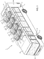
- Figure 1 illustrates a vehicle 1, such as a vehicle for the public transport of people, provided with a plurality of walls 2 defining an internal volume suitable for the transport of passengers.
- said walls comprise a floor, not shown, a plurality of side walls 2a, a front/rear wall 2b and a roof 2c.
- the vehicle 1 comprises a plurality of energy storage means 4 carried by the vehicle 1 itself and configured to define an energy source usable by driving means (not illustrated) of the vehicle 1 allowing the operation thereof.
- Said energy storage means 4 can be packs of electric batteries or compressed gas tanks such as hydrogen or liquid natural gas, LNG (Liquid Natural Gas) or compressed natural gas, CNG (Compressed Natural Gas).
- the vehicle 1 is an electric bus and the energy storage means 4 comprise battery packs 5, however, as is clear from the following, the present invention can be validly used if the energy storage means 4 were pressurized tanks and the vehicle was of a different type.
- the battery packs 5 are housed inside respective casing 6 fixed on the roof 2c of the vehicle 1.
- each casing 6 can be enclosed within a space 7 delimited by a lid 8 enclosing the various casings 6 so as to separate them from the external environment.
- each casing 6 can house inside the same, as is known, in addition to the battery packs 5, relative cables and electronic elements necessary for the transfer of electrical energy between the batteries and the driving means of the vehicle 1, not illustrated.
- the vehicle 1 comprises a fire extinguishing system 10 comprising at least one hydraulic interface 11 configured to couple with a pipe configured to inject a fire extinguishing fluid into the system 10, diffuser means 12 configured to spray towards the energy storage means 4 the fluid injected by means of the hydraulic interface 11 and a hydraulic distribution circuit 13 configured to fluidically connect the hydraulic interface 11 with the diffuser means 12.
- a fire extinguishing system 10 comprising at least one hydraulic interface 11 configured to couple with a pipe configured to inject a fire extinguishing fluid into the system 10, diffuser means 12 configured to spray towards the energy storage means 4 the fluid injected by means of the hydraulic interface 11 and a hydraulic distribution circuit 13 configured to fluidically connect the hydraulic interface 11 with the diffuser means 12.
- the fire extinguishing system 10 comprises a plurality of hydraulic interfaces 11 advantageously obtained in the side walls 2a of the vehicle 1, preferably, as in the case described, in the front and rear portion of the vehicle 1.
- these hydraulic interfaces 11 are made at a height close to the wheels of the vehicle 1, advantageously between the wheels of the vehicle 1 and windows of the vehicle in order to be at human height so as to allow rescuers to easily connect a pipe with the hydraulic interface 11.
- each hydraulic interface 11 comprises an opening configured to allow the insertion of a fire extinguishing type pipe or any pipe suitable for inserting pressurized liquid.
- the fluid inserted can be water or any mixture of water and fire extinguishing agents of a known type.
- the hydraulic distribution circuit 13 advantageously comprises a network of pipes 14, made with a heat and combustion resistant material and configured to fluidically connect the hydraulic interfaces 11 with the diffuser means 12.
- vertical pipes 14 are provided, carried by the side walls 2a and connected directly to a respective hydraulic interface 11 and horizontal pipes 14 carried by the roof 2c connected to the vertical pipes 14 and to each diffuser means 12.
- the diffuser means 12 advantageously comprise at least one nozzle 16, 17, as described in the following and selectively connectable to an end portion of a pipe 14 and facing a respective casing 6 of a battery pack 5.
- FIG. 2 illustrates a first embodiment of the diffuser means 12.
- the diffuser means 12 comprise a nozzle 16 configured to define a direct jet of refrigerant fluid focusing on a limited area of the casing 6 of the battery packs 5.
- the casing 6 advantageously defines an opening 6a provided with a meltable element 15 configured to close the opening 6a when the temperature of the battery pack 5 is lower than a predetermined threshold temperature. If the temperature of the battery pack 5 is higher than the predetermined threshold temperature, said meltable element 15 is configured to melt and leave the opening 6a free so as to allow the latter to communicate with the space 7. In this way, the jet of refrigerant fluid coming from the nozzle 16 can penetrate inside the battery pack 5 by passing through the opening 6a.
- FIG. 3 illustrates a second embodiment of the diffuser means 12.
- the diffuser means 12 comprise a nozzle 17 configured to define a jet of diffused fluid (also called mist or fog) configured to spray a large area of the outer surface of the casing 6.
- Said configuration provides a screen of fluid for thermal protection capable of confining the energy storage means 4 involved from the rest of the vehicle 1.
- the diffuser means 12 can comprise a variable jet nozzle configured to vary the shape of the jet from closed, to full to a fog jet.
- said nozzle is a motorized nozzle that can comprise a lever mechanism, operated by a specialized actuator, configured to vary the opening of the nozzle in order to vary according to the types described above.
- the vehicle 1 comprises temperature sensor means, not illustrated, configured to detect the temperature of each of the energy storage means 4.
- said sensors can be of any type and be placed in the immediate vicinity, for example on the casing 6 or inside the battery packs 5.
- the vehicle 1 comprises, furthermore, an electronic unit electrically connected to the temperature sensor means and comprising processing means configured to process the signal detected by the temperature sensor means and compare it with a threshold temperature stored in the electronic unit.
- said electronic unit can be the ECU of the vehicle 1.
- the driver of the vehicle 1 is warned of the danger of fire due to overheating of the energy storage means 4, by visual or acoustic signalling means such as, for example, a warning light and/or an acoustic signal. In this way, the driver can alert the emergency vehicles and ask for assistance.
- the vehicle 1 can further comprise telecommunication means, not illustrated, electronically connected to the electronic unit and configured to communicate with one or more known emergency stations, for example the fire department, the need for fire rescue and essential vehicle data stored in the electronic unit of the vehicle, such as the position (for example GPS) of the same, the type of vehicle, the licence plate number, the presence of the fire extinguishing system 10 according to the present invention, etc. In this way, if there is an overheating condition of the energy storage means 4, emergency assistance is automatically requested.
- emergency stations for example the fire department
- control of the actuator means can be carried out by the aforementioned electronic unit or remotely by short-range remote control means, for example WiFi.
- Said remote control means can comprise a remote control, provided on the vehicle and usable by the driver or integrated by way of an app that can be downloaded on any smartphone.
- the electronic unit If the electronic unit detects that the temperature of the energy storage means 4 exceeds the predetermined threshold, it will generate an overheating warning signal to the driver of the vehicle 1 and, if foreseen, it will send an intervention request signal to the nearest emergency station.
- the rescuers will be able to connect their pipes directly into the openings of the hydraulic interfaces 11 so as to insert the fluid into the circuit 13. Inside the latter, the fluid will rise to the roof 2c and will be conveyed to each diffuser means 12.
- the jet provided by the nozzle 16 will be direct and therefore will be sent directly to the battery pack 5, flooding the same.
- the electronic unit or remotely the driver of the vehicle 1 or a rescuer can adjust the shape of the jet of the diffuser means 12 according to the type of overheating/fire present in the energy storage means 4.
- the fire extinguishing system 10 it is possible to cool/extinguish a possible ignition of fire relating to the energy storage means 4, thus avoiding an explosion or the spreading of phenomena such as thermal runaway.
- the driver and/or the rescuers can be promptly notified in order to act as soon as possible.
- rescuers are greatly facilitated because they can act at human height to insert the fire extinguishing fluid that will reach the energy storage means 4, even if placed at heights that are difficult to reach or inside panels of the vehicle 1.
- nozzles 16, 17 of different types makes it possible to obtain a versatile fire extinguishing system 10 which can be used on energy storage means 4 provided with closed casings or provided with a fire extinguishing access, such as that by way of the described meltable element.
- heat and flame resistant pipes 14 allows the fire extinguishing fluid to reach, even if it has already spread, various parts of the vehicle 1.
- variable flow nozzle allows to implement an overheating/fire containment strategy optimized according to the specific situation of the energy storage vehicles 4 in total safety.
- the energy storage means 4 can be of various types (electric or explosive fluid) and can be enclosed in casings of different shape and position in the vehicle 1.
- the number of hydraulic interfaces, of energy storage means 4 and the type of the hydraulic circuit 13 can vary as a result of the type of vehicle 1.
- nozzles 16, 17 can be used alternately or in combination with one another.
Landscapes
- Health & Medical Sciences (AREA)
- Public Health (AREA)
- Business, Economics & Management (AREA)
- Emergency Management (AREA)
- Chemical & Material Sciences (AREA)
- Engineering & Computer Science (AREA)
- Chemical Kinetics & Catalysis (AREA)
- General Chemical & Material Sciences (AREA)
- Oil, Petroleum & Natural Gas (AREA)
- Electric Propulsion And Braking For Vehicles (AREA)
- Fire-Extinguishing By Fire Departments, And Fire-Extinguishing Equipment And Control Thereof (AREA)
Applications Claiming Priority (1)
| Application Number | Priority Date | Filing Date | Title |
|---|---|---|---|
| IT102020000011245A IT202000011245A1 (it) | 2020-05-15 | 2020-05-15 | Veicolo provvisto di sistema antincendio |
Publications (3)
| Publication Number | Publication Date |
|---|---|
| EP3909650A1 true EP3909650A1 (fr) | 2021-11-17 |
| EP3909650B1 EP3909650B1 (fr) | 2024-04-17 |
| EP3909650C0 EP3909650C0 (fr) | 2024-04-17 |
Family
ID=71895114
Family Applications (1)
| Application Number | Title | Priority Date | Filing Date |
|---|---|---|---|
| EP21173919.8A Active EP3909650B1 (fr) | 2020-05-15 | 2021-05-14 | Véhicule équipé d'un système de lutte contre l'incendie |
Country Status (2)
| Country | Link |
|---|---|
| EP (1) | EP3909650B1 (fr) |
| IT (1) | IT202000011245A1 (fr) |
Cited By (7)
| Publication number | Priority date | Publication date | Assignee | Title |
|---|---|---|---|---|
| CN114914622A (zh) * | 2022-07-15 | 2022-08-16 | 广东采日能源科技有限公司 | 一种储能集装箱 |
| IT202200003878A1 (it) * | 2022-03-02 | 2023-09-02 | Iveco Spa | Sistema di sicurezza per pacco batterie di propulsione veicolare |
| KR20240096131A (ko) * | 2022-12-19 | 2024-06-26 | 주식회사 한진지티씨 | 지주식 소방호스 관창 |
| KR102809793B1 (ko) * | 2023-12-18 | 2025-05-21 | 한국기계연구원 | 전기차 화재 진압용 이동식 침수조 및 이를 구비한 전기차 화재 진압 장치 |
| EP4663253A1 (fr) * | 2024-06-12 | 2025-12-17 | Iveco S.P.A. | Système d'ancrage pour accrocher une lance à un vehicule, en particulier un véhicule éléctrique |
| EP4674487A1 (fr) * | 2024-07-03 | 2026-01-07 | Tanktech Co., Ltd. | Dispositif pour éteindre des incendies de bus électrique |
| EP4706784A1 (fr) * | 2024-09-06 | 2026-03-11 | Tanktech Co., Ltd. | Appareil d'extinction d'incendie de bus électrique pouvant être chargé et déchargé par un vérin hydraulique |
Citations (5)
| Publication number | Priority date | Publication date | Assignee | Title |
|---|---|---|---|---|
| DE102012208000A1 (de) * | 2012-05-14 | 2013-11-14 | Robert Bosch Gmbh | Verfahren und Vorrichtung zum Erkennen eines Brandes oder eines unmittelbar bevorstehenden Brandes eines Kraftfahrzeugs |
| FR2991258A1 (fr) * | 2012-05-30 | 2013-12-06 | Peugeot Citroen Automobiles Sa | Systeme de batteries de vehicule comportant un conduit d'eau comprenant un systeme d'obstruction |
| US20160346573A1 (en) * | 2015-06-01 | 2016-12-01 | Bradley Dean Carson | Lithium battery fire suppression water hose system |
| US20180289996A1 (en) * | 2017-04-07 | 2018-10-11 | Hyundai Motor Company | System and controlling method for extinguishing fire in battery of vehicle |
| CN111017024A (zh) * | 2019-12-26 | 2020-04-17 | 天津广通汽车有限公司 | 电动客车 |
-
2020
- 2020-05-15 IT IT102020000011245A patent/IT202000011245A1/it unknown
-
2021
- 2021-05-14 EP EP21173919.8A patent/EP3909650B1/fr active Active
Patent Citations (5)
| Publication number | Priority date | Publication date | Assignee | Title |
|---|---|---|---|---|
| DE102012208000A1 (de) * | 2012-05-14 | 2013-11-14 | Robert Bosch Gmbh | Verfahren und Vorrichtung zum Erkennen eines Brandes oder eines unmittelbar bevorstehenden Brandes eines Kraftfahrzeugs |
| FR2991258A1 (fr) * | 2012-05-30 | 2013-12-06 | Peugeot Citroen Automobiles Sa | Systeme de batteries de vehicule comportant un conduit d'eau comprenant un systeme d'obstruction |
| US20160346573A1 (en) * | 2015-06-01 | 2016-12-01 | Bradley Dean Carson | Lithium battery fire suppression water hose system |
| US20180289996A1 (en) * | 2017-04-07 | 2018-10-11 | Hyundai Motor Company | System and controlling method for extinguishing fire in battery of vehicle |
| CN111017024A (zh) * | 2019-12-26 | 2020-04-17 | 天津广通汽车有限公司 | 电动客车 |
Cited By (10)
| Publication number | Priority date | Publication date | Assignee | Title |
|---|---|---|---|---|
| IT202200003878A1 (it) * | 2022-03-02 | 2023-09-02 | Iveco Spa | Sistema di sicurezza per pacco batterie di propulsione veicolare |
| EP4238614A1 (fr) * | 2022-03-02 | 2023-09-06 | Iveco S.p.A. | Système de sécurité pour les blocs de batterie de propulsion d'un véhicule |
| CN114914622A (zh) * | 2022-07-15 | 2022-08-16 | 广东采日能源科技有限公司 | 一种储能集装箱 |
| CN114914622B (zh) * | 2022-07-15 | 2022-09-30 | 广东采日能源科技有限公司 | 一种储能集装箱 |
| KR20240096131A (ko) * | 2022-12-19 | 2024-06-26 | 주식회사 한진지티씨 | 지주식 소방호스 관창 |
| KR102809793B1 (ko) * | 2023-12-18 | 2025-05-21 | 한국기계연구원 | 전기차 화재 진압용 이동식 침수조 및 이를 구비한 전기차 화재 진압 장치 |
| EP4663253A1 (fr) * | 2024-06-12 | 2025-12-17 | Iveco S.P.A. | Système d'ancrage pour accrocher une lance à un vehicule, en particulier un véhicule éléctrique |
| EP4674487A1 (fr) * | 2024-07-03 | 2026-01-07 | Tanktech Co., Ltd. | Dispositif pour éteindre des incendies de bus électrique |
| WO2026010039A1 (fr) * | 2024-07-03 | 2026-01-08 | 탱크테크 주식회사 | Appareil d'extinction d'incendie pour bus électrique |
| EP4706784A1 (fr) * | 2024-09-06 | 2026-03-11 | Tanktech Co., Ltd. | Appareil d'extinction d'incendie de bus électrique pouvant être chargé et déchargé par un vérin hydraulique |
Also Published As
| Publication number | Publication date |
|---|---|
| EP3909650B1 (fr) | 2024-04-17 |
| IT202000011245A1 (it) | 2021-11-15 |
| EP3909650C0 (fr) | 2024-04-17 |
Similar Documents
| Publication | Publication Date | Title |
|---|---|---|
| EP3909650B1 (fr) | Véhicule équipé d'un système de lutte contre l'incendie | |
| US20220161078A1 (en) | Method and cooling arrangement for cooling and dousing an overheated battery module of a high-voltage battery for a motor vehicle | |
| ES2953630T3 (es) | Sistemas para monitorización de componentes de sistemas de combustible volátil | |
| CN109552080B (zh) | 车辆 | |
| US20230181950A1 (en) | Battery arrangement and method for fighting a battery fire and motor vehicle | |
| KR102437707B1 (ko) | 차량용 배터리 화재 진화 시스템 및 제어방법 | |
| US9573005B2 (en) | Protection device | |
| CN112972938A (zh) | 具有用于车辆外部的灭火剂的供给接头的机动车 | |
| KR101610476B1 (ko) | 차량 화재 발생시 수소 탱크 안전성 경보 장치 및 방법 | |
| CN111137173B (zh) | 电动汽车及其热失控防护方法 | |
| CN114604071A (zh) | 具有用于扑灭电池火灾的优化的接近性的机动车 | |
| CN210542972U (zh) | 动力电池消防装置和车辆 | |
| EP3910721A1 (fr) | Bloc de batteries avec système de securité contre un claquage thermique et véhicule avec un tel bloc de batteries | |
| US20190193658A1 (en) | Modular safety kit | |
| CN116071882B (zh) | 一种域控制器处理分布式感知信号的方法及装置 | |
| CN111744124A (zh) | 一种新能源汽车充电自动灭火装置 | |
| CN111821617A (zh) | 一种悬挂式电动汽车火灾保护装置 | |
| CN214860733U (zh) | 一种车载式电池火灾灭火装置 | |
| CN108189743B (zh) | 一种分舱式防爆运油车 | |
| JP2009502376A (ja) | 自動車における安全システム | |
| US12246201B2 (en) | Fire extinguishing apparatus of vehicle | |
| CN212395668U (zh) | 一种汽车车载智能消防器 | |
| KR20250046482A (ko) | 차량의 협동형 화재 진압 시스템용 도킹 장치 및 방법 | |
| KR20220116884A (ko) | 자동차 엔진룸의 자동소화장치 | |
| CN212383107U (zh) | 一种新能源汽车充电自动灭火装置 |
Legal Events
| Date | Code | Title | Description |
|---|---|---|---|
| PUAI | Public reference made under article 153(3) epc to a published international application that has entered the european phase |
Free format text: ORIGINAL CODE: 0009012 |
|
| STAA | Information on the status of an ep patent application or granted ep patent |
Free format text: STATUS: THE APPLICATION HAS BEEN PUBLISHED |
|
| AK | Designated contracting states |
Kind code of ref document: A1 Designated state(s): AL AT BE BG CH CY CZ DE DK EE ES FI FR GB GR HR HU IE IS IT LI LT LU LV MC MK MT NL NO PL PT RO RS SE SI SK SM TR |
|
| B565 | Issuance of search results under rule 164(2) epc |
Effective date: 20211015 |
|
| STAA | Information on the status of an ep patent application or granted ep patent |
Free format text: STATUS: REQUEST FOR EXAMINATION WAS MADE |
|
| 17P | Request for examination filed |
Effective date: 20220509 |
|
| RBV | Designated contracting states (corrected) |
Designated state(s): AL AT BE BG CH CY CZ DE DK EE ES FI FR GB GR HR HU IE IS IT LI LT LU LV MC MK MT NL NO PL PT RO RS SE SI SK SM TR |
|
| GRAP | Despatch of communication of intention to grant a patent |
Free format text: ORIGINAL CODE: EPIDOSNIGR1 |
|
| STAA | Information on the status of an ep patent application or granted ep patent |
Free format text: STATUS: GRANT OF PATENT IS INTENDED |
|
| RIC1 | Information provided on ipc code assigned before grant |
Ipc: A62C 31/03 20060101ALI20231010BHEP Ipc: A62C 31/02 20060101ALI20231010BHEP Ipc: A62C 31/00 20060101ALI20231010BHEP Ipc: A62C 3/16 20060101ALI20231010BHEP Ipc: A62C 3/07 20060101ALI20231010BHEP Ipc: A62C 3/06 20060101AFI20231010BHEP |
|
| INTG | Intention to grant announced |
Effective date: 20231113 |
|
| RIN1 | Information on inventor provided before grant (corrected) |
Inventor name: AIMO BOOT, MARCO |
|
| GRAS | Grant fee paid |
Free format text: ORIGINAL CODE: EPIDOSNIGR3 |
|
| GRAA | (expected) grant |
Free format text: ORIGINAL CODE: 0009210 |
|
| STAA | Information on the status of an ep patent application or granted ep patent |
Free format text: STATUS: THE PATENT HAS BEEN GRANTED |
|
| AK | Designated contracting states |
Kind code of ref document: B1 Designated state(s): AL AT BE BG CH CY CZ DE DK EE ES FI FR GB GR HR HU IE IS IT LI LT LU LV MC MK MT NL NO PL PT RO RS SE SI SK SM TR |
|
| REG | Reference to a national code |
Ref country code: GB Ref legal event code: FG4D |
|
| REG | Reference to a national code |
Ref country code: CH Ref legal event code: EP |
|
| REG | Reference to a national code |
Ref country code: DE Ref legal event code: R096 Ref document number: 602021011798 Country of ref document: DE |
|
| REG | Reference to a national code |
Ref country code: IE Ref legal event code: FG4D |
|
| U01 | Request for unitary effect filed |
Effective date: 20240423 |
|
| U07 | Unitary effect registered |
Designated state(s): AT BE BG DE DK EE FI FR IT LT LU LV MT NL PT SE SI Effective date: 20240429 |
|
| U20 | Renewal fee for the european patent with unitary effect paid |
Year of fee payment: 4 Effective date: 20240514 |
|
| PG25 | Lapsed in a contracting state [announced via postgrant information from national office to epo] |
Ref country code: IS Free format text: LAPSE BECAUSE OF FAILURE TO SUBMIT A TRANSLATION OF THE DESCRIPTION OR TO PAY THE FEE WITHIN THE PRESCRIBED TIME-LIMIT Effective date: 20240817 |
|
| PG25 | Lapsed in a contracting state [announced via postgrant information from national office to epo] |
Ref country code: HR Free format text: LAPSE BECAUSE OF FAILURE TO SUBMIT A TRANSLATION OF THE DESCRIPTION OR TO PAY THE FEE WITHIN THE PRESCRIBED TIME-LIMIT Effective date: 20240417 |
|
| PG25 | Lapsed in a contracting state [announced via postgrant information from national office to epo] |
Ref country code: GR Free format text: LAPSE BECAUSE OF FAILURE TO SUBMIT A TRANSLATION OF THE DESCRIPTION OR TO PAY THE FEE WITHIN THE PRESCRIBED TIME-LIMIT Effective date: 20240718 |
|
| PG25 | Lapsed in a contracting state [announced via postgrant information from national office to epo] |
Ref country code: ES Free format text: LAPSE BECAUSE OF FAILURE TO SUBMIT A TRANSLATION OF THE DESCRIPTION OR TO PAY THE FEE WITHIN THE PRESCRIBED TIME-LIMIT Effective date: 20240417 |
|
| PG25 | Lapsed in a contracting state [announced via postgrant information from national office to epo] |
Ref country code: PL Free format text: LAPSE BECAUSE OF FAILURE TO SUBMIT A TRANSLATION OF THE DESCRIPTION OR TO PAY THE FEE WITHIN THE PRESCRIBED TIME-LIMIT Effective date: 20240417 |
|
| PG25 | Lapsed in a contracting state [announced via postgrant information from national office to epo] |
Ref country code: PL Free format text: LAPSE BECAUSE OF FAILURE TO SUBMIT A TRANSLATION OF THE DESCRIPTION OR TO PAY THE FEE WITHIN THE PRESCRIBED TIME-LIMIT Effective date: 20240417 Ref country code: NO Free format text: LAPSE BECAUSE OF FAILURE TO SUBMIT A TRANSLATION OF THE DESCRIPTION OR TO PAY THE FEE WITHIN THE PRESCRIBED TIME-LIMIT Effective date: 20240717 Ref country code: IS Free format text: LAPSE BECAUSE OF FAILURE TO SUBMIT A TRANSLATION OF THE DESCRIPTION OR TO PAY THE FEE WITHIN THE PRESCRIBED TIME-LIMIT Effective date: 20240817 Ref country code: HR Free format text: LAPSE BECAUSE OF FAILURE TO SUBMIT A TRANSLATION OF THE DESCRIPTION OR TO PAY THE FEE WITHIN THE PRESCRIBED TIME-LIMIT Effective date: 20240417 Ref country code: GR Free format text: LAPSE BECAUSE OF FAILURE TO SUBMIT A TRANSLATION OF THE DESCRIPTION OR TO PAY THE FEE WITHIN THE PRESCRIBED TIME-LIMIT Effective date: 20240718 Ref country code: ES Free format text: LAPSE BECAUSE OF FAILURE TO SUBMIT A TRANSLATION OF THE DESCRIPTION OR TO PAY THE FEE WITHIN THE PRESCRIBED TIME-LIMIT Effective date: 20240417 Ref country code: RS Free format text: LAPSE BECAUSE OF FAILURE TO SUBMIT A TRANSLATION OF THE DESCRIPTION OR TO PAY THE FEE WITHIN THE PRESCRIBED TIME-LIMIT Effective date: 20240717 |
|
| REG | Reference to a national code |
Ref country code: CH Ref legal event code: PL |
|
| REG | Reference to a national code |
Ref country code: DE Ref legal event code: R097 Ref document number: 602021011798 Country of ref document: DE |
|
| PG25 | Lapsed in a contracting state [announced via postgrant information from national office to epo] |
Ref country code: CZ Free format text: LAPSE BECAUSE OF FAILURE TO SUBMIT A TRANSLATION OF THE DESCRIPTION OR TO PAY THE FEE WITHIN THE PRESCRIBED TIME-LIMIT Effective date: 20240417 |
|
| PG25 | Lapsed in a contracting state [announced via postgrant information from national office to epo] |
Ref country code: SK Free format text: LAPSE BECAUSE OF FAILURE TO SUBMIT A TRANSLATION OF THE DESCRIPTION OR TO PAY THE FEE WITHIN THE PRESCRIBED TIME-LIMIT Effective date: 20240417 Ref country code: RO Free format text: LAPSE BECAUSE OF FAILURE TO SUBMIT A TRANSLATION OF THE DESCRIPTION OR TO PAY THE FEE WITHIN THE PRESCRIBED TIME-LIMIT Effective date: 20240417 |
|
| PG25 | Lapsed in a contracting state [announced via postgrant information from national office to epo] |
Ref country code: SM Free format text: LAPSE BECAUSE OF FAILURE TO SUBMIT A TRANSLATION OF THE DESCRIPTION OR TO PAY THE FEE WITHIN THE PRESCRIBED TIME-LIMIT Effective date: 20240417 |
|
| PG25 | Lapsed in a contracting state [announced via postgrant information from national office to epo] |
Ref country code: SM Free format text: LAPSE BECAUSE OF FAILURE TO SUBMIT A TRANSLATION OF THE DESCRIPTION OR TO PAY THE FEE WITHIN THE PRESCRIBED TIME-LIMIT Effective date: 20240417 Ref country code: SK Free format text: LAPSE BECAUSE OF FAILURE TO SUBMIT A TRANSLATION OF THE DESCRIPTION OR TO PAY THE FEE WITHIN THE PRESCRIBED TIME-LIMIT Effective date: 20240417 Ref country code: RO Free format text: LAPSE BECAUSE OF FAILURE TO SUBMIT A TRANSLATION OF THE DESCRIPTION OR TO PAY THE FEE WITHIN THE PRESCRIBED TIME-LIMIT Effective date: 20240417 Ref country code: CZ Free format text: LAPSE BECAUSE OF FAILURE TO SUBMIT A TRANSLATION OF THE DESCRIPTION OR TO PAY THE FEE WITHIN THE PRESCRIBED TIME-LIMIT Effective date: 20240417 Ref country code: MC Free format text: LAPSE BECAUSE OF FAILURE TO SUBMIT A TRANSLATION OF THE DESCRIPTION OR TO PAY THE FEE WITHIN THE PRESCRIBED TIME-LIMIT Effective date: 20240417 Ref country code: CH Free format text: LAPSE BECAUSE OF NON-PAYMENT OF DUE FEES Effective date: 20240531 |
|
| PLBE | No opposition filed within time limit |
Free format text: ORIGINAL CODE: 0009261 |
|
| STAA | Information on the status of an ep patent application or granted ep patent |
Free format text: STATUS: NO OPPOSITION FILED WITHIN TIME LIMIT |
|
| 26N | No opposition filed |
Effective date: 20250120 |
|
| PG25 | Lapsed in a contracting state [announced via postgrant information from national office to epo] |
Ref country code: IE Free format text: LAPSE BECAUSE OF NON-PAYMENT OF DUE FEES Effective date: 20240514 |
|
| U20 | Renewal fee for the european patent with unitary effect paid |
Year of fee payment: 5 Effective date: 20250508 |
|
| PG25 | Lapsed in a contracting state [announced via postgrant information from national office to epo] |
Ref country code: CY Free format text: LAPSE BECAUSE OF FAILURE TO SUBMIT A TRANSLATION OF THE DESCRIPTION OR TO PAY THE FEE WITHIN THE PRESCRIBED TIME-LIMIT; INVALID AB INITIO Effective date: 20210514 |
|
| PG25 | Lapsed in a contracting state [announced via postgrant information from national office to epo] |
Ref country code: HU Free format text: LAPSE BECAUSE OF FAILURE TO SUBMIT A TRANSLATION OF THE DESCRIPTION OR TO PAY THE FEE WITHIN THE PRESCRIBED TIME-LIMIT; INVALID AB INITIO Effective date: 20210514 |
|
| GBPC | Gb: european patent ceased through non-payment of renewal fee |
Effective date: 20250514 |
|
| PG25 | Lapsed in a contracting state [announced via postgrant information from national office to epo] |
Ref country code: GB Free format text: LAPSE BECAUSE OF NON-PAYMENT OF DUE FEES Effective date: 20250514 |
|
| U20 | Renewal fee for the european patent with unitary effect paid |
Year of fee payment: 6 Effective date: 20260409 |