EP3909653B1 - Dispositif de stockage sécurisé des matières inflammables - Google Patents
Dispositif de stockage sécurisé des matières inflammables Download PDFInfo
- Publication number
- EP3909653B1 EP3909653B1 EP21173807.5A EP21173807A EP3909653B1 EP 3909653 B1 EP3909653 B1 EP 3909653B1 EP 21173807 A EP21173807 A EP 21173807A EP 3909653 B1 EP3909653 B1 EP 3909653B1
- Authority
- EP
- European Patent Office
- Prior art keywords
- opening
- container
- lower container
- upper container
- top side
- Prior art date
- Legal status (The legal status is an assumption and is not a legal conclusion. Google has not performed a legal analysis and makes no representation as to the accuracy of the status listed.)
- Active
Links
Images


Classifications
-
- A—HUMAN NECESSITIES
- A62—LIFE-SAVING; FIRE-FIGHTING
- A62C—FIRE-FIGHTING
- A62C3/00—Fire prevention, containment or extinguishing specially adapted for particular objects or places
- A62C3/16—Fire prevention, containment or extinguishing specially adapted for particular objects or places in electrical installations, e.g. cableways
-
- A—HUMAN NECESSITIES
- A62—LIFE-SAVING; FIRE-FIGHTING
- A62C—FIRE-FIGHTING
- A62C35/00—Permanently-installed equipment
- A62C35/02—Permanently-installed equipment with containers for delivering the extinguishing substance
- A62C35/10—Containers destroyed or opened by flames or heat
-
- Y—GENERAL TAGGING OF NEW TECHNOLOGICAL DEVELOPMENTS; GENERAL TAGGING OF CROSS-SECTIONAL TECHNOLOGIES SPANNING OVER SEVERAL SECTIONS OF THE IPC; TECHNICAL SUBJECTS COVERED BY FORMER USPC CROSS-REFERENCE ART COLLECTIONS [XRACs] AND DIGESTS
- Y02—TECHNOLOGIES OR APPLICATIONS FOR MITIGATION OR ADAPTATION AGAINST CLIMATE CHANGE
- Y02E—REDUCTION OF GREENHOUSE GAS [GHG] EMISSIONS, RELATED TO ENERGY GENERATION, TRANSMISSION OR DISTRIBUTION
- Y02E60/00—Enabling technologies; Technologies with a potential or indirect contribution to GHG emissions mitigation
- Y02E60/10—Energy storage using batteries
Definitions
- the present invention relates to a device for the safe storage of combustible substances, in particular lithium-ion accumulators.
- a safety container for storing combustible substances, which trigger safety-critical conditions in the event of a fire is used, for example, in WO 2016/016008 disclosed.
- This is an inner container in which lithium-ion batteries can be stored and which is protected by an outer container.
- receptacles containing the accumulators can be arranged at designated locations. This means that the accumulators in the receiving containers can first be placed in the security container during transport and then transported with it.
- the security container shown there shows a Safety container lower part, in which the dangerous goods are stored, and a safety container upper part.
- the upper part is mainly used for cleaning the gases escaping in the event of a fire using a filter.
- Another security container is known from DE 20 2020 000691 U1 .
- the safety containers known in the prior art therefore prevent the fire from spreading to the surroundings on the one hand and the environment being adversely affected by the exhaust air on the other.
- the object of the present invention is therefore to provide a device which, on the one hand, allows the safe storage of flammable substances in which a fire triggers fires that are otherwise difficult to extinguish with far-reaching after-effects and, on the other hand, enables simple transport of the flammable substances with additional extinguishing devices that can be quickly attached.
- a device for the safe storage of combustible substances comprising a lower container, which is fireproof and has an opening at the top, an upper container, which preferably contains solid, free-flowing extinguishing agent, and has an opening at the bottom and a triggering device with a safety fuse.
- the upper container can be detachably attached above the lower container and the triggering device creates a detachable connection between the upper container and the lower container in the area of the respective opening.
- This releasable connection closes the opening at the top of the lower container and the opening at the bottom of the upper container. After being triggered by a triggering temperature, the fuse releases the opening on the underside of the upper container and the opening on the upper side of the lower container and establishes a conductive connection.
- the device enables the simple attachment of an additional extinguishing-boosting agent when transporting the stored combustible substances, which is triggered instantaneously in the event of a fire.
- the triggering temperature of the triggering device can be between 70 and 150.degree. C., preferably between 95 and 125.degree.
- both containers can be transported and stored separately from one another.
- the containers can, for example, be lifted individually onto a transport vehicle and reassembled on the vehicle. This allows very easy handling, which nevertheless guarantees the greatest possible protection.
- Flammable materials such as lithium-ion batteries from electric vehicles can be stored or transported in the lower fireproof container.
- the upper container which can be filled with an extinguishing agent, offers the necessary security for storing the accumulators in the lower container.
- the extinguishing agent is preferably a solid, free-flowing extinguishing agent such as hollow glass granules. With the aid of the triggering device, if the combustible substance heats up or catches fire, the extinguishing agent can get instantaneously into the lower container via the opening between the lower and upper container.
- This automatic extinguishing device therefore enables the greatest possible protection when storing combustible materials such as lithium-ion batteries in order to avoid a fire with far-reaching consequences.
- the opening between the upper and lower container can be opened depending on the temperature via the safety fuse.
- the exact design of the safety fuse can be adapted to the desired triggering temperature from which the extinguishing agent is to be introduced into the lower container.
- the triggering device can therefore be adapted to the properties of the combustible substance to be stored.
- the triggering device can comprise a membrane, the membrane covering the opening between the upper and lower containers, preferably at the flange opening of the lower container.
- the membrane preferably dissolves from a triggering temperature of 100 to 120 °C. As long as the flammable substance stored in the lower container does not pose a hazard and does not heat up, the membrane therefore forms a barrier for the extinguishing agent located in the upper container and for the fuse. However, dissolving the membrane can then allow the extinguishing agent to penetrate into the lower container.
- the membrane can consist, for example, of acrylonitrile butadiene rubber (NBR) or ethylene propylene diene rubber (EPDM).
- NBR acrylonitrile butadiene rubber
- EPDM ethylene propylene diene rubber
- a membrane made of NBR preferably has a thickness of 0.5 to 5 mm
- a membrane made of EPDM preferably has a thickness of 0.5 to 1 mm.
- the triggering device also includes a slide construction with a fusible link fuse.
- the slide construction may further comprise a slide with at least one pneumatic cylinder, the slide covering the opening between the upper and lower containers in the prestressed position, the fusible link securing the slide in the prestressed position.
- the fusible link holds up to a triggering temperature of 70 to 147 °C, depending on the melting point of the fusible link.
- the melting point preferably corresponds to a temperature of 72, 98, 120 or 147°C.
- the triggering temperature can be adjusted to the place of use and the nature of the substances to be stored.
- the slider construction is fixed to the upper container, for example, together with a piece of tubing, and if necessary it is detached from the lower container via a flange screw connection.
- the opening of the lower container is closed, for example, by means of a sealing flange with a seal.
- the upper container can be moved together with the slide construction and put back on the lower container when it is used again.
- the trigger membrane is screwed back to the flange screw connection instead of the sealing flange.
- the extinguishing agent stored above the slide can penetrate into the lower container.
- the fusible link can act as a secondary safeguard against uncontrolled tripping.
- the melting point of the fusible link can be adjusted to the properties of the stored combustible substance.
- the at least one pneumatic cylinder allows the slide to be actuated mechanically by melting the fuse. More specifically, the slide is held in a preloaded position by the fusible link and is retracted by the pneumatic cylinders as soon as the fuse melts. This opens the opening between the upper and lower containers.
- This secondary safety element thus allows the extinguishing agent to be retained in the event of accidental damage to the membrane.
- Preference can be the slider Actuate the slide construction mechanically by means of a manual release. In the event of a fault, maximum safety is guaranteed.
- a hole can be provided in the sliding construction in the upper container so that the slider can be secured and an unintentional escape of the extinguishing agent can be prevented.
- the opening at the top through which the extinguishing agent enters the lower container can be closed mechanically by means of a cap or cover.
- the upper container is designed as a funnel construction on the underside, with the funnel construction comprising a downpipe.
- the downpipe connects to the opening on the top of the lower container via the release device.
- the funnel design allows the extinguishing agent to be introduced into the lower container with pinpoint accuracy and the extinguishing agent to be completely emptied from the upper container.
- the triggering device can be easily implemented on the downpipe.
- the diameter of the downcomer is preferably essentially adapted to the diameter of the opening at the top of the lower container.
- the downpipe can be connected to the triggering device using a temperature-resistant or high-temperature-resistant hose, with both ends of the hose being able to be fastened using a hose clamp.
- the trigger is in turn connected to the opening at the top of the lower container.
- the triggering device is connected to the lower container by means of a flange.
- connection of the triggering device to the lower or upper container is therefore a detachable connection which can be connected or disconnected very easily. If the upper and lower containers are transported or stored separately, the triggering device can remain connected to the upper container, for example, in order to prevent the extinguishing agent from escaping.
- the downpipe of the upper container can also be closed with a lid or something similar.
- the upper container can comprise a filling opening and a lid at the top, the filling opening being closable with the lid.
- the extinguishing agent can be easily filled into the upper container via this filling opening and the lid protects it Extinguishing media against external environmental influences. Therefore, the upper container can also be transported without any problems.
- the cover can have an activated carbon filter and at least one outlet opening.
- the outlet opening allows gas to be exchanged.
- the activated carbon filter With the help of the activated carbon filter, the escaping gas is filtered in advance and its toxicity is greatly reduced. Some of the materials and gases released when lithium-ion batteries fail are highly toxic and extremely harmful to health.
- the activated carbon filter enables the reaction products of an endangered lithium-ion battery to be filtered out particularly effectively.
- the lower container is preferably double-walled in order to decouple the core temperature inside from the outside surface during a fire and to keep it as low as possible.
- the lower container can have at least one opening on the side.
- This at least one opening or passage can be used to connect water and/or carbon dioxide extinguishing systems from outside the container.
- sensors or other monitoring elements corresponding to the state of the art can also be attached to these openings.
- At least one pressure relief valve is attached to the upper side of the lower container. This pressure relief valve prevents the container from bursting if overpressure suddenly occurs inside the container. This can prevent the lower tank from exploding in the event of a fire.
- the lower container can comprise a lateral opening and a lockable door, the lateral opening being closable with the lockable door. With the help of the door, the materials to be secured can be easily introduced into the lower container.
- the material of the door preferably corresponds to the material of the lower container in order to guarantee the greatest possible safety of the environment. In the event of a fire, the lateral opening with the lockable door does not reduce safety.
- the lower container preferably has opposing, essentially parallel side walls, with pairs of essentially horizontally aligned guides being attached to these side walls inside the container, each at the same height, with a grating being able to be fixed to each of these pairs.
- the inserted gratings can be fixed with screws. These gratings allow the interior of the lower container to be divided horizontally into different levels. As a result, several layers of combustible materials to be stored can be placed and stored in the lower container.
- the gaps inside the lower container can also be filled with extinguishing agent. For example, extinguishing agent bags filled with hollow glass granules can be introduced into the gaps.
- the gratings can be designed in such a way that slippage of the substances stored on the gratings is greatly reduced. This can be made possible, for example, by openings in the gratings.
- Another embodiment of the present invention provides a water sprinkler in the lower tank.
- the water sprinkler can be triggered in stages from a trigger temperature of 57°C to 182°C using a glass fuse.
- a glass fuse is preferred which is triggered at a temperature of 57, 68, 79, 93, 141 or 182 °C.
- different trigger temperatures can be selected. This means that water-based extinguishing can also be carried out redundantly should the stored combustible substance ignite.
- an additive can be added to the extinguishing water to increase the surface tension of the water or the extinguishing and cooling properties as well as environmental protection.
- water, carbon dioxide and/or a gas generator can also be introduced via the at least one opening on the side of the lower container.
- a preferred embodiment provides feet on the underside of the upper and lower container and stacking corners with preferably an opening on the upper side. If the upper container is connected to the lower container, the entire device thus stands on the feet of the lower container.
- the size of the feet is adapted to the size of the stacking corners, so that when the containers are stacked on top of each other, they are stable connection is realized. In other words, the upper container can be stacked on top of the lower container simply by inserting the feet of the upper container into the stacking corners of the lower container.
- the feet also allow the container to be moved with industrial trucks. Furthermore, the feet can have brackets, which are arranged towards the middle of the container, in order to reduce slipping during displacement with an industrial conveyor and to avoid falling down. The same brackets can also be attached to the feet of the upper tank to allow the same advantages when moving the upper tank.
- the stacking corners attached to the top of the containers allow the containers to be manipulated and transported using a lifting device. As a result, the containers can also be easily lifted onto a transport vehicle.
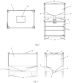
- the device according to the invention for storing combustible substances comprises a lower container 1, an upper container 2 and a triggering device 3 as essential components.
- the lower container 1 is used to store the combustible substances and is therefore designed to be fireproof.
- the lower container 1 has an opening 1' at the top and the upper container 2 has an opening 2' at the bottom.
- the upper container 2 is located above the lower container 1 and contains extinguishing agents with which a fire or an explosion is prevented in the event of the combustible substances stored in the lower container 1 heating up.
- the extinguishing agent can be filled into the same via a filling opening 9 on the top of the upper container.
- the device comprises a triggering device 3.
- This triggering device 3 detachably connects the lower container 1 to the upper container 2.
- the triggering device 3 is preferably located as in Fig. 1a shown in the area of the opening at the top of the lower container 1' and the opening at the bottom of the upper container 2' and closes the two openings. The triggering device 3 therefore prevents the extinguishing agent from being able to get from the upper container 2 into the lower container 1 as long as a certain maximum temperature in the lower container 1 is not exceeded.
- the triggering device 3 particularly preferably comprises a safety fuse.
- a part of the safety fuse melts above a certain temperature and thus triggers the extinguishing process.
- the triggering device 3 releases an opening between the upper and lower containers 2, 1.
- the safety fuse used and its properties can be adapted to the circumstances such as the place of use or the combustible material to be stored. More precisely, essentially the triggering temperature of the fuse can be adjusted.
- the safety fuse preferably melts at a temperature of 70 to 150.degree. C., particularly preferably at a temperature of 95 to 125.degree.
- the front of the lower container 1 can be closed with a door 11 .
- the door 11 allows the flammable substances to be stored to be easily introduced into the lower container 1.
- the door can also be locked to guarantee a firm closure when the device is transported.
- the door 11 can be made of a refractory material or consist of the same material as the lower container 1.
- the triggering device 3 comprises a membrane 4 and a slide construction 5 including fusible link 5 '.
- the membrane can be located at the opening at the top of the lower container 1 and close it.
- the slide structure 5 may be located over the diaphragm 4 as a secondary backup. In the event of accidental damage to the membrane 4, the slide construction 5 thus continues to close the opening 1'.
- Both the membrane 4 and the fusible link 5' melt above a certain temperature. This melting temperature depends on the nature of the membrane 4 or the fusible link 5', which is adapted to the conditions at the place of use.
- the membrane 4 preferably melts at a temperature of 100 to 120.degree.
- the fusible link 5' can also have different triggering temperatures.
- the trigger temperature can be 72, 98, 120 or 147 °C, for example.
- the upper and the lower container 2, 1 particularly preferably include feet 15 or stacking corners 16 on the underside or on the top.
- the feet 15 fit exactly into the stacking corners 16, whereby the upper container 2 can be placed in a simple manner on the lower container 1 and slipping is prevented.
- the feet 15 also allow the containers to be transported or moved using an industrial truck.
- the feet 15 can also have brackets, which can be arranged towards the middle of the container, as in FIGS Figures 1a , 2 (right) and 3 (left) can be seen.
- the stacking corners 16 preferably have openings (see Figures 1 - 4 ) to enable transport using lifting equipment.
- the bottom 3 shows a preferred embodiment of the upper container 2 of the device according to the invention.
- the underside of the upper container 2 is designed as a funnel construction 2".
- the funnel construction 2" ends in a downpipe 8 to which the triggering device 3 can be connected. If the upper container 2 is stacked on top of the lower container 1, the downpipe 8 therefore opens out via the release device 3 into the opening at the top of the lower container 2'.
- the funnel construction 2" enables the extinguishing agent to be poured out completely without leaving residues in the upper container 2.
- the upper container 2 can be selectively connected to the lower container 1 via the downpipe 8 in a material-conducting manner.
- the lid 10 with which the filling opening 9 of the upper container 2 can be closed, can have outlet openings 10'.
- these permit a gas exchange.
- the gases would rise into the upper container 2, since the triggering device 3 releases the opening between the upper and lower containers 2, 1 in the event of a fire. It is therefore important not to make the upper container 2 completely airtight in order to enable gas exchange.
- the cover 10 can include an activated carbon filter, which prevents pollutants from escaping into the environment.
- the downpipe 8 can be connected to the triggering device 3 via a temperature-resistant or high-temperature-resistant hose 17 . Both ends of the hose 17 can each be fastened with a hose clamp. This allows a simple, detachable connection of the upper container 2 to the triggering device 3.
- the triggering device comprises a slide construction 5.
- the triggering device can be releasably connected to the top of the lower container 1 just above the opening 1' using a flange.
- the top of the lower container 1 can also have at least one pressure relief valve 12 . Pressure relief valves 12 prevent the lower container 1 from exploding in the event of a sudden overpressure.
- the 4 the lateral guides 13 and the gratings 14 fixed to the guides 13 are shown.
- a pair of guides 13 are respectively attached to the inside of the side walls of the lower tank at the same level.
- the gratings 14 can be designed in such a way that the substances to be stored are prevented from slipping. This is made possible, for example, by openings in the grating 14 .
- the gratings 14 can be fixed to the guides 13 using screws.
- the cavities in the lower container 1 can be filled with extinguishing agent in order to prevent the stored substances from slipping even more on the one hand and to increase safety on the other hand.
- the extinguishing agent can, for example, be introduced into the lower container 1 by means of extinguishing agent sacks, which preferably comprise hollow glass granules.
- the slide structure 5 comprises two pneumatic cylinders 7 and a slide 6.
- the slide structure 5 is attached to a downpipe which connects to the downpipe 8 of the upper container 2.
- a flange for connection to the lower tank 1 can be provided on the opposite side of the downcomer.
- the fusible link 5' holds the slide in a biased position over the opening at the top of the lower container 1' to which the trigger is attached.
- the slide 6, preferably in addition to the membrane 4 forms a barrier between the openings in the upper and lower containers 2', 1' by closing the downpipe of the triggering device 3.
- the slider construction 5 ( 6 ) together with the piece of hose is on the upper container ( 2 ) is fixed and, if necessary, is detached from the lower container via a flange screw connection.
- the opening at the top of the lower container 1' is closed by means of a sealing flange with a seal.
- the upper container 2 can be brought together with the slider construction 5 and placed on the lower container 1 again when it is used again.
- the trigger membrane 4 is screwed back to the flange screw connection instead of the sealing flange.
- the fusible link 5' can essentially be designed as a connecting link between two hooks, as shown in the figure on the right figure 5 shown.
- a hook is attached to the inside of the drop tube of the release device 3 and a hook is fixed to the underside of the slide 6. After the fusible link 5' has melted, there is no connection between the hooks and the pneumatic cylinders 7, released from their pretension, cause the slide 6 to move.
- the slide 6 can be used as in 6 shown comprise a handle 6'.
- the fusible link 5' breaks and the slide 6 is released from its prestressed position.
- the fusible link 5' Similar to the membrane 4, the fusible link 5' also melts above a certain triggering temperature. This can be selected differently depending on the circumstances by adapting the material and thickness of the fusible link 5'.
Landscapes
- Health & Medical Sciences (AREA)
- Public Health (AREA)
- Business, Economics & Management (AREA)
- Emergency Management (AREA)
- Battery Mounting, Suspending (AREA)
- Filling Or Discharging Of Gas Storage Vessels (AREA)
Claims (14)
- Dispositif de stockage sécurisé de matières inflammables, en particulier d'accumulateurs lithium-ion, comprenant :un récipient inférieur (1) qui est résistant au feu et comprend une ouverture sur le côté supérieur (1'),un récipient supérieur (2) qui comporte un agent d'extinction de préférence solide et apte à l'écoulement et qui comprend une ouverture sur le côté inférieur (2'), etun dispositif de déclenchement (3) comprenant un organe de blocage fusible,le récipient supérieur (2) étant apte à être monté de façon détachable au-dessus du récipient inférieur (1),caractérisé en ce queledit dispositif de déclenchement (3) est destiné à établir une connexion détachable entre le récipient supérieur (2) et le récipient inférieur (1) au niveau de l'ouverture respective (1', 2'),la connexion détachable étant destinée à fermer ladite ouverture sur le côté supérieur du récipient inférieur (1') et ladite ouverture sur le côté inférieur du récipient supérieur (2'), etledit un organe de blocage fusible (3) étant destiné, après le déclenchement par une température de déclenchement, à libérer ladite ouverture sur le côté inférieur du récipient supérieur (2') et ladite ouverture sur le côté supérieur du récipient inférieur (1') et à établir une connexion apte à laisser passer du matériel.
- Dispositif selon la revendication 1, caractérisé en ce que ledit organe de blocage fusible du dispositif de déclenchement (3) est destiné à fondre à une température comprise entre 70 et 150 °C, de préférence entre 95 et 125 °C.
- Dispositif selon l'une quelconque des revendications 1 ou 2, caractérisé en ce que ledit dispositif de déclenchement comprend une membrane (4), ladite membrane (4) couvrant l'ouverture entre les récipients supérieur et inférieur (2, 1), ladite membrane fondant de préférence à partir d'une température de déclenchement comprise entre 100 et 120 °C.
- Dispositif selon l'une quelconque des revendications 1 à 3, caractérisé en ce que ledit dispositif de déclenchement comprend une construction à glissière (5) comprenant un organe de blocage à fusible (5'), ladite construction à glissière (5) comprenant une glissière (6) comportant au moins un vérin pneumatique (7), ladite glissière (6) formant dans une position sollicitée une barrière entre ladite ouverture sur le côté supérieur du récipient inférieur (1') et ladite ouverture sur le côté inférieure du récipient supérieur (2'), ledit organe de blocage à fusible (5') maintenant ladite glissière (6) dans la position sollicitée jusqu'à la température de déclenchement, la température de déclenchement dudit organe de blocage à fusible (5') étant de préférence sélectionnée dans le groupe comportant les températures de 72 °C, 98 °C, 120 °C et 147 °C.
- Dispositif selon l'une quelconque des revendications 1 à 4, caractérisé en ce que le récipient supérieur (2) est réalisé, sur son côté inférieur, sous forme d'une construction à entonnoir (2"), ladite construction à entonnoir (2") comprenant un tuyau de descente (8), ledit dispositif de déclenchement (3) reliant le tuyau de descente (8) à l'ouverture sur le côté supérieur du récipient inférieur (2').
- Dispositif selon l'une quelconque des revendications 1 à 5, caractérisé en ce que le récipient supérieur (2) comprend sur son côté supérieur une ouverture de remplissage (9) et un couvercle (10), ledit couvercle (10) étant apte à fermer ladite ouverture de remplissage (9).
- Dispositif selon la revendication 6, caractérisé en ce que ledit couvercle (10) comprend un filtre à charbon actif et au moins une ouverture de sortie (10').
- Dispositif selon l'une quelconque des revendications 1 à 7, caractérisé en ce que le récipient inférieur (1) est un récipient à double paroi.
- Dispositif selon l'une quelconque des revendications 1 à 8, caractérisé en ce que le récipient inférieur (1) comprend sur son côté latéral au moins une ouverture apte à être fermée.
- Dispositif selon la revendication 9, caractérisé en ce qu'il comprend sur le récipient inférieur (1) une porte verrouillable (11), ladite porte verrouillable (11) étant apte à fermer ladite ouverture latérale.
- Dispositif selon l'une quelconque des revendications 1 à 10, caractérisé en ce au moins une soupape de sécurité (12) est disposée sur le côté supérieur du récipient inférieur (1).
- Dispositif selon l'une quelconque des revendications 1 à 11, caractérisé en ce le récipient inférieur (1) comprend des parois opposées sensiblement parallèles, à l'intérieur du récipient sur ces côtés latérales étant disposés au moins une paire d'organes de guidage (13), qui sont orientés sensiblement en direction horizontale, chacun sur l'une des parois et au même niveau, une grille (14) étant apte à être fixée sur lesdits organes de guidage (13).
- Dispositif selon l'une quelconque des revendications 1 à 12, caractérisé en ce qu'il comprend un sprinkler à eau dans le récipient inférieur (1), ledit sprinkler à eau étant apte à être déclenché à partir d'une température de déclenchement moyennant un fusible en verre, la température de déclenchement dudit fusible en verre étant de préférence sélectionnée dans le groupe comportant les températures de 57 °C, 68 °C, 79 °C, 73 °C, 141 °C et 182 °C.
- Dispositif selon l'une quelconque des revendications 1 à 13, caractérisé en ce les récipients supérieur et inférieur (2, 1) comprennent des pieds (15) sur le côté inférieur et sur le côté supérieur des coins de gerbage (16) qui ont de préférence une percée.
Applications Claiming Priority (1)
| Application Number | Priority Date | Filing Date | Title |
|---|---|---|---|
| AT504342020 | 2020-05-15 |
Publications (3)
| Publication Number | Publication Date |
|---|---|
| EP3909653A1 EP3909653A1 (fr) | 2021-11-17 |
| EP3909653B1 true EP3909653B1 (fr) | 2023-05-10 |
| EP3909653B8 EP3909653B8 (fr) | 2023-06-21 |
Family
ID=75936707
Family Applications (1)
| Application Number | Title | Priority Date | Filing Date |
|---|---|---|---|
| EP21173807.5A Active EP3909653B8 (fr) | 2020-05-15 | 2021-05-14 | Dispositif de stockage sécurisé des matières inflammables |
Country Status (1)
| Country | Link |
|---|---|
| EP (1) | EP3909653B8 (fr) |
Family Cites Families (4)
| Publication number | Priority date | Publication date | Assignee | Title |
|---|---|---|---|---|
| DE102011080706A1 (de) | 2011-08-09 | 2013-02-14 | Li-Tec Battery Gmbh | Verfahren zum Löschen eines Brandes einer in einem Behälter angeordneten elektrochemischen Vorrichtung und Behälter |
| US9415248B2 (en) * | 2012-04-05 | 2016-08-16 | The Boeing Company | Fire extinguishment container |
| DE102014110654A1 (de) | 2014-07-29 | 2016-02-04 | Genius Patentverwertung Gmbh & Co. Kg | Vorrichtung und Verfahren zum Transport von galvanischen Zellen |
| DE202020000691U1 (de) * | 2020-02-19 | 2020-03-12 | Andre Schuhmacher | Vorrichtung zum selbstständigen Löschen von Bränden verursacht durch Batterien |
-
2021
- 2021-05-14 EP EP21173807.5A patent/EP3909653B8/fr active Active
Also Published As
| Publication number | Publication date |
|---|---|
| EP3909653A1 (fr) | 2021-11-17 |
| EP3909653B8 (fr) | 2023-06-21 |
Similar Documents
| Publication | Publication Date | Title |
|---|---|---|
| EP3778430B1 (fr) | Récipient destiné à accueillir des produits dangereux | |
| EP3890843B1 (fr) | Système de protection pour chargement dangereux, en particulier pour un véhicule électrique défectueux ou accidenté, contenant pour un tel véhicule et procédé pour sa protection | |
| DE102020000211B4 (de) | Löschcontainer | |
| WO2016016008A1 (fr) | Dispositif et procédé servant au transport de cellules galvaniques | |
| EP3356630B1 (fr) | Coffret de sécurité | |
| EP2922133B1 (fr) | Dispositif et procédé destinés au transport de cellules galvaniques | |
| EP4274008A1 (fr) | Récipient de stockage des batteries, ainsi que son?utilisation | |
| EP3436164B1 (fr) | Sac extincteur | |
| DE102014209076A1 (de) | Feuerschutz-Rollwagen und Feuerschutzvorrichtung mit einem derartigen Feuerschutz-Rollwagen | |
| DE202021001906U1 (de) | Lagercontainer für Akkus | |
| DE202020101186U1 (de) | Vorrichtung zum Abtransportieren eines beschädigten Elektrofahrzeuges | |
| DE202018101600U1 (de) | Transportbehälter | |
| EP4660009A2 (fr) | Récipient pour l'hévarie | |
| CH716704B1 (de) | Automatisches Kühl-und Feuerlöschsystem. | |
| DE102018129262B4 (de) | Vorrichtung und Brandschutzvorrichtung mit Sicherheitshülle für Fahrzeuge | |
| EP3909653B1 (fr) | Dispositif de stockage sécurisé des matières inflammables | |
| EP2537768A2 (fr) | Dispositif de transport de produits dangereux | |
| DE3905118C2 (de) | Vorrichtung zum Transport von Feuerlöschmitteln und Feuerlöschgeräten | |
| DE2209111A1 (de) | Metallischer behaelter | |
| EP3357104B1 (fr) | Coffre de sécurité | |
| EP4511139B1 (fr) | Dispositif de lutte contre les incendies | |
| WO2006111108A1 (fr) | Contenant permettant de conserver en toute securite un liquide dangereux | |
| DE202025102856U1 (de) | Aufbewahrungsvorrichtung | |
| DE102005018000B3 (de) | Behälter zum sicheren Aufbewahren einer gefährlichen Flüssigkeit | |
| EP4279148A1 (fr) | Système d'extinction pour véhicules, en particulier pour véhicules électriques, et procédé pour son utilisation |
Legal Events
| Date | Code | Title | Description |
|---|---|---|---|
| PUAI | Public reference made under article 153(3) epc to a published international application that has entered the european phase |
Free format text: ORIGINAL CODE: 0009012 |
|
| STAA | Information on the status of an ep patent application or granted ep patent |
Free format text: STATUS: THE APPLICATION HAS BEEN PUBLISHED |
|
| STAA | Information on the status of an ep patent application or granted ep patent |
Free format text: STATUS: REQUEST FOR EXAMINATION WAS MADE |
|
| AK | Designated contracting states |
Kind code of ref document: A1 Designated state(s): AL AT BE BG CH CY CZ DE DK EE ES FI FR GB GR HR HU IE IS IT LI LT LU LV MC MK MT NL NO PL PT RO RS SE SI SK SM TR |
|
| B565 | Issuance of search results under rule 164(2) epc |
Effective date: 20211018 |
|
| 17P | Request for examination filed |
Effective date: 20211025 |
|
| RBV | Designated contracting states (corrected) |
Designated state(s): AL AT BE BG CH CY CZ DE DK EE ES FI FR GB GR HR HU IE IS IT LI LT LU LV MC MK MT NL NO PL PT RO RS SE SI SK SM TR |
|
| RIC1 | Information provided on ipc code assigned before grant |
Ipc: A62C 35/10 20060101ALI20221020BHEP Ipc: A62C 3/16 20060101AFI20221020BHEP |
|
| GRAP | Despatch of communication of intention to grant a patent |
Free format text: ORIGINAL CODE: EPIDOSNIGR1 |
|
| STAA | Information on the status of an ep patent application or granted ep patent |
Free format text: STATUS: GRANT OF PATENT IS INTENDED |
|
| INTG | Intention to grant announced |
Effective date: 20221130 |
|
| GRAS | Grant fee paid |
Free format text: ORIGINAL CODE: EPIDOSNIGR3 |
|
| GRAA | (expected) grant |
Free format text: ORIGINAL CODE: 0009210 |
|
| STAA | Information on the status of an ep patent application or granted ep patent |
Free format text: STATUS: THE PATENT HAS BEEN GRANTED |
|
| REG | Reference to a national code |
Ref country code: DE Ref legal event code: R081 Ref document number: 502021000663 Country of ref document: DE Owner name: HAWE MATTRO GMBH, AT Free format text: FORMER OWNER: MATTRO GMBH, SCHWAZ, AT |
|
| AK | Designated contracting states |
Kind code of ref document: B1 Designated state(s): AL AT BE BG CH CY CZ DE DK EE ES FI FR GB GR HR HU IE IS IT LI LT LU LV MC MK MT NL NO PL PT RO RS SE SI SK SM TR |
|
| REG | Reference to a national code |
Ref country code: GB Ref legal event code: FG4D Free format text: NOT ENGLISH |
|
| REG | Reference to a national code |
Ref country code: AT Ref legal event code: REF Ref document number: 1566132 Country of ref document: AT Kind code of ref document: T Effective date: 20230515 Ref country code: CH Ref legal event code: EP |
|
| REG | Reference to a national code |
Ref country code: DE Ref legal event code: R096 Ref document number: 502021000663 Country of ref document: DE |
|
| RAP4 | Party data changed (patent owner data changed or rights of a patent transferred) |
Owner name: HAWE MATTRO GMBH |
|
| REG | Reference to a national code |
Ref country code: CH Ref legal event code: PK Free format text: BERICHTIGUNG B8 |
|
| REG | Reference to a national code |
Ref country code: IE Ref legal event code: FG4D Free format text: LANGUAGE OF EP DOCUMENT: GERMAN |
|
| P01 | Opt-out of the competence of the unified patent court (upc) registered |
Effective date: 20230523 |
|
| REG | Reference to a national code |
Ref country code: LT Ref legal event code: MG9D |
|
| REG | Reference to a national code |
Ref country code: NL Ref legal event code: MP Effective date: 20230510 |
|
| PG25 | Lapsed in a contracting state [announced via postgrant information from national office to epo] |
Ref country code: SE Free format text: LAPSE BECAUSE OF FAILURE TO SUBMIT A TRANSLATION OF THE DESCRIPTION OR TO PAY THE FEE WITHIN THE PRESCRIBED TIME-LIMIT Effective date: 20230510 Ref country code: PT Free format text: LAPSE BECAUSE OF FAILURE TO SUBMIT A TRANSLATION OF THE DESCRIPTION OR TO PAY THE FEE WITHIN THE PRESCRIBED TIME-LIMIT Effective date: 20230911 Ref country code: NO Free format text: LAPSE BECAUSE OF FAILURE TO SUBMIT A TRANSLATION OF THE DESCRIPTION OR TO PAY THE FEE WITHIN THE PRESCRIBED TIME-LIMIT Effective date: 20230810 Ref country code: NL Free format text: LAPSE BECAUSE OF FAILURE TO SUBMIT A TRANSLATION OF THE DESCRIPTION OR TO PAY THE FEE WITHIN THE PRESCRIBED TIME-LIMIT Effective date: 20230510 Ref country code: ES Free format text: LAPSE BECAUSE OF FAILURE TO SUBMIT A TRANSLATION OF THE DESCRIPTION OR TO PAY THE FEE WITHIN THE PRESCRIBED TIME-LIMIT Effective date: 20230510 |
|
| PG25 | Lapsed in a contracting state [announced via postgrant information from national office to epo] |
Ref country code: RS Free format text: LAPSE BECAUSE OF FAILURE TO SUBMIT A TRANSLATION OF THE DESCRIPTION OR TO PAY THE FEE WITHIN THE PRESCRIBED TIME-LIMIT Effective date: 20230510 Ref country code: PL Free format text: LAPSE BECAUSE OF FAILURE TO SUBMIT A TRANSLATION OF THE DESCRIPTION OR TO PAY THE FEE WITHIN THE PRESCRIBED TIME-LIMIT Effective date: 20230510 Ref country code: LV Free format text: LAPSE BECAUSE OF FAILURE TO SUBMIT A TRANSLATION OF THE DESCRIPTION OR TO PAY THE FEE WITHIN THE PRESCRIBED TIME-LIMIT Effective date: 20230510 Ref country code: LT Free format text: LAPSE BECAUSE OF FAILURE TO SUBMIT A TRANSLATION OF THE DESCRIPTION OR TO PAY THE FEE WITHIN THE PRESCRIBED TIME-LIMIT Effective date: 20230510 Ref country code: IS Free format text: LAPSE BECAUSE OF FAILURE TO SUBMIT A TRANSLATION OF THE DESCRIPTION OR TO PAY THE FEE WITHIN THE PRESCRIBED TIME-LIMIT Effective date: 20230910 Ref country code: HR Free format text: LAPSE BECAUSE OF FAILURE TO SUBMIT A TRANSLATION OF THE DESCRIPTION OR TO PAY THE FEE WITHIN THE PRESCRIBED TIME-LIMIT Effective date: 20230510 Ref country code: GR Free format text: LAPSE BECAUSE OF FAILURE TO SUBMIT A TRANSLATION OF THE DESCRIPTION OR TO PAY THE FEE WITHIN THE PRESCRIBED TIME-LIMIT Effective date: 20230811 |
|
| PG25 | Lapsed in a contracting state [announced via postgrant information from national office to epo] |
Ref country code: FI Free format text: LAPSE BECAUSE OF FAILURE TO SUBMIT A TRANSLATION OF THE DESCRIPTION OR TO PAY THE FEE WITHIN THE PRESCRIBED TIME-LIMIT Effective date: 20230510 |
|
| PG25 | Lapsed in a contracting state [announced via postgrant information from national office to epo] |
Ref country code: SK Free format text: LAPSE BECAUSE OF FAILURE TO SUBMIT A TRANSLATION OF THE DESCRIPTION OR TO PAY THE FEE WITHIN THE PRESCRIBED TIME-LIMIT Effective date: 20230510 |
|
| REG | Reference to a national code |
Ref country code: BE Ref legal event code: MM Effective date: 20230531 |
|
| PG25 | Lapsed in a contracting state [announced via postgrant information from national office to epo] |
Ref country code: SM Free format text: LAPSE BECAUSE OF FAILURE TO SUBMIT A TRANSLATION OF THE DESCRIPTION OR TO PAY THE FEE WITHIN THE PRESCRIBED TIME-LIMIT Effective date: 20230510 Ref country code: SK Free format text: LAPSE BECAUSE OF FAILURE TO SUBMIT A TRANSLATION OF THE DESCRIPTION OR TO PAY THE FEE WITHIN THE PRESCRIBED TIME-LIMIT Effective date: 20230510 Ref country code: RO Free format text: LAPSE BECAUSE OF FAILURE TO SUBMIT A TRANSLATION OF THE DESCRIPTION OR TO PAY THE FEE WITHIN THE PRESCRIBED TIME-LIMIT Effective date: 20230510 Ref country code: LU Free format text: LAPSE BECAUSE OF NON-PAYMENT OF DUE FEES Effective date: 20230514 Ref country code: EE Free format text: LAPSE BECAUSE OF FAILURE TO SUBMIT A TRANSLATION OF THE DESCRIPTION OR TO PAY THE FEE WITHIN THE PRESCRIBED TIME-LIMIT Effective date: 20230510 Ref country code: DK Free format text: LAPSE BECAUSE OF FAILURE TO SUBMIT A TRANSLATION OF THE DESCRIPTION OR TO PAY THE FEE WITHIN THE PRESCRIBED TIME-LIMIT Effective date: 20230510 Ref country code: CZ Free format text: LAPSE BECAUSE OF FAILURE TO SUBMIT A TRANSLATION OF THE DESCRIPTION OR TO PAY THE FEE WITHIN THE PRESCRIBED TIME-LIMIT Effective date: 20230510 |
|
| REG | Reference to a national code |
Ref country code: DE Ref legal event code: R097 Ref document number: 502021000663 Country of ref document: DE |
|
| PG25 | Lapsed in a contracting state [announced via postgrant information from national office to epo] |
Ref country code: MC Free format text: LAPSE BECAUSE OF FAILURE TO SUBMIT A TRANSLATION OF THE DESCRIPTION OR TO PAY THE FEE WITHIN THE PRESCRIBED TIME-LIMIT Effective date: 20230510 |
|
| REG | Reference to a national code |
Ref country code: IE Ref legal event code: MM4A |
|
| PG25 | Lapsed in a contracting state [announced via postgrant information from national office to epo] |
Ref country code: MC Free format text: LAPSE BECAUSE OF FAILURE TO SUBMIT A TRANSLATION OF THE DESCRIPTION OR TO PAY THE FEE WITHIN THE PRESCRIBED TIME-LIMIT Effective date: 20230510 |
|
| PLBE | No opposition filed within time limit |
Free format text: ORIGINAL CODE: 0009261 |
|
| STAA | Information on the status of an ep patent application or granted ep patent |
Free format text: STATUS: NO OPPOSITION FILED WITHIN TIME LIMIT |
|
| PG25 | Lapsed in a contracting state [announced via postgrant information from national office to epo] |
Ref country code: IE Free format text: LAPSE BECAUSE OF NON-PAYMENT OF DUE FEES Effective date: 20230514 |
|
| 26N | No opposition filed |
Effective date: 20240213 |
|
| PG25 | Lapsed in a contracting state [announced via postgrant information from national office to epo] |
Ref country code: IE Free format text: LAPSE BECAUSE OF NON-PAYMENT OF DUE FEES Effective date: 20230514 |
|
| PG25 | Lapsed in a contracting state [announced via postgrant information from national office to epo] |
Ref country code: SI Free format text: LAPSE BECAUSE OF FAILURE TO SUBMIT A TRANSLATION OF THE DESCRIPTION OR TO PAY THE FEE WITHIN THE PRESCRIBED TIME-LIMIT Effective date: 20230510 |
|
| PG25 | Lapsed in a contracting state [announced via postgrant information from national office to epo] |
Ref country code: SI Free format text: LAPSE BECAUSE OF FAILURE TO SUBMIT A TRANSLATION OF THE DESCRIPTION OR TO PAY THE FEE WITHIN THE PRESCRIBED TIME-LIMIT Effective date: 20230510 Ref country code: IT Free format text: LAPSE BECAUSE OF FAILURE TO SUBMIT A TRANSLATION OF THE DESCRIPTION OR TO PAY THE FEE WITHIN THE PRESCRIBED TIME-LIMIT Effective date: 20230510 Ref country code: FR Free format text: LAPSE BECAUSE OF NON-PAYMENT OF DUE FEES Effective date: 20230710 Ref country code: BE Free format text: LAPSE BECAUSE OF NON-PAYMENT OF DUE FEES Effective date: 20230531 |
|
| PG25 | Lapsed in a contracting state [announced via postgrant information from national office to epo] |
Ref country code: BG Free format text: LAPSE BECAUSE OF FAILURE TO SUBMIT A TRANSLATION OF THE DESCRIPTION OR TO PAY THE FEE WITHIN THE PRESCRIBED TIME-LIMIT Effective date: 20230510 |
|
| PG25 | Lapsed in a contracting state [announced via postgrant information from national office to epo] |
Ref country code: BG Free format text: LAPSE BECAUSE OF FAILURE TO SUBMIT A TRANSLATION OF THE DESCRIPTION OR TO PAY THE FEE WITHIN THE PRESCRIBED TIME-LIMIT Effective date: 20230510 |
|
| REG | Reference to a national code |
Ref country code: CH Ref legal event code: PL |
|
| PG25 | Lapsed in a contracting state [announced via postgrant information from national office to epo] |
Ref country code: CH Free format text: LAPSE BECAUSE OF NON-PAYMENT OF DUE FEES Effective date: 20240531 |
|
| PGFP | Annual fee paid to national office [announced via postgrant information from national office to epo] |
Ref country code: DE Payment date: 20250521 Year of fee payment: 5 |
|
| PGFP | Annual fee paid to national office [announced via postgrant information from national office to epo] |
Ref country code: AT Payment date: 20250721 Year of fee payment: 5 |
|
| PG25 | Lapsed in a contracting state [announced via postgrant information from national office to epo] |
Ref country code: CY Free format text: LAPSE BECAUSE OF FAILURE TO SUBMIT A TRANSLATION OF THE DESCRIPTION OR TO PAY THE FEE WITHIN THE PRESCRIBED TIME-LIMIT; INVALID AB INITIO Effective date: 20210514 |
|
| PG25 | Lapsed in a contracting state [announced via postgrant information from national office to epo] |
Ref country code: HU Free format text: LAPSE BECAUSE OF FAILURE TO SUBMIT A TRANSLATION OF THE DESCRIPTION OR TO PAY THE FEE WITHIN THE PRESCRIBED TIME-LIMIT; INVALID AB INITIO Effective date: 20210514 |
|
| PG25 | Lapsed in a contracting state [announced via postgrant information from national office to epo] |
Ref country code: TR Free format text: LAPSE BECAUSE OF FAILURE TO SUBMIT A TRANSLATION OF THE DESCRIPTION OR TO PAY THE FEE WITHIN THE PRESCRIBED TIME-LIMIT Effective date: 20230510 |
|
| GBPC | Gb: european patent ceased through non-payment of renewal fee |
Effective date: 20250514 |
|
| PG25 | Lapsed in a contracting state [announced via postgrant information from national office to epo] |
Ref country code: GB Free format text: LAPSE BECAUSE OF NON-PAYMENT OF DUE FEES Effective date: 20250514 |