EP3909657B1 - Modèle réduit de véhicule destiné au fonctionnement sur terre et dans l'eau - Google Patents
Modèle réduit de véhicule destiné au fonctionnement sur terre et dans l'eau Download PDFInfo
- Publication number
- EP3909657B1 EP3909657B1 EP20174636.9A EP20174636A EP3909657B1 EP 3909657 B1 EP3909657 B1 EP 3909657B1 EP 20174636 A EP20174636 A EP 20174636A EP 3909657 B1 EP3909657 B1 EP 3909657B1
- Authority
- EP
- European Patent Office
- Prior art keywords
- model vehicle
- wheels
- housing
- wheel
- water
- Prior art date
- Legal status (The legal status is an assumption and is not a legal conclusion. Google has not performed a legal analysis and makes no representation as to the accuracy of the status listed.)
- Active
Links
Images


Classifications
-
- A—HUMAN NECESSITIES
- A63—SPORTS; GAMES; AMUSEMENTS
- A63H—TOYS, e.g. TOPS, DOLLS, HOOPS OR BUILDING BLOCKS
- A63H17/00—Toy vehicles, e.g. with self-drive; ; Cranes, winches or the like; Accessories therefor
- A63H17/26—Details; Accessories
- A63H17/262—Chassis; Wheel mountings; Wheels; Axles; Suspensions; Fitting body portions to chassis
-
- A—HUMAN NECESSITIES
- A63—SPORTS; GAMES; AMUSEMENTS
- A63H—TOYS, e.g. TOPS, DOLLS, HOOPS OR BUILDING BLOCKS
- A63H23/00—Toy boats; Floating toys; Other aquatic toy devices
- A63H23/10—Other water toys, floating toys, or like buoyant toys
- A63H23/14—Special drives
Definitions
- model vehicles are known from the prior art, for example from US-A-4,902,260 . These are also known as amphibious vehicles or all-terrain vehicles (ATVs). In the known model vehicles, the vehicle is caused to float either by a housing of the chassis designed in the shape of a ship's hull or by the wheels themselves.
- ATVs all-terrain vehicles
- a propulsion of the known model vehicles is effected either by a separate water drive (e.g. a ship's propeller or a jet drive) or by turning the wheels themselves in the water.
- a separate water drive makes the design and operation of the vehicle complex, complicated and expensive, since a water drive must be provided in addition to the wheel drive and the wheel drive must be switched to the water drive when changing from land to water.
- Driving the model vehicle by turning the wheels usually has poor efficiency.
- the running surfaces of the wheels for such a drive are usually provided with an oversized deep profile, so that the model vehicle cannot realistically imitate a real motor vehicle.
- the object of the present invention is to eliminate the disadvantages mentioned and in particular to provide a simply constructed, small, lightweight, inexpensive model vehicle in which the buoyancy required for swimming is provided by a hollow housing of the chassis is made available and that can also be driven in the water with a good level of efficiency simply by turning the wheels.
- a model vehicle with the features of claim 1 is proposed.
- the model vehicle is propelled in the water solely by the driven wheels and the housing and/or the body forms a wheel well for at least each of the drivable wheels, in which the corresponding wheel is arranged.
- the model vehicle according to the invention is designed as a model car and can also be referred to as an amphibious vehicle.
- the buoyancy required to operate the craft in the water is provided by the hollow body of the chassis. This has the advantage that the model vehicle can be modeled on real motor vehicles in a particularly realistic way.
- the propulsion of the model vehicle in the water occurs solely through the rotation of the driven wheels.
- the omission of a water drive e.g. a ship's propeller or a jet drive
- a separate water drive is not required but could be provided in addition to the wheel drive if required.
- At least the driven wheels of the model vehicle are arranged in wheel housings, which preferably enclose the wheels over a circumference of more than 180°.
- the wheel housings are preferably open in the axial direction, ie towards the sides of the vehicle, so that the wheels arranged in them can be viewed from the outside.
- a rotation of the wheels in the wheel housing causes water to be sucked into the wheel housing between the tread of the wheels and an inner wall of the wheel housing on one side (when the vehicle is driving forwards on the rear side in the direction of travel) of the wheels and with the rotation of the wheels as water flow is accelerated.
- On the other side of the wheels when the vehicle is driving forwards on the front side in the direction of travel), the water is ejected out of the wheel housings.
- the pressure in the wheel housings between the tread of the wheels and the inner wall of the wheel housings is lower than that outside the wheel housings. In other words, there is less pressure at the top of the driven wheels than at their underside. This creates additional buoyancy that lifts the wheels, and therefore the entire motor vehicle, further out of the water.
- the model vehicle has a large ground clearance and particularly good off-road mobility.
- a particularly efficient propulsion of the vehicle can be ensured solely by the driven wheels, since these are not arranged too deep in the water due to the additional buoyancy caused by the water current.
- the wheels protrude from the water by at least half their diameter.
- the vehicle When the model vehicle transitions from land to water, it may be that the vehicle is initially relatively deep in the water, in particular so deep that optimal propulsion is not provided by turning the wheels alone.
- the wheels could initially be more than half their diameter submerged in the water.
- the vehicle due to the rotation of the driven wheels immediately or even when the vehicle enters the water and the resulting flow of water in the wheel housings, the vehicle is additionally lifted within a very short time, so that the wheels protrude further out of the water, in particular with at least half its diameter. This means that the particularly efficient drive of the model vehicle in the water is possible again using the wheels alone.
- a running surface and/or a side wall of at least the drivable wheels be designed so that, with driven wheels, the formation of a water flow in to promote the wheel housing.
- the running surface and/or the side wall of at least the drivable wheels can have profile elements distributed over the circumference of the wheels with a surface extension transverse, preferably perpendicular, to a direction of rotation of the driven wheels.
- profile elements act, for example, as wings or shovels and increase the amount of water conveyed into the wheel housing and thus - since the volume in the wheel housing or between the tread of the wheels and the inner wall of the wheel housing is limited and essentially remains constant - the flow speed of the water flow in the wheel arches. This in turn leads to a particularly low pressure in the wheel housings or to a particularly large pressure difference between the inside of the wheel housings and outside of the wheel housings and finally to a particularly high additional lift.
- the profile elements can improve the propulsion of the watercraft since they act like blades of a paddle wheel drive.
- the hollow housing of the chassis which ensures the buoyancy of the model vehicle when operating in water, preferably contains some, particularly preferably all, of the vehicle's electrical and/or electronic components in order to protect them from moisture and from chemical and/or mechanical influences.
- the at least one electric motor, a control unit, a transmission and/or at least one battery for supplying energy to the at least one electric motor and/or the control unit be accommodated in a moisture-tight manner in the housing of the chassis.
- the gearbox is preferably used to convert a relatively high speed of the electric motor into a lower speed (but higher torque) of a drive shaft for the wheels.
- the transmission can compensate for an angular and/or vertical offset between a motor shaft and the drive shaft.
- the control unit comprises at least one board on which electrical and/or electronic components can be attached and/or electrically contacted.
- the control unit includes a microprocessor on which a computer program can run that is programmed to control and operate the model car and executes the control or operating function when the program is processed on the microprocessor.
- a computer program can run through an operating cycle of the model vehicle after the model vehicle has been switched on, which time-variably involves activation/deactivation of the electric motor, a setting the speed of the electric motor, an adjustment of the steering of the model vehicle and others.
- the battery is preferably designed as a chargeable accumulator.
- a Li-Ion battery, a LiPo battery or a LiFePo4 battery is considered.
- the battery is preferably arranged in a low point of the housing so that the model vehicle has the lowest possible center of gravity.
- the housing of the chassis is open at the top, so that after the body has been removed, the interior of the housing can be freely accessed, for example for maintenance or repair purposes.
- the housing of the chassis has at least one access opening that can be closed in a moisture-tight manner with a cover. It is conceivable that the body or a part of it forms the cover for the housing and that after the body is attached to the housing, the latter is closed in a moisture-tight manner.
- the cover can also be formed as a separate part, in which case the bodywork then has nothing to do with the moisture-tight sealing of the housing.
- the housing has at least one first upper access opening, which allows access to the interior of the housing from above.
- the housing can have at least one second lower access opening, which allows access to the interior of the housing from below.
- Alternative or additional side access openings may also be provided on the side of the housing.
- the interior of the housing can be divided into individual chambers that are preferably closed off from one another, so that the electrical and/or electronic components are arranged in different chambers of the housing.
- the battery in its own chamber in order to protect the other components in the housing, which are arranged in one or more other chambers, from heat, leaking battery acid or the like.
- Each chamber is preferably assigned at least one access opening with or without a cover.
- All openings are preferably sealed with moisture-tight lids.
- a seal can be provided between the cover and the edge of the opening.
- glue the cover to the opening with the glue acting as a seal at the same time.
- the cover is preferably detachably fastened to the housing by means of a snap or latching connection and/or at least one screw. Any other possible ways of attaching the cover to the housing in a detachable or non-detachable manner are conceivable.
- At least one drive shaft which is assigned to at least one driven wheel, is guided in a sealed manner through a receiving opening in the housing.
- a stuffing box for sealing purposes can be arranged in the receiving opening.
- the receiving openings for the drive shaft open into separate chambers inside the housing, which are separated from the other chambers.
- receiving openings can also be provided for the sealed passage of the drive shaft(s). The drive shafts are thus led out of the housing in a multi-stage sealed manner. In this way, water can be effectively prevented from penetrating into the housing or reaching the sensitive electrical and/or electronic components.
- the wheels each include a rim of a first material (eg, hard plastic or metal) and a tire of a different material (eg, soft plastic, foam, rubber) mounted thereon.
- a first material eg, hard plastic or metal
- a tire of a different material eg, soft plastic, foam, rubber
- the wheels in particular the tires, are made from a solid material.
- the wheels have air-filled tires that provide additional buoyancy when the model vehicle is operated in water.
- air-filled tires can provide shock absorption and suspension. In this way, the sensitive electrical and/or electronic components of the model vehicle can be protected from mechanical influences (e.g. shocks, impacts, vibrations).
- At least the driven wheels each have a rim with spokes that extend in the radial direction from a hub of the wheel, through which the axis of rotation of the wheel runs, extend to a rim ring on which a tire of the wheel is fitted, at least some of the spokes having a surface extension in the axial direction and protruding in the axial direction beyond a sidewall of the fitted tire.
- the laterally protruding spokes can act like blades of a paddle wheel drive.
- the hollow housing of the chassis and the wheels of the model vehicle are designed in such a way and their respective shape and dimensions are matched to one another that when the model vehicle is operated in the water the wheels are immersed in the water with a maximum of half their diameter.
- the immersed part of the wheels is bounded by the lower arc of the tread and the secant, which corresponds to the water level, when viewed from the side.
- the openings in the wheel housings between the running surface of the wheels and the inner wall of the wheel housings it is not necessary for the openings in the wheel housings between the running surface of the wheels and the inner wall of the wheel housings to be below the water level, since the driven wheels then also pump water into the wheel housings as a result of their rotation and generate a water flow therein , if the openings in the wheel arches are above the water level.
- At least two of the wheels of the model vehicle be mounted on the chassis so that they can be steered about steering axles, with the steerable wheels being able to steer when the model vehicle is operated both on land and in water of the model vehicle allow.
- the steerable wheels of the model vehicle may or may not be simultaneously driven wheels. It is conceivable to adjust the steerable wheels manually, for example, to a specific steering position, with the wheels then automatically maintaining their steering position, for example due to friction, a snap-in connection, etc. Alternatively, it would also be conceivable to use the steerable To change wheels dynamically while driving the model vehicle with servo-assistance, e.g.
- the steerable wheels can be used to change the direction of travel of the vehicle when operating on land. Additional devices, for example a rudder, could be provided on the model vehicle for changing the direction of travel when operating on water.
- the steerable wheels each have a rim with spokes and a disk-shaped covering cap for the spokes or with a disk instead of spokes, with the covering cap or the disk having a radial surface extension and extending from a hub of the wheel, through which the axis of rotation of the wheel runs, extends to a rim ring on which a tire of the wheel is mounted.
- This has the advantage that the cover caps or disks of the steerable wheels act as rudders when operating on water and additional devices for changing the direction of travel when operating on water can thereby be dispensed with.
- the model vehicle has an on/off switch that is accessible from the outside, preferably from above, and via which the model vehicle can be switched on and/or off. It is conceivable that the housing, at least in some areas, is guided so far in the direction of the outside of the model vehicle that the on/off switch can be arranged in this area of the housing. This has the advantage that the electrical components of the switch are also located in the housing and are protected from moisture, etc. An actuating element for actuating the switch can be guided outwards from the switch through an opening in the body.
- the on/off switch be arranged in the housing of the chassis, with an actuating element associated with the on/off switch, via which a user of the model vehicle has access to the on/off switch, being able to be inserted through an opening in the Body protrudes or can be actuated from the outside through an opening in the body.
- the at least one electric motor is automatically switched on and the drivable wheels are switched on driven.
- the steerable wheels are preferably brought into a desired steering position in advance, which is maintained during operation of the model vehicle.
- the model vehicle then drives continuously, for example driving in a circle, while it is activated by the on/off switch.
- additional switches that can be actuated from the outside can be provided, via which, for example, the speed of the vehicle can be set or an additional function of the vehicle (e.g. a flashing light, a siren or an engine noise) can be activated.
- the speed of the vehicle can be set or an additional function of the vehicle (e.g. a flashing light, a siren or an engine noise) can be activated.
- the model vehicle has a remote control (or RC; radio controlled) module, which is preferably arranged in the housing of the chassis.
- This remote control module allows remote control of the model vehicle via a remote control.
- various functions of the vehicle can be remotely controlled and other functions of the vehicle can be preset, for example via switches.
- the motor of the vehicle and a drive for the driven wheels to be switched on via a switch and for the vehicle's steering to be remote-controlled.
- the drive and steering of the vehicle are preferably remote-controlled.
- additional functions of the vehicle can also be remotely controlled.
- the remote-controlled model vehicle is preferably put into a stand-by mode by switching on the on/off switch.
- the at least one electric motor is only switched on and the drivable wheels are driven by actuating a remote control (eg actuating an accelerator lever or a travel switch on the remote control).
- the vehicle can be steered remotely, for example using proportional servo motors or stepper motors.
- the RC module includes a receiving unit for receiving radio signals from a remote control, which transmits on a corresponding frequency.
- the radio signals received contain commands which, for example, cause propulsion in a specific direction (forward or backward) and/or steering in a specific direction (left, right, straight ahead) and/or activation or deactivation of an additional function of the vehicle.
- the RC module can include a transmission unit for transmitting radio signals to the remote control.
- the radio signals include, in particular, feedback on the operating status of the model vehicle (e.g. speed, direction of travel, activation or deactivation of an additional function, a malfunction or the state of charge of the vehicle's battery).
- the RC module is powered by the vehicle's battery.
- the RC module is preferably connected to a control unit of the vehicle, is controlled by it and/or forwards driving commands via the control unit to the corresponding components of the model vehicle (e.g. an electric motor, proportional servo or stepper motors, switches for activation/deactivation of additional functions).
- a model vehicle according to the invention is denoted by the reference numeral 2 in its entirety.
- the model vehicle 2 is based on a real vehicle in a particularly realistic manner.
- the model vehicle 2 is designed as a BMW X6; of course, the model vehicle 2 can also be based on other real vehicles.
- the model vehicle 2 is designed for operation on land and in the water, even if this is not necessarily the case with the real vehicle.
- the model vehicle 2 can also be referred to as an amphibious vehicle.
- the chassis 4 comprises a hollow housing 38 (cf. figures 5 and 7 ), which provides the necessary buoyancy when the model vehicle 2 is operated in the water, so that the vehicle 2 does not sink or the model vehicle 2 floats in the water. Without the hollow housing 38, the vehicle 2 would sink in the water.
- the fact that the required lift is not generated solely by the tires or wheels 36 (ie without wheels 36 the vehicle would go under) has the advantage that the wheels 36 do not have to be oversized and that the model vehicle 2 according to the invention is real Motor vehicles can be modeled particularly realistically.
- the housing 38 can be trough-shaped in the manner of a ship's hull or as a completely watertight sealed hollow body.
- the housing 38 may be formed separately from and attached to the chassis 4 .
- the housing 38 can be designed in one piece with the chassis 4 .
- the chassis 4 can be an integral part of the housing 38 .
- an underside and possibly part of the side walls of the housing 38 to form the chassis 4 .
- the model vehicle 2 is propelled in the water solely by the driven wheels 36a.
- the wheels 36a turn in the water and thus generate the desired propulsion.
- the omission of a water drive e.g. a ship's propeller or a jet drive
- a separate water drive is not required, but could be provided in addition to the drive provided by the wheels 36 if desired.
- the housing 38 and/or the body 6 form at least for each of the drivable wheels 36a, in the example shown for all wheels 36, a wheel case 40 in which the corresponding wheel 36 is arranged.
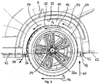
- the wheel housings 40 preferably enclose the wheels 36 over a circumference of more than 180° (cf. figure 3 ).
- a water mirror is in 3 denoted by the reference numeral 62.
- the wheel housings 40 are preferably open, so that the outside view is free of the wheels 36 arranged therein.
- a rotation of the driven wheels 36a in the wheel housings 40 causes on the one hand Side 42 (when the vehicle 2 is driving forward, i.e.
- the wheels 36 protrude from the water by at least half their diameter, which is the case, for example, in figure 3 it can be seen where the water level 62 is arranged below the axis of rotation 34, so that optimal propulsion of the vehicle 2 is ensured by the rotation of the wheels 36a.
- the vehicle 2 When the model vehicle 2 transitions from land to water, it may be that the vehicle 2 is initially relatively deep in the water, in particular so deep that optimal propulsion is not provided by the rotation of the wheels 36a alone.
- the wheels 36a could initially be submerged in the water 62 to over half their diameter. Due to the rotation 44 of the driven wheels 36a immediately or even while the vehicle 2 enters the water and the water flow 54 thus generated in the wheel housings 40, the vehicle 2 is additionally raised within a very short time, so that the wheels 36a move further out again the water 62 protrude, in particular with at least half of their diameter. As a result, the particularly efficient propulsion of the model vehicle 2 in the water 62 is again possible solely through the wheels 36a.
- the running surface 50 and/or a side wall 64 at least of the drivable wheels 36a be designed with driven wheels 36a, the formation of the water flow 54 in the wheel well 40 to promote.
- the running surface 50 and/or the side wall 64 of at least the drivable wheels 36a can have profile elements 66 distributed over the circumference of the wheels 36a (cf. figure 4 ) with a surface extension transverse, preferably perpendicular, to a direction of rotation 44 of the driven wheels 36a and parallel to the axis of rotation 34.
- profile elements 66 act, for example, as wings or shovels and increase the amount of water 48, 58 conveyed into the wheel housings 40 and thus—since the volume in the wheel housings 40 or between the running surface 50 of the wheels 36a and the inner wall 52 of the wheel housings 40 is limited and remains essentially constant - the flow speed of the water flow 54 in the wheel housings 40.
- This leads to a particularly low pressure p 1 in the wheel housings 40 or to a particularly large pressure difference (p 2 - p 1 ) between the interior of the wheel housings 40 (Pressure p 1 ) and outside of the wheel housings 40 (pressure p 2 ) and finally to a particularly large additional lift 60.
- the profile elements 66 can improve the propulsion of the watercraft 2, since they are in the water, ie below the water level 62, like blades of a bucket wheel drive.
- the hollow housing 38 of the chassis 4 provides buoyancy when the model vehicle 2 is operated in the water with the wheels 36a stationary, so that the vehicle 2 floats.
- the housing 38 preferably contains some, particularly preferably all, electrical and/or electronic components of the vehicle 2 in order to protect them from moisture and from chemical and/or mechanical influences.
- the at least one electric motor 32, a control unit 68, a transmission 70 and/or at least one battery 76 for supplying energy to the at least one electric motor 32 and/or the control unit 68 is accommodated in a moisture-tight manner in the housing 38 of the chassis 4.
- the transmission 70 is preferably used to convert a relatively high speed of the electric motor 32 to a lower speed (but higher torque) of a driveshaft 72 for the wheels 36a. Furthermore, the transmission 70 can compensate for an angular and/or vertical offset between a motor shaft 74 and the drive shaft 72 .
- the control unit 68 (cf. figure 6 ) comprises at least one circuit board 78 on which electrical and/or electronic components 80 can be attached and/or electrically contacted. For the purpose of making contact, it is proposed that corresponding conductor tracks (not shown) be formed on the printed circuit board 78 . Separate cables 82 can be provided for contacting the other electrical components (eg batteries 76 and electric motor 32) of the vehicle 2 .
- the control unit 68 includes a microprocessor (not shown) on which a computer program can run that is programmed to control and operate the model car 2 and executes the control or operating function when the program is processed on the microprocessor .
- the computer program to run through an operating cycle of the vehicle 2 after the model vehicle 2 has been switched on, which time-variably involves activation/deactivation of the electric motor 32, an adjustment of the speed of the electric motor 32, an adjustment of the steering of the model vehicle 2, etc includes.
- the at least one battery 76 is preferably designed as a chargeable accumulator. In particular, the use of a Lilon battery, a LiPo battery or a LiFePo4 battery is considered.
- the battery 76 is preferably arranged in a low point of the housing 38 so that the model vehicle 2 has the lowest possible center of gravity.
- the housing 38 of the chassis 4 is open at the top, so that the interior of the housing 38 can be freely accessed after the body 6 has been removed, for example for maintenance or repair purposes.
- the housing 38 has at least one with a cover 98 (cf. figure 5 ) moisture-tight closable access opening 100 (cf. figure 7 ).
- the body 6 or a part of it forms the cover 98 for the housing 38 and that after the body 6 has been attached to the chassis 4 or the housing 38, this is closed in a moisture-tight manner.
- the cover 98 can also be formed as a separate part, in which case the body 6 then has nothing to do with sealing the housing 38 in a moisture-tight manner.
- the housing 38 of the chassis 4 has at least one first upper access opening 100 which allows access to the interior of the housing 38 from above.
- the housing 38 can have at least a second lower access opening (not shown) which allows access into the interior of the housing 38 from below.
- Alternative or additional lidable access openings may also be provided on the side of the housing 38 .
- the entire housing 38 is hermetically sealed.
- the interior of the housing 38 can be divided into individual chambers 38a, 38b, which are preferably sealed off from one another in a moisture-tight manner (cf. figure 7 ), so that the electrical and/or electronic components 32, 68, 76 are arranged in different chambers 38a, 38b of the housing 38.
- the batteries 76 in their own chamber 38a in order to protect the other components 32, 68, 70 in the housing 38, which are arranged in one or more other chambers 38b, from heat, leaking battery acid or the like . to protect.
- Each chamber 38a, 38b is preferably assigned at least one access opening of its own, with or without a cover.
- All openings, such as top access opening 100, of housing 38 are preferably sealed by covers, such as top cover 98, to form a moisture-tight seal.
- covers such as top cover 98
- a seal can be provided between the cover 98 and the edge of the opening 100 .
- glue the cover 98 to the opening 100 with the glue being able to act as a seal at the same time.
- the cover 98 is preferably detachably fastened to the housing 38 by means of a snap or latching connection and/or at least one screw. Any other options for detachably or non-detachably attaching the cover 98 to the housing 38 are conceivable.
- At least one drive shaft 72 (cf. figure 6 ), which is assigned to at least one driven wheel 36a, is guided in a sealed manner through a receiving opening of the housing 38.
- a stuffing box for sealing purposes can be arranged in the receiving opening.
- the open Receiving openings for the drive shaft 72 in separate chambers inside the housing 38, which are separated from the other chambers.
- Receiving openings for the sealed passage of the drive shaft(s) 72 can also be provided in the partition walls between adjacent chambers.
- the wheels 36 each have a rim 84 made of a first material (e.g. hard plastic or metal) and a tire 86 made of another material (e.g. soft plastic, foam, rubber) mounted thereon.
- the wheels 36 in particular the tires 86, are made from a solid material (eg solid rubber or foam rubber).
- the wheels 36 have air-filled tires 86 made of rubber or soft plastic, which provide additional (slight) buoyancy when the model vehicle 2 is operated in water.
- air-filled tires 86 can provide shock absorption and suspension for the vehicle 2 . In this way, the sensitive electrical and/or electronic components 32, 68, 76 of the model vehicle 2 can be protected from mechanical influences (eg shocks, impacts, vibrations) or their effects.
- At least the driven wheels 36a each have a rim 84 with spokes 88, which extend in the radial direction from a hub 90 of the wheel 36, through which the axis of rotation 34 of the wheel 36 extends to a rim ring 92 on which the tire 86 of the wheel 36 is mounted, with at least some of the spokes 88 having a surface extension in the axial direction and in the axial direction over a side wall 64 of the mounted tire 86 or over a side wall of the Rim ring 92 protrude.
- the laterally protruding spokes 88 can act in the water like blades of a paddle wheel drive.
- the hollow housing 38 of the chassis 4 and the wheels 36 of the model vehicle 2 are designed in such a way and are coordinated in their respective shape and dimensions in such a way that when the model vehicle 2 is operated in the water, the wheels 36 are at most half their Diameter immerse in the water 62 (cf. figure 3 ).
- the driven wheels 36a protrude from the water 62 so that only a smaller portion of the wheels 36a are immersed in the water 62.
- the submerged portion of the wheels 36a is bounded by the lower arc of the tread 50 and the secant corresponding to the water level 62 when viewed from the side.
- the openings 42, 56 in the wheel housings 40 between the running surface 50 of the wheels 36 and the inner wall 52 of the wheel housings 40 it is not necessary for the openings 42, 56 in the wheel housings 40 between the running surface 50 of the wheels 36 and the inner wall 52 of the wheel housings 40 to be below the water level 62, since the driven wheels 36a also rotate 44 then pump water 48 into the wheel wells 40 and generate the water flow 54 therein when the openings 42, 56 in the wheel wells 40 are above the water level 62.
- the wheels 36b of the model vehicle 2 be mounted on the chassis 4 such that they can be steered about steering axes 102 (cf. figure 7 ).
- the steerable wheels 36b preferably allow the vehicle 2 to be steered when the model vehicle 2 is operated both on land and in the water.
- the steering axes 102 preferably run transversely, particularly preferably perpendicularly, to the axis of rotation 34 of the wheels 36b.
- the steering axles 102 preferably extend in the vertical direction or almost vertically, ie at an angle of a few degrees to the vertical.
- the steerable wheels 36b of the model vehicle 2 may or may not be simultaneously driven wheels 36a.
- the steerable wheels 36b each have a rim 84 with spokes 88 and a disk-shaped covering cap 104 for the spokes 88 (cf. figure 9 ) or with a disc 106 instead of spokes 88 (cf. figure 10 ) exhibit.
- the covering cap 104 is attached to the spokes 88, for example by means of gluing or by means of a clip connection.
- the disc 106 is preferably formed integrally with the remainder of the rim 84 .
- the cover cap 104 or the disk 106 has a radial surface extension and extends from a hub 90 of the wheel 36, through which the axis of rotation 34 of the wheel 36 runs, to the rim ring 92 on which the tire 86 of the wheel 36 is mounted. This has the advantage that the cover caps 104 or discs 106 of the steerable wheels 36b act as rudders when operating on water, and additional devices for changing the direction of travel 46 when operating on water can thereby be dispensed with.
- the steerable wheels 36b can be driven about the axes of rotation 34, so that when operating on water, the additional propulsion generated by the steerable wheels 36b is directed in a specific steering direction, which the model vehicle 2 then follows .
- the model vehicle 2 can have an on/off switch 94 accessible from the outside, preferably from above, via which the model vehicle 2 can be switched on and/or off (cf. figures 6 and 7 ). It is conceivable that the housing 38, at least in some areas, is guided so far in the direction of the outside of the model vehicle 2 that the on/off switch 94 can be arranged in this area 38a of the housing 38 (cf. figure 5 ). This has the advantage that the electrical components of the switch 94 are also arranged in the housing 38 and are protected from moisture, among other things. An actuating element 96 for actuating the switch 94 can be moved from the switch 94 through an opening in the body 6 be guided externally (cf. figures 1 and 5 ).
- the on/off switch 94 be arranged in the housing 38 of the chassis 4, with an actuating element 96 assigned to the on/off switch 94, via which a user of the model vehicle 2 can access the on/off switch 94 has protrudes through an opening in the body 6 or can be actuated through an opening in the body 6 from the outside.
- the at least one electric motor 32 is advantageously switched on automatically and the drivable wheels 36a are driven.
- the steerable wheels 36b are preferably brought into a desired steering position in advance, which is maintained during operation of the model vehicle 2 .
- the model vehicle 2 then drives continuously, for example, drives in a circle, for the duration of activation by the on/off switch 94 .
- the steerable wheels 36b can be varied dynamically while the vehicle 2 is driving, for example by means of control commands from the control unit 68. In this case, too, the vehicle 2 will travel continuously during operation, for example a continuous figure eight -shaped or a more complex ride.
- additional switches that can be actuated from the outside can be provided (not shown), via which, for example, the speed of the vehicle 2 can be set or an additional function of the vehicle 2 (e.g. a flashing light, a siren or an engine noise) can be activated.
- an additional function of the vehicle 2 e.g. a flashing light, a siren or an engine noise
- the model vehicle 2 has a remote control or RC (radio controlled) module 108 (cf. figure 6 ), which is preferably arranged in the housing 38 of the chassis 4.
- This remote control module 108 can be arranged, for example, on circuit board 78 of control unit 68 and connected to a radio antenna. It allows remote control of the model vehicle 2 via a suitable remote control (not shown).
- Various functions of the vehicle 2 can optionally be remote-controlled and other functions of the vehicle 2 can be preset, for example via switches. For example, it would be conceivable that the engine 32 of the vehicle 2 and a drive of the driven wheels 36a via a Switch 94 are turned on and a steering of the vehicle 2 is remote controlled. The drive and steering of the vehicle 2 are preferably remote-controlled. Additional functions of the vehicle 2 can optionally also be remotely controlled.
- the remote-controlled model vehicle 2 is preferably put into a stand-by mode by switching on the on/off switch 94 .
- the at least one electric motor 32 is only switched on via the RC module 108 and the drivable wheels 36a are driven by actuating a remote control (e.g. actuating an accelerator lever or a travel switch on the remote control).
- the remote-controlled steering of the vehicle 2 can take place, for example, via proportional servo motors or stepper motors.
- the RC module 108 includes a receiving unit for receiving radio signals from a suitable remote control, which transmits radio signals on an appropriate frequency and for the receiving unit of the RC module 108 to understand.
- the radio signals received contain commands which, for example, require propulsion in a specific direction 46 (forward or backward) and/or steering in a specific direction (left, right, straight ahead) and/or activation or deactivation of an additional function of the vehicle 2 cause.
- the RC module 108 can include a transmission unit for transmitting radio signals to the remote control.
- the radio signals include, in particular, feedback on the current operating status of the model vehicle 2 (e.g. speed, direction of travel, activation or deactivation of an additional function, a malfunction or the state of charge of the battery 76 of the vehicle 2).
- the RC module 108 is supplied with electrical energy from the battery 76 of the vehicle 2 .
- the RC module 108 communicates with the vehicle 2 control unit 68, is controlled by it and/or directs drive commands to the appropriate components of the model vehicle 2 (e.g. the electric motor 32, proportional servo or stepper motors, switches for activation/deactivation of additional functions) further.
Landscapes
- Toys (AREA)
Claims (14)
- Véhicule modèle (2) comprenant un châssis (4), au moins un moteur électrique (32), au moins quatre roues (36) montées sur le châssis (4) de manière à pouvoir tourner autour d'axes de rotation (34), dont au moins deux (36a) peuvent être entraînées autour de leurs axes de rotation (34) au moyen du au moins un moteur électrique (32), les roues entraînées (36a) assurant une propulsion du véhicule modèle (2) lors d'un fonctionnement du véhicule modèle (2) sur la terre ferme, et une carrosserie (6) qui est fixée au châssis (4), le châssis (4) comprenant un boîtier creux (38) qui, lors d'un fonctionnement du véhicule modèle (2) dans l'eau, génère une flottabilité suffisamment importante pour que le véhicule modèle (2) flotte dans l'eau, etune propulsion du véhicule modèle (2) dans l'eau est effectuée uniquement par les roues entraînées (36a) et le boîtier (38) et/ou la carrosserie (6) présente au moins pour chacune des roues entraînables (36a) un logement de roue (40) dans lequel est disposée la roue correspondante (36),caractérisé en ce quele au moins un logement de roue (40) est formé par le boîtier (38) et/ou la carrosserie (6),le boîtier (38) et/ou les roues (36) du véhicule modèle (2) sont conçus de telle sorte que, lorsque le véhicule modèle (2) fonctionne dans l'eau, les roues (36) s'enfoncent dans l'eau (62) au maximum avec la moitié de leur diamètre, etdans l'au moins un logement de roue (40), entre une surface de roulement (50) des roues entraînées (36a) et une paroi intérieure (52) de l'au moins un logement de roue (40), il règne, dans le courant d'eau, une pression (p1) plus faible que dans l'eau à l'extérieur de l'au moins un logement de roue (40).
- Véhicule modèle (2) selon la revendication 1, caractérisé en ce qu'une surface de roulement (50) et/ou une paroi latérale (64) d'au moins les roues entraînées (36a) est configurée pour favoriser la formation d'un courant d'eau (54) dans le logement de roue (40) lorsque les roues entraînées (36a) sont en mouvement.
- Véhicule modèle (2) selon la revendication 1 ou 2, caractérisé en ce que la surface de roulement (50) et/ou la paroi latérale (64) d'au moins les roues (36a) pouvant être entraînées présente des éléments profilés (66) répartis sur la périphérie des roues (36) avec une extension de surface transversale, de préférence perpendiculaire, à un sens de rotation (44) des roues entraînées (36a).
- Véhicule modèle (2) selon l'une des revendications 1 à 3, caractérisé en ce que le boîtier (38) du châssis (4) contient de manière étanche à l'humidité le au moins un moteur électrique (32), une unité de commande (68), un engrenage (70) et/ou au moins une batterie (76) pour l'alimentation en énergie du au moins un moteur électrique (32) et/ou de l'unité de commande (68).
- Véhicule modèle (2) selon l'une des revendications 1 à 4, caractérisé en ce que le boîtier (38) du châssis (4) présente au moins une ouverture d'accès (100) pouvant être fermée de manière étanche à l'humidité par un couvercle (98).
- Véhicule modèle (2) selon l'une des revendications 1 à 5, caractérisé en ce qu'au moins un arbre d'entraînement (72) associé à au moins une roue entraînée (36a) est guidée de manière étanche à travers une ouverture de réception du boîtier (38).
- Véhicule modèle (2) selon l'une des revendications 1 à 6, caractérisé en ce que les roues (36) comportent des pneumatiques (86) remplis d'air qui assurent une flottabilité supplémentaire lors d'un fonctionnement du véhicule modèle (2) dans l'eau.
- Véhicule modèle (2) selon l'une des revendications 1 à 7, caractérisé en ce qu'au moins les roues entraînées (36a) comportent chacune une jante (84) à rayons (88) s'étendant radialement à partir d'un moyeu (90) de la roue (36), par lequel passe l'axe de rotation (34) de la roue (36), jusqu'à un anneau de jante (92) sur lequel un pneumatique (86) de la roue (36) est monté, au moins certains des rayons (88) ayant une extension de surface dans la direction axiale et dépassant dans la direction axiale au-delà d'une paroi latérale (64) du pneumatique (86) monté.
- Véhicule modèle (2) selon l'une des revendications 1 à 8, caractérisé en ce qu'au moins deux des roues (36b) du véhicule modèle (2) sont montées sur le châssis (4) de manière à pouvoir être orientées autour d'axes de direction (102), de préférence les roues orientables (36b) permettant de diriger le véhicule modèle (2) lors d'un fonctionnement du véhicule modèle (2) aussi bien sur la terre ferme que dans l'eau.
- Véhicule modèle (2) selon la revendication 9, caractérisé en ce que les roues orientables (36b) présentent chacune une jante (84) avec des rayons (88) et un capuchon (104) en forme de disque pour les rayons (88) ou avec un disque (106) à la place des rayons (88), le capuchon (104) ou le disque (106) présente une extension de surface radiale et s'étend depuis un moyeu (90) de la roue (36b), par lequel passe l'axe de rotation (34) de la roue (36), jusqu'à un anneau de jante (92) sur lequel est monté un pneumatique (86) de la roue (36).
- Véhicule modèle selon l'une des revendications 1 à 10, caractérisé en ce que le véhicule modèle (2) comporte un interrupteur marche/arrêt (94) accessible de l'extérieur, de préférence par le haut, et permettant d'allumer et/ou d'éteindre le véhicule modèle (2).
- Véhicule modèle (2) selon la revendication 11, caractérisé en ce que l'interrupteur marche/arrêt (94) est disposé dans le boîtier (38) du châssis (4), un élément d'actionnement (94) associé à l'interrupteur marche/arrêt (94), par lequel un utilisateur du véhicule modèle (2) a accès à l'interrupteur marche/arrêt (94), dépassant par une ouverture dans la carrosserie (6) ou pouvant être actionné de l'extérieur par une ouverture dans la carrosserie (6).
- Véhicule modèle (2) selon la revendication 11 ou 12, caractérisé en ce qu'après l'activation de l'interrupteur marche/arrêt (94), le ou les moteurs électriques (32) sont automatiquement activés et les roues (36a) pouvant être entraînées sont entraînées.
- Véhicule modèle (2) selon l'une des revendications 1 à 13, caractérisé en ce que le véhicule modèle (2) comporte un module de télécommande (108), de préférence disposé dans le boîtier (38) du châssis (4).
Priority Applications (1)
| Application Number | Priority Date | Filing Date | Title |
|---|---|---|---|
| EP20174636.9A EP3909657B1 (fr) | 2020-05-14 | 2020-05-14 | Modèle réduit de véhicule destiné au fonctionnement sur terre et dans l'eau |
Applications Claiming Priority (1)
| Application Number | Priority Date | Filing Date | Title |
|---|---|---|---|
| EP20174636.9A EP3909657B1 (fr) | 2020-05-14 | 2020-05-14 | Modèle réduit de véhicule destiné au fonctionnement sur terre et dans l'eau |
Publications (2)
| Publication Number | Publication Date |
|---|---|
| EP3909657A1 EP3909657A1 (fr) | 2021-11-17 |
| EP3909657B1 true EP3909657B1 (fr) | 2022-06-29 |
Family
ID=70736692
Family Applications (1)
| Application Number | Title | Priority Date | Filing Date |
|---|---|---|---|
| EP20174636.9A Active EP3909657B1 (fr) | 2020-05-14 | 2020-05-14 | Modèle réduit de véhicule destiné au fonctionnement sur terre et dans l'eau |
Country Status (1)
| Country | Link |
|---|---|
| EP (1) | EP3909657B1 (fr) |
Families Citing this family (1)
| Publication number | Priority date | Publication date | Assignee | Title |
|---|---|---|---|---|
| CN121466612B (zh) * | 2026-01-09 | 2026-03-13 | 汕头市通德工艺制品有限公司 | 一种水陆两栖玩具装甲车 |
Family Cites Families (3)
| Publication number | Priority date | Publication date | Assignee | Title |
|---|---|---|---|---|
| US4652247A (en) * | 1980-02-14 | 1987-03-24 | Adolph E. Goldfarb | Amphibious self-powered toy vehicle with integrated four-wheel and steering-water-jet drive |
| KR910000337B1 (ko) * | 1988-03-08 | 1991-01-24 | 반도스포츠 주식회사 | 수륙양용 자동차 작동완구 |
| MX2009006715A (es) * | 2006-12-19 | 2009-06-30 | Mattel Inc | Vehiculo de juguete de tres ruedas. |
-
2020
- 2020-05-14 EP EP20174636.9A patent/EP3909657B1/fr active Active
Also Published As
| Publication number | Publication date |
|---|---|
| EP3909657A1 (fr) | 2021-11-17 |
Similar Documents
| Publication | Publication Date | Title |
|---|---|---|
| DE69203342T2 (de) | Spielfahrzeug. | |
| EP1187732B1 (fr) | Vehicule amphibie | |
| US5181478A (en) | Amphibious vehicle with retractable wheels | |
| DE69707023T2 (de) | Fahrspielzeug mit veränderlich positionierbaren Rädern | |
| DE102014115926A1 (de) | Antriebsmodul für ein Kraftfahrzeug und Kraftfahrzeug mit einem solchen Antriebsmodul | |
| DE2259751A1 (de) | Spielzeugfahrzeug | |
| DE69202150T2 (de) | Getriebe für ein Fahrspielzeug. | |
| DE212004000008U1 (de) | Fahrzeug mit Schneckenantrieb | |
| DE212022000259U1 (de) | Ein hybrides Flügel- und Rotor-Rückzugssystem für ein fliegendes Auto | |
| DE102008040751A1 (de) | Fernsteuerbares Luftkissenfahrzeug und Bausatz | |
| EP3909657B1 (fr) | Modèle réduit de véhicule destiné au fonctionnement sur terre et dans l'eau | |
| DE29722592U1 (de) | Spielzeugauto mit beweglichem vorderen Ende | |
| DE202020102716U1 (de) | Modellfahrzeug zum Betrieb an Land und im Wasser | |
| DE3109976A1 (de) | Erkundungs- und patrouillenfahrzeug | |
| DE112005003113T5 (de) | Antriebssystem für Modellflugzeug | |
| EP1954365B1 (fr) | Véhicule jouet | |
| DE1555453A1 (de) | Motorfahrzeug | |
| DE19707282A1 (de) | Vorrichtung zur Verstärkung des Bodendrucks eines Kraftradvorderrads | |
| DE202011100501U1 (de) | Rad für ein Wasserfahrzeug, und ein Wasserfahrzeug, das mit mindestens einem solchem Rad ausgestattet ist | |
| DE102022200667A1 (de) | Lenksäule für ein Kraftfahrzeug | |
| CN109017179A (zh) | 水陆两栖消防车 | |
| DE1250292C2 (de) | Antriebseinrichtung für Wasserfahrzeuge | |
| CN112840758A (zh) | 一种带旋耕的微型智能船型拖拉机 | |
| KR101793688B1 (ko) | 수륙 양용 장갑차 | |
| DE3901171C2 (fr) |
Legal Events
| Date | Code | Title | Description |
|---|---|---|---|
| PUAI | Public reference made under article 153(3) epc to a published international application that has entered the european phase |
Free format text: ORIGINAL CODE: 0009012 |
|
| STAA | Information on the status of an ep patent application or granted ep patent |
Free format text: STATUS: REQUEST FOR EXAMINATION WAS MADE |
|
| 17P | Request for examination filed |
Effective date: 20210510 |
|
| AK | Designated contracting states |
Kind code of ref document: A1 Designated state(s): AL AT BE BG CH CY CZ DE DK EE ES FI FR GB GR HR HU IE IS IT LI LT LU LV MC MK MT NL NO PL PT RO RS SE SI SK SM TR |
|
| B565 | Issuance of search results under rule 164(2) epc |
Effective date: 20201002 |
|
| GRAP | Despatch of communication of intention to grant a patent |
Free format text: ORIGINAL CODE: EPIDOSNIGR1 |
|
| STAA | Information on the status of an ep patent application or granted ep patent |
Free format text: STATUS: GRANT OF PATENT IS INTENDED |
|
| INTG | Intention to grant announced |
Effective date: 20220110 |
|
| GRAS | Grant fee paid |
Free format text: ORIGINAL CODE: EPIDOSNIGR3 |
|
| GRAA | (expected) grant |
Free format text: ORIGINAL CODE: 0009210 |
|
| STAA | Information on the status of an ep patent application or granted ep patent |
Free format text: STATUS: THE PATENT HAS BEEN GRANTED |
|
| AK | Designated contracting states |
Kind code of ref document: B1 Designated state(s): AL AT BE BG CH CY CZ DE DK EE ES FI FR GB GR HR HU IE IS IT LI LT LU LV MC MK MT NL NO PL PT RO RS SE SI SK SM TR |
|
| REG | Reference to a national code |
Ref country code: CH Ref legal event code: EP |
|
| REG | Reference to a national code |
Ref country code: AT Ref legal event code: REF Ref document number: 1500911 Country of ref document: AT Kind code of ref document: T Effective date: 20220715 |
|
| REG | Reference to a national code |
Ref country code: IE Ref legal event code: FG4D Free format text: LANGUAGE OF EP DOCUMENT: GERMAN |
|
| REG | Reference to a national code |
Ref country code: DE Ref legal event code: R096 Ref document number: 502020001289 Country of ref document: DE |
|
| REG | Reference to a national code |
Ref country code: LT Ref legal event code: MG9D |
|
| PG25 | Lapsed in a contracting state [announced via postgrant information from national office to epo] |
Ref country code: SE Free format text: LAPSE BECAUSE OF FAILURE TO SUBMIT A TRANSLATION OF THE DESCRIPTION OR TO PAY THE FEE WITHIN THE PRESCRIBED TIME-LIMIT Effective date: 20220629 Ref country code: NO Free format text: LAPSE BECAUSE OF FAILURE TO SUBMIT A TRANSLATION OF THE DESCRIPTION OR TO PAY THE FEE WITHIN THE PRESCRIBED TIME-LIMIT Effective date: 20220929 Ref country code: LT Free format text: LAPSE BECAUSE OF FAILURE TO SUBMIT A TRANSLATION OF THE DESCRIPTION OR TO PAY THE FEE WITHIN THE PRESCRIBED TIME-LIMIT Effective date: 20220629 Ref country code: HR Free format text: LAPSE BECAUSE OF FAILURE TO SUBMIT A TRANSLATION OF THE DESCRIPTION OR TO PAY THE FEE WITHIN THE PRESCRIBED TIME-LIMIT Effective date: 20220629 Ref country code: GR Free format text: LAPSE BECAUSE OF FAILURE TO SUBMIT A TRANSLATION OF THE DESCRIPTION OR TO PAY THE FEE WITHIN THE PRESCRIBED TIME-LIMIT Effective date: 20220930 Ref country code: FI Free format text: LAPSE BECAUSE OF FAILURE TO SUBMIT A TRANSLATION OF THE DESCRIPTION OR TO PAY THE FEE WITHIN THE PRESCRIBED TIME-LIMIT Effective date: 20220629 Ref country code: BG Free format text: LAPSE BECAUSE OF FAILURE TO SUBMIT A TRANSLATION OF THE DESCRIPTION OR TO PAY THE FEE WITHIN THE PRESCRIBED TIME-LIMIT Effective date: 20220929 |
|
| REG | Reference to a national code |
Ref country code: NL Ref legal event code: MP Effective date: 20220629 |
|
| PG25 | Lapsed in a contracting state [announced via postgrant information from national office to epo] |
Ref country code: RS Free format text: LAPSE BECAUSE OF FAILURE TO SUBMIT A TRANSLATION OF THE DESCRIPTION OR TO PAY THE FEE WITHIN THE PRESCRIBED TIME-LIMIT Effective date: 20220629 Ref country code: LV Free format text: LAPSE BECAUSE OF FAILURE TO SUBMIT A TRANSLATION OF THE DESCRIPTION OR TO PAY THE FEE WITHIN THE PRESCRIBED TIME-LIMIT Effective date: 20220629 |
|
| PG25 | Lapsed in a contracting state [announced via postgrant information from national office to epo] |
Ref country code: NL Free format text: LAPSE BECAUSE OF FAILURE TO SUBMIT A TRANSLATION OF THE DESCRIPTION OR TO PAY THE FEE WITHIN THE PRESCRIBED TIME-LIMIT Effective date: 20220629 |
|
| PG25 | Lapsed in a contracting state [announced via postgrant information from national office to epo] |
Ref country code: SM Free format text: LAPSE BECAUSE OF FAILURE TO SUBMIT A TRANSLATION OF THE DESCRIPTION OR TO PAY THE FEE WITHIN THE PRESCRIBED TIME-LIMIT Effective date: 20220629 Ref country code: SK Free format text: LAPSE BECAUSE OF FAILURE TO SUBMIT A TRANSLATION OF THE DESCRIPTION OR TO PAY THE FEE WITHIN THE PRESCRIBED TIME-LIMIT Effective date: 20220629 Ref country code: RO Free format text: LAPSE BECAUSE OF FAILURE TO SUBMIT A TRANSLATION OF THE DESCRIPTION OR TO PAY THE FEE WITHIN THE PRESCRIBED TIME-LIMIT Effective date: 20220629 Ref country code: PT Free format text: LAPSE BECAUSE OF FAILURE TO SUBMIT A TRANSLATION OF THE DESCRIPTION OR TO PAY THE FEE WITHIN THE PRESCRIBED TIME-LIMIT Effective date: 20221031 Ref country code: ES Free format text: LAPSE BECAUSE OF FAILURE TO SUBMIT A TRANSLATION OF THE DESCRIPTION OR TO PAY THE FEE WITHIN THE PRESCRIBED TIME-LIMIT Effective date: 20220629 Ref country code: EE Free format text: LAPSE BECAUSE OF FAILURE TO SUBMIT A TRANSLATION OF THE DESCRIPTION OR TO PAY THE FEE WITHIN THE PRESCRIBED TIME-LIMIT Effective date: 20220629 |
|
| PG25 | Lapsed in a contracting state [announced via postgrant information from national office to epo] |
Ref country code: PL Free format text: LAPSE BECAUSE OF FAILURE TO SUBMIT A TRANSLATION OF THE DESCRIPTION OR TO PAY THE FEE WITHIN THE PRESCRIBED TIME-LIMIT Effective date: 20220629 Ref country code: IS Free format text: LAPSE BECAUSE OF FAILURE TO SUBMIT A TRANSLATION OF THE DESCRIPTION OR TO PAY THE FEE WITHIN THE PRESCRIBED TIME-LIMIT Effective date: 20221029 |
|
| REG | Reference to a national code |
Ref country code: DE Ref legal event code: R097 Ref document number: 502020001289 Country of ref document: DE |
|
| PG25 | Lapsed in a contracting state [announced via postgrant information from national office to epo] |
Ref country code: AL Free format text: LAPSE BECAUSE OF FAILURE TO SUBMIT A TRANSLATION OF THE DESCRIPTION OR TO PAY THE FEE WITHIN THE PRESCRIBED TIME-LIMIT Effective date: 20220629 |
|
| PG25 | Lapsed in a contracting state [announced via postgrant information from national office to epo] |
Ref country code: DK Free format text: LAPSE BECAUSE OF FAILURE TO SUBMIT A TRANSLATION OF THE DESCRIPTION OR TO PAY THE FEE WITHIN THE PRESCRIBED TIME-LIMIT Effective date: 20220629 Ref country code: CZ Free format text: LAPSE BECAUSE OF FAILURE TO SUBMIT A TRANSLATION OF THE DESCRIPTION OR TO PAY THE FEE WITHIN THE PRESCRIBED TIME-LIMIT Effective date: 20220629 |
|
| PLBE | No opposition filed within time limit |
Free format text: ORIGINAL CODE: 0009261 |
|
| STAA | Information on the status of an ep patent application or granted ep patent |
Free format text: STATUS: NO OPPOSITION FILED WITHIN TIME LIMIT |
|
| 26N | No opposition filed |
Effective date: 20230330 |
|
| P01 | Opt-out of the competence of the unified patent court (upc) registered |
Effective date: 20230524 |
|
| REG | Reference to a national code |
Ref country code: CH Ref legal event code: PL |
|
| PG25 | Lapsed in a contracting state [announced via postgrant information from national office to epo] |
Ref country code: MC Free format text: LAPSE BECAUSE OF FAILURE TO SUBMIT A TRANSLATION OF THE DESCRIPTION OR TO PAY THE FEE WITHIN THE PRESCRIBED TIME-LIMIT Effective date: 20220629 |
|
| REG | Reference to a national code |
Ref country code: BE Ref legal event code: MM Effective date: 20230531 |
|
| PG25 | Lapsed in a contracting state [announced via postgrant information from national office to epo] |
Ref country code: MC Free format text: LAPSE BECAUSE OF FAILURE TO SUBMIT A TRANSLATION OF THE DESCRIPTION OR TO PAY THE FEE WITHIN THE PRESCRIBED TIME-LIMIT Effective date: 20220629 Ref country code: LU Free format text: LAPSE BECAUSE OF NON-PAYMENT OF DUE FEES Effective date: 20230514 Ref country code: LI Free format text: LAPSE BECAUSE OF NON-PAYMENT OF DUE FEES Effective date: 20230531 Ref country code: IT Free format text: LAPSE BECAUSE OF FAILURE TO SUBMIT A TRANSLATION OF THE DESCRIPTION OR TO PAY THE FEE WITHIN THE PRESCRIBED TIME-LIMIT Effective date: 20220629 Ref country code: CH Free format text: LAPSE BECAUSE OF NON-PAYMENT OF DUE FEES Effective date: 20230531 |
|
| REG | Reference to a national code |
Ref country code: IE Ref legal event code: MM4A |
|
| PG25 | Lapsed in a contracting state [announced via postgrant information from national office to epo] |
Ref country code: IE Free format text: LAPSE BECAUSE OF NON-PAYMENT OF DUE FEES Effective date: 20230514 |
|
| PG25 | Lapsed in a contracting state [announced via postgrant information from national office to epo] |
Ref country code: IE Free format text: LAPSE BECAUSE OF NON-PAYMENT OF DUE FEES Effective date: 20230514 |
|
| PG25 | Lapsed in a contracting state [announced via postgrant information from national office to epo] |
Ref country code: BE Free format text: LAPSE BECAUSE OF NON-PAYMENT OF DUE FEES Effective date: 20230531 |
|
| PG25 | Lapsed in a contracting state [announced via postgrant information from national office to epo] |
Ref country code: BG Free format text: LAPSE BECAUSE OF FAILURE TO SUBMIT A TRANSLATION OF THE DESCRIPTION OR TO PAY THE FEE WITHIN THE PRESCRIBED TIME-LIMIT Effective date: 20220629 |
|
| PG25 | Lapsed in a contracting state [announced via postgrant information from national office to epo] |
Ref country code: BG Free format text: LAPSE BECAUSE OF FAILURE TO SUBMIT A TRANSLATION OF THE DESCRIPTION OR TO PAY THE FEE WITHIN THE PRESCRIBED TIME-LIMIT Effective date: 20220629 |
|
| PGFP | Annual fee paid to national office [announced via postgrant information from national office to epo] |
Ref country code: DE Payment date: 20250521 Year of fee payment: 6 |
|
| PGFP | Annual fee paid to national office [announced via postgrant information from national office to epo] |
Ref country code: GB Payment date: 20250527 Year of fee payment: 6 |
|
| PGFP | Annual fee paid to national office [announced via postgrant information from national office to epo] |
Ref country code: FR Payment date: 20250528 Year of fee payment: 6 |
|
| PGFP | Annual fee paid to national office [announced via postgrant information from national office to epo] |
Ref country code: AT Payment date: 20250721 Year of fee payment: 5 |
|
| PG25 | Lapsed in a contracting state [announced via postgrant information from national office to epo] |
Ref country code: CY Free format text: LAPSE BECAUSE OF FAILURE TO SUBMIT A TRANSLATION OF THE DESCRIPTION OR TO PAY THE FEE WITHIN THE PRESCRIBED TIME-LIMIT; INVALID AB INITIO Effective date: 20200514 |
|
| PG25 | Lapsed in a contracting state [announced via postgrant information from national office to epo] |
Ref country code: HU Free format text: LAPSE BECAUSE OF FAILURE TO SUBMIT A TRANSLATION OF THE DESCRIPTION OR TO PAY THE FEE WITHIN THE PRESCRIBED TIME-LIMIT; INVALID AB INITIO Effective date: 20200514 |
|
| PG25 | Lapsed in a contracting state [announced via postgrant information from national office to epo] |
Ref country code: TR Free format text: LAPSE BECAUSE OF FAILURE TO SUBMIT A TRANSLATION OF THE DESCRIPTION OR TO PAY THE FEE WITHIN THE PRESCRIBED TIME-LIMIT Effective date: 20220629 |
|
| PG25 | Lapsed in a contracting state [announced via postgrant information from national office to epo] |
Ref country code: SI Free format text: LAPSE BECAUSE OF FAILURE TO SUBMIT A TRANSLATION OF THE DESCRIPTION OR TO PAY THE FEE WITHIN THE PRESCRIBED TIME-LIMIT Effective date: 20220629 |