EP3909669A1 - Procédé de préparation d'une couche de support polymère poreuse et ses utilisations - Google Patents
Procédé de préparation d'une couche de support polymère poreuse et ses utilisations Download PDFInfo
- Publication number
- EP3909669A1 EP3909669A1 EP20174809.2A EP20174809A EP3909669A1 EP 3909669 A1 EP3909669 A1 EP 3909669A1 EP 20174809 A EP20174809 A EP 20174809A EP 3909669 A1 EP3909669 A1 EP 3909669A1
- Authority
- EP
- European Patent Office
- Prior art keywords
- polymer
- dope
- graphene
- solution
- membrane
- Prior art date
- Legal status (The legal status is an assumption and is not a legal conclusion. Google has not performed a legal analysis and makes no representation as to the accuracy of the status listed.)
- Withdrawn
Links
- 238000000034 method Methods 0.000 title claims abstract description 56
- 238000002360 preparation method Methods 0.000 title claims abstract description 20
- 229910021389 graphene Inorganic materials 0.000 claims abstract description 137
- OKTJSMMVPCPJKN-UHFFFAOYSA-N Carbon Chemical compound [C] OKTJSMMVPCPJKN-UHFFFAOYSA-N 0.000 claims abstract description 126
- 239000012528 membrane Substances 0.000 claims abstract description 111
- 229920000642 polymer Polymers 0.000 claims abstract description 91
- 239000002904 solvent Substances 0.000 claims abstract description 61
- 238000005191 phase separation Methods 0.000 claims abstract description 16
- KFZMGEQAYNKOFK-UHFFFAOYSA-N Isopropanol Chemical compound CC(C)O KFZMGEQAYNKOFK-UHFFFAOYSA-N 0.000 claims description 147
- 239000000654 additive Substances 0.000 claims description 47
- 230000000996 additive effect Effects 0.000 claims description 47
- SECXISVLQFMRJM-UHFFFAOYSA-N N-Methylpyrrolidone Chemical compound CN1CCCC1=O SECXISVLQFMRJM-UHFFFAOYSA-N 0.000 claims description 46
- 239000004695 Polyether sulfone Substances 0.000 claims description 41
- 229920006393 polyether sulfone Polymers 0.000 claims description 41
- 229920000036 polyvinylpyrrolidone Polymers 0.000 claims description 40
- 239000001267 polyvinylpyrrolidone Substances 0.000 claims description 40
- 235000013855 polyvinylpyrrolidone Nutrition 0.000 claims description 40
- 239000011148 porous material Substances 0.000 claims description 37
- 238000005345 coagulation Methods 0.000 claims description 22
- 230000015271 coagulation Effects 0.000 claims description 22
- XLYOFNOQVPJJNP-UHFFFAOYSA-N water Substances O XLYOFNOQVPJJNP-UHFFFAOYSA-N 0.000 claims description 21
- 238000005266 casting Methods 0.000 claims description 20
- 239000002202 Polyethylene glycol Substances 0.000 claims description 18
- 229920001223 polyethylene glycol Polymers 0.000 claims description 18
- XBDQKXXYIPTUBI-UHFFFAOYSA-N dimethylselenoniopropionate Natural products CCC(O)=O XBDQKXXYIPTUBI-UHFFFAOYSA-N 0.000 claims description 16
- LFQSCWFLJHTTHZ-UHFFFAOYSA-N Ethanol Chemical compound CCO LFQSCWFLJHTTHZ-UHFFFAOYSA-N 0.000 claims description 13
- PEDCQBHIVMGVHV-UHFFFAOYSA-N Glycerine Chemical compound OCC(O)CO PEDCQBHIVMGVHV-UHFFFAOYSA-N 0.000 claims description 12
- ZMXDDKWLCZADIW-UHFFFAOYSA-N N,N-Dimethylformamide Chemical compound CN(C)C=O ZMXDDKWLCZADIW-UHFFFAOYSA-N 0.000 claims description 12
- 239000003795 chemical substances by application Substances 0.000 claims description 11
- 238000005530 etching Methods 0.000 claims description 11
- 239000004372 Polyvinyl alcohol Substances 0.000 claims description 9
- 229920002451 polyvinyl alcohol Polymers 0.000 claims description 9
- IAZDPXIOMUYVGZ-UHFFFAOYSA-N Dimethylsulphoxide Chemical compound CS(C)=O IAZDPXIOMUYVGZ-UHFFFAOYSA-N 0.000 claims description 8
- 229920003171 Poly (ethylene oxide) Polymers 0.000 claims description 8
- 230000009477 glass transition Effects 0.000 claims description 8
- 239000003960 organic solvent Substances 0.000 claims description 8
- 235000019260 propionic acid Nutrition 0.000 claims description 8
- IUVKMZGDUIUOCP-BTNSXGMBSA-N quinbolone Chemical compound O([C@H]1CC[C@H]2[C@H]3[C@@H]([C@]4(C=CC(=O)C=C4CC3)C)CC[C@@]21C)C1=CCCC1 IUVKMZGDUIUOCP-BTNSXGMBSA-N 0.000 claims description 8
- 229930195733 hydrocarbon Natural products 0.000 claims description 5
- 150000002430 hydrocarbons Chemical class 0.000 claims description 5
- 229920002492 poly(sulfone) Polymers 0.000 claims description 5
- JNYAEWCLZODPBN-JGWLITMVSA-N (2r,3r,4s)-2-[(1r)-1,2-dihydroxyethyl]oxolane-3,4-diol Chemical compound OC[C@@H](O)[C@H]1OC[C@H](O)[C@H]1O JNYAEWCLZODPBN-JGWLITMVSA-N 0.000 claims description 4
- YEJRWHAVMIAJKC-UHFFFAOYSA-N 4-Butyrolactone Chemical compound O=C1CCCO1 YEJRWHAVMIAJKC-UHFFFAOYSA-N 0.000 claims description 4
- FGUUSXIOTUKUDN-IBGZPJMESA-N C1(=CC=CC=C1)N1C2=C(NC([C@H](C1)NC=1OC(=NN=1)C1=CC=CC=C1)=O)C=CC=C2 Chemical compound C1(=CC=CC=C1)N1C2=C(NC([C@H](C1)NC=1OC(=NN=1)C1=CC=CC=C1)=O)C=CC=C2 FGUUSXIOTUKUDN-IBGZPJMESA-N 0.000 claims description 4
- NWGKJDSIEKMTRX-AAZCQSIUSA-N Sorbitan monooleate Chemical compound CCCCCCCC\C=C/CCCCCCCC(=O)OC[C@@H](O)[C@H]1OC[C@H](O)[C@H]1O NWGKJDSIEKMTRX-AAZCQSIUSA-N 0.000 claims description 4
- 239000004094 surface-active agent Substances 0.000 claims description 4
- 229920012266 Poly(ether sulfone) PES Polymers 0.000 claims description 3
- 238000000926 separation method Methods 0.000 abstract description 8
- 238000007873 sieving Methods 0.000 abstract description 7
- 229910052739 hydrogen Inorganic materials 0.000 abstract description 2
- 239000007789 gas Substances 0.000 description 50
- 239000010410 layer Substances 0.000 description 49
- 229960004592 isopropanol Drugs 0.000 description 44
- 239000010408 film Substances 0.000 description 28
- RYGMFSIKBFXOCR-UHFFFAOYSA-N Copper Chemical compound [Cu] RYGMFSIKBFXOCR-UHFFFAOYSA-N 0.000 description 20
- 239000011889 copper foil Substances 0.000 description 17
- 230000008569 process Effects 0.000 description 13
- 238000001878 scanning electron micrograph Methods 0.000 description 12
- 239000013047 polymeric layer Substances 0.000 description 11
- 239000004205 dimethyl polysiloxane Substances 0.000 description 9
- 239000000203 mixture Substances 0.000 description 9
- 229920000435 poly(dimethylsiloxane) Polymers 0.000 description 9
- 230000015572 biosynthetic process Effects 0.000 description 7
- 230000007547 defect Effects 0.000 description 6
- 239000002356 single layer Substances 0.000 description 6
- 230000001965 increasing effect Effects 0.000 description 5
- 238000005259 measurement Methods 0.000 description 5
- 239000000701 coagulant Substances 0.000 description 4
- 238000002474 experimental method Methods 0.000 description 4
- 239000002184 metal Substances 0.000 description 4
- 229910052751 metal Inorganic materials 0.000 description 4
- 238000001556 precipitation Methods 0.000 description 4
- 239000007787 solid Substances 0.000 description 4
- 239000000758 substrate Substances 0.000 description 4
- LCPVQAHEFVXVKT-UHFFFAOYSA-N 2-(2,4-difluorophenoxy)pyridin-3-amine Chemical compound NC1=CC=CN=C1OC1=CC=C(F)C=C1F LCPVQAHEFVXVKT-UHFFFAOYSA-N 0.000 description 3
- XDTMQSROBMDMFD-UHFFFAOYSA-N Cyclohexane Chemical compound C1CCCCC1 XDTMQSROBMDMFD-UHFFFAOYSA-N 0.000 description 3
- OKKJLVBELUTLKV-UHFFFAOYSA-N Methanol Chemical compound OC OKKJLVBELUTLKV-UHFFFAOYSA-N 0.000 description 3
- 239000004693 Polybenzimidazole Substances 0.000 description 3
- VYPSYNLAJGMNEJ-UHFFFAOYSA-N Silicium dioxide Chemical compound O=[Si]=O VYPSYNLAJGMNEJ-UHFFFAOYSA-N 0.000 description 3
- 229910052802 copper Inorganic materials 0.000 description 3
- 239000010949 copper Substances 0.000 description 3
- 230000003247 decreasing effect Effects 0.000 description 3
- 238000011161 development Methods 0.000 description 3
- 238000001035 drying Methods 0.000 description 3
- 230000000694 effects Effects 0.000 description 3
- 238000007654 immersion Methods 0.000 description 3
- 239000000463 material Substances 0.000 description 3
- 239000012466 permeate Substances 0.000 description 3
- 229920003223 poly(pyromellitimide-1,4-diphenyl ether) Polymers 0.000 description 3
- 229920002480 polybenzimidazole Polymers 0.000 description 3
- 229920006254 polymer film Polymers 0.000 description 3
- CHQMHPLRPQMAMX-UHFFFAOYSA-L sodium persulfate Substances [Na+].[Na+].[O-]S(=O)(=O)OOS([O-])(=O)=O CHQMHPLRPQMAMX-UHFFFAOYSA-L 0.000 description 3
- 238000003786 synthesis reaction Methods 0.000 description 3
- 239000010409 thin film Substances 0.000 description 3
- 238000012546 transfer Methods 0.000 description 3
- 239000004593 Epoxy Substances 0.000 description 2
- CBENFWSGALASAD-UHFFFAOYSA-N Ozone Chemical compound [O-][O+]=O CBENFWSGALASAD-UHFFFAOYSA-N 0.000 description 2
- -1 Polydimethylsiloxane Polymers 0.000 description 2
- 239000004642 Polyimide Substances 0.000 description 2
- 150000001298 alcohols Chemical class 0.000 description 2
- 230000008901 benefit Effects 0.000 description 2
- 239000000919 ceramic Substances 0.000 description 2
- 238000012512 characterization method Methods 0.000 description 2
- 238000005229 chemical vapour deposition Methods 0.000 description 2
- 239000011248 coating agent Substances 0.000 description 2
- 238000000576 coating method Methods 0.000 description 2
- 230000000052 comparative effect Effects 0.000 description 2
- 239000008367 deionised water Substances 0.000 description 2
- 229910021641 deionized water Inorganic materials 0.000 description 2
- 239000012456 homogeneous solution Substances 0.000 description 2
- 239000007788 liquid Substances 0.000 description 2
- 238000002156 mixing Methods 0.000 description 2
- 230000000877 morphologic effect Effects 0.000 description 2
- 230000037361 pathway Effects 0.000 description 2
- 229920001721 polyimide Polymers 0.000 description 2
- 230000002787 reinforcement Effects 0.000 description 2
- 238000004528 spin coating Methods 0.000 description 2
- 230000008093 supporting effect Effects 0.000 description 2
- 238000012360 testing method Methods 0.000 description 2
- 238000005406 washing Methods 0.000 description 2
- 239000010457 zeolite Substances 0.000 description 2
- GNFTZDOKVXKIBK-UHFFFAOYSA-N 3-(2-methoxyethoxy)benzohydrazide Chemical compound COCCOC1=CC=CC(C(=O)NN)=C1 GNFTZDOKVXKIBK-UHFFFAOYSA-N 0.000 description 1
- UFHFLCQGNIYNRP-UHFFFAOYSA-N Hydrogen Chemical compound [H][H] UFHFLCQGNIYNRP-UHFFFAOYSA-N 0.000 description 1
- PXHVJJICTQNCMI-UHFFFAOYSA-N Nickel Chemical compound [Ni] PXHVJJICTQNCMI-UHFFFAOYSA-N 0.000 description 1
- XOJVVFBFDXDTEG-UHFFFAOYSA-N Norphytane Natural products CC(C)CCCC(C)CCCC(C)CCCC(C)C XOJVVFBFDXDTEG-UHFFFAOYSA-N 0.000 description 1
- 229910021536 Zeolite Inorganic materials 0.000 description 1
- 238000001994 activation Methods 0.000 description 1
- 239000003462 bioceramic Substances 0.000 description 1
- 238000009529 body temperature measurement Methods 0.000 description 1
- 229910052799 carbon Inorganic materials 0.000 description 1
- 230000008859 change Effects 0.000 description 1
- 238000006243 chemical reaction Methods 0.000 description 1
- 238000004891 communication Methods 0.000 description 1
- 238000012733 comparative method Methods 0.000 description 1
- 239000000356 contaminant Substances 0.000 description 1
- 230000001419 dependent effect Effects 0.000 description 1
- HNPSIPDUKPIQMN-UHFFFAOYSA-N dioxosilane;oxo(oxoalumanyloxy)alumane Chemical compound O=[Si]=O.O=[Al]O[Al]=O HNPSIPDUKPIQMN-UHFFFAOYSA-N 0.000 description 1
- 238000009826 distribution Methods 0.000 description 1
- 238000005516 engineering process Methods 0.000 description 1
- 229920006335 epoxy glue Polymers 0.000 description 1
- 239000012510 hollow fiber Substances 0.000 description 1
- 239000001257 hydrogen Substances 0.000 description 1
- 230000001939 inductive effect Effects 0.000 description 1
- 229910010272 inorganic material Inorganic materials 0.000 description 1
- 239000011147 inorganic material Substances 0.000 description 1
- 230000003993 interaction Effects 0.000 description 1
- 238000011835 investigation Methods 0.000 description 1
- 238000004519 manufacturing process Methods 0.000 description 1
- 230000007246 mechanism Effects 0.000 description 1
- 238000012986 modification Methods 0.000 description 1
- 230000004048 modification Effects 0.000 description 1
- 238000001728 nano-filtration Methods 0.000 description 1
- 238000010587 phase diagram Methods 0.000 description 1
- 238000001020 plasma etching Methods 0.000 description 1
- 238000009832 plasma treatment Methods 0.000 description 1
- 229920005597 polymer membrane Polymers 0.000 description 1
- 239000000047 product Substances 0.000 description 1
- 230000003014 reinforcing effect Effects 0.000 description 1
- 230000000717 retained effect Effects 0.000 description 1
- 238000013341 scale-up Methods 0.000 description 1
- 238000007789 sealing Methods 0.000 description 1
- 239000000377 silicon dioxide Substances 0.000 description 1
- 239000007858 starting material Substances 0.000 description 1
- 239000000126 substance Substances 0.000 description 1
- 230000003319 supportive effect Effects 0.000 description 1
- 238000007740 vapor deposition Methods 0.000 description 1
Images


Classifications
-
- B—PERFORMING OPERATIONS; TRANSPORTING
- B01—PHYSICAL OR CHEMICAL PROCESSES OR APPARATUS IN GENERAL
- B01D—SEPARATION
- B01D67/00—Processes specially adapted for manufacturing semi-permeable membranes for separation processes or apparatus
- B01D67/0002—Organic membrane manufacture
- B01D67/0009—Organic membrane manufacture by phase separation, sol-gel transition, evaporation or solvent quenching
- B01D67/0011—Casting solutions therefor
- B01D67/00111—Polymer pretreatment in the casting solutions
-
- B—PERFORMING OPERATIONS; TRANSPORTING
- B01—PHYSICAL OR CHEMICAL PROCESSES OR APPARATUS IN GENERAL
- B01D—SEPARATION
- B01D67/00—Processes specially adapted for manufacturing semi-permeable membranes for separation processes or apparatus
- B01D67/0002—Organic membrane manufacture
- B01D67/0009—Organic membrane manufacture by phase separation, sol-gel transition, evaporation or solvent quenching
- B01D67/0016—Coagulation
- B01D67/00165—Composition of the coagulation baths
-
- B—PERFORMING OPERATIONS; TRANSPORTING
- B01—PHYSICAL OR CHEMICAL PROCESSES OR APPARATUS IN GENERAL
- B01D—SEPARATION
- B01D67/00—Processes specially adapted for manufacturing semi-permeable membranes for separation processes or apparatus
- B01D67/0079—Manufacture of membranes comprising organic and inorganic components
- B01D67/00791—Different components in separate layers
-
- B—PERFORMING OPERATIONS; TRANSPORTING
- B01—PHYSICAL OR CHEMICAL PROCESSES OR APPARATUS IN GENERAL
- B01D—SEPARATION
- B01D69/00—Semi-permeable membranes for separation processes or apparatus characterised by their form, structure or properties; Manufacturing processes specially adapted therefor
- B01D69/12—Composite membranes; Ultra-thin membranes
-
- B—PERFORMING OPERATIONS; TRANSPORTING
- B01—PHYSICAL OR CHEMICAL PROCESSES OR APPARATUS IN GENERAL
- B01D—SEPARATION
- B01D71/00—Semi-permeable membranes for separation processes or apparatus characterised by the material; Manufacturing processes specially adapted therefor
- B01D71/02—Inorganic material
- B01D71/021—Carbon
- B01D71/0211—Graphene or derivates thereof
-
- B—PERFORMING OPERATIONS; TRANSPORTING
- B01—PHYSICAL OR CHEMICAL PROCESSES OR APPARATUS IN GENERAL
- B01D—SEPARATION
- B01D71/00—Semi-permeable membranes for separation processes or apparatus characterised by the material; Manufacturing processes specially adapted therefor
- B01D71/06—Organic material
- B01D71/44—Polymers obtained by reactions only involving carbon-to-carbon unsaturated bonds, not provided for in a single one of groups B01D71/26-B01D71/42
- B01D71/441—Polyvinylpyrrolidone
-
- B—PERFORMING OPERATIONS; TRANSPORTING
- B01—PHYSICAL OR CHEMICAL PROCESSES OR APPARATUS IN GENERAL
- B01D—SEPARATION
- B01D71/00—Semi-permeable membranes for separation processes or apparatus characterised by the material; Manufacturing processes specially adapted therefor
- B01D71/06—Organic material
- B01D71/52—Polyethers
- B01D71/521—Aliphatic polyethers
- B01D71/5211—Polyethylene glycol or polyethyleneoxide
-
- B—PERFORMING OPERATIONS; TRANSPORTING
- B01—PHYSICAL OR CHEMICAL PROCESSES OR APPARATUS IN GENERAL
- B01D—SEPARATION
- B01D2256/00—Main component in the product gas stream after treatment
- B01D2256/16—Hydrogen
-
- B—PERFORMING OPERATIONS; TRANSPORTING
- B01—PHYSICAL OR CHEMICAL PROCESSES OR APPARATUS IN GENERAL
- B01D—SEPARATION
- B01D2256/00—Main component in the product gas stream after treatment
- B01D2256/18—Noble gases
-
- B—PERFORMING OPERATIONS; TRANSPORTING
- B01—PHYSICAL OR CHEMICAL PROCESSES OR APPARATUS IN GENERAL
- B01D—SEPARATION
- B01D2257/00—Components to be removed
- B01D2257/50—Carbon oxides
- B01D2257/504—Carbon dioxide
-
- B—PERFORMING OPERATIONS; TRANSPORTING
- B01—PHYSICAL OR CHEMICAL PROCESSES OR APPARATUS IN GENERAL
- B01D—SEPARATION
- B01D2323/00—Details relating to membrane preparation
- B01D2323/15—Use of additives
- B01D2323/218—Additive materials
- B01D2323/2182—Organic additives
- B01D2323/21839—Polymeric additives
- B01D2323/2185—Polyethylene glycol
-
- B—PERFORMING OPERATIONS; TRANSPORTING
- B01—PHYSICAL OR CHEMICAL PROCESSES OR APPARATUS IN GENERAL
- B01D—SEPARATION
- B01D2323/00—Details relating to membrane preparation
- B01D2323/15—Use of additives
- B01D2323/218—Additive materials
- B01D2323/2182—Organic additives
- B01D2323/21839—Polymeric additives
- B01D2323/2187—Polyvinylpyrolidone
-
- B—PERFORMING OPERATIONS; TRANSPORTING
- B01—PHYSICAL OR CHEMICAL PROCESSES OR APPARATUS IN GENERAL
- B01D—SEPARATION
- B01D2323/00—Details relating to membrane preparation
- B01D2323/64—Use of a temporary support
-
- B—PERFORMING OPERATIONS; TRANSPORTING
- B01—PHYSICAL OR CHEMICAL PROCESSES OR APPARATUS IN GENERAL
- B01D—SEPARATION
- B01D53/00—Separation of gases or vapours; Recovering vapours of volatile solvents from gases; Chemical or biological purification of waste gases, e.g. engine exhaust gases, smoke, fumes, flue gases, aerosols
- B01D53/22—Separation of gases or vapours; Recovering vapours of volatile solvents from gases; Chemical or biological purification of waste gases, e.g. engine exhaust gases, smoke, fumes, flue gases, aerosols by diffusion
- B01D53/228—Separation of gases or vapours; Recovering vapours of volatile solvents from gases; Chemical or biological purification of waste gases, e.g. engine exhaust gases, smoke, fumes, flue gases, aerosols by diffusion characterised by specific membranes
-
- B—PERFORMING OPERATIONS; TRANSPORTING
- B01—PHYSICAL OR CHEMICAL PROCESSES OR APPARATUS IN GENERAL
- B01D—SEPARATION
- B01D71/00—Semi-permeable membranes for separation processes or apparatus characterised by the material; Manufacturing processes specially adapted therefor
- B01D71/06—Organic material
- B01D71/66—Polymers having sulfur in the main chain, with or without nitrogen, oxygen or carbon only
- B01D71/68—Polysulfones; Polyethersulfones
Definitions
- the present invention pertains generally to the field of porous polymers, in particular by non-solvent induced phase separation and resulting membranes thereof, notably in the context of support layers.
- Single-layer graphene membranes are regarded as the ultimate membrane materials for separation applications not only because they are single atom thick but also because of their higher thermal and chemical stability and flexibility that is uncharacteristic for an inorganic material ( Jiang et al., 2009, Nano Lett., 9 (12), 4019-4024 ; Koenig et al., 2012, Nat. Nanotechnol. 7 (11), 728-732 ; Celebi et al., 2014, Science, 344 (6181), 289-292 ) .
- Large-scale roll-to-roll synthesis of graphene on copper foil via chemical vapor deposition has already been demonstrated a decade ago and its transfer onto non-porous substrates has been well-established ( Bae et al., 2010, Nat.
- Non-solvent induced phase separation is a well-established technique for obtaining a porous polymer structure ( Baker, R. W.
- the NIPS reaction system uses a ternary composition, usually including a polymer, a solvent and a non-solvent.
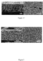
- the NIPS process immersion precipitation starts by mixing at least a polymer and a solvent to form an initial homogeneous solution (dope solution). Then, the dope solution is cast as a thin film on a support or extruded through a die to generate the membrane shapes such as flat sheets or hollow fibers ( Wang et al., 2013, Curr. Opin. Chem. Eng., 2, 229-237 ) as schematized on Fig. 1A .
- PES polysulfone
- PES polyethersulfone
- PI polyimides
- the polymer solution which they used for casting had a composition of 10-20% PES in N-methyl-2-pyrrolidone (NMP) with isopropylalcohol (IPA) added as an additive. Water at room temperature was used as the non-solvent. Kidambi et al. also used a similar composition (10- 16 wt.% PES, 1-2 wt.% IPA and 70 - 82 wt.% NMP) with water at room temperature as the non-solvent for preparing the porous graphene support ( Kidambi et al., 2018, ACS Appl. Mater. Interfaces, 10 (12), 10369-10378 ; Karnik et al., 2018, Adv. Mater. 2018, 30 (49), 1804977 ).
- the present invention is based on the unexpected finding of a process that allows obtaining a supportive polymeric layer on a graphene layer with suitable mechanical properties for ensuring a robust support, while maintaining suitable gas sieving properties.
- a general object of this invention is to provide an efficient method of preparation of a gas filter comprising a supported graphene membrane that can be easily handled without inducing cracks and defects.
- One of the specific objects of this invention is to provide an efficient method of preparation of a supported graphene membrane having gas permeation characteristics similar to that expected from the intrinsic defects of single-layer graphene.
- Another of the specific objects of this invention is to provide a method for the preparation of a gas selective filter comprising a graphene membrane, which is cost effective, has good gas selectivity and high performance and to provide a gas selective filter comprising a polymer-supported graphene membrane with good mechanical resistance.
- said polymeric layer has sub-500 nm pores at the polymer-graphene interface (lower layer of the polymer layer), preferably sub-300 nm.
- He or H 2 sieving e.g. H 2 /CO 2 , H 2 /CH 4 , H 2 /N 2 separation.
- the obtained product in the form of a polymer-coated graphene membrane on sacrificial support is subjected to an etching step to remove the sacrificial support to obtain a free-standing polymer-coated graphene membrane.
- the free-standing polymer-coated graphene membrane is used for preparing a gas filter.
- Also disclosed herein is a gas selective filter wherein the graphene membrane is made with a method according to the invention.
- gas selective filter selecting H 2 and/or He from CO 2 or N 2 and from larger molecular weight hydrocarbons (e.g. C 2 H 4 ) comprising an assembly of graphene membranes according to the invention.
- larger molecular weight hydrocarbons e.g. C 2 H 4
- a gas selective filter comprising a membrane for gas separation, in particular for separating H 2 and/or He and/or CO 2 from N 2 and CH 4 or from larger molecular weight hydrocarbons (e.g. C 2 H 4 ).
- the H 2 permeance of the gas filter is from about 1 ⁇ 10 -8 to about 7.3 ⁇ 10 -7 mol m -2 s -1 Pa -1 (e.g. 10 -7 at 200 °C).
- the H 2 /N 2 selectivity of a gas filter according to the invention is up to 28.7.
- non-solvent induced phase separation refers to a process as described in Dong et al., 2018, Membranes, 8(2), 23 and as illustrated under Fig. 1A wherein a dope solution is obtained by mixing at least one polymer and a solvent to form an initial homogeneous solution. Then, the dope solution is cast as a thin film on a support (e.g. with a moving blade) or extruded through a die to generate the membrane shape on a solid support.
- a support e.g. with a moving blade
- the coated solid support goes into a coagulation bath containing a non-solvent or a poor solvent for the polymer, and therefore a phase separation takes place when the solvent exchanges into the non-solvent and precipitation occurs in the polymeric solution.
- Fig. 1B an illustration of a method for the preparation of a polymer-supported graphene membrane according to an embodiment of the invention.
- the illustrated method generally comprises the steps of: comprising the steps of:
- the dope solution may further comprise a further dope additive such as an alcohol or water wherein said further dope additive is at about 1 to about 4 wt% (e.g. 2%).
- the resulting polymer-coated graphene membrane may then be subjected to an etching step in an etching batch to remove the sacrificial support (step f) to obtain a free-standing polymer-coated graphene membrane (step g).
- the sacrificial support may be a copper foil or a Nickel foil.
- the etching batch comprises a sodium persulfate solution and the etching step f) is followed by washing in deionized water.
- the graphene membrane on a sacrificial support can be provided in the form of a single layer graphene on a copper foil, for example obtained by known chemical vapor deposition.
- the polymer with a glass transition temperature of about 200°C or higher may be polyethersulfone (PES) or polysulfone (PSf).
- the polymer is PES.
- the dope or casting solution may comprise a polymer with a glass transition temperature of about 200°C or higher at a concentration of about 8 to about 25 wt %.
- the dope or casting solution may comprise a polymer with a glass transition temperature of about 200°C or higher at a concentration of about 15 to about 25 wt%.
- the organic solvent used in the dope solution is a solvent of the polymer.
- the organic solvent may be selected from N-Methyl-2-pyrrolidone (NMP), Dimethylformamide (DMF), Dimethyl sulfoxide (DMSO) and ⁇ -Butyrolactone.
- the polymer is PES and the organic solvent is NMP.
- the dope additive is selected from a polyvinylpyrrolidone (PVP) and a polyethylene glycol (PEG).
- PVP polyvinylpyrrolidone
- PEG polyethylene glycol
- the dope additive is PVP.
- the dope additive is PEG.
- the dope additive is PEG and the dope solution comprises the dope additive at a concentration higher than 5 wt % up to about 65 wt%.
- the dope solution comprises the dope additive selected from a polymeric agent such as polyvinylpyrrolidone (PVP), a polyethylene glycol (PEG), polyvinyl alcohol (PVA) and polyethylene oxide (PEO) and non-polymeric agent such as glycerol, propionic acid (PA), surfactants such as sorbitan monoleate (Span-80) at a concentration higher than 5 wt % up to about 15 wt%.
- a polymeric agent such as polyvinylpyrrolidone (PVP), a polyethylene glycol (PEG), polyvinyl alcohol (PVA) and polyethylene oxide (PEO)
- non-polymeric agent such as glycerol, propionic acid (PA), surfactants such as sorbitan monoleate (Span-80) at a concentration higher than 5 wt % up to about 15 wt%.
- the molecular weight or the dope additive is from about 400 to about 400'000 g/mole, in particular from about 400 to about 8'500 g/mol, such as from about from 800 to about 8'500 g/mol, for example from about 1'000 g/mol to about 2'500 g/mol or from about 1'000 g/mol to about 8'500 g/mol, in particular from about 1'500 g/mol to about 8'000 g/mol. (e.g. 2'000 g/mol).
- the dope additive is PVP and the dope solution comprises the dope additive at a concentration higher than 5 wt % up to about 15 wt%.
- the dope solution is coated on the graphene membrane at a temperature between about 20 and 30 °C.
- the graphene membrane on sacrificial support is covered with the said polymer solution to form a regular polymer solution film on the top of the graphene membrane, said formed film having a thickness in the range 10 to 1'000 ⁇ m, typically from about 100-500 ⁇ m.
- the regular polymer solution film on the top of the graphene membrane may be formed by the removing the excess dope solution (e.g. using a casting blade).
- the polymer coated graphene membrane is placed on sacrificial support in a coagulation bath comprising a non-solvent to induce a non-solvent induced phase separation for about 1 hour.
- the dope additive is readily soluble in the non-solvent. This property is useful in obtaining a sufficient porosity in the polymer layer, especially in the skin layer (the very top layer of the polymer film).
- agents which increase the viscosity of the dope solution advantageously slow down the mass transfer of nonsolvent (from the coagulation bath) inside the polymer film for phase separation, and help in reducing pore coarsening leading to smaller pores in creating a kinetic hinderance.
- agents which increase the viscosity of the dope solution increase the thermodynamic instability of the system by moving it closer towards the binodal boundary of the phase diagram (thermodynamic enhancement) leading to higher porosity.
- the final porous morphology of the film is a function of trade-off between the kinetic hinderance and the thermodynamic enhancement.
- the presence of a dope additive proved to be critical for obtaining the combination of spongy structures and small pores on the polymer layer in the area of the polymer-graphene interface. This is important because the skin layer should be porous and not too dense otherwise the gas permeance will reduce and may be dominated by the skin layer.
- the dope additive is PVP having a MW of about from about 1'000 to about 8'500 g/mole (e.g. 8'000 g/mole).
- the dope additive is PEG having a MW of about from about 1'000 g/mol to about 2'500 g/mole. (e.g. 2'000 g/mol).
- the dope solution comprises PES and PVP in NMP.
- the dope solution comprises PES (e.g. from about 8 to about 25, for example, 16 wt.%) and PVP (e.g. from about 5 to about 15, for example, 10 wt.%) in NMP
- the dope solution further comprises at least one further additive, wherein said further additive is an alcohol, preferably isopropyl alcohol (IPA) or ethanol at about 1 to about 4 wt% (e.g. 2%).
- said further additive is an alcohol, preferably isopropyl alcohol (IPA) or ethanol at about 1 to about 4 wt% (e.g. 2%).
- the dope solution may comprise IPA at about 1 to about 4 wt % as further additive.
- the dope solution further comprises at least one further additive typically at about 1 to about 3 wt%.
- the coagulation bath is at a temperature between about 20 and 30 °C.
- the coagulation bath may comprise IPA at about 55 to about 100 wt.%.
- the coagulation bath is 100% IPA.
- the coagulation bath comprising the non-solvent may further comprise at least one further agent as a non-solvent additive such as alcohols such as ethanol, methanol.
- the free-standing polymer-coated graphene membrane obtained after the etching step f) is sealed (e.g. with an epoxy glue) on a metallic support on the side of the polymer layer, the graphene layer being on the other side to form a gas filter according to the invention.
- the metallic support comprises a metallic mesh in contact with the polymer layer, wherein said metallic mesh is placed against a solid metal piece.
- the metallic mesh acts as a physical reinforcement aiding the pressurization of the membrane of the gas filter.
- a gas selective filter comprising a graphene membrane and a porous polymeric support structure wherein said polymeric support is composed of a polymer with a glass transition temperature of about 200°C or higher and wherein the size of the pores of the polymeric support are sub-500 nm, preferably sub-300 nm at the polymer-graphene interface.
- a gas selective filter of the invention has a thickness of about 20-150 ⁇ m and comprises a graphene membrane and a porous polymeric support structure mechanically reinforcing the graphene membrane.
- the polymeric structure comprises interconnected pores.
- the polymeric structure has a porosity greater than 10%.
- the H 2 permeance of the polymer-supported graphene membrane of the invention is from about 1 ⁇ 10 -8 mol m -2 s -1 Pa -1 to about 7.3 ⁇ 10 -1 mol m -2 s -1 Pa - 1 (e.g. 10 -7 at 200 °C).
- a method and of the invention further advantageously provides useful starting materials for the preparation of membranes suitable for He and H 2 from larger molecules with a high efficiency at high temperature where a H 2 permeance reaching 303 gas permeation units with H 2 /CO 2 , H 2 /N 2 , and H 2 /CH 4 selectivities reaching 6.7, 28.7, and 22.1, respectively, at 150-200 °C.
- the state-of-the-art membranes for hydrogen sieving at high temperature are based on rigid polymers such as polybenzimidazole (PBI) ( Swihart et al., 2017, Energy Environ. Sci. 00, 1-3 ; Pesiri et al., 2003, J. Memb.
- the dope additive according to the invention allows the formation of pores in the skin layer since it dissolves readily in the non-solvent.
- the dope additive according to the invention increases the viscosity of the polymer solution which helps in hampering or reducing the formation of macrovoids.
- a further dope additive such as alcohols (e.g. IPA) or water allows to increase the thermodynamic instability of the dope solution and accelerate the phase inversion process.
- a further dope additive is used in the dope solution at a weight ratio between the polymer and said further dope additive from about 24:1 to about 6:1 (e.g. about 8:1).
- Example 1 Comparative methods of preparation of a porous PES layer (not from the invention)
- Asymmetric structures with finger-like macrovoids, typical for phase inversion of PES were observed when using a method as described in Quin et al., 2017, supra or Kidambi et al., 2018, supra as shown under Fig. 1C where a very thin layer of net like structure, at the bottom of macrovoids, supported the graphene film.
- the presence of the macrovoids is undesirable for a material for use as a support, in particular for graphene membranes as it collapses under pressurization and affects the reproducibility of the net like structure, often leading to formation of large micrometer sized openings.
- the effect of the nature of the non-solvent was tested using a polymer solution containing PES (16 wt%) and IPA at 2 wt% prepared in NMP as a dope solution at room temperature.
- a graphene membrane on the copper foil was covered with the said polymer solution (dope solution or also called casting solution) to form a regular polymer solution film on the top of the graphene membrane on the copper foil and removing the excess solution using a casting blade.
- the polymer solution was degassed in vacuum at room temperature to remove the bubbles in the casting solution.
- the typical wet-thickness used for the casting process was in the range 10 to 1'000 ⁇ m, typically from about 100-500 ⁇ m, for example 400 ⁇ m (e.g.
- the polymer coated graphene membrane on the copper foil was placed in a coagulation bath comprising a non-solvent to induce a non-solvent induced phase separation at room temperature for at least 1 hour.
- the resulting polymer-coated graphene membrane on the copper foil was collected from the coagulation bath.
- the obtained membrane was then dried under ambient conditions to remove the nonsolvent from the polymer layer.
- the sacrificial layer e.g. copper foil
- the structure obtained was intermediate between using only water or IPA as the non-solvent (at room temperature for example, macrovoids did not extend all the way till the polymer-graphene interface as in the case of pure water as non-solvent and the spongy structure height was not as much as that of pure IPA as non-solvent at RT).
- Example 2 Method of preparation of a porous PES layer for supporting a graphene membrane according to the invention using a dope additive
- a single layer graphene was prepared on copper foil using standard vapor deposition method ( Zhao et al., 2019, Science Advances, 5 (1), eaav1851 ; Huang et al., 2018, Nature Communications 2018, 9 (1), 2632 ).
- the following process was used to prepare a porous polymer as support of the graphene layer on the copper foil as described below:
- the resulting polymer-coated graphene membrane on sacrificial support is then collected from the coagulation bath.
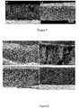
- the addition of PVP in the dope solution increases the porosity of the skin layer (top surface) thereby decreasing the resistance to the gas flow ( Fig. 4b compared to Fig. 4a ) ) and the macrovoids were restricted to the top few micrometers of the polymer layer ( Fig. 5a ).
- Increasing the thickness of the casting layer by using a casting blade with a larger air gap did not lead to an increase in the depth of the macrovoids, the macrovoids being still restricted to the top few micrometers while the remaining thickness has the desirable spongy like structure ( Fig. 5b ). Therefore, irrespective of the thickness, the macrovoids were restricted to the top few micrometers of the polymer layer.
- % PVP of MW 8'000 g/mol led to the presence of large macrovoids ( Fig. 6b ).
- Using a high molecular weight of PVP (MW 360'000 g/mole) instead PVP of a MW of 8'000 g/mole in the dope solution in presence of 2% of IPA leads to a completely spongy structure with no macrovoids at room temperature ( Fig. 6c,d ). Therefore, the quantity of the dope additive should be adapted for achieving a desired viscosity of the dope solution from about to about 0.5 to about 12.75 Pa s, more specifically from about 0.8-3 Pa s at 298 K.
- IPA concentration in the dope solution was also found to enlargen the pores and lead to more non-uniformity.
- the size of the pores at the polymer-graphene interface is dependent on the phase inversion kinetics.
- the phase inversion kinetics can be increased by using IPA at R.T. as the non-solvent instead of IPA at 0°C to obtain smaller pores near the graphene surface.
- % PVP in NMP with a casting layer thickness of 400 ⁇ m (10 MIL + 2 kapton tape thickness) and immersion in a coagulation bath of pure IPA at R.T. for one hour lead to a reproducible structure with a sponge like morphology with macrovoids restricted to the top few micrometers and the pores at the polymer-graphene interface were all below 300 nm ( Fig. 8 ).
- the macrovoids remain in the upper layers of the polymer and do not migrate towards the polymer-graphene interface even when the thickness of the layer of the casted solution increases.
- Fig. 3c and 8a represent identical phase inversion conditions according to the invention except for Fig.
- the thickness is higher, in this case, the macrovoids are limited to a small fraction of the total structure.
- Fig. 5 films prepared under identical conditions (16 wt% PES, 2 wt% IPA, 10 wt% PVP in NMP using IPA at room temperature as the coagulant) with different thicknesses (52 ⁇ m (Fig. 9a) and 137 ⁇ m (Fig. 9b) ), the macrovoids are still restricted to about 25 ⁇ m (25 ⁇ m (Fig. 9a) and 24 ⁇ m (Fig. 9b) ) in spite of the increased casting thickness.
- the PES/Graphene film was sealed on to a metal disc using epoxy. If desirable, the etching of the copper foil can also be done after sealing the copper/Graphene/PES membrane assembly with epoxy.
- a metal mesh was placed in between the PES layer and the metal disc, which acted as a physical reinforcement aiding the pressurization of the membrane.
- 2 wt. % Polydimethylsiloxane (PDMS) in cyclohexane was applied by spin coating at 1'500 rpm for 60 s. The spin coated layers were dried by keeping the membrane assembly at 75°C for 6 hours before testing.
- PDMS Polydimethylsiloxane
- the membranes were tested using a custom made Wicke-Kallenbach type setup.
- Pre-calibrated mass flow controllers (MFC) were used for delivering gases to the feed side.
- Ar gas was used as the sweep gas and the flow was maintained at 30 sccm using a dedicated MFC.
- the pressure in the feed side was controlled using a back-pressure regulator and the permeate side was maintained at atmospheric pressure. Gas tight seals were ensured using Viton O-rings.
- the permeate side composition was analyzed using a calibrated mass spectrometer (Hiden Analytical HPR-20). For high temperature measurements, the feed and the sweep lines were pre-heated and the entire module was placed in an oven.
- Pristine graphene on PES layer obtained according to a method of the invention as described under Example 2 was subjected to 3 s rf plasma at a pressure of 70 mTorr. No damage to the PES film was observed in SEM. Permeation measurements as described above revealed almost 3-fold increase in permeance after the plasma treatment (Table 2). For those experiments, a thin layer of polydimethylsiloxane (PDMS) was applied as a defect-sealing-layer since the PDMS solution effectively blocks the large defects of graphene if present, upon curing ( Li et al., 2014, Chem. Commun., 50 (24), 3214-3216 ; Chiu et al., 2011, J. Membr.
- PDMS polydimethylsiloxane
- the selectivities observed are much higher than the corresponding Knudsen selectivities (e.g. Knudsen selectivity of H 2 /N 2 is 3.75) and the permeance decreased in the order H 2 > CO 2 > CH 4 > N 2 .
- the H 2 transport is found to be highly activated with permeance increasing almost 4-fold from room temperature to 200°C. All these factors indicate a clear molecular sieving behavior arising from the polymer supported graphene membrane obtained by a method according to the invention.
Landscapes
- Chemical & Material Sciences (AREA)
- Chemical Kinetics & Catalysis (AREA)
- Engineering & Computer Science (AREA)
- Manufacturing & Machinery (AREA)
- Dispersion Chemistry (AREA)
- Inorganic Chemistry (AREA)
- Carbon And Carbon Compounds (AREA)
- Separation Using Semi-Permeable Membranes (AREA)
Priority Applications (1)
| Application Number | Priority Date | Filing Date | Title |
|---|---|---|---|
| EP20174809.2A EP3909669A1 (fr) | 2020-05-14 | 2020-05-14 | Procédé de préparation d'une couche de support polymère poreuse et ses utilisations |
Applications Claiming Priority (1)
| Application Number | Priority Date | Filing Date | Title |
|---|---|---|---|
| EP20174809.2A EP3909669A1 (fr) | 2020-05-14 | 2020-05-14 | Procédé de préparation d'une couche de support polymère poreuse et ses utilisations |
Publications (1)
| Publication Number | Publication Date |
|---|---|
| EP3909669A1 true EP3909669A1 (fr) | 2021-11-17 |
Family
ID=70738282
Family Applications (1)
| Application Number | Title | Priority Date | Filing Date |
|---|---|---|---|
| EP20174809.2A Withdrawn EP3909669A1 (fr) | 2020-05-14 | 2020-05-14 | Procédé de préparation d'une couche de support polymère poreuse et ses utilisations |
Country Status (1)
| Country | Link |
|---|---|
| EP (1) | EP3909669A1 (fr) |
Cited By (1)
| Publication number | Priority date | Publication date | Assignee | Title |
|---|---|---|---|---|
| EP4438163A1 (fr) * | 2023-03-27 | 2024-10-02 | Consejo Superior De Investigaciones Científicas | Membrane infiltrée d'un mélange polymère poreux |
Citations (1)
| Publication number | Priority date | Publication date | Assignee | Title |
|---|---|---|---|---|
| US20180345230A1 (en) * | 2017-06-06 | 2018-12-06 | Uop Llc | High permeance and high selectivity facilitated transport membranes for olefin/paraffin separations |
-
2020
- 2020-05-14 EP EP20174809.2A patent/EP3909669A1/fr not_active Withdrawn
Patent Citations (1)
| Publication number | Priority date | Publication date | Assignee | Title |
|---|---|---|---|---|
| US20180345230A1 (en) * | 2017-06-06 | 2018-12-06 | Uop Llc | High permeance and high selectivity facilitated transport membranes for olefin/paraffin separations |
Non-Patent Citations (35)
| Title |
|---|
| BAE ET AL., NAT. NANOTECHNOL., vol. 5, no. 8, 2010, pages 574 - 578 |
| BAKER, R. W.: "Membrane Technology and Applications", 2004, WILEY |
| BARZIN ET AL., J. MEMBR. SCI., vol. 325, no. 1, 2018, pages 92 - 97 |
| BARZIN J ET AL: "Correlation between macrovoid formation and the ternary phase diagram for polyethersulfone membranes prepared from two nearly similar solvents", JOURNAL OF MEMBRANE SCIENCE, ELSEVIER BV, NL, vol. 325, no. 1, 15 November 2008 (2008-11-15), pages 92 - 97, XP025506693, ISSN: 0376-7388, [retrieved on 20080710], DOI: 10.1016/J.MEMSCI.2008.07.003 * |
| BASU ET AL., MEMBR. SCI., vol. 362, no. 1, 2010, pages 478 - 487 |
| BRINKER ET AL., MRS PROC., vol. 368, 1994, pages 329 |
| CELEBI ET AL., SCIENCE, vol. 344, no. 6181, 2014, pages 289 - 292 |
| CHIU ET AL., J. MEMBR. SCI., vol. 377, no. 1, 2011, pages 182 - 190 |
| CHOI ET AL., J. AM. CHEM. SOC., vol. 132, 2010, pages 448 - 449 |
| DONG ET AL., MEMBRANES, vol. 8, no. 2, 2018, pages 23 |
| GASCON ET AL., CHEM. MATER., vol. 24, 2012, pages 2829 - 2844 |
| GUILLEN ET AL., IND. ENG. CHEM. RES, vol. 50, 2011, pages 3798 - 3817 |
| HE ET AL., ENERGY ENVIRON. SCI., vol. 12, no. 11, 2019, pages 3305 - 3312 |
| HUANG ET AL., NAT. COMMUN., vol. 9, no. 1, 2018, pages 2632 |
| HUANG ET AL., NATURE COMMUNICATIONS, 2018 |
| ISMAIL ET AL.: "Gas Separation Membranes: Polymeric and Inorganic", 2015, SPRINGER INTERNATIONAL PUBLISHING |
| ISMAIL ET AL: "Effect of additive contents on the performances and structural properties of asymmetric polyethersulfone (PES) nanofiltration membranes", SEPARATION AND PURIFICATION TECHNOLOGY, ELSEVIER SCIENCE, AMSTERDAM, NL, vol. 55, no. 1, 30 March 2007 (2007-03-30), pages 98 - 109, XP022009881, ISSN: 1383-5866, DOI: 10.1016/J.SEPPUR.2006.11.002 * |
| JIANG ET AL., NANO LETT., vol. 9, no. 12, 2009, pages 4019 - 4024 |
| KARNIK ET AL., ADV. MATER., vol. 30, no. 49, 2018, pages 1804977 |
| KIDAMBI ET AL., ACS APPL. MATER. INTERFACES, vol. 10, no. 12, 2018, pages 10369 - 10378 |
| KOBAYASHI ET AL., APPL. PHYS. LETT., vol. 102, no. 2, 2013, pages 023112 |
| KOENIG ET AL., NAT. NANOTECHNOL., vol. 7, no. 11, 2012, pages 728 - 732 |
| LEE, C ET AL., ACS NANO, vol. 8, no. 3, 2014, pages 2336 - 2344 |
| LI ET AL., CHEM. COMMUN., vol. 50, no. 24, 2014, pages 3214 - 3216 |
| PESIRI ET AL., J. MEMB. SCI., vol. 218, 2003, pages 11 - 18 |
| PIRAN R. KIDAMBI ET AL: "A Scalable Route to Nanoporous Large-Area Atomically Thin Graphene Membranes by Roll-to-Roll Chemical Vapor Deposition and Polymer Support Casting", ACS APPLIED MATERIALS & INTERFACES, vol. 10, no. 12, 19 March 2018 (2018-03-19), US, pages 10369 - 10378, XP055737778, ISSN: 1944-8244, DOI: 10.1021/acsami.8b00846 * |
| QIN ET AL., ACS APPL. MATER. INTERFACES, vol. 9, no. 11, 2017, pages 9239 - 9244 |
| RAMASUBRAMANIAN ET AL., AICHE J., vol. 59, 2013, pages 1033 - 1045 |
| SWIHART ET AL., ENERGY ENVIRON. SCI., vol. 00, 2017, pages 1 - 3 |
| TAN ET AL., POLYMERS, vol. 11, 2019, pages 1160 |
| WANG ET AL., CURR. OPIN. CHEM. ENG., vol. 2, 2013, pages 229 - 237 |
| WANG ET AL., J. MEMB. SCI., vol. 450, 2014, pages 425 - 432 |
| WANG ET AL., NAT. NANOTECHNOL., vol. 12, no. 6, 2017, pages 509 - 522 |
| YANZHE QIN ET AL: "Ultrafast Nanofiltration through Large-Area Single-Layered Graphene Membranes", ACS APPLIED MATERIALS & INTERFACES, vol. 9, no. 11, 13 March 2017 (2017-03-13), US, pages 9239 - 9244, XP055737777, ISSN: 1944-8244, DOI: 10.1021/acsami.7b00504 * |
| ZHAO ET AL., SCIENCE ADVANCES, vol. 5, no. 1, 2019, pages eaav1851 |
Cited By (2)
| Publication number | Priority date | Publication date | Assignee | Title |
|---|---|---|---|---|
| EP4438163A1 (fr) * | 2023-03-27 | 2024-10-02 | Consejo Superior De Investigaciones Científicas | Membrane infiltrée d'un mélange polymère poreux |
| WO2024199951A1 (fr) * | 2023-03-27 | 2024-10-03 | Consejo Superior De Investigaciones Científicas | Membrane poreuse infiltrée à base de mélange de polymères |
Similar Documents
| Publication | Publication Date | Title |
|---|---|---|
| Meng et al. | Compatibilizing hydrophilic and hydrophobic polymers via spray coating for desalination | |
| Deshmukh et al. | Effect of ethanol composition in water coagulation bath on morphology of PVDF hollow fibre membranes | |
| CN102131570B (zh) | 由有机聚硅氧烷共聚物制成的多孔膜 | |
| Ren et al. | Polyacrylonitrile supported thin film composite hollow fiber membranes for forward osmosis | |
| Shi et al. | Thin film composite membranes on ceramic for pervaporation dehydration of isopropanol | |
| Ho et al. | Fabrication of high-flux asymmetric polyethersulfone (PES) ultrafiltration membranes by nonsolvent induced phase separation process: Effects of H2O contents in the dope | |
| Suk et al. | Development of novel surface modified phase inversion membranes having hydrophobic surface-modifying macromolecule (nSMM) for vacuum membrane distillation | |
| US9533264B2 (en) | Composite membrane, method of manufacturing the same, separation membrane including the composite membrane, and water treatment device using the separation membrane | |
| EP0761291A1 (fr) | Solution polymérique de filage pour la préparation d'une membrane asymétrique à couche mince et intégrale | |
| US20130284023A1 (en) | Asymmetric Nanotube Containing Membranes | |
| Zuo et al. | The development of novel Nexar block copolymer/Ultem composite membranes for C2–C4 alcohols dehydration via pervaporation | |
| KR20120120989A (ko) | 다공성 실리콘 성형체의 제조 방법 | |
| Sinha et al. | Enhancement of hydrophilicity of poly (vinylidene fluoride-co-hexafluoropropylene)(PVDF-HFP) membrane using various alcohols as nonsolvent additives | |
| Liu et al. | High-flux thin-film composite polyelectrolyte hydrogel membranes for ethanol dehydration by pervaporation | |
| KR20160026070A (ko) | 기체분리막의 제조 방법 | |
| KR20110079140A (ko) | 다공성 멤브레인의 제조방법 및 그로부터 제조된 비대칭 다공성 멤브레인 | |
| EP3909669A1 (fr) | Procédé de préparation d'une couche de support polymère poreuse et ses utilisations | |
| US20230047835A1 (en) | Method for making porous filter membranes | |
| Zhou et al. | Homoporous membranes of block copolymers: Upscalable preparation by spray coating and performance boosting by quaternization | |
| Madaeni et al. | Preparation of polysulphone ultrafiltration membranes for milk concentration: effect of additives on morphology and performance | |
| US8518263B2 (en) | Method for fabrication of elastomeric asymmetric membranes from hydrophobic polymers | |
| KR100263333B1 (ko) | 다공성 탄소분자체 분리막의 제조방법 | |
| CN1218774C (zh) | 聚合物流体分离复合膜的制造方法 | |
| US20250033002A1 (en) | Porous Polybenzimidazole Membrane Supports for Composite Membranes | |
| Madaeni et al. | Preparation and characterization of PES and PA composite membranes for air separation at low pressures |
Legal Events
| Date | Code | Title | Description |
|---|---|---|---|
| PUAI | Public reference made under article 153(3) epc to a published international application that has entered the european phase |
Free format text: ORIGINAL CODE: 0009012 |
|
| STAA | Information on the status of an ep patent application or granted ep patent |
Free format text: STATUS: THE APPLICATION HAS BEEN PUBLISHED |
|
| AK | Designated contracting states |
Kind code of ref document: A1 Designated state(s): AL AT BE BG CH CY CZ DE DK EE ES FI FR GB GR HR HU IE IS IT LI LT LU LV MC MK MT NL NO PL PT RO RS SE SI SK SM TR |
|
| B565 | Issuance of search results under rule 164(2) epc |
Effective date: 20201019 |
|
| STAA | Information on the status of an ep patent application or granted ep patent |
Free format text: STATUS: REQUEST FOR EXAMINATION WAS MADE |
|
| 17P | Request for examination filed |
Effective date: 20220513 |
|
| RBV | Designated contracting states (corrected) |
Designated state(s): AL AT BE BG CH CY CZ DE DK EE ES FI FR GB GR HR HU IE IS IT LI LT LU LV MC MK MT NL NO PL PT RO RS SE SI SK SM TR |
|
| STAA | Information on the status of an ep patent application or granted ep patent |
Free format text: STATUS: THE APPLICATION IS DEEMED TO BE WITHDRAWN |
|
| 18D | Application deemed to be withdrawn |
Effective date: 20241203 |