EP3909683A1 - Utilisation d'un système d'entraînement pour un dispositif de broyage - Google Patents
Utilisation d'un système d'entraînement pour un dispositif de broyage Download PDFInfo
- Publication number
- EP3909683A1 EP3909683A1 EP21162853.2A EP21162853A EP3909683A1 EP 3909683 A1 EP3909683 A1 EP 3909683A1 EP 21162853 A EP21162853 A EP 21162853A EP 3909683 A1 EP3909683 A1 EP 3909683A1
- Authority
- EP
- European Patent Office
- Prior art keywords
- superposition
- gear
- electric motor
- shredding
- roller shaft
- Prior art date
- Legal status (The legal status is an assumption and is not a legal conclusion. Google has not performed a legal analysis and makes no representation as to the accuracy of the status listed.)
- Withdrawn
Links
Images


Classifications
-
- B—PERFORMING OPERATIONS; TRANSPORTING
- B02—CRUSHING, PULVERISING, OR DISINTEGRATING; PREPARATORY TREATMENT OF GRAIN FOR MILLING
- B02C—CRUSHING, PULVERISING, OR DISINTEGRATING IN GENERAL; MILLING GRAIN
- B02C18/00—Disintegrating by knives or other cutting or tearing members which chop material into fragments
- B02C18/06—Disintegrating by knives or other cutting or tearing members which chop material into fragments with rotating knives
- B02C18/16—Details
- B02C18/24—Drives
-
- B—PERFORMING OPERATIONS; TRANSPORTING
- B02—CRUSHING, PULVERISING, OR DISINTEGRATING; PREPARATORY TREATMENT OF GRAIN FOR MILLING
- B02C—CRUSHING, PULVERISING, OR DISINTEGRATING IN GENERAL; MILLING GRAIN
- B02C13/00—Disintegrating by mills having rotary beater elements ; Hammer mills
- B02C13/26—Details
- B02C13/30—Driving mechanisms
-
- B—PERFORMING OPERATIONS; TRANSPORTING
- B02—CRUSHING, PULVERISING, OR DISINTEGRATING; PREPARATORY TREATMENT OF GRAIN FOR MILLING
- B02C—CRUSHING, PULVERISING, OR DISINTEGRATING IN GENERAL; MILLING GRAIN
- B02C25/00—Control arrangements specially adapted for crushing or disintegrating
-
- F—MECHANICAL ENGINEERING; LIGHTING; HEATING; WEAPONS; BLASTING
- F16—ENGINEERING ELEMENTS AND UNITS; GENERAL MEASURES FOR PRODUCING AND MAINTAINING EFFECTIVE FUNCTIONING OF MACHINES OR INSTALLATIONS; THERMAL INSULATION IN GENERAL
- F16H—GEARING
- F16H3/00—Toothed gearings for conveying rotary motion with variable gear ratio or for reversing rotary motion
- F16H3/44—Toothed gearings for conveying rotary motion with variable gear ratio or for reversing rotary motion using gears having orbital motion
- F16H3/72—Toothed gearings for conveying rotary motion with variable gear ratio or for reversing rotary motion using gears having orbital motion with a secondary drive, e.g. regulating motor, in order to vary speed continuously
- F16H3/724—Toothed gearings for conveying rotary motion with variable gear ratio or for reversing rotary motion using gears having orbital motion with a secondary drive, e.g. regulating motor, in order to vary speed continuously using externally powered electric machines
Definitions
- the invention relates to the use of a drive system for a shredding device for shredding input material, preferably household waste, biowaste, bulky waste, mixed construction waste, wood materials, in particular waste wood, trunk wood, root wood and / or green cuttings and / or commercial waste, in particular goods that tend to be wrapped.
- the shredding device is also designed for processing or shredding tough material such as carpets (rolled goods), foam mattresses, PU foam linings, in particular from the automotive industry, rubber tires, etc.
- Material that tends to be wrapped can be longitudinally stable material, such as sheeting, branches with long twigs or the like.
- the present invention relates to a shredding device provided for shredding feed material, preferably household waste, biowaste, bulky waste, mixed construction waste, wood materials, in particular waste wood, trunk wood, root wood and / or green cuttings and / or commercial waste, with at least one roller shaft and one arranged on the roller shaft Shredding roller with shredding tools attached.
- the roller shaft can be driven by a drive system of the aforementioned type.
- a main drive of the drive system which causes a rotary movement of the roller shaft.
- the shredding tools arranged on the shredding drum interact with cutting tools and / or counter-shredding tools arranged on the housing and / or on counter-tool carriers.
- the interaction is designed in such a way that when the feed material enters the gap between the shredding tools and the counter-shredding tools, the input material is shredded by the rotation of the shredding roller.
- the object of the present invention is to avoid or at least substantially reduce the aforementioned disadvantages of the prior art.
- the roller shaft can be connected, preferably non-rotatably, to a shredding roller of the shredding device.
- a superposition gear of the drive system is coupled to the main drive, in particular with the superposition gear being designed to change the speed of the roller shaft, preferably continuously.
- the drive system further comprises a control device for detecting an overload of the shredding device.
- the control device can also preferably be designed in such a way that it enables continuous monitoring of the operating situation of the comminution device.
- An overload situation occurs in particular when the roller shaft threatens to stall or if the speed of the roller shaft threatens to decrease in such a way that a standstill of the shredding roller can be foreseen.
- Such an overload case occurs in particular when the feed material has jammed and / or wound up in the shredding device and thus - at least indirectly - the rotary movement of the roller shaft is blocked.
- an electric motor coupled to the control device for a superposition branch of the superposition gear is provided to drive the superposition gear.
- the control device is designed in such a way that the electric motor of the superposition branch is controlled by the control device in the event of an overload so that the superposition branch of the superposition gear causes a superposition movement in the superposition gear, so that the drive torque and / or the drive power from the main drive to the roller shaft is essentially prevented or at least prevented is reduced.
- the torque flow in particular is compensated to “zero”.
- the drive system has, in particular, a drive train which is composed at least of the main drive, the superposition gear arranged on the main drive and the roller shaft arranged on the superposition gear.
- the operating situation of the shredding device can be divided into three main cases, namely the normal operating situation, the load situation and the overload case.
- the roller shaft of the Main drive is driven and the shredding device shreds the feed material.
- the feed material is also comminuted, with the forces acting on the shredding roller leading to the speed of the shredding roller or roller shaft being reduced or being reduced compared to the speed in the normal operating situation and / or a higher torque on the main drive is applied.
- the overload situation can be distinguished from the load situation and the normal operating situation in particular in that, in the event of an overload, the roller shaft threatens to get stuck or the feed material has become wedged or jammed in the shredding device. Without the inventive intervention in the event of an overload, the roller shaft would be stationary or no longer rotate, since the drive torque transmission or application of torque from the main drive to the roller shaft continues and the main drive is overloaded. Ultimately, this leads to torques at the main drive that may be too high and can damage the machine.
- the electric motor can be viewed as an additional drive unit which ultimately makes it possible to prevent the interaction between the main drive and roller shaft in the event of an overload so that the power of the main drive can ultimately be "compensated” or also deflected.
- the torque, the rotational speed and / or the power from the main drive can be transmitted to the shredding roller at least essentially continuously and variably through the superposition gear.
- the variability is made possible by the overlay branch.
- an infinitely variable speed adjustment can be made possible, in particular with the respective behavior being able to be adapted to the material-specific input material. It is particularly advantageous that there is no undesired load on the main drive in the event of an overload, since the superposition gear, in particular when the roller shaft is at a standstill, can ensure compensation or compensation for the main drive.
- the control device can monitor the operating situation of the shredding roller so that, in the event of an overload, the main drive is not burdened by excessive torques applied to it will.
- a “stalling” of the main drive can be avoided in this way, that is, falling below a minimum speed or the forced standstill of the main drive.
- This not only protects the main drive, but can also ensure that the drive train can optimally adapt to the operating situation of the shredding device.
- damage to the comminution device in the event of an overload can be avoided.
- the longevity of the comminution device can be increased and the maintenance and operating costs of the comminution device can be reduced.
- the shredding device can also be used with less downtime, since the interruption or reduction of the drive torque transmission or application from the main drive to the roller shaft enables the shredding device to free itself from the blockage. In particular, no intervention by an outside operator is required. In the event of an overload, it can also be avoided that the main drive has to be switched off, so that a later, typically complex restart of the main drive is no longer necessary.
- the drive system according to the invention consequently enables high undesired loads or overloads to be avoided within the entire drive system.
- the electric motor used is characterized in that it can be operated with electrical energy, in particular in comparison to a hydraulic or internal combustion engine.
- electrical energy from renewable energy sources can be used to drive the electric motor, so that the electric motor can be operated in an environmentally friendly or resource-saving manner.
- control device can use a plurality of measuring devices which are arranged in the shredding device to monitor the operating situation and / or to detect an overload of the shredding device or an impending overload.
- a plurality of electrical sensors can be used that can detect the operating data of the shredding device, such as the current power, the current torque, the speed of the roller shaft, the electric motor, the main drive and / or the temperature at different points of the shredding device.
- additional physical transmitters such as pressure sensors, Position indicator for swivel angle or the like, absolutely necessary, so that the operating costs and the manufacturing costs of the shredding device equipped with the control device and the associated measuring devices can be reduced.
- the aforementioned means can certainly also be used.
- the feed material to be processed can also be taken into account in the control device for controlling and detecting the overload case.
- the operating situation of the shredding device can be monitored as a function of the feed material to be processed and the overload case can be mapped or determined in the control device as a function of the feed material to be processed.
- the optimal point in time for preventing the application of drive torque from the main drive to the roller shaft can thus be determined by the control device, in particular as a function of the input material to be processed and the resulting, assumed control operating situation.
- a comparison between the normal operating situation and the currently existing or detected operating situation of the shredding device can be used in the control device to detect or establish an overload situation.
- the control device can have corresponding adjusting means, via which settings can be made manually.
- the detection of an overload case also means that an impending overload case is recognized. According to the invention, such a specification is also understood as the detection of the overload case.
- the electric motor used for the superposition branch is also characterized by the fact that there is a particularly large speed working range that can be used advantageously to specify the superposition movement in the superposition gear, which ultimately leads to the application of drive torque from the main drive to the roller shaft in the overload case detected by the control device is prevented or reduced.
- the electric motor can also adapt to main drives that are operated with different powers or speeds.
- the main drive can thus be used at different speeds and / or powers, in particular depending on the material flow or feed material to be processed. Due to its high variability, the electric motor can adapt to different operating situations of the main drive. This enables that through the higher speed range of the electric superposition drive or the electric superposition branch of the entire machine configuration a significantly higher flexibility of use can be provided.
- the coupling and / or the interaction between the control device and the electric motor of the superposition branch is designed such that the control device controls the electric motor of the superposition branch in the event of an overload so that the direction of rotation of the roller shaft for a Reversing movement is reversed.
- a reversal of the direction of rotation of the roller shaft is to be understood such that a first direction of rotation of the roller shaft is specified by the main drive in regular operation. In the event of an overload, this first direction of rotation can be reversed by the superposition movement of the superposition branch given in the superposition gear, so that the roller shaft can ultimately run in the opposite direction to the normal operating situation.
- this reversing movement can only be specified for a limited range.
- the reversing movement enables the shredding device to release the blockage or the clamping itself, since the gap between the shredding tools and the counter-shredding tools can be enlarged. In this way, the clamped item can be released again, so that damage to the machine or the like due to the clamping can be avoided. In this way, the comminuting device can free itself again from a, in particular threatening, jamming.
- An impending jamming is to be understood in such a way that the control device can recognize a looming blockage by detecting the impending overload case or the overload case and stop the control operation of the shredding device by the predetermined superimposition movement in the superposition gear through the superposition branch.
- control device is designed in such a way that the electric motor of the superposition branch is further controlled by the control device to the effect that the speed and / or the power of the main drive during operation of the shredding device and in particular in the event of an overload at least remains essentially constant and / or lies in a tolerance range with deviations of a maximum of 10%.
- the tolerance range can be selected in such a way that the deviations fluctuate around the control operating parameter of the speed and / or power of the main drive in control mode.
- the superposition movement in the superposition gear enables the main drive to be operated with at least essentially constant speed and / or power, with the drive torque and / or the drive power from the main drive to the roller shaft being prevented or at least substantially prevented at least in the case of superimposition .
- the main drive or the control of the main drive is preferably not or hardly influenced by the operating situation of the comminuting device and in particular by the case of an overload of the comminuting device.
- the main drive would stall if the speed of the main drive is reduced to such an extent that the main drive is switched off. Such a behavior of the main drive can be avoided by operating the main drive at an at least substantially constant speed.
- the speed of the main drive is preferably between 1000 and 3000 rpm, preferably between 1300 and 2000 rpm, in particular between 1500 to 1800 rpm.
- the rotational speed of the roller shaft results when the drive torque is transmitted from the main drive to the roller shaft.
- the speed of the main drive is selected as a function of the speed of the roller shaft to be achieved and as a function of the translation of the superposition gear. According to the invention it has been found that the result of the comminution process can be optimized with speeds in the aforementioned order of magnitude.
- the control device is preferably designed to monitor the torque, the power and / or the speed of the electric motor of the superposition branch.
- the control device can determine whether the overload occurs.
- the control device is designed to monitor the torque, the power and / or the speed of the main drive. It can be provided that if the torque and / or power rise too high and / or the speed of the main drive drops too much - which ultimately deviates from the behavior in normal operation - the overload case is detected by the control device.
- the torque and / or the power of the main drive would in any case increase if the shredding device is jammed or threatens to jam.
- the speed of the main drive drops, for example, even to a standstill. Due to the increasing torque requirement of the main drive and / or the falling speed, an emerging blockage or jamming in the shredding device can be recognized.
- control device can also be designed to monitor the speed of the roller shaft.
- the speed of the roller shaft would in any case be reduced if an impending jamming or blockage occurs or is detected in the comminuting device.
- at least one or a plurality of measuring devices can be assigned to the control device, which measure the torque, the speed and / or the power of the main drive and / or the electric motor and / or the torque and / or the The speed and / or the performance of the shredding roller and / or the roller shaft are monitored.
- Activation of the electric motor can cause the superposition movement in the superposition gear.
- the superposition gear is preferably a planetary superposition gear.
- a planetary superposition gear enables the superposition movement in the event of an overload through the superposition branch.
- the superposition branch can be assigned to the superposition gear or act on the superposition gear, wherein the superposition with the superposition branch can be made possible by the superposition gear as such.
- the planetary superposition gear can also be referred to as a planetary gear.
- the planetary superposition gear enables a compact gear form of the superposition gear and ultimately a three-shaft gear.
- One shaft can be assigned to the drive, a further shaft to the output (shredding roller or roller shaft) and a third shaft, which is connected to the superposition branch.
- the planetary superposition gear can have a sun gear, at least one planet gear cooperating with the sun gear and a ring gear cooperating with the at least one planet gear.
- a plurality of planetary gears is provided which are connected to one another via a planetary gear carrier - also called a planetary gear web.
- the roller shaft is preferably arranged on the planetary gear carrier. Alternatively or additionally, it can also be provided that the roller shaft is arranged on at least one planet gear.
- the main drive can be connected to the sun gear or be arranged attacking the sun gear and drive the sun gear. It can thus be provided that there is an at least substantially constant or permanent rotation (that is to say a rotation at at least substantially constant speed) of the sun gear during operation of the comminuting device.
- the sun gear preferably transmits the rotary movement to the planet gears and thus to the planet gear carrier, which in turn can lead to a rotation of the roller shaft.
- the ring gear is preferably arranged coupled to the superimposition branch and / or the electric motor and left in a rotationally fixed manner in normal operation. In the event of an overload, this application of drive torque is transferred from the sun gear to the planet gear and / or to the planet gear carrier at least substantially reduced or prevented by the superimposition movement.
- the electric motor of the superposition branch is connected, in particular directly, to the ring gear.
- the ring gear, on which the electric motor designed as an additional drive unit is connected can be part of the superposition branch of the superposition gear.
- the superposition movement of the superposition branch can thus be caused by a rotation of the ring gear.
- the rotation of the ring gear can prevent or at least substantially reduce the application of drive torque from the sun gear to the at least one planet gear and / or to the planet gear carrier by the superposition movement. In this way, the torque flow can be compensated to "zero".
- the ring gear rotates at such a high speed that the direction of rotation of the roller shaft is reversed - in particular due to the superposition movement achieved by the ring gear in the superposition gear.
- the ring gear in normal operation - that is, not in the event of an overload - the ring gear is designed to be stationary or held (that is, it is braked). In this way, the ring gear in particular cannot cause any superposition movement in the superposition gear during normal operation, so that an at least approximately exclusive application of torque or torque transmission from the sun gear (which is driven by the main drive) to the planetary gear carrier (on which the roller shaft is arranged) takes place to drive the roller shaft .
- the electric motor of the superposition branch is designed as a brake with a variable braking effect.
- the electric motor is designed to hold the ring gear in place during normal operation of the shredding device.
- the electric motor or the superposition branch arranged on the ring gear can enable the ring gear to come to a standstill during the regular operation of the comminution device.
- the electric motor is consequently also operated during normal operation, in particular not only switched on in the event of an overload. An at least substantially constant operation of the electric motor can thus be provided during operation of the comminution device.
- the design of the electric motor of the superposition branch as a brake is preferably provided in such a way that the function of a mechanical holding brake is present for the standstill of the ring gear.
- the brake extends the axis of rotation of the superimposed motor, that is to say of the electric motor.
- a further braking means is also at least essentially directly connected to the electric motor, which enables the electric motor to be designed as a “brake with a variable braking effect”.
- This braking means can be designed as a mechanical holding brake.
- the further braking means is not a friction brake.
- the mechanical holding brake or the braking means can bring about an adaptation of the speed of the ring gear, in particular through the variable braking effect.
- the further braking means can, in particular in relation to a release element of the brake, be closable without external energy supply and / or without energy and / or without current, in particular by spring pressure. This is particularly preferred for emergency operation - that is, if the regulation or control device fails - or in the event of an overload.
- the ventilation element can furthermore preferably be operated electrically.
- control device is designed in such a way that, in the event of an overload, the electric motor is activated in such a way that it interacts with the ring gear in such a way that the ring gear can move, in particular by reducing the braking effect of the electric motor on the ring gear and / or that the speed of the ring gear is increased, so that the reversal of the direction of rotation of the roller shaft for the reversing movement is effected.
- the electric motor interacts with the braking means and / or the superposition branch in such a way that the braking effect is reduced in the event of an overload on the ring gear, so that a superposition movement - caused by rotation of the ring gear - can be made possible.
- the speed of the ring gear is increased in such a way that this reversal takes place.
- the electric motor can cause a standstill and an enabled movement of the ring gear can be controlled, which can ultimately cause a superposition movement in the superposition gear, which can serve at least substantially to prevent the application of drive torque from the sun gear to the planetary gear carrier.
- the advantage of the electric motor is that it can be quickly adapted to different operating situations and, in particular, is continuously adjustable.
- the electric motor and / or the controllability of the braking function of the electric motor can enable a quick and flexible reaction to the respective operating situation of the comminution device. In particular, it is possible to react promptly to changes in rotational speed and / or increases in torque on the roller shaft, which can occur as a result of the operation of the shredding device.
- the regulation by the control device via the interaction between the electric motor acting as a brake, the main drive and the roller shaft is a process that can react in particular to the overload case or is designed to avoid such.
- the control device is particularly preferably designed in such a way that the, in particular kinematic, speed specification for the superimposition branch takes place at least essentially continuously during the operation of the comminution device.
- This specification for the speed for the superimposition input for example for the speed of the ring gear to be maintained (a speed of 0 rpm can also be specified - that is, a standstill of the ring gear, which is specified in particular during normal operation) then leads, at least depending on the load Main process, to corresponding counter and / or braking torques at the superimposition input.
- the braking energy required for this which can be made available at the superposition input as a result of the load, can be recovered, in particular fed back in, with the aim of energy recovery. In particular, this enables energy-efficient operation of the comminution device to be ensured.
- an additional braking device connected to the ring gear can be provided for holding the ring gear; in particular, the additional braking device is preferably a mechanical brake Friction brake, formed.
- the additional braking device can be operated independently of the electric motor.
- the additional braking device is preferably coupled to the control device in such a way that, in the event of an overload, the additional braking device is decoupled from the ring gear and / or the braking power is reduced or switched off. This enables a movement of the ring gear to be ensured by the action of the electric motor on the superimposition branch and thus on the ring gear. The additional braking device can then no longer brake the ring gear.
- the additional braking device can be designed so that it can be released hydraulically and / or electrically.
- the additional braking device enables electrical energy to be saved and heat loss to be avoided.
- control device can preferably be designed in such a way that, in the event of an overload, the maximum angle of rotation of a reversing movement of the roller shaft caused by the superposition branch by the predetermined movement of the ring gear, in particular by the predetermined permitted rotational movement, is between 1 ° to 50 °, preferably between 2 ° to 40 °, more preferably between 5 ° to 20 °.
- the roller shaft and / or the shredding roller arranged on the roller shaft rotates back in the opposite direction to the first direction of rotation at a comparatively small or limited angle of rotation.
- the control device is preferably designed such that after a maximum of 10, preferably a maximum of 8, more preferably between 2 to 5, reversing movements of the roller shaft within a maximum of 5 minutes, preferably 0.2 to 3 minutes, the shredding device is switched off. It has been found that, in particular after such a number of reversing movements in the previously specified time interval, no release of the clamping is to be expected. As a result, manual or manual intervention is required to clean the shredding device and to release the jammed feed material. The control device itself recognizes that the shredding device cannot itself release the clamping or the blockage. So that outside operating personnel can also be alerted, a signaling device connected to the control device is preferably provided. The signaling device can output an optical and / or acoustic warning signal, in particular when the shredding device is switched off or is to be switched off.
- the control device can in particular be designed in such a way that, when the speed of the planetary carrier or the roller shaft is reduced, this can be compensated or compensated for by a superposition movement caused by the superposition branch.
- the fact that the speed of the planetary carrier and / or the roller shaft is reduced can be recognized by the fact that the speed of the roller shaft of the main drive and / or the electric motor is monitored and / or that the torque of the roller shaft, the main drive and / or the electric motor is monitored .
- the speed of the roller shaft is reduced by at least 10%, preferably at least 15%, more preferably at least 20%, the superposition movement that is brought about by the electric motor of the superposition branch in the superposition gear, the corresponding reduction in the Can absorb speed. This can lead in particular to the fact that no significant increase in the torque occurs on the main drive and the main drive can be operated at at least an essentially constant speed.
- the superposition gear has a total gear ratio of between 20 to 200, preferably between 50 to 150, more preferably between 90 to 110, in particular essentially 100 +/- 10.
- the speed of rotation of the roller shaft during regular operation of the comminution device is very particularly preferably between 8 and 30 rpm, preferably between 10 and 20 rpm, more preferably between 15 and 18 rpm. According to the invention, it has been found that at speeds of the roller shaft of the aforementioned order of magnitude, a very good comminution result of the feed material can be achieved. It can further be provided that the speed of the roller shaft is adapted as a function of the feed material.
- the electric motor of the superposition branch can be designed as a synchronous motor.
- the synchronous motor can deliver standstill torques, in particular permanently, so that the interaction between the main drive and the roller shaft can be ensured in regular operation through the transmission ratio described above.
- the speed of the roller shaft can be reduced much more quickly via the superposition branch, especially compared to the prior art.
- the control dynamics can be increased significantly - this advantage arises in particular compared to an otherwise required control of the main drive.
- the control regime made possible by the superimposition branch can preferably prevent large moments of inertia from being braked from high speeds in order to reduce the speed of the roller shaft.
- the electric motor in particular designed as an additional drive unit, can be acted upon in two different directions of rotation.
- the electric motor can - for example according to a corresponding specification by the control device - allow a movement of the ring gear to start the main drive or to support the main drive.
- the electric motor and the superposition branch connected to the electric motor can act on the torque transmission or application specified by the main drive.
- the electric motor can support the main drive in such a way that the output speed of the shredding roller or the roller shaft is increased by the additional support from the electric motor, in particular by at least 10%, preferably by 10% to 200%, more preferably between 50% to 120% , more preferably further between 70% to 100%.
- the speed range achieved by the roller shaft can thus be increased by the superposition movement given by the electric motor and, in particular, can also be passed through, preferably continuously, by means of the superposition branch.
- the increased speed range of the roller shaft achieved as a result of the different application of the electric motor in different directions of rotation can be used, in particular, for the shredding device to adapt to different processing tasks.
- the electric motor and thus the superposition branch can produce a superposition movement in the superposition gear which either reduces or increases the speed applied to the roller shaft by the main drive.
- the electric motor preferably has a power between 30 to 200 kW, preferably between 50 to 150 kW, more preferably between 60 to 100 kW.
- An output in the aforementioned order of magnitude makes it possible to ensure the reversing movement of the shredding roller and, furthermore, to interrupt the transmission or application of drive torque between the main drive and the roller shaft.
- the main drive is designed as a further electric motor. If the main drive is designed as a further electric motor, the possibility is opened up of designing the drive system for the shredding device to be fully electric. This means that combustion engines can be dispensed with. In particular, this makes it possible to provide an ecological or resource-saving comminution device.
- the main drive is designed as an internal combustion engine, preferably as a diesel engine. The drive system according to the invention makes it possible, in particular, to use a diesel engine whose speed can be regulated to a very limited extent.
- the main drive can have a power between 100 to 700 kW, preferably from 200 to 500 kW, more preferably from 130 to 500 kW and preferably between 300 to 350 kW.
- the power of the main drive is greater than the power of the electric motor of the superposition branch.
- the power of the main drive can preferably be designed to be at least 50%, preferably between 70% to 500%, more preferably between 80% to 150% greater.
- the rotational speed of the main drive is designed to be changeable, in particular controllable, preferably continuously controllable.
- a control of the speed is at least not absolutely necessary, since a change in speed of the shredding roller or the roller shaft can be achieved by the superposition branch and the superposition movement given in the superposition gear by the superposition branch.
- the superposition gear is designed as a starting control gear of the comminution device, in particular for starting the main drive under load.
- the starting control gear can in any case be used when the operation of the comminuting device is resumed after the reversing movement has taken place.
- the superposition branch and in particular the electric motor of the superposition branch can have a supporting effect in this case - that is to say supporting the main drive. A different direction of rotation of the electric motor can be provided for this - compared to the direction of rotation of the electric motor of the superimposition branch required for the reversing movement.
- the present invention relates to a shredding device provided for shredding feed material that tends to be wound, preferably household waste, biowaste, bulky waste, mixed construction waste, wood materials, in particular waste wood, trunk wood, root wood and / or green cuttings, and / or commercial waste, with at least one Roller shaft, a shredding roller arranged on the roller shaft with shredding tools attached to it and a drive system with the structural features according to one of the preceding embodiments.
- a shredding device provided for shredding feed material that tends to be wound, preferably household waste, biowaste, bulky waste, mixed construction waste, wood materials, in particular waste wood, trunk wood, root wood and / or green cuttings, and / or commercial waste, with at least one Roller shaft, a shredding roller arranged on the roller shaft with shredding tools attached to it and a drive system with the structural features according to one of the preceding embodiments.
- the shredding tools of the shredding roller can interact with counter-shredding tools.
- the shredding device can in particular be designed in such a way that there is a gap between the shredding tools and the counter-shredding tools are produced, by means of which the feed material is shredded by the rotary movement of the shredding roller.
- the shredding roller is preferably connected to the roller shaft in a rotationally fixed manner.
- the superposition gear of the drive system is arranged in the drive train between the main drive and the roller shaft.
- the application of the torque or the power from the main drive takes place via the superposition gear on the roller shaft.
- the superposition branch of the superposition gear makes it possible to prevent or at least substantially reduce the application of drive torque from the main drive to the roller shaft. In this way, the torque flow between the main drive and the roller shaft can be compensated to "zero".
- control device can be designed in such a way that the speed of the comminution device regulates itself, in particular as a function of the comminution output and / or as a function of the respective operating situation of the comminution device. It is thus possible to react in good time to an impending overload situation, in particular by causing a superposition movement in the superposition gear through the superposition branch by means of the electric motor. In this way, at least substantially continuous operation of the comminution device can be made possible. For example, it can also be avoided in this way that a reversing movement is absolutely necessary. The reversing movement can take place in particular if previously initiated measures - for example the superposition movement in the superposition gear - are not sufficient to avert or remedy the overload case. This can be monitored by appropriate specifications in the control device.
- intervals and range limits contain any intermediate intervals and individual values and are to be regarded as disclosed as being essential to the invention, even if these intermediate intervals and individual values are not specifically specified.
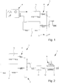
- Fig. 1 shows a drive system 1 with a main drive 2, a superposition gear 3 coupled to the main drive 2 and a control device 4.
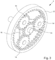
- Fig. 2 shows the use of the drive system 1 for a shredding device 7.
- the shredding device 7 is used to shred feed material 8, as shown schematically in FIG Fig. 2 is shown.
- household waste, biowaste, bulky waste, mixed construction waste, wood materials, in particular waste wood, trunk wood, root wood and / or green cuttings, and / or commercial waste can be provided as input material 8.
- the feed item 8 is a material that tends to be wound or contains material that has a tendency to be wound.
- Fig. 5 shows that the comminuting device 7 has a comminuting roller 9.
- Shredding tools 10, which are used to shred the feed material 8 can be arranged on the shredding roller 9.
- Fig. 6 shows that the comminuting tools 10 interact with counter-comminuting tools 11.
- the shredding roller 9 can be coupled to a roller shaft 12, in particular connected in a rotationally fixed manner.
- Fig. 2 it is shown that the drive system 1 is designed to drive the roller shaft 12.
- the main drive 2 serves to generate a rotary movement of the roller shaft 12 of the comminuting device 7.
- the control device 4 is designed to detect an overload of the shredding device 7. Furthermore, the control device 4 can be designed in such a way that it monitors the operating situation, preferably continuously, of the shredding device 7. An overload situation can occur when the feed material 8 becomes wedged between the shredding tools 10 and the counter-shredding tools 11. This can lead to the crushing roller 9 and thus the roller shaft 12 being blocked. In the event of an overload, the speed of the roller shaft 12 drops up to a blockage at 0 rpm.
- the main drive 2 Since the main drive 2 is still designed and used to drive the roller shaft 12 (ultimately to achieve a rotation of the roller shaft 12), high torques are applied to the main drive 2, which the torques of the normal operating situation - that is, during the regular, normal operation of the Crushing device 7 - sometimes considerably exceed.
- the torque on the electric motor 5 then increases, since the electric motor 5 is designed in particular to hold or hold the superposition branch 6 during the normal operating situation, so that the desired torque can be applied from the main drive 2 to the roller shaft 12.
- the in Fig. 1 The drive system 1 shown is provided that the control device 4 is designed in such a way that the electric motor 5 of the superposition branch 6 is controlled by the control device 4 in the event of an overload so that the superposition branch 6 of the superposition gear 3 causes a superposition movement in the superposition gear 3 so that the drive torque application of the main drive 2 to the roller shaft 12 can at least substantially be prevented or else reduced.
- a suppression of the drive torque application or transmission is to be understood in particular in such a way that ultimately the drive power application from the main drive 2 to the roller shaft 12 is at least substantially prevented or decoupled. Ultimately, the torque flow is compensated to "zero". Then the drive of the main drive 2 no longer leads to the drive of the roller shaft 12. The coupling between the main drive 2 and the roller shaft 12 can ultimately be prevented or compensated for by the superposition movement in the superposition gear 3. As a result, the high undesired torques on the main drive 2 can be avoided, since the main drive 2 can in particular continue to be driven without it having to be switched off or regulated down. Ultimately, the main drive 2 can continue to be operated as in normal operation.
- a related drive of the main drive 2 can be compensated for by the superposition movement which is caused by the superposition branch 6. This is ultimately necessary in the event of an overload when a blockage of the shredding roller 9 and thus the roller shaft 12 is to be expected, which is detected by the control device 4 and classified as an overload situation.
- the superposition movement caused in the superposition gear 3 by the superposition branch 6 leads to a speed of the roller shaft of 0 rpm, although the main drive 2 is driven.
- the overload case or the impending overload case is recognized as such by the control device 4 when the speed of the roller shaft is only less than 75%, preferably less than 50% and in particular less than 25% of the speed during normal operation. It is preferred if the speed at which the overload case is detected can be set by means of or in the control device 4.
- Fig. 2 shows that the drive train of the drive system 1, as viewed from the direction of the main drive 2 in the direction of the output, initially comprises the main drive 2, then the superposition gear 3 and then the roller shaft 12.
- the superposition branch 6 also acts on the superposition gear 3.
- the roller shaft 12 is ultimately the output shaft, the drive shaft being provided on the main drive 2 and the superimposition branch having a drive, output or standstill shaft.
- the torque is at least essentially completely transmitted from the main drive 2 to the roller shaft 12 - depending on the transmission ratio specified by the superimposed gear 3.
- the superposition branch 6 is designed to be stationary, with the electric motor 5 being able to act on the superposition branch 6 as and / or in combination with a separate brake.
- the coupling or the interaction between the control device 4 and the electric motor 5 of the superposition branch 6 is designed such that the control device 4 controls the electric motor 5 of the superposition branch 6 in the event of an overload so that the direction of rotation of the roller shaft 12 for a Reversing movement is reversed.
- a reversal of the direction of rotation of the roller shaft 12 is to be understood in particular in such a way that the direction of rotation originally specified by the main drive 2 is reversed in the normal operating situation of the shredding device 7.
- Such a reversal of the direction of rotation leads to the roller shaft 12 and thus the shredding roller 9 rotating in the opposite direction to the operating direction of rotation.
- the feed material 8 is wedged and / or trapped between the shredding tools 10 and the counter-shredding tools 11 or at another point in the shredding device 7, this can lead to the wedged feed material 8 becoming loosened. Accordingly, the possibility is opened up for the comminution device 7 to independently free itself from a blockage and / or jamming.
- control device 4 is designed such that the electric motor 5 of the superposition branch 6 is further controlled by the control device 4 to the effect that the speed, the torque and / or the power of the Main drive 2 can remain at least substantially constant during operation of the shredding device 7 and in particular in the event of an overload.
- At least essentially constant means a maximum deviation from the set control speed of a maximum of +/- 40%, preferably a maximum of +/- 30%.
- the speed, the torque and / or the power of the main drive 2 during the operation of the shredding device 7 and in particular in the event of an overload is within a tolerance range, in particular with +/- 10% fluctuation around the control value of the speed , the torque and / or the power is in the normal operating situation.
- the main drive 2 can be driven constantly with the same power and / or speed and, in particular, does not have to be switched off or regulated down in the event of an overload.
- the superposition gear 3 decouples the main drive 2 from the roller shaft 12, in particular in that the electric motor 5 acts against the main drive 2.
- the speed of the main drive 2 can be between 1000 and 3000 rpm, preferably between 1300 and 2000 rpm and in particular between 1500 and 1800 rpm.
- the control device 4 shown can thus be provided for controlling and / or regulating the operation of the shredding device 7, since it can ultimately determine the mode of operation of the electric motor 5 and thus of the superposition branch 6.
- the in Fig. 1 It is provided that the control device 4 is designed to monitor the torque of the electric motor 5 of the superposition branch 6 and / or to monitor the torque of the main drive 2.
- the control device 4 can also be designed to monitor the speed of the roller shaft 12 and / or the shredding roller 9. For this purpose, corresponding monitoring means are then provided, which are coupled to the control device 4.
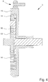
- Fig. 3 shows that the superposition gear 3 is a planetary superposition gear.
- the planetary superposition gear 3 comprises a sun gear 13, at least one planet gear 14 cooperating with the sun gear 13 and at least one ring gear 15 cooperating with the planet gear 14.
- a plurality of planet gears 14 is provided, which are connected to one another via a planet gear carrier 16.
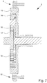
- Fig. 4 shows schematically the planetary superposition gear 3 in a cross-sectional view.
- the sun gear 13 is coupled to a shaft which in turn engages the main drive 2 (not shown).
- the main drive 2 consequently acts on the sun gear 13.
- the superposition branch 6 engages the ring gear 15 or includes it.
- the electric motor 5 is in turn connected to the superposition branch 6. In the exemplary embodiment shown, it is shown that the superposition branch 6 interacts with the ring gear 15.
- the ring gear 15 can thus also be viewed as a component of the superposition branch 6, which is provided for the task or superposition of a superposition movement in the superposition gear 3.
- the electric motor 5 can function as an additional drive unit.
- the roller shaft 12 can be connected to the planetary gear carrier 16, as in FIG Fig. 4 shown schematically, be connected.
- roller shaft 12 is engagingly connected to at least one planet gear 14.
- Fig. 3 shows that the planet gears 14 and the sun gear 13 are designed as gears which interact with one another by toothing or mesh with one another.
- the ring gear 15 has a toothing corresponding to the toothing of the planetary gears 14 in order to interact with the planetary gears 14.
- the planetary superposition gear 3 enables a high gear ratio with a small size.
- Fig. 2 The illustrated embodiment of the drive system 1 provides that a first gear stage with the superposition input and the additional auxiliary drive of the superposition branch 6 is provided.
- Fig. 2 further shows a further gear assembly 17, which can have a fixed but also an adjustable gear ratio with different gear stages.
- the further gear assembly 17 can be arranged on the planetary gear carrier 16 and / or on at least one planetary gear 14 and / or connected to it.
- the roller shaft 12 can in turn be arranged on the further gear assembly 17 and / or connected to it.
- a “connected” arrangement is to be understood as meaning that the respective assemblies ultimately interact with the respective drive shaft and are coupled to one another. These components can - but do not have to - be directly connected to one another.
- the in Fig. 1 The electric motor 5 shown is provided that the electric motor 5 of the superposition branch 6 is designed as a brake with, in particular, a variable braking effect.
- the electric motor 5 can be designed to hold and / or block the superimposition branch 6 during the regular operation of the shredding device 7, as well Fig. 4 shows.
- the electric motor 5 can ensure that no superimposed movement takes place in the superimposed gear 3 during normal operation of the comminuting device 7.
- the superposition branch 6 can for example comprise a gear which is coupled to the ring gear 15 for holding the ring gear 15 and / or for driving the ring gear 15.
- the superposition branch 6 can act on the ring gear 15 as a mechanical holding brake and force the ring gear 15 to come to a standstill during normal operation. In particular, no friction brake or the like is required. The braking effect can therefore take place exclusively through the electric motor 5.
- the electric motor 5 acting as a brake can bring about a speed adjustment of the roller shaft 12, in particular by reducing the braking effect.
- the superposition branch 6 acting as a brake can in particular functionally lengthen the axis of rotation of the electric motor 5 (also called the superposition motor) and / or be at least partially arranged as an extension of the axis of rotation of the electric motor 5.
- a brake of the superimposition branch 6, which is separate from the electric motor, can be closed by spring pressure in a de-energized and / or de-energized manner - based on a release element of the brake.
- a spring-loaded brake means that power operation can still be performed when the ring gear is at a standstill, even if the control system fails.
- the separate brake is only released when the electric motor 5 takes over the braking function or the supporting and counter torques at the same time.
- the control device 4 can be designed in such a way that, in the event of an overload, the electric motor 5 is activated in such a way that it interacts with the ring gear 15 so that the ring gear 15 can rotate.
- This movement of the ring gear 15 can be made possible and / or permitted by reducing the braking effect of the electric motor 5 on the ring gear 15.
- a rotation of the ring gear 15 for decoupling and / or reducing the application of drive torque from the sun gear 13 to the planetary gear carrier 16 is thus ensured and / or permitted.
- the speed of the ring gear 15 is increased by activating the control device 4 in such a way that the direction of rotation of the roller shaft 12 and in particular of the shredding roller 9 is reversed.
- the electric motor 5 can be coupled to the control device 4 in such a way that the reversing movement is only ensured for a certain time and / or a certain range (for example, measured by the angle of rotation, in particular of the roller shaft 12 or the shredding roller 9).
- Fig. 7 shows that an additional braking device 18 connected to the ring gear 15 is designed as a mechanical brake, preferably a friction brake.
- the additional braking device 18 can be provided in addition to the superposition branch 6.
- the mechanical brake can be designed in the manner described above in connection with the release element.
- the control device 4 shown can be designed such that, in the event of an overload, the maximum angle of rotation of the reversing movement of the roller shaft 12 of the reversing movement caused by the superposition branch 6 by the predetermined movement of the ring gear 15 is between 1 ° and 50 °. In further embodiments, the angle of rotation can be between 5 ° and 20 °. As a result, the shredding roller 9 can only rotate through the maximum angle of rotation, which is already sufficient to free wedged feed material 8 from the jamming.
- control device 4 can be designed in such a way that after a maximum of 10, preferably a maximum of 8, more preferably between 2 to 5, reversing movements of the roller shaft 12 within a maximum of 5 minutes - in further embodiments between 0.5 to 3 minutes - the shredding device 7 and / or the main drive 2 is switched off. This is done because it has been found in tests that after repeated back and forth movement of the shredding roller 9 in a predetermined time interval, wedged shredding material no longer loosens despite back and forth movement and manual intervention is then required in exceptional cases. What is not shown is that in this case an optical and / or acoustic warning signal is output via a signal device connected to the control device 4.
- the superposition gear 3 shown has a total gear ratio of 100 +/- 20. In further embodiments, the total gear ratio can be between 20 and 200.
- the shredding roller 9 shown and thus also the roller shaft 12 can have a speed of between 8 and 30 rpm during regular operation (control operation) of the shredding device 7. In further embodiments, the speed of the roller shaft 12 can be between 15 and 18 rpm.
- the in Fig. 1 The illustrated electric motor 5 of the superposition branch 6 can be designed as a synchronous motor.
- the in Fig. 4 The interaction shown between the superposition branch 6 and the ring gear 15 is provided in such a way that the main drive 2 can also be assisted by the electric motor 5, in particular to start the shredding device 7 Rotation for the required superposition movement in superposition gear 3 to prevent the drive torque application or the compensation of the torque flow to "zero" between sun gear 13 and planetary gear carrier 16. Accordingly, the electric motor 5 can be acted upon as an auxiliary drive unit in two different directions of rotation.
- the electric motor 5 can be designed as a starting control gear of the shredding device 7, which is advantageous for starting the main drive 2 under load.
- the electric motor 5 can therefore support the main drive 2.
- An electrical main drive 2 enables the use of an inexpensive asynchronous motor.
- the regulated - that is, with the roller shaft 12 at a standstill - load build-up from zero speed of the roller shaft 12 or the shredding roller 9 by the superposition gear 3 or by the superposition branch 6 is advantageous.
- the in Fig. 1 The electric motor 5 shown has a power between 30 and 200 kW. In other versions, the power can be between 60 and 100 kW.
- the in Fig. 2 The main drive 2 shown is provided that it is designed as an electric motor 5. It can have a power between 100 and 700 kW, in particular between 300 and 350 kW. It is not shown that the main drive 2 is designed as an internal combustion engine.
- a shredding device 7 is shown, which is provided for shredding input material 8, preferably household waste, biowaste, bulky waste, mixed construction waste, wood materials, in particular waste wood, trunk wood, root wood and / or green waste, and / or commercial waste.
- shredding input material 8 preferably household waste, biowaste, bulky waste, mixed construction waste, wood materials, in particular waste wood, trunk wood, root wood and / or green waste, and / or commercial waste.
- the shredding device 7 has at least one roller shaft 12, a shredding drum 9, preferably non-rotatably arranged on the drum shaft 12, with shredding tools 10 fastened therein, and a drive system 1 with the features of at least one of the embodiments described above.
- the shredding tools 10 cooperate with counter-shredding tools 11 for shredding the feed material 8, as shown schematically in FIG Fig. 6 is shown.
- the overload case occurs in particular if the feed material 8 has become wedged between the shredding tools 10 and the counter-shredding tools 11 or if the input material 8 winds up on or in the area of the shredding roller 9, which can block the shredding roller 9.
- Fig. 2 shows that the superposition gear 3 of the drive system 1 is arranged in the drive train between the main drive 2 and the roller shaft 12.
- the control device 4 is preferably designed in such a way that the speed of the shredding device 7, in particular the speed of the roller shaft 12, regulates itself, in particular as a function of the shredding power and / or as a function of the torque and / or the speed of the roller shaft 12 It is thus possible to react individually to different operating situations of the comminuting device 7.
Landscapes
- Engineering & Computer Science (AREA)
- Food Science & Technology (AREA)
- General Engineering & Computer Science (AREA)
- Mechanical Engineering (AREA)
- Crushing And Pulverization Processes (AREA)
Applications Claiming Priority (3)
| Application Number | Priority Date | Filing Date | Title |
|---|---|---|---|
| DE102020001729 | 2020-03-17 | ||
| DE102020001890 | 2020-03-24 | ||
| DE102020002135.2A DE102020002135A1 (de) | 2020-03-17 | 2020-04-03 | Verwendung eines Antriebssystems für eine Zerkleinerungsvorrichtung |
Publications (1)
| Publication Number | Publication Date |
|---|---|
| EP3909683A1 true EP3909683A1 (fr) | 2021-11-17 |
Family
ID=77552506
Family Applications (1)
| Application Number | Title | Priority Date | Filing Date |
|---|---|---|---|
| EP21162853.2A Withdrawn EP3909683A1 (fr) | 2020-03-17 | 2021-03-16 | Utilisation d'un système d'entraînement pour un dispositif de broyage |
Country Status (2)
| Country | Link |
|---|---|
| EP (1) | EP3909683A1 (fr) |
| DE (1) | DE102020002135A1 (fr) |
Cited By (1)
| Publication number | Priority date | Publication date | Assignee | Title |
|---|---|---|---|---|
| WO2023194091A1 (fr) * | 2022-04-07 | 2023-10-12 | Doppstadt Beteiligungs Gmbh | Dispositif de broyage servant à broyer un produit à broyer |
Citations (3)
| Publication number | Priority date | Publication date | Assignee | Title |
|---|---|---|---|---|
| DE3426083C1 (de) * | 1984-07-14 | 1985-10-17 | Zahnräderfabrik Renk AG, 8900 Augsburg | Antriebsvorrichtung für eine Schlagradmühle |
| WO1999025993A1 (fr) * | 1997-11-19 | 1999-05-27 | Abb Research Ltd. | Dispositif d'entrainement |
| DE202011103675U1 (de) * | 2011-07-26 | 2012-11-08 | Doppstadt Familienholding Gmbh | Zerkleinerungsvorrichtung |
-
2020
- 2020-04-03 DE DE102020002135.2A patent/DE102020002135A1/de active Pending
-
2021
- 2021-03-16 EP EP21162853.2A patent/EP3909683A1/fr not_active Withdrawn
Patent Citations (3)
| Publication number | Priority date | Publication date | Assignee | Title |
|---|---|---|---|---|
| DE3426083C1 (de) * | 1984-07-14 | 1985-10-17 | Zahnräderfabrik Renk AG, 8900 Augsburg | Antriebsvorrichtung für eine Schlagradmühle |
| WO1999025993A1 (fr) * | 1997-11-19 | 1999-05-27 | Abb Research Ltd. | Dispositif d'entrainement |
| DE202011103675U1 (de) * | 2011-07-26 | 2012-11-08 | Doppstadt Familienholding Gmbh | Zerkleinerungsvorrichtung |
Cited By (1)
| Publication number | Priority date | Publication date | Assignee | Title |
|---|---|---|---|---|
| WO2023194091A1 (fr) * | 2022-04-07 | 2023-10-12 | Doppstadt Beteiligungs Gmbh | Dispositif de broyage servant à broyer un produit à broyer |
Also Published As
| Publication number | Publication date |
|---|---|
| DE102020002135A1 (de) | 2021-09-23 |
Similar Documents
| Publication | Publication Date | Title |
|---|---|---|
| DE10333359B3 (de) | Zerkleinerungsvorrichtung für Abfälle | |
| DE102013114782B3 (de) | Zerkleinerungsvorrichtung mit einem Drehstrom-Asynchronmotor und einem kraftschlüssigen Zugmittelgetriebe sowie Verfahren zu dessen Betrieb | |
| EP1004234B1 (fr) | Dispositif pour la surveillance du module d'alimentation d'une machine agricole de récolte | |
| DE69706729T2 (de) | Wechselgetriebe | |
| DE3009106C2 (fr) | ||
| EP2711081A1 (fr) | Dispositif de broyage | |
| EP0313946B1 (fr) | Appareil déchiqueteur de documents | |
| EP2736646B1 (fr) | Dispositif de broyage | |
| EP3479674A1 (fr) | Moissonneuse agricole | |
| DE102007041878B4 (de) | Verfahren und Rollenmühle zur Zerkleinerung von Mahlgut | |
| EP3909683A1 (fr) | Utilisation d'un système d'entraînement pour un dispositif de broyage | |
| EP2699355A2 (fr) | Centrifugeuse et procédé pour contrôler un couple | |
| CH624021A5 (en) | Comminution machine | |
| EP0930941B1 (fr) | Procede et dispositif de surveillance automatique de machines, notamment de broyeurs, de preference, de lames de rotor | |
| DE2937846C2 (de) | Maschine zum Zerkleinern von sperrigem Material | |
| EP3981515B1 (fr) | Dispositif de broyage permettant de broyer un produit devant être broyé | |
| AT392221B (de) | Antriebsanordnung fuer zweirotorige prallbrecher | |
| DE4140549A1 (de) | Walzenmuehle | |
| EP2827020B1 (fr) | Engrenage pour un broyeur | |
| DE102008061734B4 (de) | Zerkleinerungsvorrichtung, insbesondere Trommelhacker | |
| DE102009038984B4 (de) | Vorrichtung zum Zerkleinern von Stückgut | |
| EP0532820B1 (fr) | Cisaille à tambour ou à levier | |
| EP3626348B1 (fr) | Dispositif de broyage des produits en vrac et procédé d'arrêt d'urgence du dispositif | |
| DE102012106915B4 (de) | Aktenvernichter | |
| DE20313327U1 (de) | Zerkleinerungsvorrichtung für Abfälle |
Legal Events
| Date | Code | Title | Description |
|---|---|---|---|
| PUAI | Public reference made under article 153(3) epc to a published international application that has entered the european phase |
Free format text: ORIGINAL CODE: 0009012 |
|
| STAA | Information on the status of an ep patent application or granted ep patent |
Free format text: STATUS: THE APPLICATION HAS BEEN PUBLISHED |
|
| AK | Designated contracting states |
Kind code of ref document: A1 Designated state(s): AL AT BE BG CH CY CZ DE DK EE ES FI FR GB GR HR HU IE IS IT LI LT LU LV MC MK MT NL NO PL PT RO RS SE SI SK SM TR |
|
| B565 | Issuance of search results under rule 164(2) epc |
Effective date: 20211018 |
|
| STAA | Information on the status of an ep patent application or granted ep patent |
Free format text: STATUS: REQUEST FOR EXAMINATION WAS MADE |
|
| 17P | Request for examination filed |
Effective date: 20220405 |
|
| RBV | Designated contracting states (corrected) |
Designated state(s): AL AT BE BG CH CY CZ DE DK EE ES FI FR GB GR HR HU IE IS IT LI LT LU LV MC MK MT NL NO PL PT RO RS SE SI SK SM TR |
|
| STAA | Information on the status of an ep patent application or granted ep patent |
Free format text: STATUS: EXAMINATION IS IN PROGRESS |
|
| 17Q | First examination report despatched |
Effective date: 20220630 |
|
| RAP1 | Party data changed (applicant data changed or rights of an application transferred) |
Owner name: DOPPSTADT BETEILIGUNGS GMBH |
|
| STAA | Information on the status of an ep patent application or granted ep patent |
Free format text: STATUS: THE APPLICATION HAS BEEN WITHDRAWN |
|
| 18W | Application withdrawn |
Effective date: 20250121 |