EP3909687B1 - Ensemble buse de détartrage amélioré - Google Patents
Ensemble buse de détartrage amélioré Download PDFInfo
- Publication number
- EP3909687B1 EP3909687B1 EP21173763.0A EP21173763A EP3909687B1 EP 3909687 B1 EP3909687 B1 EP 3909687B1 EP 21173763 A EP21173763 A EP 21173763A EP 3909687 B1 EP3909687 B1 EP 3909687B1
- Authority
- EP
- European Patent Office
- Prior art keywords
- vane
- upstream
- downstream
- liquid
- section
- Prior art date
- Legal status (The legal status is an assumption and is not a legal conclusion. Google has not performed a legal analysis and makes no representation as to the accuracy of the status listed.)
- Active
Links
Images


Classifications
-
- B—PERFORMING OPERATIONS; TRANSPORTING
- B05—SPRAYING OR ATOMISING IN GENERAL; APPLYING FLUENT MATERIALS TO SURFACES, IN GENERAL
- B05B—SPRAYING APPARATUS; ATOMISING APPARATUS; NOZZLES
- B05B1/00—Nozzles, spray heads or other outlets, with or without auxiliary devices such as valves, heating means
- B05B1/02—Nozzles, spray heads or other outlets, with or without auxiliary devices such as valves, heating means designed to produce a jet, spray, or other discharge of particular shape or nature, e.g. in single drops, or having an outlet of particular shape
- B05B1/10—Nozzles, spray heads or other outlets, with or without auxiliary devices such as valves, heating means designed to produce a jet, spray, or other discharge of particular shape or nature, e.g. in single drops, or having an outlet of particular shape in the form of a fine jet, e.g. for use in wind-screen washers
-
- B—PERFORMING OPERATIONS; TRANSPORTING
- B05—SPRAYING OR ATOMISING IN GENERAL; APPLYING FLUENT MATERIALS TO SURFACES, IN GENERAL
- B05B—SPRAYING APPARATUS; ATOMISING APPARATUS; NOZZLES
- B05B1/00—Nozzles, spray heads or other outlets, with or without auxiliary devices such as valves, heating means
- B05B1/34—Nozzles, spray heads or other outlets, with or without auxiliary devices such as valves, heating means designed to influence the nature of flow of the liquid or other fluent material, e.g. to produce swirl
- B05B1/3402—Nozzles, spray heads or other outlets, with or without auxiliary devices such as valves, heating means designed to influence the nature of flow of the liquid or other fluent material, e.g. to produce swirl to avoid or reduce turbulence, e.g. with fluid flow straightening means
-
- B—PERFORMING OPERATIONS; TRANSPORTING
- B05—SPRAYING OR ATOMISING IN GENERAL; APPLYING FLUENT MATERIALS TO SURFACES, IN GENERAL
- B05B—SPRAYING APPARATUS; ATOMISING APPARATUS; NOZZLES
- B05B1/00—Nozzles, spray heads or other outlets, with or without auxiliary devices such as valves, heating means
- B05B1/02—Nozzles, spray heads or other outlets, with or without auxiliary devices such as valves, heating means designed to produce a jet, spray, or other discharge of particular shape or nature, e.g. in single drops, or having an outlet of particular shape
- B05B1/04—Nozzles, spray heads or other outlets, with or without auxiliary devices such as valves, heating means designed to produce a jet, spray, or other discharge of particular shape or nature, e.g. in single drops, or having an outlet of particular shape in flat form, e.g. fan-like, sheet-like
- B05B1/048—Nozzles, spray heads or other outlets, with or without auxiliary devices such as valves, heating means designed to produce a jet, spray, or other discharge of particular shape or nature, e.g. in single drops, or having an outlet of particular shape in flat form, e.g. fan-like, sheet-like having a flow conduit with, immediately behind the outlet orifice, an elongated cross section, e.g. of oval or elliptic form, of which the major axis is perpendicular to the plane of the jet
-
- B—PERFORMING OPERATIONS; TRANSPORTING
- B05—SPRAYING OR ATOMISING IN GENERAL; APPLYING FLUENT MATERIALS TO SURFACES, IN GENERAL
- B05B—SPRAYING APPARATUS; ATOMISING APPARATUS; NOZZLES
- B05B1/00—Nozzles, spray heads or other outlets, with or without auxiliary devices such as valves, heating means
- B05B1/02—Nozzles, spray heads or other outlets, with or without auxiliary devices such as valves, heating means designed to produce a jet, spray, or other discharge of particular shape or nature, e.g. in single drops, or having an outlet of particular shape
- B05B1/04—Nozzles, spray heads or other outlets, with or without auxiliary devices such as valves, heating means designed to produce a jet, spray, or other discharge of particular shape or nature, e.g. in single drops, or having an outlet of particular shape in flat form, e.g. fan-like, sheet-like
-
- B—PERFORMING OPERATIONS; TRANSPORTING
- B08—CLEANING
- B08B—CLEANING IN GENERAL; PREVENTION OF FOULING IN GENERAL
- B08B3/00—Cleaning by methods involving the use or presence of liquid or steam
- B08B3/02—Cleaning by the force of jets or sprays
- B08B3/022—Cleaning travelling work
-
- B—PERFORMING OPERATIONS; TRANSPORTING
- B21—MECHANICAL METAL-WORKING WITHOUT ESSENTIALLY REMOVING MATERIAL; PUNCHING METAL
- B21B—ROLLING OF METAL
- B21B45/00—Devices for surface or other treatment of work, specially combined with or arranged in, or specially adapted for use in connection with, metal-rolling mills
- B21B45/04—Devices for surface or other treatment of work, specially combined with or arranged in, or specially adapted for use in connection with, metal-rolling mills for de-scaling, e.g. by brushing
- B21B45/08—Devices for surface or other treatment of work, specially combined with or arranged in, or specially adapted for use in connection with, metal-rolling mills for de-scaling, e.g. by brushing hydraulically
-
- B—PERFORMING OPERATIONS; TRANSPORTING
- B05—SPRAYING OR ATOMISING IN GENERAL; APPLYING FLUENT MATERIALS TO SURFACES, IN GENERAL
- B05B—SPRAYING APPARATUS; ATOMISING APPARATUS; NOZZLES
- B05B13/00—Machines or plants for applying liquids or other fluent materials to surfaces of objects or other work by spraying, not covered by groups B05B1/00 - B05B11/00
- B05B13/02—Means for supporting work; Arrangement or mounting of spray heads; Adaptation or arrangement of means for feeding work
- B05B13/0207—Means for supporting work; Arrangement or mounting of spray heads; Adaptation or arrangement of means for feeding work the work being an elongated body, e.g. wire or pipe
-
- B—PERFORMING OPERATIONS; TRANSPORTING
- B05—SPRAYING OR ATOMISING IN GENERAL; APPLYING FLUENT MATERIALS TO SURFACES, IN GENERAL
- B05B—SPRAYING APPARATUS; ATOMISING APPARATUS; NOZZLES
- B05B15/00—Details of spraying plant or spraying apparatus not otherwise provided for; Accessories
- B05B15/14—Arrangements for preventing or controlling structural damage to spraying apparatus or its outlets, e.g. for breaking at desired places; Arrangements for handling or replacing damaged parts
- B05B15/18—Arrangements for preventing or controlling structural damage to spraying apparatus or its outlets, e.g. for breaking at desired places; Arrangements for handling or replacing damaged parts for improving resistance to wear, e.g. inserts or coatings; for indicating wear; for handling or replacing worn parts
-
- B—PERFORMING OPERATIONS; TRANSPORTING
- B05—SPRAYING OR ATOMISING IN GENERAL; APPLYING FLUENT MATERIALS TO SURFACES, IN GENERAL
- B05B—SPRAYING APPARATUS; ATOMISING APPARATUS; NOZZLES
- B05B15/00—Details of spraying plant or spraying apparatus not otherwise provided for; Accessories
- B05B15/40—Filters located upstream of the spraying outlets
Definitions
- the present invention relates generally to spray nozzle assemblies, and more particularly, to descaling spray nozzle assemblies particularly effective for directing a wide thin-line high-pressure liquid discharge for penetrating and removing scale from steel in steel manufacturing operations.
- Descaling spray nozzle assemblies are extensively used in steel processing for directing a wide thin line high pressure spray onto the surface of steel slabs for penetrating and removing iron oxide scale buildup on the surfaces prior to rolling and subsequent processing of the steel.
- the high pressure liquid discharge be as thin as possible for effecting maximum impact pressure and penetration of the scale. It also is desirable that the distribution of the liquid discharge be uniform across the width of the spray pattern.
- Such descaling spray nozzle assemblies typically comprise a tubular body, sometimes referred to as a high impact attachment tube, formed with a liquid flow passageway that tapers inwardly in a downstream direction for accelerating the liquid flow, a strainer affixed to an upstream end of the tubular body for straining particulate matter and scale from recycled steel mill water typically used in such descaling processing, and a tungsten carbide insert tip mounted at downstream end of the tubular body having an elongated liquid discharge orifice for forming and directing a flat spray discharge pattern.
- High pressure liquid commonly at pressures of 13800-27800kPa (2000 to 4000 psi) directed through the strainer typically makes a right angle turn into the high impact attachment tube, creating extensive turbulence that can adversely affect the uniformity and impact force of the discharging spray.
- US 4848672 A describes a descaling nozzle having a straightening passage incorporating a straightener.
- GB 2459564 A describes a high-pressure liquid spray nozzle comprising an elongated tubular member defining a liquid passage having an inlet, a transversely oriented discharge outlet for emitting a flat liquid spray pattern, and a multi-stage vane section comprising upstream and downstream straightener vane sets located within the passage, each vane set having a plurality of circumferentially spaced vanes, the vanes of the downstream set being circumferentially offset from the vanes of the upstream set.
- Another object is to provide a descaling spray nozzle assembly as characterized above which has multiple staged liquid straightening vanes that more effectively reduce turbulence and energy losses of the liquid flow stream that can alter impact forces of the discharging liquid spray.
- a further object is to provide a descaling spray nozzle assembly of the foregoing type that has a plurality of liquid straightening vanes that is adapted for easier and more efficient assembly.
- a related object is to provide a descaling spray nozzle assembly of such type that eliminates the need for handling and precise assembly of a plurality of individual vanes.
- Yet a further object is to provide a descaling spray nozzle assembly of the foregoing type that is relative simple in design and lends itself to economical manufacture.
- an illustrative descaling spraying system 10 having a plurality of spray nozzle assemblies 11 in accordance with the invention for directing a high pressure liquid spray on opposed sides of a moving steel slab 12 in a steel manufacturing operation.
- the spraying system 10 in this case comprises upper and lower liquid supply headers 14a, 14b, typically supplied with mill water that is recycled in the steel manufacturing facility.
- These spray nozzle assemblies 11 are mounted in laterally-spaced relation along the respective header 14a, 14b such that a plurality of flat, thin-line spray patterns 13 penetrate and remove scale across the entire width of the steel slab 12.
- the spray nozzle assemblies 11 in this case are supported in depending fashion from the upper liquid supply header 14a for directing liquid spray onto an upper side of the moving slab 12 and spray nozzle assemblies 11 are supported in upwardly extending relation to the lower liquid supply header 14b for directing spray patterns across the underside of the slab 12.
- Each spray nozzle assembly 11 is supported by its respective header 14a, 14b with an upstream end within the header for receiving supply liquid from the header and a downstream end disposed outside the header in facing relation to the moving slab 12. Since each of the spray nozzle assemblies 11 are of similar construction, only one need be described herein in detail.
- the illustrated spray nozzle assemblies 11 each have an elongated nozzle body 13 comprising an upstream section in the form of an elongated generally cup-shaped liquid strainer 18 through which supply water from the header 14a, 14b enters the spray nozzle assembly 11 and a downstream section in the form of an elongated high impact attachment tube 15 supported within a wall 16 of the header 14a, 14b.
- a tungsten carbide insert spray tip 19 is mounted at a downstream end of the high impact attachment tube 15 formed with an elongated discharge orifice 20 for discharging and directing a flat spray pattern, and a spray tip retainer 21 secures the spray tip 19 in mounted position.
- the spray tip retainer 21 is threaded onto a downstream end of the high impact attachment tube 15 with an inwardly directed annular lip 22 retaining the spray tip 19 in abutting relation against a downstream end of the high impact attachment tube 15.
- the spray nozzle assembly 11 in this instance is supported within the header by means of a cylindrical adapter 23 appropriately fixed within a radial opening in the header 16.
- the adapter 23 has an externally threaded lower end against which an outwardly extending radial flange 21 a of the spray tip retainer 21 is retained by an internally threaded retaining ring 24 secured to the cylindrical adapter 23.
- the high impact attachment tube 15 is formed with a liquid flow passage 25 which tapers inwardly in a downstream direction.
- the tungsten carbide insert spray tip 19 affixed to the downstream end of high impact attachment tube 15 in this case is formed with an inlet passage section 32 that communicates between the high impact attachment tube passageway 25 and the discharge orifice 20 through a radiused entry passage section 34 ( FIG. 4 ).
- the elongated discharge orifice 20 in this instance is defined by a cylindrical groove or cut 35 extending transversely across the end of the spray tip 19 in intersecting relation with the entry passage section 34.
- the strainer 18 is formed with a plurality of elongated slits 38 circumferentially about the strainer communicating through a cylindrical sidewall 39 of the strainer and partially into the upstream end 39 a thereof.
- the supply water primarily enters the strainer 18 in a radial direction through the elongated slits 38 and must make a 90° change in directional movement, causing significant turbulence in the liquid, as it is directed toward the inwardly tapered passageway 25 of the high impact attachment tube 15 prior to direction from the spray tip 19.
- Turbulence in the high pressure liquid flow stream directed to the spray tip 19, as indicated above, can adversely affect the liquid discharge, particularly by increasing the transverse thickness of the thin line spray pattern, which reduces the liquid impact force and penetration, and thereby altering the liquid distribution, particularly at opposite ends of the wide spray pattern, which can result in uneven liquid penetration and scale removal.
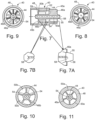
- the spray nozzle assembly has a one-piece multi-stage liquid straightening vane segment 40 disposed within a central liquid flow passage 41 of the nozzle body 13 defined by the upstream strainer 18 and the high impact attachment tube 15 that more effectively reduces liquid turbulence prior to direction to and through the spray tip 19, with resultant improved control in tightness of the thin, flat spray pattern and uniformity in liquid distribution throughout the spray pattern.
- the illustrated one-piece multi-stage liquid straightening vane segment 40 includes a plurality of integrally formed, and circumferentially offset liquid straightening vane sections 45a, 45b, which lends itself to easier and more efficient assembly and replacement in the spray nozzle assembly without cumbersome handling of a plurality of individual vane components.
- the illustrated one-piece vane segment 40 in this case comprises a central longitudinally extending hub 44 with a first or upstream vane section 45 a that includes a plurality of flat vane elements 46 a extending radially outwardly of the central hub 44 in radial planes through the longitudinal axis of the central liquid flow passage 41 and a second or downstream vane section 45 b downstream of the first vane section 45 a that includes a plurality of similar flat vane elements 46 b extending radially outwardly of the common central longitudinal hub 44 in circumferentially offset relation to the vane elements 45 a of the first vane section 45 a .
- the illustrated one-piece vane segment 40 has an outer cylindrical collar 48 integrally formed in surrounding relation to the vane elements 46 a, 46 b of both the upstream and downstream vane sections 46 a , 46 b .
- the outer collar 48, central hub 44, and the vane elements 46 a of the upstream vane section 45 a define a plurality of circumferentially spaced enclosed laminar flow passages 50 a , ( FIG. 11 ), and the outer collar 48, central hub 44 and vane elements 46 b of the downstream vane section 45 b define a second circumferential array of enclosed laminar flow passages 50 b circumferentially offset from the laminar passages 50 b of the first vane section 45 a ( FIG. 10 ).
- the vane sections 45 a , 45 b each have five radial vane elements 46 a , 46 b extending between the common central hub 44 and outer collar 48 for defining five circumferentially spaced laminar flow passages 50 a , 50 b , with the vane elements 46 b of the downstream vane section 45 b , as viewed in a longitudinal direction, being disposed midway between the vane elements 46 a of the upstream vane section 45 a .
- the vane sections 45 a , 45 b each have a common number of vane elements 46 a , 46 b between four and six
- the vane elements 46 b of the downstream vane section 46 b are axially spaced and circumferentially offset from the radial vane elements 46 a of the upstream vane section 45 a for providing a staged straightening of the high pressure liquid 46 a through the vane segment 40 prior to entering the high impact attachment tube 15.
- the vane elements 46 b of the downstream vane section 45 b are aligned in midway relation to the laminar flow passages 50 a of the upstream vane section 45 a .
- the vane elements 46 a , 46 b in this case each have an equal longitudinal length L and are separated by an axial gap D ( FIGS.
- the gap D is less than one half the axial length of the individual length of vane elements 46 a , 46 b .
- the vane segment 40 has a streamlined design for reducing turbulence and energy losses in the high pressure liquid flow stream directed through the vane segment 40. More particularly, the vane segment 40 is designed to minimize blunt surfaces that tend to impede and impart further turbulence to the high pressure liquid flow stream.
- the central hub 44 is formed with a longitudinal central passage 54 that defines a further laminar flow passageway through the vane segment 40.
- the central hub 44 further has a protrusion 55 extending upstream of the upstream valve section 45 a formed with a frustoconical outer liquid guide surface 56 ( FIGS. 7 and 7B ) that tapers radially outwardly in a downstream direction.
- the frustoconical liquid guide surface 56 in turn intersects the central liquid passage 54 of the hub 44 for defining a pointed annular entry end 58 both to the central liquid passage 54 and the frustoconical liquid guide surface 56. It has been found that such upstream protrusion 55 both facilitates direction of liquid into the central liquid passage 54 and onto the frustoconical liquid guide surface 56 and into laminar flow passages 50 a of the upstream valve section 45 a in a more controlled fashion without blunt surfaces that impart further turbulence to the high pressure liquid flow stream.
- the vane elements 46 a , 46 b of the upstream and downstream valve section 45 a , 45 b have upstream pointed end 58s, as depicted in FIG. 7A
- the central hub 44 in this case further has a downstream protrusion 59 with an outer frustoconical surface tapered inwardly in a downstream direction, again for guiding liquid from the laminar flow passages 46 b of the downstream valve section 45 b into the high pressure attachment tube 25.
- the spray nozzle assembly 11 is adapted for efficient assembly with the vane segment 40 comprising a discrete section of the nozzle body 13 of the spray nozzle assembly.
- the vane segment 40 is mounted in interposed relation between the upstream section of the nozzle body, namely the liquid strainer 18 in this case, and the downstream section of the nozzle body, namely the high impact attachment tube 15 in this case.
- a downstream end of the strainer 18 is fixedly crimped onto an upstream end of the vane segment collar 48, and the downstream end of the vane segment collar 48 is crimped onto the upstream end of high impact attachment tube 15.
- the collar 48 of the vane segment 40 in this case has a diameter coinciding with that of the high impact attachment tube 15 and strainer 18. It will be appreciated that such spray nozzle assembly 11 can be easily assembled without handling or precise alignment of multiplicity of liquid straightening vanes.
- a descaling spray nozzle assembly is provided for more effectively and efficiently straightening the liquid flow through the spray nozzle assembly with reduced turbulence and energy losses.
- the one-piece multi-staged liquid straightening vane segment further minimizes turbulence and energy losses of the liquid flow stream that can alter impact forces of the discharging liquid spray and is less susceptible to wear from high pressure liquid directed through the spray nozzle assembly after prolonged periods.
- the spray nozzle assembly furthermore, is adapted for easier and more efficient assembly and replacement without need for handling and precise alignment to a plurality of individual vane elements.
Landscapes
- Physics & Mathematics (AREA)
- Fluid Mechanics (AREA)
- Engineering & Computer Science (AREA)
- Mechanical Engineering (AREA)
- Nozzles (AREA)
Claims (15)
- Ensemble de buses de pulvérisation de liquide à fort impact (11) comprenant un corps de buse allongé (13) doté d'un passage de liquide (25) avec une section qui s'étend avec un diamètre effilé vers l'intérieur dans une direction aval le long d'un axe longitudinal du passage de liquide, un embout (19) au niveau d'une extrémité aval dudit corps de buse (13) doté d'un orifice de décharge allongé orienté transversalement à l'axe longitudinal du passage de liquide pour émettre et diriger un motif de pulvérisation plate de liquide (13), une entrée de liquide communiquant avec une extrémité dudit passage de liquide du corps de buse en amont dudit embout de pulvérisation, un segment d'aube monobloc à plusieurs étages (40) disposé dans ledit passage de liquide en amont dudit embout de pulvérisation, ledit segment d'aube monobloc comprenant une section d'aube amont de premier étage (45a) et une section d'aube aval de second étage (45b) en aval de ladite section d'aube amont de premier étage, lesdites sections d'aube amont de premier étage et d'aube aval de second étage ayant chacune une pluralité d'éléments d'aube plats (46a, 46b) définissant une pluralité de passages d'écoulement laminaire s'étendant longitudinalement espacés circonférentiellement communiquant entre ladite entrée de liquide et ledit embout de pulvérisation pour diriger le liquide longitudinalement dans une direction parallèle à l'axe longitudinal du passage de liquide, et lesdits éléments d'aube radiaux (46b) de ladite seconde section d'aube aval étant décalés circonférentiellement par rapport aux éléments d'aube radiaux (46a) de ladite première section d'aube amont.
- Ensemble de buses de pulvérisation selon la revendication 1, dans lequel ledit segment d'aube monobloc (40) comprend un moyeu central (44) s'étendant longitudinalement le long d'un centre du segment d'aube, et lesdits éléments d'aube desdites première section d'aube amont et seconde section d'aube aval s'étendent chacun radialement vers l'extérieur dudit moyeu central (44).
- Ensemble de buses de pulvérisation selon la revendication 2, dans lequel ledit segment d'aube monobloc (40) comporte un collier cylindrique externe formé d'un seul tenant (48) disposé dans un rapport entourant les éléments d'aube desdites première section d'aube amont et seconde section d'aube aval de sorte que le moyeu central (44), les éléments d'aube (46a, 46b) et le collier cylindrique externe (48) enferment circonférentiellement ladite pluralité de passages d'écoulement laminaire qui s'étendent axialement à travers les sections d'aube.
- Ensemble de buses de pulvérisation selon la revendication 2, dans lequel ledit moyeu central (44) dudit segment d'aube monobloc présente une saillie amont (55) s'étendant en amont de ladite première section d'aube amont, ladite saillie amont (55) ayant une surface de guidage externe tronconique (56) effilée vers l'extérieur dans une direction aval pour guider du liquide dans lesdits passages d'écoulement laminaire espacés circonférentiellement de ladite première section d'aube amont.
- Ensemble de buses de pulvérisation selon la revendication 4, dans lequel ledit moyeu central (44) présente un passage axial s'étendant à travers le moyeu (44) pour définir un autre passage d'écoulement laminaire, et ladite surface de guidage tronconique (56) de ladite saillie de moyeu amont coupe le passage axial dudit moyeu pour former une extrémité amont annulaire pointue (58) de la saillie amont (55) pour diviser le flux de liquide afin de le diriger à travers ledit passage laminaire du moyeu central et sur ladite surface de guidage tronconique de ladite saillie amont.
- Ensemble de buses de pulvérisation selon la revendication 4, dans lequel lesdits éléments d'aube des première section d'aube amont et seconde section d'aube aval présentent des extrémités pointues en amont (58) pour diviser l'écoulement de liquide en passages d'écoulement laminaire circonférentiels respectifs de la section d'aube respective.
- Ensemble de buses de pulvérisation selon la revendication 4, dans lequel ledit moyeu central (44) présente une saillie tronconique aval (59) effilée vers l'intérieur dans la direction aval pour guider du liquide depuis lesdits passages d'écoulement laminaire espacés circonférentiellement de ladite seconde section d'aube aval.
- Ensemble de buses de pulvérisation selon la revendication 2, dans lequel soit1) lesdites sections d'aube présentent chacune un nombre similaire d'éléments d'aube, ou2) les éléments d'aube (46a, 46b) desdites première section d'aube amont et seconde section d'aube aval sont décalés circonférentiellement les uns par rapport aux autres de sorte que les éléments d'aube radiaux de ladite seconde section d'aube aval (45b) sont orientés dans un rapport sensiblement centré sur des paires d'éléments d'aube radiaux de la première section d'aube amont (45a), vus dans une direction axiale de celle-ci, ou3) lesdites sections d'aube sont disposées dans un rapport de distance axiale les unes des autres de manière à définir un passage de transition entre lesdites sections d'aube.
- Ensemble de buses de pulvérisation selon la revendication 1, dans lequel ladite entrée de liquide est définie par une crépine (18) formée avec une pluralité d'ouvertures longitudinales disposées circonférentiellement autour de la crépine dans un rapport parallèle à un axe longitudinal dudit corps de buse allongé.
- Ensemble de buses de pulvérisation selon la revendication 1, dans lequel ledit corps de buse allongé (13) comporte une section de corps en amont dotée de l'entrée de liquide et une section de corps en aval comportant un tube de fixation à fort impact (15) doté de la section du passage de liquide qui s'étend avec un diamètre effilé vers l'intérieur dans une direction aval le long d'un axe longitudinal du passage de liquide, ledit segment d'aube monobloc à plusieurs étages (40) étant interposé entre lesdites sections de corps amont et aval.
- Ensemble de buses de pulvérisation selon la revendication 10, dans lequel ledit segment d'aube monobloc à plusieurs étages (40) est relié dans un rapport interposé entre lesdites sections de corps amont et aval.
- Ensemble de buses de pulvérisation selon la revendication 10, dans lequel ledit segment d'aube monobloc à plusieurs étages (40) présente un collier cylindrique externe intégré (48) aux éléments d'aube desdites première section d'aube amont et seconde section d'aube aval (46a, 46b), et ledit collier cylindrique extérieur (48) présente une extrémité amont fixée à ladite section de corps amont et une extrémité aval fixée à ladite section de corps aval.
- Ensemble de buses de pulvérisation selon la revendication 12, dans lequel ledit segment d'aube monobloc à plusieurs étages (40) comporte un moyeu central (44) s'étendant longitudinalement le long d'un axe central de celui-ci, et lesdits éléments d'aube desdites première section d'aube amont et seconde section d'aube aval s'étendent chacun radialement vers l'extérieur dudit moyeu central (44).
- Ensemble de buses de pulvérisation selon la revendication 13, dans lequel ledit collier cylindrique externe (48) est disposé dans un rapport entourant les éléments d'aube desdites première section d'aube amont et seconde section d'aube aval de sorte que le moyeu central, les éléments d'aube et le collier cylindrique externe (48) enferment circonférentiellement ladite pluralité de passages d'écoulement laminaire qui s'étendent axialement à travers les sections d'aube et dans lequel éventuellement1) ledit moyeu central (44) présente un passage axial (54) s'étendant à travers le moyeu pour définir un autre passage d'écoulement laminaire, ou2) ledit moyeu central (44) dudit segment d'aube monobloc à plusieurs étages (40) présente une saillie amont (55) s'étendant en amont de ladite première section d'aube amont, ladite saillie amont (55) ayant une surface de guidage externe tronconique (56) effilée vers l'extérieur dans une direction aval pour guider le liquide dans lesdits passages d'écoulement laminaire espacés circonférentiellement de ladite première section d'aube amont (45a) .
- Ensemble de buses de pulvérisation selon la revendication 14, option 2), dans lequel ledit moyeu central (44) présente un passage axial (54) s'étendant à travers le moyeu pour définir un autre passage d'écoulement laminaire, et ladite surface de guidage tronconique (56) de ladite saillie de moyeu amont coupe le passage axial dudit moyeu pour former une extrémité amont annulaire pointue (58) de la saillie amont pour diviser l'écoulement de liquide afin de le diriger à travers ledit passage laminaire du moyeu central et sur ladite surface de guidage tronconique de ladite saillie amont et éventuellement lesdits éléments d'aube des première section d'aube amont et seconde section d'aube aval présentent des extrémités pointues amont (58) pour diviser l'écoulement de liquide en passages d'écoulement laminaire circonférentiels respectifs de la section d'aube respective.
Applications Claiming Priority (1)
| Application Number | Priority Date | Filing Date | Title |
|---|---|---|---|
| US202063025760P | 2020-05-15 | 2020-05-15 |
Publications (3)
| Publication Number | Publication Date |
|---|---|
| EP3909687A1 EP3909687A1 (fr) | 2021-11-17 |
| EP3909687B1 true EP3909687B1 (fr) | 2024-01-10 |
| EP3909687C0 EP3909687C0 (fr) | 2024-01-10 |
Family
ID=76269564
Family Applications (1)
| Application Number | Title | Priority Date | Filing Date |
|---|---|---|---|
| EP21173763.0A Active EP3909687B1 (fr) | 2020-05-15 | 2021-05-13 | Ensemble buse de détartrage amélioré |
Country Status (5)
| Country | Link |
|---|---|
| US (1) | US20210354149A1 (fr) |
| EP (1) | EP3909687B1 (fr) |
| JP (1) | JP7752961B2 (fr) |
| CN (1) | CN113663825A (fr) |
| BR (1) | BR102021009461A2 (fr) |
Families Citing this family (4)
| Publication number | Priority date | Publication date | Assignee | Title |
|---|---|---|---|---|
| EP3914630A1 (fr) * | 2019-01-24 | 2021-12-01 | Lummus Novolen Technology Gmbh | Tuyau de pulvérisation centré |
| AR126402A1 (es) * | 2021-11-24 | 2023-10-11 | Pmi South America Consumer Goods Ltda | Dispositivo de control de flujo para inserción en aberturas de recipientes |
| CN116274438B (zh) * | 2023-01-18 | 2025-12-12 | 辽宁科技大学 | 一种除鳞喷头及除鳞喷嘴 |
| CN117182050A (zh) * | 2023-09-07 | 2023-12-08 | 安徽绿能技术研究院有限公司 | 一种铜杆铸胚冷却设备及其制备方法 |
Family Cites Families (25)
| Publication number | Priority date | Publication date | Assignee | Title |
|---|---|---|---|---|
| US2054964A (en) * | 1935-12-06 | 1936-09-22 | Horace R Barker | Fluid discharge device |
| US2844408A (en) * | 1956-02-25 | 1958-07-22 | Waldemar Foerstner | Nozzles |
| US3510065A (en) * | 1968-01-05 | 1970-05-05 | Steinen Mfg Co Wm | Descaling nozzle |
| US4365758A (en) * | 1981-04-28 | 1982-12-28 | Schaming Edward J | Descaling nozzle |
| GB2105220B (en) * | 1981-09-07 | 1985-07-17 | Butterworth System Inc | A stream straightener for a nozzle |
| US4617815A (en) * | 1984-12-24 | 1986-10-21 | Wean United, Inc. | Apparatus for descaling hot strip in a rolling mill |
| JPH0673697B2 (ja) * | 1987-10-24 | 1994-09-21 | 株式会社共立合金製作所 | スケール除去用ノズル |
| US4875627A (en) * | 1988-07-08 | 1989-10-24 | Lechler, Inc. | Free passage nozzle |
| US5158235A (en) * | 1991-02-19 | 1992-10-27 | Elwood Hydraulics Company, Inc. | Turbulence-quelling fluid-flow controller and method |
| US5460023A (en) * | 1991-09-13 | 1995-10-24 | International Rolling Mill Consultants Inc. | Roll surface restoration system and method |
| US5675880A (en) * | 1996-08-29 | 1997-10-14 | Bethlehem Steel Corporation | Descaling system for use in the manufacture of steel and corresponding method |
| US6561440B1 (en) * | 2001-11-14 | 2003-05-13 | Spraying Systems Co. | Full cone spray nozzle for metal casting cooling system |
| KR100606629B1 (ko) * | 2002-12-25 | 2006-07-31 | 가부시키가이샤 교리쯔 고우낀 세이사꾸쇼 | 디스케일링 노즐 및 초경합금 노즐팁 |
| US20050072866A1 (en) * | 2003-10-01 | 2005-04-07 | Petit Kevin J. | Turbulent flow reducer |
| US9919171B2 (en) * | 2007-07-12 | 2018-03-20 | Watershield Llc | Fluid control device and method for projecting a fluid |
| WO2009039477A1 (fr) * | 2007-09-21 | 2009-03-26 | Parker-Hannifin Corporation | Mélangeur statique compact et procédé de mélange associé |
| JP2009101411A (ja) * | 2007-10-02 | 2009-05-14 | Kyoritsu Gokin Co Ltd | デスケーリングノズル |
| US7913937B2 (en) * | 2008-05-02 | 2011-03-29 | Spraying Systems Co. | Descaling spray nozzle assembly |
| JP2010221257A (ja) * | 2009-03-24 | 2010-10-07 | Kyoritsu Gokin Co Ltd | スプレーノズルとそのフィルター構造 |
| JP2011115749A (ja) * | 2009-12-07 | 2011-06-16 | Kyoritsu Gokin Co Ltd | 整流部材及びそれを備えたノズル |
| JP5834852B2 (ja) * | 2010-12-14 | 2015-12-24 | Jfeスチール株式会社 | 鋼板のスケール除去用ノズルおよび鋼板のスケール除去装置並びに鋼板のスケール除去方法 |
| DE102011076443B4 (de) * | 2011-05-25 | 2013-01-17 | Lechler Gmbh | Rückschlagventil für Sprühdüse und Düsenrohr |
| US10518117B2 (en) * | 2015-10-12 | 2019-12-31 | Task Force Tips Llc | Firefighting nozzle |
| CN106139484A (zh) * | 2016-08-12 | 2016-11-23 | 福建天广消防有限公司 | 一种出水整流装置及水炮炮头 |
| DE102016221729A1 (de) * | 2016-11-07 | 2018-05-09 | Lechler Gmbh | Filter-Strahlrichtereinheit und Hochdruckdüseneinheit |
-
2021
- 2021-05-13 EP EP21173763.0A patent/EP3909687B1/fr active Active
- 2021-05-13 JP JP2021081830A patent/JP7752961B2/ja active Active
- 2021-05-14 US US17/320,695 patent/US20210354149A1/en active Pending
- 2021-05-14 CN CN202110526927.9A patent/CN113663825A/zh active Pending
- 2021-05-14 BR BR102021009461-3A patent/BR102021009461A2/pt unknown
Also Published As
| Publication number | Publication date |
|---|---|
| JP7752961B2 (ja) | 2025-10-14 |
| JP2021178319A (ja) | 2021-11-18 |
| BR102021009461A2 (pt) | 2021-11-16 |
| CN113663825A (zh) | 2021-11-19 |
| EP3909687A1 (fr) | 2021-11-17 |
| US20210354149A1 (en) | 2021-11-18 |
| EP3909687C0 (fr) | 2024-01-10 |
Similar Documents
| Publication | Publication Date | Title |
|---|---|---|
| EP3909687B1 (fr) | Ensemble buse de détartrage amélioré | |
| US7913937B2 (en) | Descaling spray nozzle assembly | |
| EP1596989B1 (fr) | Ensemble buse de pulverisation assiste par de l'air permettant de pulveriser des liquides visqueux | |
| EP1444047B1 (fr) | Buse de pulverisation de liquide en cône plein | |
| EP2739400B1 (fr) | Ensemble buse de pulvérisation assistée par air sous pression | |
| US7611080B2 (en) | Full cone air assisted spray nozzle for continuous metal casting cooling | |
| EP1575719B2 (fr) | Buse de detartrage | |
| EP1160015A2 (fr) | Buse de pulvérisation pneumatique | |
| CA2332096A1 (fr) | Buse de vaporisateur avec chapeau ameliore | |
| US6851632B2 (en) | High-pressure cleaning spray nozzle | |
| US8590816B2 (en) | Spray nozzle for liquid and device for spraying liquid comprising such a nozzle | |
| CN105212802A (zh) | 具有改进的内部冷却剂递送的刀架 | |
| EP2744598B1 (fr) | Ensemble de buses de pulvérisation à induction d'air et à évacuations multiples | |
| AU538248B2 (en) | Blowing nozzle | |
| AU6578880A (en) | Blowing nozzle | |
| EP3915685B1 (fr) | Buse | |
| US10195619B2 (en) | Catalytic cracking spray nozzle assembly with liquid inlet extension and diffuser | |
| SU1101326A1 (ru) | Форсунка дл водовоздушного охлаждени непрерывнолитых заготовок пр моугольного сечени |
Legal Events
| Date | Code | Title | Description |
|---|---|---|---|
| PUAI | Public reference made under article 153(3) epc to a published international application that has entered the european phase |
Free format text: ORIGINAL CODE: 0009012 |
|
| STAA | Information on the status of an ep patent application or granted ep patent |
Free format text: STATUS: THE APPLICATION HAS BEEN PUBLISHED |
|
| AK | Designated contracting states |
Kind code of ref document: A1 Designated state(s): AL AT BE BG CH CY CZ DE DK EE ES FI FR GB GR HR HU IE IS IT LI LT LU LV MC MK MT NL NO PL PT RO RS SE SI SK SM TR |
|
| B565 | Issuance of search results under rule 164(2) epc |
Effective date: 20211008 |
|
| STAA | Information on the status of an ep patent application or granted ep patent |
Free format text: STATUS: REQUEST FOR EXAMINATION WAS MADE |
|
| RIC1 | Information provided on ipc code assigned before grant |
Ipc: B05B 1/00 20060101AFI20220314BHEP |
|
| 17P | Request for examination filed |
Effective date: 20220413 |
|
| RBV | Designated contracting states (corrected) |
Designated state(s): AL AT BE BG CH CY CZ DE DK EE ES FI FR GB GR HR HU IE IS IT LI LT LU LV MC MK MT NL NO PL PT RO RS SE SI SK SM TR |
|
| GRAP | Despatch of communication of intention to grant a patent |
Free format text: ORIGINAL CODE: EPIDOSNIGR1 |
|
| STAA | Information on the status of an ep patent application or granted ep patent |
Free format text: STATUS: GRANT OF PATENT IS INTENDED |
|
| INTG | Intention to grant announced |
Effective date: 20230718 |
|
| GRAS | Grant fee paid |
Free format text: ORIGINAL CODE: EPIDOSNIGR3 |
|
| GRAA | (expected) grant |
Free format text: ORIGINAL CODE: 0009210 |
|
| STAA | Information on the status of an ep patent application or granted ep patent |
Free format text: STATUS: THE PATENT HAS BEEN GRANTED |
|
| AK | Designated contracting states |
Kind code of ref document: B1 Designated state(s): AL AT BE BG CH CY CZ DE DK EE ES FI FR GB GR HR HU IE IS IT LI LT LU LV MC MK MT NL NO PL PT RO RS SE SI SK SM TR |
|
| REG | Reference to a national code |
Ref country code: GB Ref legal event code: FG4D |
|
| REG | Reference to a national code |
Ref country code: CH Ref legal event code: EP |
|
| REG | Reference to a national code |
Ref country code: DE Ref legal event code: R096 Ref document number: 602021008442 Country of ref document: DE |
|
| REG | Reference to a national code |
Ref country code: IE Ref legal event code: FG4D |
|
| U01 | Request for unitary effect filed |
Effective date: 20240130 |
|
| U07 | Unitary effect registered |
Designated state(s): AT BE BG DE DK EE FI FR IT LT LU LV MT NL PT SE SI Effective date: 20240208 |
|
| U20 | Renewal fee for the european patent with unitary effect paid |
Year of fee payment: 4 Effective date: 20240408 |
|
| PG25 | Lapsed in a contracting state [announced via postgrant information from national office to epo] |
Ref country code: IS Free format text: LAPSE BECAUSE OF FAILURE TO SUBMIT A TRANSLATION OF THE DESCRIPTION OR TO PAY THE FEE WITHIN THE PRESCRIBED TIME-LIMIT Effective date: 20240510 |
|
| PG25 | Lapsed in a contracting state [announced via postgrant information from national office to epo] |
Ref country code: GR Free format text: LAPSE BECAUSE OF FAILURE TO SUBMIT A TRANSLATION OF THE DESCRIPTION OR TO PAY THE FEE WITHIN THE PRESCRIBED TIME-LIMIT Effective date: 20240411 |
|
| PG25 | Lapsed in a contracting state [announced via postgrant information from national office to epo] |
Ref country code: HR Free format text: LAPSE BECAUSE OF FAILURE TO SUBMIT A TRANSLATION OF THE DESCRIPTION OR TO PAY THE FEE WITHIN THE PRESCRIBED TIME-LIMIT Effective date: 20240110 Ref country code: RS Free format text: LAPSE BECAUSE OF FAILURE TO SUBMIT A TRANSLATION OF THE DESCRIPTION OR TO PAY THE FEE WITHIN THE PRESCRIBED TIME-LIMIT Effective date: 20240410 |
|
| PG25 | Lapsed in a contracting state [announced via postgrant information from national office to epo] |
Ref country code: ES Free format text: LAPSE BECAUSE OF FAILURE TO SUBMIT A TRANSLATION OF THE DESCRIPTION OR TO PAY THE FEE WITHIN THE PRESCRIBED TIME-LIMIT Effective date: 20240110 |
|
| PG25 | Lapsed in a contracting state [announced via postgrant information from national office to epo] |
Ref country code: RS Free format text: LAPSE BECAUSE OF FAILURE TO SUBMIT A TRANSLATION OF THE DESCRIPTION OR TO PAY THE FEE WITHIN THE PRESCRIBED TIME-LIMIT Effective date: 20240410 Ref country code: NO Free format text: LAPSE BECAUSE OF FAILURE TO SUBMIT A TRANSLATION OF THE DESCRIPTION OR TO PAY THE FEE WITHIN THE PRESCRIBED TIME-LIMIT Effective date: 20240410 Ref country code: IS Free format text: LAPSE BECAUSE OF FAILURE TO SUBMIT A TRANSLATION OF THE DESCRIPTION OR TO PAY THE FEE WITHIN THE PRESCRIBED TIME-LIMIT Effective date: 20240510 Ref country code: HR Free format text: LAPSE BECAUSE OF FAILURE TO SUBMIT A TRANSLATION OF THE DESCRIPTION OR TO PAY THE FEE WITHIN THE PRESCRIBED TIME-LIMIT Effective date: 20240110 Ref country code: GR Free format text: LAPSE BECAUSE OF FAILURE TO SUBMIT A TRANSLATION OF THE DESCRIPTION OR TO PAY THE FEE WITHIN THE PRESCRIBED TIME-LIMIT Effective date: 20240411 Ref country code: ES Free format text: LAPSE BECAUSE OF FAILURE TO SUBMIT A TRANSLATION OF THE DESCRIPTION OR TO PAY THE FEE WITHIN THE PRESCRIBED TIME-LIMIT Effective date: 20240110 |
|
| PG25 | Lapsed in a contracting state [announced via postgrant information from national office to epo] |
Ref country code: PL Free format text: LAPSE BECAUSE OF FAILURE TO SUBMIT A TRANSLATION OF THE DESCRIPTION OR TO PAY THE FEE WITHIN THE PRESCRIBED TIME-LIMIT Effective date: 20240110 |
|
| PG25 | Lapsed in a contracting state [announced via postgrant information from national office to epo] |
Ref country code: PL Free format text: LAPSE BECAUSE OF FAILURE TO SUBMIT A TRANSLATION OF THE DESCRIPTION OR TO PAY THE FEE WITHIN THE PRESCRIBED TIME-LIMIT Effective date: 20240110 |
|
| REG | Reference to a national code |
Ref country code: DE Ref legal event code: R097 Ref document number: 602021008442 Country of ref document: DE |
|
| PG25 | Lapsed in a contracting state [announced via postgrant information from national office to epo] |
Ref country code: SM Free format text: LAPSE BECAUSE OF FAILURE TO SUBMIT A TRANSLATION OF THE DESCRIPTION OR TO PAY THE FEE WITHIN THE PRESCRIBED TIME-LIMIT Effective date: 20240110 |
|
| PG25 | Lapsed in a contracting state [announced via postgrant information from national office to epo] |
Ref country code: CZ Free format text: LAPSE BECAUSE OF FAILURE TO SUBMIT A TRANSLATION OF THE DESCRIPTION OR TO PAY THE FEE WITHIN THE PRESCRIBED TIME-LIMIT Effective date: 20240110 |
|
| PG25 | Lapsed in a contracting state [announced via postgrant information from national office to epo] |
Ref country code: SK Free format text: LAPSE BECAUSE OF FAILURE TO SUBMIT A TRANSLATION OF THE DESCRIPTION OR TO PAY THE FEE WITHIN THE PRESCRIBED TIME-LIMIT Effective date: 20240110 |
|
| PG25 | Lapsed in a contracting state [announced via postgrant information from national office to epo] |
Ref country code: SM Free format text: LAPSE BECAUSE OF FAILURE TO SUBMIT A TRANSLATION OF THE DESCRIPTION OR TO PAY THE FEE WITHIN THE PRESCRIBED TIME-LIMIT Effective date: 20240110 Ref country code: SK Free format text: LAPSE BECAUSE OF FAILURE TO SUBMIT A TRANSLATION OF THE DESCRIPTION OR TO PAY THE FEE WITHIN THE PRESCRIBED TIME-LIMIT Effective date: 20240110 Ref country code: RO Free format text: LAPSE BECAUSE OF FAILURE TO SUBMIT A TRANSLATION OF THE DESCRIPTION OR TO PAY THE FEE WITHIN THE PRESCRIBED TIME-LIMIT Effective date: 20240110 Ref country code: CZ Free format text: LAPSE BECAUSE OF FAILURE TO SUBMIT A TRANSLATION OF THE DESCRIPTION OR TO PAY THE FEE WITHIN THE PRESCRIBED TIME-LIMIT Effective date: 20240110 |
|
| PLBE | No opposition filed within time limit |
Free format text: ORIGINAL CODE: 0009261 |
|
| STAA | Information on the status of an ep patent application or granted ep patent |
Free format text: STATUS: NO OPPOSITION FILED WITHIN TIME LIMIT |
|
| 26N | No opposition filed |
Effective date: 20241011 |
|
| REG | Reference to a national code |
Ref country code: CH Ref legal event code: PL |
|
| PG25 | Lapsed in a contracting state [announced via postgrant information from national office to epo] |
Ref country code: MC Free format text: LAPSE BECAUSE OF FAILURE TO SUBMIT A TRANSLATION OF THE DESCRIPTION OR TO PAY THE FEE WITHIN THE PRESCRIBED TIME-LIMIT Effective date: 20240110 |
|
| PG25 | Lapsed in a contracting state [announced via postgrant information from national office to epo] |
Ref country code: MC Free format text: LAPSE BECAUSE OF FAILURE TO SUBMIT A TRANSLATION OF THE DESCRIPTION OR TO PAY THE FEE WITHIN THE PRESCRIBED TIME-LIMIT Effective date: 20240110 Ref country code: CH Free format text: LAPSE BECAUSE OF NON-PAYMENT OF DUE FEES Effective date: 20240531 |
|
| PG25 | Lapsed in a contracting state [announced via postgrant information from national office to epo] |
Ref country code: IE Free format text: LAPSE BECAUSE OF NON-PAYMENT OF DUE FEES Effective date: 20240513 |
|
| U20 | Renewal fee for the european patent with unitary effect paid |
Year of fee payment: 5 Effective date: 20250407 |
|
| PG25 | Lapsed in a contracting state [announced via postgrant information from national office to epo] |
Ref country code: CY Free format text: LAPSE BECAUSE OF FAILURE TO SUBMIT A TRANSLATION OF THE DESCRIPTION OR TO PAY THE FEE WITHIN THE PRESCRIBED TIME-LIMIT; INVALID AB INITIO Effective date: 20210513 |
|
| PG25 | Lapsed in a contracting state [announced via postgrant information from national office to epo] |
Ref country code: HU Free format text: LAPSE BECAUSE OF FAILURE TO SUBMIT A TRANSLATION OF THE DESCRIPTION OR TO PAY THE FEE WITHIN THE PRESCRIBED TIME-LIMIT; INVALID AB INITIO Effective date: 20210513 |
|
| GBPC | Gb: european patent ceased through non-payment of renewal fee |
Effective date: 20250513 |
|
| PG25 | Lapsed in a contracting state [announced via postgrant information from national office to epo] |
Ref country code: GB Free format text: LAPSE BECAUSE OF NON-PAYMENT OF DUE FEES Effective date: 20250513 |