EP3909694A1 - Procédé de lavage d'un séparateur pour le traitement d'urée fondue et équipement de séparation associé - Google Patents
Procédé de lavage d'un séparateur pour le traitement d'urée fondue et équipement de séparation associé Download PDFInfo
- Publication number
- EP3909694A1 EP3909694A1 EP21173729.1A EP21173729A EP3909694A1 EP 3909694 A1 EP3909694 A1 EP 3909694A1 EP 21173729 A EP21173729 A EP 21173729A EP 3909694 A1 EP3909694 A1 EP 3909694A1
- Authority
- EP
- European Patent Office
- Prior art keywords
- separator
- urea
- side wall
- openings
- distributor element
- Prior art date
- Legal status (The legal status is an assumption and is not a legal conclusion. Google has not performed a legal analysis and makes no representation as to the accuracy of the status listed.)
- Granted
Links
Images



Classifications
-
- B—PERFORMING OPERATIONS; TRANSPORTING
- B08—CLEANING
- B08B—CLEANING IN GENERAL; PREVENTION OF FOULING IN GENERAL
- B08B9/00—Cleaning hollow articles by methods or apparatus specially adapted thereto
- B08B9/08—Cleaning containers, e.g. tanks
- B08B9/0804—Cleaning containers having tubular shape, e.g. casks, barrels, drums
- B08B9/0813—Cleaning containers having tubular shape, e.g. casks, barrels, drums by the force of jets or sprays
-
- B—PERFORMING OPERATIONS; TRANSPORTING
- B01—PHYSICAL OR CHEMICAL PROCESSES OR APPARATUS IN GENERAL
- B01J—CHEMICAL OR PHYSICAL PROCESSES, e.g. CATALYSIS OR COLLOID CHEMISTRY; THEIR RELEVANT APPARATUS
- B01J3/00—Processes of utilising sub-atmospheric or super-atmospheric pressure to effect chemical or physical change of matter; Apparatus therefor
- B01J3/02—Feed or outlet devices therefor
-
- B—PERFORMING OPERATIONS; TRANSPORTING
- B01—PHYSICAL OR CHEMICAL PROCESSES OR APPARATUS IN GENERAL
- B01J—CHEMICAL OR PHYSICAL PROCESSES, e.g. CATALYSIS OR COLLOID CHEMISTRY; THEIR RELEVANT APPARATUS
- B01J3/00—Processes of utilising sub-atmospheric or super-atmospheric pressure to effect chemical or physical change of matter; Apparatus therefor
- B01J3/002—Component parts of these vessels not mentioned in B01J3/004, B01J3/006, B01J3/02 - B01J3/08; Measures taken in conjunction with the process to be carried out, e.g. safety measures
-
- B—PERFORMING OPERATIONS; TRANSPORTING
- B08—CLEANING
- B08B—CLEANING IN GENERAL; PREVENTION OF FOULING IN GENERAL
- B08B9/00—Cleaning hollow articles by methods or apparatus specially adapted thereto
- B08B9/08—Cleaning containers, e.g. tanks
- B08B9/093—Cleaning containers, e.g. tanks by the force of jets or sprays
-
- B—PERFORMING OPERATIONS; TRANSPORTING
- B08—CLEANING
- B08B—CLEANING IN GENERAL; PREVENTION OF FOULING IN GENERAL
- B08B9/00—Cleaning hollow articles by methods or apparatus specially adapted thereto
- B08B9/08—Cleaning containers, e.g. tanks
- B08B9/093—Cleaning containers, e.g. tanks by the force of jets or sprays
- B08B9/0933—Removing sludge or the like from tank bottoms
Definitions
- the present invention describes a method for washing a separator for molten urea and the relative separation equipment.
- the present invention forms part of the industrial field of the transformation of urea, in particular for the production of melamine. Even more specifically, the present invention relates to a method for washing a separator for processing molten urea, the relative separation equipment and the relative plant, in particular for the production of melamine by means of a high-pressure process.
- Processes for the transformation of urea into melamine are divided into two groups: processes that carry out the pyrolysis of urea at high pressure and processes that carry out the pyrolysis of urea at low pressure.
- Both processes are typically carried out in reactors that are fed with a stream of molten urea.
- the reactor is preferably also fed with a stream of ammonia.
- the reaction chamber In high-pressure processes, the reaction chamber is always kept at a pressure above 60 bars and is equipped with heating means that keep the reagent system at a temperature of about 360°C - 450°C.
- the present invention relates in particular to processes for preparing melamine at high pressure. More specifically, for producing melamine, the urea must be moved and pressurized in the liquid state with a concentration higher than 99.8%, then melted, taking it from a vacuum separator, if the urea is supplied to the plant in an aqueous solution and must be concentrated inside the plant itself, or from a buffer tank kept under light pressure, if the urea is supplied to the melamine plant already concentrated, to a reactor operating at a pressure of about 80 bars.
- Absolute vacuum separators in which the molten urea is at a concentration higher than 99%, are subject to the formation of encrustations due to the retention of droplets of urea, carried by the rising vapours, on the walls of the separator itself not immersed in the urea.
- vapours 3 that rise upwards tend to be conveyed towards the outlet pipe 2, increasing their speed as they approach the outlet 4, creating an area of maximum central speed and an area of minimum peripheral speed, tending to zero in contact with the walls of the separator.
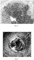
- the urea which constitutes these droplets therefore remains for a long time in contact with the wall of the separator and is therefore subject to degradation with the formation of by-products which solidify, in turn retaining new urea with growth of the layer in contact with the separator wall until the partial, and sometimes total, clogging of the upper part of the separator itself, as is evident from figure 2 where the upper part of a separator is photographed.
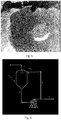
- a further problem is represented by the detachment of the crusts which, falling into the lower area of the separator, clog however the outlet or, if they have a limited size, reach the suction of the pump causing cavitation, as shown in figure 3 and in figure 4 .
- the objective of the present invention is to overcome the drawbacks and problems previously indicated that characterize the state of the art.
- the Applicant has in fact surprisingly found a method for washing a separator for processing molten urea which prevents the formation of encrustations of urea on the internal surface of the walls of the separator itself.
- the Applicant has also found a separator for processing molten urea which allows the washing of the walls of the separator itself to be effected in a particularly effective way.
- the present invention therefore relates to a method for washing a separator for processing molten urea, comprising a continuous recirculation of at least a portion of the molten urea taken from the bottom of said separator, wherein this portion of molten urea withdrawn is continuously flushed on the upper portion of the cylindrical side wall of the separator, said flow being distributed along the whole circumference of the internal cylindrical side wall of said separator.
- the supply of the recirculation or flow of the portion of molten urea withdrawn and recirculated is preferably positioned above the tangent line(s) that connect the upper portion of the internal cylindrical side wall of the separator and the upper cap that forms the separator roof.
- the ratio between the quantity of recycled urea and the total quantity of urea leaving the separator is preferably within a range of 66% to 80% by weight.
- This ratio makes it possible to create a flow of recycled urea such as to guarantee the complete coverage of the whole circumference of the cylindrical wall of the separator, thus achieving an effective continuous washing of the wall, without however recycling a greater quantity of urea than necessary.
- the ratio between the quantity of recycled urea and the quantity of urea fed to the melamine synthesis reactor preferably ranges from 200 to 400% by weight.
- the dimensions of the separator are defined in relation to the flow-rate of steam to be discharged upwards, which, in turn, is in relation to the concentration and flow-rate of diluted urea that is fed to the separator, the latter being, in turn, in relation to the quantity of urea fed to the reactor, the quantity of urea recycled, i.e. the degree of recycling, can also be calculated on the basis of the flow-rate/quantity of urea fed or to be fed to the reactor.
- the recycling of urea is carried out by distributing a liquid film of urea over the whole circumference of the cylindrical side wall, without the presence of droplets in free fall and/or without the formation of nebulized phases.
- the present invention therefore relates to a separator for processing molten urea characterized in that it comprises at least one distributor element suitable for feeding recycled urea to said separator, wherein said distributor element is positioned above the tangent line(s) that connect the upper portion of the internal cylindrical side wall of the separator and the upper cap which forms the roof of the separator.
- Said at least one distributor element can be positioned internally or externally with respect to the separator.
- Said at least one distributor element when positioned externally, can provide at least one unidirectional tangential inlet, at least one bidirectional tangential inlet or can be produced by means of a coaxial circumferential distributor.
- coaxial refers to the position of the distributor with respect to the separator.
- Said coaxial circumferential distributor can be composed of a half-pipe, welded on the external surface of the separator, wherein there are a series of openings on said external surface of the separator, suitable for feeding and distributing the recirculating urea along the whole circumference of the cylindrical side wall inside the separator.
- Said openings can internally provide a deflector suitable for preventing the urea, exiting from the openings, from becoming detached from the internal wall of the separator.
- Said at least one distributor element when positioned internally, can consist of a coaxial pipe provided with openings, preferably holes, suitable for feeding and distributing the recirculating urea along the whole circumference of the internal cylindrical side wall of the separator.
- the distributor element positioned externally can comprise at least four unidirectional tangential inlets.
- the above-mentioned distributor element comprises four unidirectional tangential inlets, said inlets are positioned at 90° with respect to each other.
- the distributor element positioned externally can comprise at least three bidirectional tangential inlets.
- the above-mentioned distributor element comprises three bidirectional tangential inlets, said inlets are positioned at 120° with respect to each other.
- this can preferably comprise at least one unidirectional distributor element, positioned internally and coaxial with respect to the separator, wherein said distributor element can be a pipe provided with openings or perforated, said openings or even more preferably the holes of said pipe preferably facing the side wall of the separator, even more preferably with a downward angle of 30° with respect to the horizontal plane, so that the urea to be recycled is directed towards the lower part of the separator .
- said distributor element can be a pipe provided with openings or perforated, said openings or even more preferably the holes of said pipe preferably facing the side wall of the separator, even more preferably with a downward angle of 30° with respect to the horizontal plane, so that the urea to be recycled is directed towards the lower part of the separator .
- Horizontal plane refers to a plane perpendicular to the side wall of the separator, considered as the vertical plane.
- this can preferably comprise at least one bidirectional distributor element, positioned internally and coaxial with respect to the separator, wherein said distributor element can be a pipe provided with openings or with holes, the openings or more preferably the holes of said pipe preferably facing the side wall of the separator, more preferably with a downward angle of 30° with respect to the horizontal plane, so that a portion of the urea to be recycled is directed towards the lower part of the separator, even more preferably with an alternation of openings or holes, wherein the washing openings or holes of the inner wall of the separator are at a downward angle of 30° with respect to the horizontal plane, so that a portion of the urea to be recycled is directed towards the lower part of the separator and the washing openings or holes of the upper part of the distributor have an upward angle of 90° with respect to the horizontal plane, so that a portion of the urea to be recycled is directed towards the upper part of the distributor itself, thus keeping the upper surface of the distributor continuously flush
- the lower part of the separator refers to the part of the separator from which concentrated urea exits, whereas the upper part of the separator refers to the part of the separator where the vapour outlet pipe is located.
- the distributor element according to the present invention is particularly advantageous in that it prevents the urea to be recycled, fed for washing the separator, from being entrained upwards by the vapours that are released from the diluted urea during its concentration, with consequent clogging of the vapour outlet area.
- a further advantage of the distributor element of the separator according to the present invention is that it is capable of feeding the urea so as to form a liquid film over the whole circumference without the presence of droplets in free fall and/or without the formation of nebulized phases.
- said distributor elements allow the formation of surfaces which can in turn create a support for the formation of crusts of urea, to be avoided or in any case reduced as much as possible.
- the present invention further relates to a plant for the production of high-pressure melamine comprising a separator for processing molten urea which comprises at least one distributor element suitable for feeding recycled urea to said separator, wherein said distributor element is positioned above the tangent line(s) which connect the upper portion of the cylindrical side wall of the separator and the upper cap that forms the roof of the separator.
- the separator indicated with 10 provides an outlet duct for concentrated urea 6 wherein the stream of concentrated urea is partly directed, by means of a suitable pump 7, to the synthesis of melamine 8 and partly directed to recycling 9 to carry out the washing process of the separator 10 according to the present invention.
- the urea to be recycled is fed in 5 to the distributor element 11.
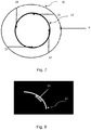
- Figure 7 shows a distributor element 11 positioned externally with respect to the wall 12 of the separator 10 with four tangential inlets 13 of the unidirectional type, each inlet 13 positioned at an angle of 90° with respect to the direction of another inlet 13.
- Figure 8 shows a detail of a bidirectional tangential inlet 13 of a distributor element 11 (not shown in the figure).
- Figure 9 shows a separator 10 with the distributor element 11 positioned internally with respect to the wall 12 of the separator. More specifically, figure 9a shows the distributor element 11 consisting of a perforated pipe 14 with holes 15 or with alternating holes 15 and 15' in the case of a bidirectional distributor.
- Figure 9b shows the detail of the hole 15 of the distributor element 11 of figure 9 , produced by means of a perforated pipe 14 with unidirectional distribution, wherein said hole 15 faces the side wall 12 of the separator 10 at a downward angle of 30° with respect to the horizontal plane, so that the urea to be recycled is directed towards the lower part of the separator 10.
- Figure 9c shows the detail of the holes 15 and 15' of the distributor element 11 of figure 9 , produced by means of a perforated pipe 14 with bidirectional distribution, wherein said perforated pipe 14 provides an alternation of holes 15 and 15', wherein the washing holes 15 of the inner wall 12 of the separator 10 have a downward angle of 30° with respect to the horizontal plane, so that a portion of the urea to be recycled is directed towards the lower part of the separator 10 and the washing holes 15' of the upper part of the distributor 11 have an upward angle of 90° with respect to the horizontal plane, so that a portion of the urea to be recycled is directed towards the upper part of the distributor 11, thus avoiding the retention of urea on the upper surface of the distributor itself and the consequent formation of encrustations.
- Figure 10 shows a distributor element 11 positioned externally with respect to the separator 10 and coaxial to the separator 10, produced by means of a half-pipe welded to the external surface of the separator 10, wherein 16 indicates the feeding holes of the urea to be recycled, present in the wall 12 of the separator 10 and 17 the internal deflector.
- Figure 10a shows the detail of the external distributor 11, produced by means of a welded half-pipe, wherein the distribution is effected through inlet holes 16 and an internal deflector 17.
Landscapes
- Chemical & Material Sciences (AREA)
- Engineering & Computer Science (AREA)
- Mechanical Engineering (AREA)
- Organic Chemistry (AREA)
- Chemical Kinetics & Catalysis (AREA)
- Organic Low-Molecular-Weight Compounds And Preparation Thereof (AREA)
Applications Claiming Priority (1)
| Application Number | Priority Date | Filing Date | Title |
|---|---|---|---|
| IT102020000010990A IT202000010990A1 (it) | 2020-05-14 | 2020-05-14 | Metodo di lavaggio di un separatore per urea fusa e relativo apparato separatore |
Publications (3)
| Publication Number | Publication Date |
|---|---|
| EP3909694A1 true EP3909694A1 (fr) | 2021-11-17 |
| EP3909694C0 EP3909694C0 (fr) | 2023-09-13 |
| EP3909694B1 EP3909694B1 (fr) | 2023-09-13 |
Family
ID=71994793
Family Applications (1)
| Application Number | Title | Priority Date | Filing Date |
|---|---|---|---|
| EP21173729.1A Active EP3909694B1 (fr) | 2020-05-14 | 2021-05-13 | Procédé de lavage d'un séparateur pour le traitement d'urée fondue et équipement de séparation associé |
Country Status (3)
| Country | Link |
|---|---|
| EP (1) | EP3909694B1 (fr) |
| CN (1) | CN113663605A (fr) |
| IT (1) | IT202000010990A1 (fr) |
Citations (7)
| Publication number | Priority date | Publication date | Assignee | Title |
|---|---|---|---|---|
| GB1215836A (en) * | 1967-04-26 | 1970-12-16 | Basf Ag | Avoiding encrustation of urea and its thermal decomposition products in a drop separator |
| US4241744A (en) * | 1979-07-02 | 1980-12-30 | Jordan Nathaniel Sr | Cleaning system for tanks |
| DE20020882U1 (de) * | 2000-12-08 | 2001-03-29 | Senkingwerk Gmbh, 31137 Hildesheim | Vorrichtung zur Reinigung bzw. Desinfektion unzugänglicher wasserführender Innenräume von Waschgeräten |
| US20040226587A1 (en) * | 2003-05-16 | 2004-11-18 | Michel Lemire | Sand removal system |
| EP1792666A2 (fr) * | 2005-12-01 | 2007-06-06 | Sigl, Josef | Nettoyage automatisé de conteneurs ouverts |
| EP2226450A2 (fr) * | 2009-03-06 | 2010-09-08 | Kühling & Hauers Schwimmbadtechnik GmbH | Système de collecte d'eau de débordement pour piscines, bains à remous, bains à exercices, bains de traitement et analogues |
| FR3031982A1 (fr) * | 2015-01-22 | 2016-07-29 | Aguirre David Blanco | Dispositif destine au nettoyage d'un vinificateur |
Family Cites Families (3)
| Publication number | Priority date | Publication date | Assignee | Title |
|---|---|---|---|---|
| IT1240675B (it) * | 1990-04-24 | 1993-12-17 | Snam Progetti | Procedimento per la concentrazione sotto vuoto di soluzioni di urea |
| CN203209057U (zh) * | 2013-04-26 | 2013-09-25 | 东莞市杉杉电池材料有限公司 | 一种带自动清洗装置的电解液反应釜 |
| CN206995883U (zh) * | 2017-06-23 | 2018-02-13 | 张晓霞 | 一种中药浓缩设备 |
-
2020
- 2020-05-14 IT IT102020000010990A patent/IT202000010990A1/it unknown
-
2021
- 2021-05-13 EP EP21173729.1A patent/EP3909694B1/fr active Active
- 2021-05-13 CN CN202110524807.5A patent/CN113663605A/zh active Pending
Patent Citations (7)
| Publication number | Priority date | Publication date | Assignee | Title |
|---|---|---|---|---|
| GB1215836A (en) * | 1967-04-26 | 1970-12-16 | Basf Ag | Avoiding encrustation of urea and its thermal decomposition products in a drop separator |
| US4241744A (en) * | 1979-07-02 | 1980-12-30 | Jordan Nathaniel Sr | Cleaning system for tanks |
| DE20020882U1 (de) * | 2000-12-08 | 2001-03-29 | Senkingwerk Gmbh, 31137 Hildesheim | Vorrichtung zur Reinigung bzw. Desinfektion unzugänglicher wasserführender Innenräume von Waschgeräten |
| US20040226587A1 (en) * | 2003-05-16 | 2004-11-18 | Michel Lemire | Sand removal system |
| EP1792666A2 (fr) * | 2005-12-01 | 2007-06-06 | Sigl, Josef | Nettoyage automatisé de conteneurs ouverts |
| EP2226450A2 (fr) * | 2009-03-06 | 2010-09-08 | Kühling & Hauers Schwimmbadtechnik GmbH | Système de collecte d'eau de débordement pour piscines, bains à remous, bains à exercices, bains de traitement et analogues |
| FR3031982A1 (fr) * | 2015-01-22 | 2016-07-29 | Aguirre David Blanco | Dispositif destine au nettoyage d'un vinificateur |
Also Published As
| Publication number | Publication date |
|---|---|
| CN113663605A (zh) | 2021-11-19 |
| IT202000010990A1 (it) | 2021-11-14 |
| EP3909694C0 (fr) | 2023-09-13 |
| EP3909694B1 (fr) | 2023-09-13 |
Similar Documents
| Publication | Publication Date | Title |
|---|---|---|
| CN1933902B (zh) | 制备聚合物的方法和设备 | |
| US20130129576A1 (en) | Multiphase catalytic tower-type impinging-stream reactor | |
| DK168632B1 (da) | Polymerisationsreaktor med fluidiseret leje og fremgangsmåde til polymerisering ved brug af reaktoren | |
| KR101654804B1 (ko) | 슬러리 기포탑 반응기 | |
| SU936795A3 (ru) | Установка дл гранулировани и/или покрыти гранул оболочкой в фонтанирующем слое | |
| US6290775B1 (en) | Fluidized bed reactor and a process of using the same | |
| KR102256418B1 (ko) | 반응기 유출물로부터 개선된 암모니아 제거 | |
| WO2015031087A1 (fr) | Unités de réacteurs à lit fluidisé couplées en série comprenant des ensembles plénums cycloniques et procédés d'hydrofluoration associés | |
| US3390402A (en) | Apparatus for countercurrent washing of mother liquor from solid products | |
| CN103304692A (zh) | 烯烃聚合装置和烯烃聚合方法 | |
| EP2585212B1 (fr) | Réacteur horizontal, haute pression à mélamine et procédé | |
| EP3909694B1 (fr) | Procédé de lavage d'un séparateur pour le traitement d'urée fondue et équipement de séparation associé | |
| EP3394116B1 (fr) | Procédé pour retirer des polyoléfines | |
| EP2167227B1 (fr) | Appareil et procédé pour un enlèvement par le dessus de matière granulaire depuis un réacteur de dépôt à lit fluidisé | |
| CN110201610B (zh) | 气体分布器和反应器 | |
| AU2009260114B2 (en) | Flash tanks | |
| CN117202977A (zh) | 通过离心式除雾器从气流中分离液体液滴的设备和方法 | |
| CN110099741B (zh) | 包含导流器的流化催化反应器 | |
| CN113631593A (zh) | 中心喷射管 | |
| JP2003112037A (ja) | 少なくとも1つのガス相および液相からなる混合物の内部分離装置 | |
| TWI666056B (zh) | 用於淬冷流出物的改進的煙霧消除器操作 | |
| CN221964881U (zh) | 一种铑基催化剂回收装置 | |
| US20240326003A1 (en) | Systems for Polymer Fines Recovery | |
| US6117972A (en) | Introducing steam into polymer dispersions | |
| KR20220062220A (ko) | 육불화우라늄의 열가수분해로 이산화우라늄 분말을 제조하는 반응 챔버 |
Legal Events
| Date | Code | Title | Description |
|---|---|---|---|
| PUAI | Public reference made under article 153(3) epc to a published international application that has entered the european phase |
Free format text: ORIGINAL CODE: 0009012 |
|
| STAA | Information on the status of an ep patent application or granted ep patent |
Free format text: STATUS: THE APPLICATION HAS BEEN PUBLISHED |
|
| AK | Designated contracting states |
Kind code of ref document: A1 Designated state(s): AL AT BE BG CH CY CZ DE DK EE ES FI FR GB GR HR HU IE IS IT LI LT LU LV MC MK MT NL NO PL PT RO RS SE SI SK SM TR |
|
| B565 | Issuance of search results under rule 164(2) epc |
Effective date: 20211007 |
|
| STAA | Information on the status of an ep patent application or granted ep patent |
Free format text: STATUS: REQUEST FOR EXAMINATION WAS MADE |
|
| 17P | Request for examination filed |
Effective date: 20220512 |
|
| RBV | Designated contracting states (corrected) |
Designated state(s): AL AT BE BG CH CY CZ DE DK EE ES FI FR GB GR HR HU IE IS IT LI LT LU LV MC MK MT NL NO PL PT RO RS SE SI SK SM TR |
|
| GRAP | Despatch of communication of intention to grant a patent |
Free format text: ORIGINAL CODE: EPIDOSNIGR1 |
|
| STAA | Information on the status of an ep patent application or granted ep patent |
Free format text: STATUS: GRANT OF PATENT IS INTENDED |
|
| INTG | Intention to grant announced |
Effective date: 20230515 |
|
| GRAS | Grant fee paid |
Free format text: ORIGINAL CODE: EPIDOSNIGR3 |
|
| GRAA | (expected) grant |
Free format text: ORIGINAL CODE: 0009210 |
|
| STAA | Information on the status of an ep patent application or granted ep patent |
Free format text: STATUS: THE PATENT HAS BEEN GRANTED |
|
| AK | Designated contracting states |
Kind code of ref document: B1 Designated state(s): AL AT BE BG CH CY CZ DE DK EE ES FI FR GB GR HR HU IE IS IT LI LT LU LV MC MK MT NL NO PL PT RO RS SE SI SK SM TR |
|
| REG | Reference to a national code |
Ref country code: CH Ref legal event code: EP |
|
| RAP2 | Party data changed (patent owner data changed or rights of a patent transferred) |
Owner name: PROMAN AG |
|
| REG | Reference to a national code |
Ref country code: DE Ref legal event code: R096 Ref document number: 602021005067 Country of ref document: DE |
|
| REG | Reference to a national code |
Ref country code: IE Ref legal event code: FG4D |
|
| U01 | Request for unitary effect filed |
Effective date: 20231010 |
|
| U07 | Unitary effect registered |
Designated state(s): AT BE BG DE DK EE FI FR IT LT LU LV MT NL PT SE SI Effective date: 20231016 |
|
| PG25 | Lapsed in a contracting state [announced via postgrant information from national office to epo] |
Ref country code: GR Free format text: LAPSE BECAUSE OF FAILURE TO SUBMIT A TRANSLATION OF THE DESCRIPTION OR TO PAY THE FEE WITHIN THE PRESCRIBED TIME-LIMIT Effective date: 20231214 |
|
| PG25 | Lapsed in a contracting state [announced via postgrant information from national office to epo] |
Ref country code: RS Free format text: LAPSE BECAUSE OF FAILURE TO SUBMIT A TRANSLATION OF THE DESCRIPTION OR TO PAY THE FEE WITHIN THE PRESCRIBED TIME-LIMIT Effective date: 20230913 Ref country code: NO Free format text: LAPSE BECAUSE OF FAILURE TO SUBMIT A TRANSLATION OF THE DESCRIPTION OR TO PAY THE FEE WITHIN THE PRESCRIBED TIME-LIMIT Effective date: 20231213 Ref country code: HR Free format text: LAPSE BECAUSE OF FAILURE TO SUBMIT A TRANSLATION OF THE DESCRIPTION OR TO PAY THE FEE WITHIN THE PRESCRIBED TIME-LIMIT Effective date: 20230913 Ref country code: GR Free format text: LAPSE BECAUSE OF FAILURE TO SUBMIT A TRANSLATION OF THE DESCRIPTION OR TO PAY THE FEE WITHIN THE PRESCRIBED TIME-LIMIT Effective date: 20231214 |
|
| PG25 | Lapsed in a contracting state [announced via postgrant information from national office to epo] |
Ref country code: IS Free format text: LAPSE BECAUSE OF FAILURE TO SUBMIT A TRANSLATION OF THE DESCRIPTION OR TO PAY THE FEE WITHIN THE PRESCRIBED TIME-LIMIT Effective date: 20240113 |
|
| PG25 | Lapsed in a contracting state [announced via postgrant information from national office to epo] |
Ref country code: ES Free format text: LAPSE BECAUSE OF FAILURE TO SUBMIT A TRANSLATION OF THE DESCRIPTION OR TO PAY THE FEE WITHIN THE PRESCRIBED TIME-LIMIT Effective date: 20230913 |
|
| PG25 | Lapsed in a contracting state [announced via postgrant information from national office to epo] |
Ref country code: SM Free format text: LAPSE BECAUSE OF FAILURE TO SUBMIT A TRANSLATION OF THE DESCRIPTION OR TO PAY THE FEE WITHIN THE PRESCRIBED TIME-LIMIT Effective date: 20230913 Ref country code: RO Free format text: LAPSE BECAUSE OF FAILURE TO SUBMIT A TRANSLATION OF THE DESCRIPTION OR TO PAY THE FEE WITHIN THE PRESCRIBED TIME-LIMIT Effective date: 20230913 Ref country code: IS Free format text: LAPSE BECAUSE OF FAILURE TO SUBMIT A TRANSLATION OF THE DESCRIPTION OR TO PAY THE FEE WITHIN THE PRESCRIBED TIME-LIMIT Effective date: 20240113 Ref country code: ES Free format text: LAPSE BECAUSE OF FAILURE TO SUBMIT A TRANSLATION OF THE DESCRIPTION OR TO PAY THE FEE WITHIN THE PRESCRIBED TIME-LIMIT Effective date: 20230913 Ref country code: CZ Free format text: LAPSE BECAUSE OF FAILURE TO SUBMIT A TRANSLATION OF THE DESCRIPTION OR TO PAY THE FEE WITHIN THE PRESCRIBED TIME-LIMIT Effective date: 20230913 Ref country code: SK Free format text: LAPSE BECAUSE OF FAILURE TO SUBMIT A TRANSLATION OF THE DESCRIPTION OR TO PAY THE FEE WITHIN THE PRESCRIBED TIME-LIMIT Effective date: 20230913 |
|
| PG25 | Lapsed in a contracting state [announced via postgrant information from national office to epo] |
Ref country code: PL Free format text: LAPSE BECAUSE OF FAILURE TO SUBMIT A TRANSLATION OF THE DESCRIPTION OR TO PAY THE FEE WITHIN THE PRESCRIBED TIME-LIMIT Effective date: 20230913 |
|
| REG | Reference to a national code |
Ref country code: DE Ref legal event code: R097 Ref document number: 602021005067 Country of ref document: DE |
|
| U20 | Renewal fee for the european patent with unitary effect paid |
Year of fee payment: 4 Effective date: 20240528 |
|
| PLBE | No opposition filed within time limit |
Free format text: ORIGINAL CODE: 0009261 |
|
| STAA | Information on the status of an ep patent application or granted ep patent |
Free format text: STATUS: NO OPPOSITION FILED WITHIN TIME LIMIT |
|
| 26N | No opposition filed |
Effective date: 20240614 |
|
| PG25 | Lapsed in a contracting state [announced via postgrant information from national office to epo] |
Ref country code: MC Free format text: LAPSE BECAUSE OF FAILURE TO SUBMIT A TRANSLATION OF THE DESCRIPTION OR TO PAY THE FEE WITHIN THE PRESCRIBED TIME-LIMIT Effective date: 20230913 |
|
| PG25 | Lapsed in a contracting state [announced via postgrant information from national office to epo] |
Ref country code: MC Free format text: LAPSE BECAUSE OF FAILURE TO SUBMIT A TRANSLATION OF THE DESCRIPTION OR TO PAY THE FEE WITHIN THE PRESCRIBED TIME-LIMIT Effective date: 20230913 |
|
| PG25 | Lapsed in a contracting state [announced via postgrant information from national office to epo] |
Ref country code: IE Free format text: LAPSE BECAUSE OF NON-PAYMENT OF DUE FEES Effective date: 20240513 |
|
| U20 | Renewal fee for the european patent with unitary effect paid |
Year of fee payment: 5 Effective date: 20250527 |
|
| U1N | Appointed representative for the unitary patent procedure changed after the registration of the unitary effect |
Representative=s name: BIRD & BIRD SOCIETA TRA AVVOCATI S.R.L.; IT |
|
| PGFP | Annual fee paid to national office [announced via postgrant information from national office to epo] |
Ref country code: CH Payment date: 20250601 Year of fee payment: 5 |
|
| PG25 | Lapsed in a contracting state [announced via postgrant information from national office to epo] |
Ref country code: CY Free format text: LAPSE BECAUSE OF FAILURE TO SUBMIT A TRANSLATION OF THE DESCRIPTION OR TO PAY THE FEE WITHIN THE PRESCRIBED TIME-LIMIT; INVALID AB INITIO Effective date: 20210513 |
|
| PG25 | Lapsed in a contracting state [announced via postgrant information from national office to epo] |
Ref country code: HU Free format text: LAPSE BECAUSE OF FAILURE TO SUBMIT A TRANSLATION OF THE DESCRIPTION OR TO PAY THE FEE WITHIN THE PRESCRIBED TIME-LIMIT; INVALID AB INITIO Effective date: 20210513 |
|
| GBPC | Gb: european patent ceased through non-payment of renewal fee |
Effective date: 20250513 |
|
| REG | Reference to a national code |
Ref country code: CH Ref legal event code: R14 Free format text: ST27 STATUS EVENT CODE: U-0-0-R10-R14 (AS PROVIDED BY THE NATIONAL OFFICE) Effective date: 20260311 Ref country code: CH Ref legal event code: R17 Free format text: ST27 STATUS EVENT CODE: U-0-0-R10-R17 (AS PROVIDED BY THE NATIONAL OFFICE) Effective date: 20260311 |
|
| REG | Reference to a national code |
Ref country code: CH Ref legal event code: S20 Free format text: ST27 STATUS EVENT CODE: U-0-0-S10-S20 (AS PROVIDED BY THE NATIONAL OFFICE) Effective date: 20260317 |
|
| U1K | Transfer of rights of the unitary patent after the registration of the unitary effect |
Owner name: EUROTECNICA CONTRACTORS AND ENGINEERS S.P.A.; IT |
|
| PG25 | Lapsed in a contracting state [announced via postgrant information from national office to epo] |
Ref country code: GB Free format text: LAPSE BECAUSE OF NON-PAYMENT OF DUE FEES Effective date: 20250513 |