EP3909701B1 - Plattformvorrichtung zur platzierung von werkstücken mit einem relativ zur oberfläche der platzierungsplattform frei einwärts und auswärts beweglichen werkstückpositionierungselement - Google Patents
Plattformvorrichtung zur platzierung von werkstücken mit einem relativ zur oberfläche der platzierungsplattform frei einwärts und auswärts beweglichen werkstückpositionierungselement Download PDFInfo
- Publication number
- EP3909701B1 EP3909701B1 EP21180951.2A EP21180951A EP3909701B1 EP 3909701 B1 EP3909701 B1 EP 3909701B1 EP 21180951 A EP21180951 A EP 21180951A EP 3909701 B1 EP3909701 B1 EP 3909701B1
- Authority
- EP
- European Patent Office
- Prior art keywords
- workpiece
- axis direction
- placement platform
- positioning member
- workpieces
- Prior art date
- Legal status (The legal status is an assumption and is not a legal conclusion. Google has not performed a legal analysis and makes no representation as to the accuracy of the status listed.)
- Active
Links
Images


Classifications
-
- B—PERFORMING OPERATIONS; TRANSPORTING
- B21—MECHANICAL METAL-WORKING WITHOUT ESSENTIALLY REMOVING MATERIAL; PUNCHING METAL
- B21D—WORKING OR PROCESSING OF SHEET METAL OR METAL TUBES, RODS OR PROFILES WITHOUT ESSENTIALLY REMOVING MATERIAL; PUNCHING METAL
- B21D43/00—Feeding, positioning or storing devices combined with, or arranged in, or specially adapted for use in connection with, apparatus for working or processing sheet metal, metal tubes or metal profiles; Associations therewith of cutting devices
- B21D43/003—Positioning devices
-
- B—PERFORMING OPERATIONS; TRANSPORTING
- B21—MECHANICAL METAL-WORKING WITHOUT ESSENTIALLY REMOVING MATERIAL; PUNCHING METAL
- B21D—WORKING OR PROCESSING OF SHEET METAL OR METAL TUBES, RODS OR PROFILES WITHOUT ESSENTIALLY REMOVING MATERIAL; PUNCHING METAL
- B21D43/00—Feeding, positioning or storing devices combined with, or arranged in, or specially adapted for use in connection with, apparatus for working or processing sheet metal, metal tubes or metal profiles; Associations therewith of cutting devices
- B21D43/20—Storage arrangements; Piling or unpiling
-
- B—PERFORMING OPERATIONS; TRANSPORTING
- B21—MECHANICAL METAL-WORKING WITHOUT ESSENTIALLY REMOVING MATERIAL; PUNCHING METAL
- B21D—WORKING OR PROCESSING OF SHEET METAL OR METAL TUBES, RODS OR PROFILES WITHOUT ESSENTIALLY REMOVING MATERIAL; PUNCHING METAL
- B21D43/00—Feeding, positioning or storing devices combined with, or arranged in, or specially adapted for use in connection with, apparatus for working or processing sheet metal, metal tubes or metal profiles; Associations therewith of cutting devices
- B21D43/26—Stops
-
- B—PERFORMING OPERATIONS; TRANSPORTING
- B23—MACHINE TOOLS; METAL-WORKING NOT OTHERWISE PROVIDED FOR
- B23Q—DETAILS, COMPONENTS, OR ACCESSORIES FOR MACHINE TOOLS, e.g. ARRANGEMENTS FOR COPYING OR CONTROLLING; MACHINE TOOLS IN GENERAL CHARACTERISED BY THE CONSTRUCTION OF PARTICULAR DETAILS OR COMPONENTS; COMBINATIONS OR ASSOCIATIONS OF METAL-WORKING MACHINES, NOT DIRECTED TO A PARTICULAR RESULT
- B23Q3/00—Devices holding, supporting, or positioning work or tools, of a kind normally removable from the machine
- B23Q3/18—Devices holding, supporting, or positioning work or tools, of a kind normally removable from the machine for positioning only
-
- B—PERFORMING OPERATIONS; TRANSPORTING
- B65—CONVEYING; PACKING; STORING; HANDLING THIN OR FILAMENTARY MATERIAL
- B65H—HANDLING THIN OR FILAMENTARY MATERIAL, e.g. SHEETS, WEBS, CABLES
- B65H31/00—Pile receivers
- B65H31/24—Pile receivers multiple or compartmented, e.d. for alternate, programmed, or selective filling
-
- B—PERFORMING OPERATIONS; TRANSPORTING
- B21—MECHANICAL METAL-WORKING WITHOUT ESSENTIALLY REMOVING MATERIAL; PUNCHING METAL
- B21D—WORKING OR PROCESSING OF SHEET METAL OR METAL TUBES, RODS OR PROFILES WITHOUT ESSENTIALLY REMOVING MATERIAL; PUNCHING METAL
- B21D43/00—Feeding, positioning or storing devices combined with, or arranged in, or specially adapted for use in connection with, apparatus for working or processing sheet metal, metal tubes or metal profiles; Associations therewith of cutting devices
- B21D43/20—Storage arrangements; Piling or unpiling
- B21D43/22—Devices for piling sheets
-
- B—PERFORMING OPERATIONS; TRANSPORTING
- B21—MECHANICAL METAL-WORKING WITHOUT ESSENTIALLY REMOVING MATERIAL; PUNCHING METAL
- B21D—WORKING OR PROCESSING OF SHEET METAL OR METAL TUBES, RODS OR PROFILES WITHOUT ESSENTIALLY REMOVING MATERIAL; PUNCHING METAL
- B21D5/00—Bending sheet metal along straight lines, e.g. to form simple curves
- B21D5/02—Bending sheet metal along straight lines, e.g. to form simple curves on press brakes without making use of clamping means
- B21D5/0281—Workpiece supporting devices
-
- B—PERFORMING OPERATIONS; TRANSPORTING
- B23—MACHINE TOOLS; METAL-WORKING NOT OTHERWISE PROVIDED FOR
- B23Q—DETAILS, COMPONENTS, OR ACCESSORIES FOR MACHINE TOOLS, e.g. ARRANGEMENTS FOR COPYING OR CONTROLLING; MACHINE TOOLS IN GENERAL CHARACTERISED BY THE CONSTRUCTION OF PARTICULAR DETAILS OR COMPONENTS; COMBINATIONS OR ASSOCIATIONS OF METAL-WORKING MACHINES, NOT DIRECTED TO A PARTICULAR RESULT
- B23Q7/00—Arrangements for handling work specially combined with or arranged in, or specially adapted for use in connection with, machine tools, e.g. for conveying, loading, positioning, discharging, sorting
- B23Q7/16—Loading work on to conveyors; Arranging work on conveyors, e.g. varying spacing between individual workpieces
- B23Q7/18—Orienting work on conveyors
-
- B—PERFORMING OPERATIONS; TRANSPORTING
- B65—CONVEYING; PACKING; STORING; HANDLING THIN OR FILAMENTARY MATERIAL
- B65G—TRANSPORT OR STORAGE DEVICES, e.g. CONVEYORS FOR LOADING OR TIPPING, SHOP CONVEYOR SYSTEMS OR PNEUMATIC TUBE CONVEYORS
- B65G57/00—Stacking of articles
Definitions
- the present invention relates to a workpiece placement platform device on which to place a stack of plate-shaped workpieces for feeding each of the workpiece to a plate material processing machine such as a laser processing machine or a press brake, for example. More specifically, the present invention relates to a workpiece placement platform of a workpiece placement platform device with a workpiece positioning member which is provided to be movable in and out relative to the workpiece placement surface of the placement platform for placing workpieces on the placement platform in the work placement device, and which, in the case where the workpieces are, for example, precut small workpieces such as cut materials, partitions the workpiece placement surface into sections and positions the workpieces.
- An industrial robot is sometimes used as a plate material feed device to feed plate-shaped workpieces to a plate material processing machine such as a press brake, for example.
- a plate material processing machine such as a press brake
- the workpieces are positioned by contacting workpiece positioning members on the workpiece placement surface of the workpiece placement platform. Then, the workpiece thus positioned is sucked and fed by a vacuum pad or the like provided to the plate material feed device (see Patent Literature 1, for example).
- Patent Literature 1 Japanese Patent Application Publication No. 2014-155965
- WO 2016/162078 A1 discloses a workpiece placement platform device according to the preamble of the appended claim 1.
- an object of the present invention is to provide a workpiece placement platform device having a workpiece positioning member movable in and out relative to the upper surface of a placement platform on which to place workpieces.
- the present invention solving the above object, is defined in independent claim 1. Preferred embodiments are laid down in the dependent claims.
- the workpiece positioning member which partitions the workpiece placement surface of the placement platform into sections is provided to be movable in and out relative to the workpiece placement surface.
- the workpiece positioning member is not used, large workpieces can be placed and positioned on the workpiece placement surface.
- some workpieces placed on the workpiece placement surface are positioned using the workpiece positioning member.
- the workpiece placement surface of the placement platform is partitioned and used as sections. This reduces wasted regions on the workpiece placement surface. Accordingly, more workpieces can be placed and positioned.
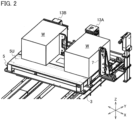
- the mount 3 is provided with a Y-axis direction guide member 9. Further, on this guide member 9, a positioning block 11 integrally provided with the X-axis direction positioning member 7 is provided such that its position is movable. Thus, the position of the X-axis direction positioning member 7 is adjustable according to the size of the workpieces W in the Y-axis direction.
- Y-axis direction positioning members 13A and 13B that position another side edge (side edge in the Y-axis direction) of the stack of workpieces W on the placement platform 5 by contacting the side edge, the Y-axis direction positioning members 13A and 13B being spaced from each other in the X-axis direction.
- a positioning member equivalent to the X-axis direction positioning member 7 at a position for the empty space. In this case, however, this positioning member will need to be detached if workpieces W are to be placed on the entire upper surface of the placement platform 5 as illustrated in Fig. 1 .
- the X-axis direction positioning member is made of metal and is heavy, the work of attaching or detaching the X-axis direction positioning member is troublesome.
- the X-axis direction positioning member for the empty space is configured to be easily movable in and out relative to the workpiece placement surface of the placement platform 5.
- one Y-axis direction positioning member 13B is provided such that its position is adjustable in the X-axis direction.
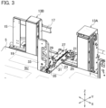
- a support pillar 15 (see Fig. 3 ) is provided on an end side of the mount 3 in the Y-axis direction at a position away from the Y-axis direction positioning member 13A, and an upper guide member 17 extending horizontally in the X-axis direction is integrally provided on an upper portion of the support pillar 15.
- a lower guide member 19 is provided in parallel to the upper guide member 17, the lower guide member 19 being located at a position below the upper guide member 17. Further, the Y-axis direction positioning member 13B is supported on the upper and lower guide members 17 and 19 such that its position is adjustable in the X-axis direction.
- a support block 21 is provided between the Y-axis direction positioning members 13A and 13B around the end of the mount 3 in the Y-axis direction.
- the proximal end side of a pivot arm 23 is turnably provided on this support block 21, the pivot arm 23 being pivotable about a vertical axis.
- the pivot arm 23 forms an in-out member movable in and out relative to the upper surface (workpiece placement surface) 5U of the placement platform 5 by pivoting horizontally.
- the configuration that moves the in-out member (pivot arm 23) in and out relative to the upper surface 5U of the placement platform 5 can be a configuration that moves the in-out member in the Y-axis direction, instead of the configuration that pivots the in-out member horizontally as described above.
- the support block 21 is provided with a stopper 25 so that the longitudinal direction of the pivot arm 23 can be parallel to the Y-axis direction when the pivot arm 23 is positioned above the upper surface 5U of the placement platform 5.
- the pivot arm 23 contacts the stopper 25 and is hence positioned in parallel to the Y-axis direction.
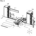
- a guide member 27 parallel to the longitudinal direction of the pivot arm 23.
- a slide block 29 is provided to be movable for adjustment.
- the slide block 29 is provided with a lock lever 31 having a fixing screw (not illustrated) capable of pressing (fastening) the guide member 27 with its distal end.
- the slide block 29 can be moved along the guide member 27 for adjustment and fixed as the adjusted position.
- the slide block 29 is provided with a workpiece positioning member 33 capable of positioning X-axis direction side edges of workpieces (cut materials) W placed on the placement platform 5 by contacting the side edges, the slide block 29 being provided to be capable of being laid down.
- the slide block 29 is provided with a pivot shaft 35 in the X-axis direction, and the workpiece positioning member 33 pivotally supported on this pivot shaft 35.
- the workpiece positioning member 33 is pivotable into an upright state, as illustrated in Fig. 3 , and a state of being laid down over the guide member 27, as illustrated in Fig. 4 .
- the workpiece positioning member 33 By horizontally pivoting the pivot arm 23 with the workpiece positioning member 33 in the above laid state, the workpiece positioning member 33 can be retracted to the outside of the upper surface 5U of the placement platform 5, as illustrated in Fig. 5 . In other words, the workpiece positioning member 33 can be moved in and out relative to the workpiece placement surface (upper surface) 5U of the placement platform 5 by pivoting the pivot arm 23.
- the support block 21 is desirably provided such that its position is adjustable in the X-axis direction according to dimensions of cut materials to be placed on the workpiece placement surface 5U of the placement platform 5. With such a configuration, it is possible to easily handle a case where the plurality of cut materials to be placed on the placement platform 5 have different dimensions.
- large workpieces W of a fixed size can be placed on the upper surface 5U of the placement platform 5.
- precut small cut materials can be placed on the placement platform 5.
- the workpiece positioning member 33 is positioned above the upper surface of the placement platform 5 and positions the cut materials.
- the workpiece positioning member 33 is movable in and out relative to the upper surface 5U of the placement platform 5 without being detached from the placement platform 5.
- the workpiece positioning member 33 is easily movable in and out relative to the upper surface 5U of the placement platform 5.
Landscapes
- Engineering & Computer Science (AREA)
- Mechanical Engineering (AREA)
- Jigs For Machine Tools (AREA)
- Feeding Of Workpieces (AREA)
- Bending Of Plates, Rods, And Pipes (AREA)
- Container, Conveyance, Adherence, Positioning, Of Wafer (AREA)
Claims (4)
- Werkstückplatzierungsplattformvorrichtung (1), umfassend:ein X-Achsenrichtung-Positionierungselement (7), das auf einer Seite einer Platzierungsplattform (5) bereitgestellt ist, auf der ein plattenförmiges Werkstück (W) zu platzieren ist und konfiguriert ist, eine Seitenkante des Werkstücks (W) in einer X-Achsenrichtung durch Kontaktieren der einen Seitenkante zu positionieren;ein Y-Achsenrichtung-Positionierungselement (13A, 13B), das auf einer anderen Seite der Platzierungsplattform (5) bereitgestellt ist und konfiguriert ist, um eine andere Seitenkante des Werkstücks (W) in einer Y-Achsenrichtung durch Kontaktieren der anderen Seitenkante zu positionieren;ein Ein-Aus-Element (23), das durch horizontales Schwenken oder Bewegen in der Y-Achsenrichtung bezüglich einer Werkstückplatzierungsfläche (5U) der Platzierungsplattform (5) hinein und heraus bewegt werden kann; undein Werkstückpositionierungselement (33), das konfiguriert ist, die Werkstückplatzierungsfläche (5U) in Abschnitte in der X-Achsenrichtung zu teilen, undwobei eine Position des X-Achsenrichtung-Positionierungselements (7) in der Y-Achsenrichtung angepasst werden kann,wobei die Werkstückplatzierungsplattformvorrichtung dadurch gekennzeichnet ist, dass sie ferner umfasst:ein Führungselement (27) auf einer oberen Fläche des Ein-Aus-Elements (23), das mit einem Gleitstein (29) ausgestattet ist, der entlang des Führungselements (27) beweglich ist,wobei der Gleitstein (29) mit dem Werkstückpositionierungselement (33) ausgestattet ist.
- Die Werkstückplatzierungsplattformvorrichtung (1) nach Anspruch 1, wobeiein Y-Achsenrichtung-Führungselement (9) an einer Halterung (3) bereitgestellt ist, die unter der Platzierungsplattform (5) bereitgestellt ist,ein Positionierungsblock (11) an dem Y-Achsenrichtung-Führungselement (9) so bereitgestellt ist, dass eine Position des Positionierungsblocks (11) beweglich ist, unddas X-Achsenrichtung-Positionierungselement (7) an dem Positionierungsblock (11) bereitgestellt ist.
- Die Werkstückplatzierungsplattformvorrichtung (1) nach Anspruch 1 oder 2, wobeidas Ein-Aus-Element ein Schwenkarm (23) ist, der auf der anderen Seite der Platzierungsplattform (5) bereitgestellt ist und der durch horizontales Schwenken bezüglich der Werkstückplatzierungsfläche (5 U) hinein und heraus bewegt werden kann,das Werkstückpositionierungselement (33) konfiguriert ist, um sich durch Schwenken des Schwenkarms (23) bezüglich der Werkstückplatzierungsfläche (5U) hinein und heraus zu bewegen,eine proximale Endseite des Schwenkarms (23) einen Stützblock (21) aufweist, der den Schwenkarm (23) so stützt, dass der Schwenkarm (23) um eine vertikale Achse geschwenkt werden kann, undeine Position des Stützblocks (21) in der X-Achsenrichtung angepasst werden kann.
- Die Werkstückplatzierungsplattformvorrichtung (1) nach einem der Ansprüche 1 bis 3, wobei
der Gleitstein (29) mit einem Verriegelungshebel (31) ausgestattet ist, der das Führungselement (27) mit einem distalen Ende des Verriegelungshebels (31) drücken kann.
Applications Claiming Priority (3)
| Application Number | Priority Date | Filing Date | Title |
|---|---|---|---|
| JP2017078672A JP6427615B2 (ja) | 2017-04-12 | 2017-04-12 | ワーク載置台装置 |
| EP18784532.6A EP3610964B1 (de) | 2017-04-12 | 2018-04-10 | Plattformvorrichtung zur platzierung von werkstücken mit einem relativ zur oberfläche der platzierungsplattform frei einwärts und auswärts beweglichen werkstückpositionierungselement |
| PCT/JP2018/015047 WO2018190335A1 (ja) | 2017-04-12 | 2018-04-10 | 載置台の上面に対して出入自在なワーク位置決め部材を有するワーク載置台装置 |
Related Parent Applications (2)
| Application Number | Title | Priority Date | Filing Date |
|---|---|---|---|
| EP18784532.6A Division-Into EP3610964B1 (de) | 2017-04-12 | 2018-04-10 | Plattformvorrichtung zur platzierung von werkstücken mit einem relativ zur oberfläche der platzierungsplattform frei einwärts und auswärts beweglichen werkstückpositionierungselement |
| EP18784532.6A Division EP3610964B1 (de) | 2017-04-12 | 2018-04-10 | Plattformvorrichtung zur platzierung von werkstücken mit einem relativ zur oberfläche der platzierungsplattform frei einwärts und auswärts beweglichen werkstückpositionierungselement |
Publications (2)
| Publication Number | Publication Date |
|---|---|
| EP3909701A1 EP3909701A1 (de) | 2021-11-17 |
| EP3909701B1 true EP3909701B1 (de) | 2025-04-02 |
Family
ID=63793218
Family Applications (2)
| Application Number | Title | Priority Date | Filing Date |
|---|---|---|---|
| EP21180951.2A Active EP3909701B1 (de) | 2017-04-12 | 2018-04-10 | Plattformvorrichtung zur platzierung von werkstücken mit einem relativ zur oberfläche der platzierungsplattform frei einwärts und auswärts beweglichen werkstückpositionierungselement |
| EP18784532.6A Active EP3610964B1 (de) | 2017-04-12 | 2018-04-10 | Plattformvorrichtung zur platzierung von werkstücken mit einem relativ zur oberfläche der platzierungsplattform frei einwärts und auswärts beweglichen werkstückpositionierungselement |
Family Applications After (1)
| Application Number | Title | Priority Date | Filing Date |
|---|---|---|---|
| EP18784532.6A Active EP3610964B1 (de) | 2017-04-12 | 2018-04-10 | Plattformvorrichtung zur platzierung von werkstücken mit einem relativ zur oberfläche der platzierungsplattform frei einwärts und auswärts beweglichen werkstückpositionierungselement |
Country Status (4)
| Country | Link |
|---|---|
| US (1) | US11020787B2 (de) |
| EP (2) | EP3909701B1 (de) |
| JP (1) | JP6427615B2 (de) |
| WO (1) | WO2018190335A1 (de) |
Families Citing this family (3)
| Publication number | Priority date | Publication date | Assignee | Title |
|---|---|---|---|---|
| DE112021003956T5 (de) * | 2020-07-27 | 2023-05-25 | Fanuc Corporation | Teilehaltevorrichtung, Robotersystem und Teilemontageverfahren |
| JP7519885B2 (ja) * | 2020-11-16 | 2024-07-22 | 株式会社アマダ | ワーク供給装置 |
| CN114247778B (zh) * | 2021-11-11 | 2023-10-27 | 安徽良智数控机床制造有限公司 | 折弯机六轴后挡料结构 |
Family Cites Families (11)
| Publication number | Priority date | Publication date | Assignee | Title |
|---|---|---|---|---|
| US3667334A (en) * | 1970-05-28 | 1972-06-06 | Burroughs Corp | Thin conductive plate locating system for a punch press |
| JPS6066505A (ja) | 1983-09-22 | 1985-04-16 | Oki Electric Ind Co Ltd | バイアス発生回路 |
| JPS60166505U (ja) * | 1984-04-12 | 1985-11-05 | 株式会社 平安鉄工所 | 加工機の吸着テ−ブルにおける被加工物位置決め装置 |
| US4915033A (en) * | 1988-08-01 | 1990-04-10 | Bond Irvin D | Parts stacking pallet |
| JP3735216B2 (ja) * | 1999-09-30 | 2006-01-18 | 新日本製鐵株式会社 | ワークの位置決め方法 |
| CN103687795B (zh) * | 2011-07-21 | 2016-05-11 | 蒂森克虏伯系统工程股份有限公司 | 用于在传送装置上停止和/或对准运输货物的器件和方法以及传送装置 |
| JP5879392B2 (ja) | 2014-06-03 | 2016-03-08 | 株式会社アマダホールディングス | 積載された長方形の被加工材を折曲げ加工機へ供給するローディング装置 |
| US20180071808A1 (en) * | 2015-04-10 | 2018-03-15 | Abb Schweiz Ag | A stacking line system, and a method for stacking blanks which are outputted from a blanking shear or press |
| EP3313612B1 (de) * | 2015-06-23 | 2019-09-04 | Ancora S.p.A. | Schleifmaschine für plattenartige elemente, insbesondere keramikfliesen und -platten, natursteine, glas oder ähnlichem |
| CH712435A2 (de) * | 2016-05-04 | 2017-11-15 | Soudronic Ag | Verfahren und Vorrichtung zur Ausrichtung einer Blechtafel bei der Zuführung der Blechtafel zu einer Bearbeitungsstation, insbesondere zu einer Stanzpresse. |
| DE102016211093A1 (de) * | 2016-06-22 | 2017-12-28 | Festo Ag & Co. Kg | Arbeitsvorrichtung |
-
2017
- 2017-04-12 JP JP2017078672A patent/JP6427615B2/ja active Active
-
2018
- 2018-04-10 EP EP21180951.2A patent/EP3909701B1/de active Active
- 2018-04-10 EP EP18784532.6A patent/EP3610964B1/de active Active
- 2018-04-10 WO PCT/JP2018/015047 patent/WO2018190335A1/ja not_active Ceased
- 2018-04-10 US US16/603,989 patent/US11020787B2/en active Active
Also Published As
| Publication number | Publication date |
|---|---|
| US11020787B2 (en) | 2021-06-01 |
| EP3610964B1 (de) | 2021-11-24 |
| JP2018176216A (ja) | 2018-11-15 |
| EP3610964A4 (de) | 2020-04-29 |
| WO2018190335A1 (ja) | 2018-10-18 |
| EP3909701A1 (de) | 2021-11-17 |
| JP6427615B2 (ja) | 2018-11-21 |
| US20200147668A1 (en) | 2020-05-14 |
| EP3610964A1 (de) | 2020-02-19 |
Similar Documents
| Publication | Publication Date | Title |
|---|---|---|
| US8074975B2 (en) | Mechanical arrangement for processing plate-like workpieces | |
| EP3610964B1 (de) | Plattformvorrichtung zur platzierung von werkstücken mit einem relativ zur oberfläche der platzierungsplattform frei einwärts und auswärts beweglichen werkstückpositionierungselement | |
| US20090263218A1 (en) | Plate material conveying device | |
| US20140110959A1 (en) | Clamping device and workpiece conveying robot | |
| US20140147239A1 (en) | Robot system, suction hand, and method for producing product including workpiece | |
| US20110253686A1 (en) | Laser Processing Machines and Methods | |
| EP2893987B1 (de) | Bearbeitungsvorrichtung und verfahren zum bewegen eines werkzeuges bei einer bearbeitungsvorrichtung | |
| JP6349964B2 (ja) | 板材加工システム | |
| JP6330437B2 (ja) | ローダ装置、板材搬送方法、及び板材加工システム | |
| JP6445084B2 (ja) | 工作機械 | |
| WO2008026916A1 (en) | Plate manipulation | |
| CN116984973B (zh) | 一种减薄机设备的晶圆定位方法 | |
| US20010027152A1 (en) | Machining centers | |
| KR101674539B1 (ko) | 레이저 가공 시스템, 레이저 가공 시스템의 픽커 장치 및 이를 이용한 가공 대상물의 이송 방법 | |
| JP7083188B2 (ja) | マニピュレータのクランプ構造及びそれを用いた板材の曲げ加工方法 | |
| CN211997668U (zh) | 变距机构及采用该变距机构的上料装置 | |
| JP5508688B2 (ja) | 製品搬出方法及び装置 | |
| JP2000117373A (ja) | 板材搬送装置 | |
| KR102506268B1 (ko) | 방진구를 갖는 공작 기계 | |
| JP6061630B2 (ja) | 板材加工機におけるワーク加工方法及び板材加工機 | |
| JP6738409B2 (ja) | 部品供給装置 | |
| JP2000117345A (ja) | タレットパンチプレスの製品搬出装置 | |
| US20250242399A1 (en) | Swivel bending machine | |
| US20230141769A1 (en) | Workpiece switching jig and cutting system | |
| JP6174972B2 (ja) | 位置出しテーブル |
Legal Events
| Date | Code | Title | Description |
|---|---|---|---|
| PUAI | Public reference made under article 153(3) epc to a published international application that has entered the european phase |
Free format text: ORIGINAL CODE: 0009012 |
|
| STAA | Information on the status of an ep patent application or granted ep patent |
Free format text: STATUS: REQUEST FOR EXAMINATION WAS MADE |
|
| 17P | Request for examination filed |
Effective date: 20210622 |
|
| AC | Divisional application: reference to earlier application |
Ref document number: 3610964 Country of ref document: EP Kind code of ref document: P |
|
| AK | Designated contracting states |
Kind code of ref document: A1 Designated state(s): AL AT BE BG CH CY CZ DE DK EE ES FI FR GB GR HR HU IE IS IT LI LT LU LV MC MK MT NL NO PL PT RO RS SE SI SK SM TR |
|
| B565 | Issuance of search results under rule 164(2) epc |
Effective date: 20211011 |
|
| P01 | Opt-out of the competence of the unified patent court (upc) registered |
Effective date: 20230527 |
|
| RIC1 | Information provided on ipc code assigned before grant |
Ipc: B21D 43/20 20060101ALI20241015BHEP Ipc: B21D 43/26 20060101ALI20241015BHEP Ipc: B65H 31/24 20060101ALI20241015BHEP Ipc: B65G 57/00 20060101ALI20241015BHEP Ipc: B23Q 7/18 20060101ALI20241015BHEP Ipc: B23Q 3/18 20060101ALI20241015BHEP Ipc: B21D 43/00 20060101AFI20241015BHEP |
|
| GRAP | Despatch of communication of intention to grant a patent |
Free format text: ORIGINAL CODE: EPIDOSNIGR1 |
|
| STAA | Information on the status of an ep patent application or granted ep patent |
Free format text: STATUS: GRANT OF PATENT IS INTENDED |
|
| INTG | Intention to grant announced |
Effective date: 20241122 |
|
| RAP3 | Party data changed (applicant data changed or rights of an application transferred) |
Owner name: AMADA CO., LTD. |
|
| GRAS | Grant fee paid |
Free format text: ORIGINAL CODE: EPIDOSNIGR3 |
|
| GRAA | (expected) grant |
Free format text: ORIGINAL CODE: 0009210 |
|
| STAA | Information on the status of an ep patent application or granted ep patent |
Free format text: STATUS: THE PATENT HAS BEEN GRANTED |
|
| AC | Divisional application: reference to earlier application |
Ref document number: 3610964 Country of ref document: EP Kind code of ref document: P |
|
| AK | Designated contracting states |
Kind code of ref document: B1 Designated state(s): AL AT BE BG CH CY CZ DE DK EE ES FI FR GB GR HR HU IE IS IT LI LT LU LV MC MK MT NL NO PL PT RO RS SE SI SK SM TR |
|
| REG | Reference to a national code |
Ref country code: GB Ref legal event code: FG4D |
|
| REG | Reference to a national code |
Ref country code: CH Ref legal event code: EP |
|
| REG | Reference to a national code |
Ref country code: IE Ref legal event code: FG4D |
|
| REG | Reference to a national code |
Ref country code: DE Ref legal event code: R096 Ref document number: 602018080860 Country of ref document: DE |
|
| PGFP | Annual fee paid to national office [announced via postgrant information from national office to epo] |
Ref country code: DE Payment date: 20250422 Year of fee payment: 8 |
|
| REG | Reference to a national code |
Ref country code: NL Ref legal event code: MP Effective date: 20250402 |
|
| PG25 | Lapsed in a contracting state [announced via postgrant information from national office to epo] |
Ref country code: NL Free format text: LAPSE BECAUSE OF FAILURE TO SUBMIT A TRANSLATION OF THE DESCRIPTION OR TO PAY THE FEE WITHIN THE PRESCRIBED TIME-LIMIT Effective date: 20250402 |
|
| REG | Reference to a national code |
Ref country code: AT Ref legal event code: MK05 Ref document number: 1780805 Country of ref document: AT Kind code of ref document: T Effective date: 20250402 |
|
| PG25 | Lapsed in a contracting state [announced via postgrant information from national office to epo] |
Ref country code: FI Free format text: LAPSE BECAUSE OF FAILURE TO SUBMIT A TRANSLATION OF THE DESCRIPTION OR TO PAY THE FEE WITHIN THE PRESCRIBED TIME-LIMIT Effective date: 20250402 Ref country code: PT Free format text: LAPSE BECAUSE OF FAILURE TO SUBMIT A TRANSLATION OF THE DESCRIPTION OR TO PAY THE FEE WITHIN THE PRESCRIBED TIME-LIMIT Effective date: 20250804 Ref country code: ES Free format text: LAPSE BECAUSE OF FAILURE TO SUBMIT A TRANSLATION OF THE DESCRIPTION OR TO PAY THE FEE WITHIN THE PRESCRIBED TIME-LIMIT Effective date: 20250402 |
|
| REG | Reference to a national code |
Ref country code: LT Ref legal event code: MG9D |
|
| PG25 | Lapsed in a contracting state [announced via postgrant information from national office to epo] |
Ref country code: NO Free format text: LAPSE BECAUSE OF FAILURE TO SUBMIT A TRANSLATION OF THE DESCRIPTION OR TO PAY THE FEE WITHIN THE PRESCRIBED TIME-LIMIT Effective date: 20250702 Ref country code: GR Free format text: LAPSE BECAUSE OF FAILURE TO SUBMIT A TRANSLATION OF THE DESCRIPTION OR TO PAY THE FEE WITHIN THE PRESCRIBED TIME-LIMIT Effective date: 20250703 |
|
| PG25 | Lapsed in a contracting state [announced via postgrant information from national office to epo] |
Ref country code: PL Free format text: LAPSE BECAUSE OF FAILURE TO SUBMIT A TRANSLATION OF THE DESCRIPTION OR TO PAY THE FEE WITHIN THE PRESCRIBED TIME-LIMIT Effective date: 20250402 |
|
| PGFP | Annual fee paid to national office [announced via postgrant information from national office to epo] |
Ref country code: IT Payment date: 20250730 Year of fee payment: 8 |
|
| PG25 | Lapsed in a contracting state [announced via postgrant information from national office to epo] |
Ref country code: BG Free format text: LAPSE BECAUSE OF FAILURE TO SUBMIT A TRANSLATION OF THE DESCRIPTION OR TO PAY THE FEE WITHIN THE PRESCRIBED TIME-LIMIT Effective date: 20250402 |
|
| PG25 | Lapsed in a contracting state [announced via postgrant information from national office to epo] |
Ref country code: HR Free format text: LAPSE BECAUSE OF FAILURE TO SUBMIT A TRANSLATION OF THE DESCRIPTION OR TO PAY THE FEE WITHIN THE PRESCRIBED TIME-LIMIT Effective date: 20250402 |
|
| PG25 | Lapsed in a contracting state [announced via postgrant information from national office to epo] |
Ref country code: AT Free format text: LAPSE BECAUSE OF FAILURE TO SUBMIT A TRANSLATION OF THE DESCRIPTION OR TO PAY THE FEE WITHIN THE PRESCRIBED TIME-LIMIT Effective date: 20250402 |
|
| PG25 | Lapsed in a contracting state [announced via postgrant information from national office to epo] |
Ref country code: RS Free format text: LAPSE BECAUSE OF FAILURE TO SUBMIT A TRANSLATION OF THE DESCRIPTION OR TO PAY THE FEE WITHIN THE PRESCRIBED TIME-LIMIT Effective date: 20250702 |
|
| PG25 | Lapsed in a contracting state [announced via postgrant information from national office to epo] |
Ref country code: IS Free format text: LAPSE BECAUSE OF FAILURE TO SUBMIT A TRANSLATION OF THE DESCRIPTION OR TO PAY THE FEE WITHIN THE PRESCRIBED TIME-LIMIT Effective date: 20250802 |
|
| PG25 | Lapsed in a contracting state [announced via postgrant information from national office to epo] |
Ref country code: LV Free format text: LAPSE BECAUSE OF FAILURE TO SUBMIT A TRANSLATION OF THE DESCRIPTION OR TO PAY THE FEE WITHIN THE PRESCRIBED TIME-LIMIT Effective date: 20250402 |
|
| REG | Reference to a national code |
Ref country code: CH Ref legal event code: H13 Free format text: ST27 STATUS EVENT CODE: U-0-0-H10-H13 (AS PROVIDED BY THE NATIONAL OFFICE) Effective date: 20251125 |
|
| PG25 | Lapsed in a contracting state [announced via postgrant information from national office to epo] |
Ref country code: LU Free format text: LAPSE BECAUSE OF NON-PAYMENT OF DUE FEES Effective date: 20250410 |
|
| REG | Reference to a national code |
Ref country code: BE Ref legal event code: MM Effective date: 20250430 |
|
| REG | Reference to a national code |
Ref country code: DE Ref legal event code: R097 Ref document number: 602018080860 Country of ref document: DE |
|
| PG25 | Lapsed in a contracting state [announced via postgrant information from national office to epo] |
Ref country code: DK Free format text: LAPSE BECAUSE OF FAILURE TO SUBMIT A TRANSLATION OF THE DESCRIPTION OR TO PAY THE FEE WITHIN THE PRESCRIBED TIME-LIMIT Effective date: 20250402 Ref country code: SM Free format text: LAPSE BECAUSE OF FAILURE TO SUBMIT A TRANSLATION OF THE DESCRIPTION OR TO PAY THE FEE WITHIN THE PRESCRIBED TIME-LIMIT Effective date: 20250402 |
|
| PG25 | Lapsed in a contracting state [announced via postgrant information from national office to epo] |
Ref country code: BE Free format text: LAPSE BECAUSE OF NON-PAYMENT OF DUE FEES Effective date: 20250430 |
|
| PG25 | Lapsed in a contracting state [announced via postgrant information from national office to epo] |
Ref country code: CH Free format text: LAPSE BECAUSE OF NON-PAYMENT OF DUE FEES Effective date: 20250430 |
|
| PG25 | Lapsed in a contracting state [announced via postgrant information from national office to epo] |
Ref country code: CZ Free format text: LAPSE BECAUSE OF FAILURE TO SUBMIT A TRANSLATION OF THE DESCRIPTION OR TO PAY THE FEE WITHIN THE PRESCRIBED TIME-LIMIT Effective date: 20250402 |
|
| PG25 | Lapsed in a contracting state [announced via postgrant information from national office to epo] |
Ref country code: EE Free format text: LAPSE BECAUSE OF FAILURE TO SUBMIT A TRANSLATION OF THE DESCRIPTION OR TO PAY THE FEE WITHIN THE PRESCRIBED TIME-LIMIT Effective date: 20250402 |
|
| PG25 | Lapsed in a contracting state [announced via postgrant information from national office to epo] |
Ref country code: SK Free format text: LAPSE BECAUSE OF FAILURE TO SUBMIT A TRANSLATION OF THE DESCRIPTION OR TO PAY THE FEE WITHIN THE PRESCRIBED TIME-LIMIT Effective date: 20250402 Ref country code: RO Free format text: LAPSE BECAUSE OF FAILURE TO SUBMIT A TRANSLATION OF THE DESCRIPTION OR TO PAY THE FEE WITHIN THE PRESCRIBED TIME-LIMIT Effective date: 20250402 |
|
| PG25 | Lapsed in a contracting state [announced via postgrant information from national office to epo] |
Ref country code: MC Free format text: LAPSE BECAUSE OF FAILURE TO SUBMIT A TRANSLATION OF THE DESCRIPTION OR TO PAY THE FEE WITHIN THE PRESCRIBED TIME-LIMIT Effective date: 20250402 |
|
| PLBE | No opposition filed within time limit |
Free format text: ORIGINAL CODE: 0009261 |
|
| STAA | Information on the status of an ep patent application or granted ep patent |
Free format text: STATUS: NO OPPOSITION FILED WITHIN TIME LIMIT |
|
| REG | Reference to a national code |
Ref country code: CH Ref legal event code: L10 Free format text: ST27 STATUS EVENT CODE: U-0-0-L10-L00 (AS PROVIDED BY THE NATIONAL OFFICE) Effective date: 20260211 |
|
| 26N | No opposition filed |
Effective date: 20260105 |
|
| GBPC | Gb: european patent ceased through non-payment of renewal fee |
Effective date: 20250702 |
|
| PG25 | Lapsed in a contracting state [announced via postgrant information from national office to epo] |
Ref country code: GB Free format text: LAPSE BECAUSE OF NON-PAYMENT OF DUE FEES Effective date: 20250702 |
|
| PG25 | Lapsed in a contracting state [announced via postgrant information from national office to epo] |
Ref country code: IE Free format text: LAPSE BECAUSE OF NON-PAYMENT OF DUE FEES Effective date: 20250410 |
|
| PG25 | Lapsed in a contracting state [announced via postgrant information from national office to epo] |
Ref country code: FR Free format text: LAPSE BECAUSE OF NON-PAYMENT OF DUE FEES Effective date: 20250602 |