EP3909714A1 - Reibrührpunktschweissvorrichtung und reibrührpunktschweissverfahren - Google Patents
Reibrührpunktschweissvorrichtung und reibrührpunktschweissverfahren Download PDFInfo
- Publication number
- EP3909714A1 EP3909714A1 EP20738293.8A EP20738293A EP3909714A1 EP 3909714 A1 EP3909714 A1 EP 3909714A1 EP 20738293 A EP20738293 A EP 20738293A EP 3909714 A1 EP3909714 A1 EP 3909714A1
- Authority
- EP
- European Patent Office
- Prior art keywords
- pin
- shoulder
- workpiece
- driver
- axis
- Prior art date
- Legal status (The legal status is an assumption and is not a legal conclusion. Google has not performed a legal analysis and makes no representation as to the accuracy of the status listed.)
- Granted
Links
Images



Classifications
-
- B—PERFORMING OPERATIONS; TRANSPORTING
- B23—MACHINE TOOLS; METAL-WORKING NOT OTHERWISE PROVIDED FOR
- B23K—SOLDERING OR UNSOLDERING; WELDING; CLADDING OR PLATING BY SOLDERING OR WELDING; CUTTING BY APPLYING HEAT LOCALLY, e.g. FLAME CUTTING; WORKING BY LASER BEAM
- B23K20/00—Non-electric welding by applying impact or other pressure, with or without the application of heat, e.g. cladding or plating
- B23K20/12—Non-electric welding by applying impact or other pressure, with or without the application of heat, e.g. cladding or plating the heat being generated by friction; Friction welding
- B23K20/122—Non-electric welding by applying impact or other pressure, with or without the application of heat, e.g. cladding or plating the heat being generated by friction; Friction welding using a non-consumable tool, e.g. friction stir welding
- B23K20/1265—Non-butt welded joints, e.g. overlap-joints, T-joints or spot welds
-
- B—PERFORMING OPERATIONS; TRANSPORTING
- B23—MACHINE TOOLS; METAL-WORKING NOT OTHERWISE PROVIDED FOR
- B23K—SOLDERING OR UNSOLDERING; WELDING; CLADDING OR PLATING BY SOLDERING OR WELDING; CUTTING BY APPLYING HEAT LOCALLY, e.g. FLAME CUTTING; WORKING BY LASER BEAM
- B23K20/00—Non-electric welding by applying impact or other pressure, with or without the application of heat, e.g. cladding or plating
- B23K20/12—Non-electric welding by applying impact or other pressure, with or without the application of heat, e.g. cladding or plating the heat being generated by friction; Friction welding
- B23K20/122—Non-electric welding by applying impact or other pressure, with or without the application of heat, e.g. cladding or plating the heat being generated by friction; Friction welding using a non-consumable tool, e.g. friction stir welding
-
- B—PERFORMING OPERATIONS; TRANSPORTING
- B23—MACHINE TOOLS; METAL-WORKING NOT OTHERWISE PROVIDED FOR
- B23K—SOLDERING OR UNSOLDERING; WELDING; CLADDING OR PLATING BY SOLDERING OR WELDING; CUTTING BY APPLYING HEAT LOCALLY, e.g. FLAME CUTTING; WORKING BY LASER BEAM
- B23K20/00—Non-electric welding by applying impact or other pressure, with or without the application of heat, e.g. cladding or plating
- B23K20/12—Non-electric welding by applying impact or other pressure, with or without the application of heat, e.g. cladding or plating the heat being generated by friction; Friction welding
- B23K20/122—Non-electric welding by applying impact or other pressure, with or without the application of heat, e.g. cladding or plating the heat being generated by friction; Friction welding using a non-consumable tool, e.g. friction stir welding
- B23K20/123—Controlling or monitoring the welding process
-
- B—PERFORMING OPERATIONS; TRANSPORTING
- B23—MACHINE TOOLS; METAL-WORKING NOT OTHERWISE PROVIDED FOR
- B23K—SOLDERING OR UNSOLDERING; WELDING; CLADDING OR PLATING BY SOLDERING OR WELDING; CUTTING BY APPLYING HEAT LOCALLY, e.g. FLAME CUTTING; WORKING BY LASER BEAM
- B23K20/00—Non-electric welding by applying impact or other pressure, with or without the application of heat, e.g. cladding or plating
- B23K20/12—Non-electric welding by applying impact or other pressure, with or without the application of heat, e.g. cladding or plating the heat being generated by friction; Friction welding
- B23K20/122—Non-electric welding by applying impact or other pressure, with or without the application of heat, e.g. cladding or plating the heat being generated by friction; Friction welding using a non-consumable tool, e.g. friction stir welding
- B23K20/1245—Non-electric welding by applying impact or other pressure, with or without the application of heat, e.g. cladding or plating the heat being generated by friction; Friction welding using a non-consumable tool, e.g. friction stir welding characterised by the apparatus
-
- B—PERFORMING OPERATIONS; TRANSPORTING
- B23—MACHINE TOOLS; METAL-WORKING NOT OTHERWISE PROVIDED FOR
- B23K—SOLDERING OR UNSOLDERING; WELDING; CLADDING OR PLATING BY SOLDERING OR WELDING; CUTTING BY APPLYING HEAT LOCALLY, e.g. FLAME CUTTING; WORKING BY LASER BEAM
- B23K20/00—Non-electric welding by applying impact or other pressure, with or without the application of heat, e.g. cladding or plating
- B23K20/12—Non-electric welding by applying impact or other pressure, with or without the application of heat, e.g. cladding or plating the heat being generated by friction; Friction welding
- B23K20/122—Non-electric welding by applying impact or other pressure, with or without the application of heat, e.g. cladding or plating the heat being generated by friction; Friction welding using a non-consumable tool, e.g. friction stir welding
- B23K20/1245—Non-electric welding by applying impact or other pressure, with or without the application of heat, e.g. cladding or plating the heat being generated by friction; Friction welding using a non-consumable tool, e.g. friction stir welding characterised by the apparatus
- B23K20/125—Rotary tool drive mechanism
-
- B—PERFORMING OPERATIONS; TRANSPORTING
- B23—MACHINE TOOLS; METAL-WORKING NOT OTHERWISE PROVIDED FOR
- B23K—SOLDERING OR UNSOLDERING; WELDING; CLADDING OR PLATING BY SOLDERING OR WELDING; CUTTING BY APPLYING HEAT LOCALLY, e.g. FLAME CUTTING; WORKING BY LASER BEAM
- B23K20/00—Non-electric welding by applying impact or other pressure, with or without the application of heat, e.g. cladding or plating
- B23K20/12—Non-electric welding by applying impact or other pressure, with or without the application of heat, e.g. cladding or plating the heat being generated by friction; Friction welding
- B23K20/122—Non-electric welding by applying impact or other pressure, with or without the application of heat, e.g. cladding or plating the heat being generated by friction; Friction welding using a non-consumable tool, e.g. friction stir welding
- B23K20/1245—Non-electric welding by applying impact or other pressure, with or without the application of heat, e.g. cladding or plating the heat being generated by friction; Friction welding using a non-consumable tool, e.g. friction stir welding characterised by the apparatus
- B23K20/126—Workpiece support, i.e. backing or clamping
-
- B—PERFORMING OPERATIONS; TRANSPORTING
- B23—MACHINE TOOLS; METAL-WORKING NOT OTHERWISE PROVIDED FOR
- B23K—SOLDERING OR UNSOLDERING; WELDING; CLADDING OR PLATING BY SOLDERING OR WELDING; CUTTING BY APPLYING HEAT LOCALLY, e.g. FLAME CUTTING; WORKING BY LASER BEAM
- B23K20/00—Non-electric welding by applying impact or other pressure, with or without the application of heat, e.g. cladding or plating
- B23K20/22—Non-electric welding by applying impact or other pressure, with or without the application of heat, e.g. cladding or plating taking account of the properties of the materials to be welded
-
- B—PERFORMING OPERATIONS; TRANSPORTING
- B29—WORKING OF PLASTICS; WORKING OF SUBSTANCES IN A PLASTIC STATE IN GENERAL
- B29C—SHAPING OR JOINING OF PLASTICS; SHAPING OF MATERIAL IN A PLASTIC STATE, NOT OTHERWISE PROVIDED FOR; AFTER-TREATMENT OF THE SHAPED PRODUCTS, e.g. REPAIRING
- B29C65/00—Joining or sealing of preformed parts, e.g. welding of plastics materials; Apparatus therefor
- B29C65/02—Joining or sealing of preformed parts, e.g. welding of plastics materials; Apparatus therefor by heating, with or without pressure
- B29C65/06—Joining or sealing of preformed parts, e.g. welding of plastics materials; Apparatus therefor by heating, with or without pressure using friction, e.g. spin welding
-
- B—PERFORMING OPERATIONS; TRANSPORTING
- B29—WORKING OF PLASTICS; WORKING OF SUBSTANCES IN A PLASTIC STATE IN GENERAL
- B29C—SHAPING OR JOINING OF PLASTICS; SHAPING OF MATERIAL IN A PLASTIC STATE, NOT OTHERWISE PROVIDED FOR; AFTER-TREATMENT OF THE SHAPED PRODUCTS, e.g. REPAIRING
- B29C65/00—Joining or sealing of preformed parts, e.g. welding of plastics materials; Apparatus therefor
- B29C65/02—Joining or sealing of preformed parts, e.g. welding of plastics materials; Apparatus therefor by heating, with or without pressure
- B29C65/06—Joining or sealing of preformed parts, e.g. welding of plastics materials; Apparatus therefor by heating, with or without pressure using friction, e.g. spin welding
- B29C65/0681—Joining or sealing of preformed parts, e.g. welding of plastics materials; Apparatus therefor by heating, with or without pressure using friction, e.g. spin welding created by a tool
-
- B—PERFORMING OPERATIONS; TRANSPORTING
- B29—WORKING OF PLASTICS; WORKING OF SUBSTANCES IN A PLASTIC STATE IN GENERAL
- B29C—SHAPING OR JOINING OF PLASTICS; SHAPING OF MATERIAL IN A PLASTIC STATE, NOT OTHERWISE PROVIDED FOR; AFTER-TREATMENT OF THE SHAPED PRODUCTS, e.g. REPAIRING
- B29C65/00—Joining or sealing of preformed parts, e.g. welding of plastics materials; Apparatus therefor
- B29C65/56—Joining or sealing of preformed parts, e.g. welding of plastics materials; Apparatus therefor using mechanical means or mechanical connections, e.g. form-fits
- B29C65/60—Riveting or staking
- B29C65/606—Riveting or staking the rivets being integral with one of the parts to be joined, i.e. staking
-
- B—PERFORMING OPERATIONS; TRANSPORTING
- B29—WORKING OF PLASTICS; WORKING OF SUBSTANCES IN A PLASTIC STATE IN GENERAL
- B29C—SHAPING OR JOINING OF PLASTICS; SHAPING OF MATERIAL IN A PLASTIC STATE, NOT OTHERWISE PROVIDED FOR; AFTER-TREATMENT OF THE SHAPED PRODUCTS, e.g. REPAIRING
- B29C65/00—Joining or sealing of preformed parts, e.g. welding of plastics materials; Apparatus therefor
- B29C65/78—Means for handling the parts to be joined, e.g. for making containers or hollow articles, e.g. means for handling sheets, plates, web-like materials, tubular articles, hollow articles or elements to be joined therewith; Means for discharging the joined articles from the joining apparatus
- B29C65/7841—Holding or clamping means for handling purposes
-
- B—PERFORMING OPERATIONS; TRANSPORTING
- B29—WORKING OF PLASTICS; WORKING OF SUBSTANCES IN A PLASTIC STATE IN GENERAL
- B29C—SHAPING OR JOINING OF PLASTICS; SHAPING OF MATERIAL IN A PLASTIC STATE, NOT OTHERWISE PROVIDED FOR; AFTER-TREATMENT OF THE SHAPED PRODUCTS, e.g. REPAIRING
- B29C66/00—General aspects of processes or apparatus for joining preformed parts
- B29C66/01—General aspects dealing with the joint area or with the area to be joined
- B29C66/05—Particular design of joint configurations
- B29C66/10—Particular design of joint configurations particular design of the joint cross-sections
- B29C66/11—Joint cross-sections comprising a single joint-segment, i.e. one of the parts to be joined comprising a single joint-segment in the joint cross-section
- B29C66/112—Single lapped joints
- B29C66/1122—Single lap to lap joints, i.e. overlap joints
-
- B—PERFORMING OPERATIONS; TRANSPORTING
- B29—WORKING OF PLASTICS; WORKING OF SUBSTANCES IN A PLASTIC STATE IN GENERAL
- B29C—SHAPING OR JOINING OF PLASTICS; SHAPING OF MATERIAL IN A PLASTIC STATE, NOT OTHERWISE PROVIDED FOR; AFTER-TREATMENT OF THE SHAPED PRODUCTS, e.g. REPAIRING
- B29C66/00—General aspects of processes or apparatus for joining preformed parts
- B29C66/01—General aspects dealing with the joint area or with the area to be joined
- B29C66/05—Particular design of joint configurations
- B29C66/20—Particular design of joint configurations particular design of the joint lines, e.g. of the weld lines
- B29C66/21—Particular design of joint configurations particular design of the joint lines, e.g. of the weld lines said joint lines being formed by a single dot or dash or by several dots or dashes, i.e. spot joining or spot welding
-
- B—PERFORMING OPERATIONS; TRANSPORTING
- B29—WORKING OF PLASTICS; WORKING OF SUBSTANCES IN A PLASTIC STATE IN GENERAL
- B29C—SHAPING OR JOINING OF PLASTICS; SHAPING OF MATERIAL IN A PLASTIC STATE, NOT OTHERWISE PROVIDED FOR; AFTER-TREATMENT OF THE SHAPED PRODUCTS, e.g. REPAIRING
- B29C66/00—General aspects of processes or apparatus for joining preformed parts
- B29C66/40—General aspects of joining substantially flat articles, e.g. plates, sheets or web-like materials; Making flat seams in tubular or hollow articles; Joining single elements to substantially flat surfaces
- B29C66/41—Joining substantially flat articles ; Making flat seams in tubular or hollow articles
-
- B—PERFORMING OPERATIONS; TRANSPORTING
- B29—WORKING OF PLASTICS; WORKING OF SUBSTANCES IN A PLASTIC STATE IN GENERAL
- B29C—SHAPING OR JOINING OF PLASTICS; SHAPING OF MATERIAL IN A PLASTIC STATE, NOT OTHERWISE PROVIDED FOR; AFTER-TREATMENT OF THE SHAPED PRODUCTS, e.g. REPAIRING
- B29C66/00—General aspects of processes or apparatus for joining preformed parts
- B29C66/70—General aspects of processes or apparatus for joining preformed parts characterised by the composition, physical properties or the structure of the material of the parts to be joined; Joining with non-plastics material
- B29C66/72—General aspects of processes or apparatus for joining preformed parts characterised by the composition, physical properties or the structure of the material of the parts to be joined; Joining with non-plastics material characterised by the structure of the material of the parts to be joined
- B29C66/721—Fibre-reinforced materials
-
- B—PERFORMING OPERATIONS; TRANSPORTING
- B29—WORKING OF PLASTICS; WORKING OF SUBSTANCES IN A PLASTIC STATE IN GENERAL
- B29C—SHAPING OR JOINING OF PLASTICS; SHAPING OF MATERIAL IN A PLASTIC STATE, NOT OTHERWISE PROVIDED FOR; AFTER-TREATMENT OF THE SHAPED PRODUCTS, e.g. REPAIRING
- B29C66/00—General aspects of processes or apparatus for joining preformed parts
- B29C66/70—General aspects of processes or apparatus for joining preformed parts characterised by the composition, physical properties or the structure of the material of the parts to be joined; Joining with non-plastics material
- B29C66/74—Joining plastics material to non-plastics material
- B29C66/742—Joining plastics material to non-plastics material to metals or their alloys
-
- B—PERFORMING OPERATIONS; TRANSPORTING
- B29—WORKING OF PLASTICS; WORKING OF SUBSTANCES IN A PLASTIC STATE IN GENERAL
- B29C—SHAPING OR JOINING OF PLASTICS; SHAPING OF MATERIAL IN A PLASTIC STATE, NOT OTHERWISE PROVIDED FOR; AFTER-TREATMENT OF THE SHAPED PRODUCTS, e.g. REPAIRING
- B29C66/00—General aspects of processes or apparatus for joining preformed parts
- B29C66/80—General aspects of machine operations or constructions and parts thereof
- B29C66/81—General aspects of the pressing elements, i.e. the elements applying pressure on the parts to be joined in the area to be joined, e.g. the welding jaws or clamps
- B29C66/814—General aspects of the pressing elements, i.e. the elements applying pressure on the parts to be joined in the area to be joined, e.g. the welding jaws or clamps characterised by the design of the pressing elements, e.g. of the welding jaws or clamps
- B29C66/8141—General aspects of the pressing elements, i.e. the elements applying pressure on the parts to be joined in the area to be joined, e.g. the welding jaws or clamps characterised by the design of the pressing elements, e.g. of the welding jaws or clamps characterised by the surface geometry of the part of the pressing elements, e.g. welding jaws or clamps, coming into contact with the parts to be joined
- B29C66/81431—General aspects of the pressing elements, i.e. the elements applying pressure on the parts to be joined in the area to be joined, e.g. the welding jaws or clamps characterised by the design of the pressing elements, e.g. of the welding jaws or clamps characterised by the surface geometry of the part of the pressing elements, e.g. welding jaws or clamps, coming into contact with the parts to be joined comprising a single cavity, e.g. a groove
-
- B—PERFORMING OPERATIONS; TRANSPORTING
- B29—WORKING OF PLASTICS; WORKING OF SUBSTANCES IN A PLASTIC STATE IN GENERAL
- B29C—SHAPING OR JOINING OF PLASTICS; SHAPING OF MATERIAL IN A PLASTIC STATE, NOT OTHERWISE PROVIDED FOR; AFTER-TREATMENT OF THE SHAPED PRODUCTS, e.g. REPAIRING
- B29C66/00—General aspects of processes or apparatus for joining preformed parts
- B29C66/80—General aspects of machine operations or constructions and parts thereof
- B29C66/83—General aspects of machine operations or constructions and parts thereof characterised by the movement of the joining or pressing tools
- B29C66/832—Reciprocating joining or pressing tools
- B29C66/8322—Joining or pressing tools reciprocating along one axis
-
- B—PERFORMING OPERATIONS; TRANSPORTING
- B29—WORKING OF PLASTICS; WORKING OF SUBSTANCES IN A PLASTIC STATE IN GENERAL
- B29C—SHAPING OR JOINING OF PLASTICS; SHAPING OF MATERIAL IN A PLASTIC STATE, NOT OTHERWISE PROVIDED FOR; AFTER-TREATMENT OF THE SHAPED PRODUCTS, e.g. REPAIRING
- B29C66/00—General aspects of processes or apparatus for joining preformed parts
- B29C66/90—Measuring or controlling the joining process
- B29C66/92—Measuring or controlling the joining process by measuring or controlling the pressure, the force, the mechanical power or the displacement of the joining tools
- B29C66/924—Measuring or controlling the joining process by measuring or controlling the pressure, the force, the mechanical power or the displacement of the joining tools by controlling or regulating the pressure, the force, the mechanical power or the displacement of the joining tools
- B29C66/9241—Measuring or controlling the joining process by measuring or controlling the pressure, the force, the mechanical power or the displacement of the joining tools by controlling or regulating the pressure, the force, the mechanical power or the displacement of the joining tools by controlling or regulating the pressure, the force or the mechanical power
-
- B—PERFORMING OPERATIONS; TRANSPORTING
- B23—MACHINE TOOLS; METAL-WORKING NOT OTHERWISE PROVIDED FOR
- B23K—SOLDERING OR UNSOLDERING; WELDING; CLADDING OR PLATING BY SOLDERING OR WELDING; CUTTING BY APPLYING HEAT LOCALLY, e.g. FLAME CUTTING; WORKING BY LASER BEAM
- B23K2103/00—Materials to be soldered, welded or cut
- B23K2103/16—Composite materials
-
- B—PERFORMING OPERATIONS; TRANSPORTING
- B23—MACHINE TOOLS; METAL-WORKING NOT OTHERWISE PROVIDED FOR
- B23K—SOLDERING OR UNSOLDERING; WELDING; CLADDING OR PLATING BY SOLDERING OR WELDING; CUTTING BY APPLYING HEAT LOCALLY, e.g. FLAME CUTTING; WORKING BY LASER BEAM
- B23K2103/00—Materials to be soldered, welded or cut
- B23K2103/16—Composite materials
- B23K2103/166—Multilayered materials
-
- B—PERFORMING OPERATIONS; TRANSPORTING
- B23—MACHINE TOOLS; METAL-WORKING NOT OTHERWISE PROVIDED FOR
- B23K—SOLDERING OR UNSOLDERING; WELDING; CLADDING OR PLATING BY SOLDERING OR WELDING; CUTTING BY APPLYING HEAT LOCALLY, e.g. FLAME CUTTING; WORKING BY LASER BEAM
- B23K2103/00—Materials to be soldered, welded or cut
- B23K2103/18—Dissimilar materials
-
- B—PERFORMING OPERATIONS; TRANSPORTING
- B23—MACHINE TOOLS; METAL-WORKING NOT OTHERWISE PROVIDED FOR
- B23K—SOLDERING OR UNSOLDERING; WELDING; CLADDING OR PLATING BY SOLDERING OR WELDING; CUTTING BY APPLYING HEAT LOCALLY, e.g. FLAME CUTTING; WORKING BY LASER BEAM
- B23K2103/00—Materials to be soldered, welded or cut
- B23K2103/30—Organic materials
- B23K2103/38—Fabrics; Fibrous materials
-
- B—PERFORMING OPERATIONS; TRANSPORTING
- B23—MACHINE TOOLS; METAL-WORKING NOT OTHERWISE PROVIDED FOR
- B23K—SOLDERING OR UNSOLDERING; WELDING; CLADDING OR PLATING BY SOLDERING OR WELDING; CUTTING BY APPLYING HEAT LOCALLY, e.g. FLAME CUTTING; WORKING BY LASER BEAM
- B23K2103/00—Materials to be soldered, welded or cut
- B23K2103/30—Organic materials
- B23K2103/42—Plastics other than composite materials
-
- B—PERFORMING OPERATIONS; TRANSPORTING
- B29—WORKING OF PLASTICS; WORKING OF SUBSTANCES IN A PLASTIC STATE IN GENERAL
- B29K—INDEXING SCHEME ASSOCIATED WITH SUBCLASSES B29B, B29C OR B29D, RELATING TO MOULDING MATERIALS OR TO MATERIALS FOR MOULDS, REINFORCEMENTS, FILLERS OR PREFORMED PARTS, e.g. INSERTS
- B29K2307/00—Use of elements other than metals as reinforcement
- B29K2307/04—Carbon
Definitions
- the present disclosure relates to a friction stir spot welding apparatus and a friction stir spot welding method.
- a welding method of welding a metal workpiece and a resin workpiece made of a composite material, such as fiber reinforced plastic, or welding resin workpieces to each other for example, see PTL 1).
- a welding method of welding resin workpieces to each other is known (for example, see PTL 2).
- the welding method disclosed in PTL 1 includes: an introducing step of softening or melting resin of a second workpiece arranged at an upper side of a first workpiece including a hole that opens on one of surfaces of the first workpiece and pushing and introducing a fiber-reinforced resin workpiece into the hole, the fiber-reinforced resin workpiece being prepared by mixing a fiber material in the softened or molten resin; and a curing step of curing the introduced resin.
- the welding method disclosed in PTL 2 includes: a push-in step of, while rotating a pin and a shoulder, moving the shoulder in a direction toward a contact surface between a first workpiece and a second workpiece and moving the pin in a direction away from the contact surface; a step of stopping the rotation of the pin and the rotation of the shoulder and pulling out the pin and the shoulder from a welding formation portion by moving the pin in a direction toward the contact surface while moving the shoulder in a direction away from the contact surface; and a step of curing resin contained in the welding formation portion.
- the present disclosure was made to solve the above problems, and an object of the present disclosure is to provide a friction stir spot welding apparatus and a friction stir spot welding method each of which realizes satisfactory welding quality of a welded workpiece including fiber reinforced plastic especially in a double-acting friction stir spot welding method.
- a friction stir spot welding apparatus that partially stirs a welded workpiece including a first workpiece and a second workpiece to weld the first workpiece and the second workpiece to each other, the friction stir spot welding apparatus including: a pin that is columnar, rotates about an axis, and advances or retreats in a direction along the axis; a shoulder that is cylindrical, rotates about the axis, and advances or retreats in the direction along the axis, the pin being inserted into the shoulder; a rotary driver that makes the pin and the shoulder rotate about the axis; a tool driver that makes the pin and the shoulder advance or retreat along the axis; and a controller.
- the first workpiece is made of fiber reinforced plastic and is arranged so as to be opposed to the pin and the shoulder.
- the controller (A) operates the rotary driver and the tool driver such that the pin and the shoulder are brought into contact with the welded workpiece while rotating about the axis
- (B) operates, after the (A), the rotary driver and the tool driver such that the pin moves in a direction away from the welded workpiece while the pin and the shoulder rotate about the axis, or such that the shoulder is further pressed in the welded workpiece while the pin and the shoulder rotate about the axis
- (C) operates, after the (B), the rotary driver and the tool driver such that the pin advances toward the welded workpiece while the pin and the shoulder rotate about the axis, or such that the shoulder moves in the direction away from the welded workpiece while the pin and the shoulder rotate about the axis
- (D) operates, after the (C), the rotary driver and the tool driver such that a tip end surface of the pin and a tip end surface of the shoulder are
- the controller controls the tool driver such that pressing force applied to the welded workpiece from the pin and the shoulder in the (C) is smaller than that in the (B) and/or controls the rotary driver such that rotational frequencies of the pin and the shoulder in the (C) are lower than those in the (B).
- the fiber reinforced plastic of which the welded workpiece is made can be prevented from being excessively heated, and the resin of the fiber reinforced plastic can be prevented from excessively flowing (being excessively softened). Therefore, it is possible to prevent a case where the plastically flowing resin (softened resin) flows outward beyond the shoulder, and this deteriorates appearance quality (mainly recesses at a welded portion). To be specific, satisfactory welding quality of the welded workpiece can be realized.
- a friction stir spot welding method is a method of operating a friction stir spot welding apparatus that partially stirs a welded workpiece including a first workpiece and a second workpiece to weld the first workpiece and the second workpiece to each other, the friction stir spot welding apparatus including: a pin that is columnar, rotates about an axis, and advances or retreats in a direction along the axis; a shoulder that is cylindrical, rotates about the axis. and advances or retreats in the direction along the axis, the pin being inserted into the shoulder; a rotary driver that makes the pin and the shoulder rotate about the axis; and a tool driver that makes the pin and the shoulder advance or retreat along the axis.
- the first workpiece is made of fiber reinforced plastic and is arranged so as to be opposed to the pin and the shoulder.
- the method includes: (A) operating the rotary driver and the tool driver such that the pin and the shoulder are brought into contact with the welded workpiece while rotating about the axis; (B) operating, after the (A), the rotary driver and the tool driver such that the pin moves in a direction away from the welded workpiece while the pin and the shoulder rotate about the axis, or such that the shoulder is further pressed in the welded workpiece while the pin and the shoulder rotate about the axis; (C) operating, after the (B), the rotary driver and the tool driver such that the pin advances toward the welded workpiece while the pin and the shoulder rotate about the axis, or such that the shoulder moves in the direction away from the welded workpiece while the pin and the shoulder rotate about the axis; and (D) operating, after the (C), the rotary driver and the tool driver such that a tip end surface of the pin and a tip end surface of the shoulder are
- the tool driver operates such that pressing force applied to the welded workpiece from the pin and the shoulder in the (C) is smaller than that in the (B), and/or the rotary driver operates such that rotational frequencies of the pin and the shoulder in the (C) are lower than those in the (B).
- the fiber reinforced plastic of which the welded workpiece is made can be prevented from being excessively heated, and the resin of the fiber reinforced plastic can be prevented from excessively flowing (being excessively softened). Therefore, it is possible to prevent a case where the plastically flowing resin (softened resin) flows outward beyond the shoulder, and this deteriorates appearance quality (mainly recesses at a welded portion). To be specific, satisfactory welding quality of the welded workpiece can be realized.
- the friction stir spot welding apparatus and the friction stir spot welding method according to the present disclosure realize satisfactory welding quality of a welded workpiece including fiber reinforced plastic.
- a friction stir spot welding apparatus is a friction stir spot welding apparatus that partially stirs a welded workpiece including a first workpiece and a second workpiece to weld the first workpiece and the second workpiece to each other, the friction stir spot welding apparatus including: a pin that is columnar, rotates about an axis, and advances or retreats in a direction along the axis; a shoulder that is cylindrical, rotates about the axis, and advances or retreats in the direction along the axis, the pin being inserted into the shoulder; a rotary driver that makes the pin and the shoulder rotate about the axis; a tool driver that makes the pin and the shoulder advance or retreat along the axis; and a controller.
- the first workpiece is made of fiber reinforced plastic and is arranged so as to be opposed to the pin and the shoulder.
- the controller (A) operates the rotary driver and the tool driver such that the pin and the shoulder are brought into contact with the welded workpiece while rotating about the axis
- (B) operates, after the (A), the rotary driver and the tool driver such that the pin moves in a direction away from the welded workpiece while the pin and the shoulder rotate about the axis, or such that the shoulder is further pressed in the welded workpiece while the pin and the shoulder rotate about the axis
- (C) operates, after the (B), the rotary driver and the tool driver such that the pin advances toward the welded workpiece while the pin and the shoulder rotate about the axis, or such that the shoulder moves in the direction away from the welded workpiece while the pin and the shoulder rotate about the axis
- (D) operates, after the (C), the rotary driver and the tool driver such that a tip end surface of the pin and a tip end surface of the shoulder are
- the controller controls the tool driver such that pressing force applied to the welded workpiece from the pin and the shoulder in the (C) is smaller than that in the (B) and/or controls the rotary driver such that rotational frequencies of the pin and the shoulder in the (C) are lower than those in the (B).
- the controller may control the rotary driver such that the rotational frequencies of the pin and the shoulder in the (D) are lower than those in the (B).
- the controller may control the tool driver such that the pressing force applied to the welded workpiece from the pin and the shoulder in the (D) is larger than that in the (C).
- the second workpiece may be made of fiber reinforced plastic.
- FIG. 1 is a schematic diagram showing a schematic configuration of the friction stir spot welding apparatus according to Embodiment 1.
- An upper-lower direction in FIG. 1 corresponds to an upper-lower direction of the friction stir spot welding apparatus.
- a friction stir spot welding apparatus 50 includes a pin 11, a shoulder 12, a tool fixture 52, a tool driver 53, a clamp structure 54, a backing support 55, a backing structure 56, and a rotary driver 57.
- the pin 11 and the shoulder 12 are supported by the tool fixture 52 and are driven by the tool driver 53 to advance or retreat in the upper-lower direction.
- the pin 11, the shoulder 12, the tool fixture 52, the tool driver 53, and the clamp structure 54 are disposed at an upper portion of the backing support 55 constituted by a C-shaped gun (C-shaped frame).
- the backing structure 56 is disposed at a lower portion of the backing support 55.
- the pin 11, the shoulder 12, and the backing structure 56 are attached to the backing support 55 at such positions that the pin 11 and the shoulder 12 are opposed to the backing structure 56.
- a welded workpiece 60 is arranged between the pin 11 and the backing structure 56 and between the shoulder 12 and the backing structure 56.
- the tool fixture 52 is constituted by a rotary tool fixture 521 and a clamp fixture 522.
- the tool driver 53 is constituted by a pin driver 531, a shoulder driver 532, and a clamp driver 41.
- the clamp structure 54 is fixed to the clamp fixture 522 through the clamp driver 41.
- the clamp driver 41 is constituted by springs.
- the pin 11 is formed in a substantially cylindrical shape or a substantially columnar shape. Although not shown in FIG. 1 in detail, the pin 11 is supported by the rotary tool fixture 521. Moreover, the pin 11 is rotated by the rotary driver 57 about an axis Xr (rotation axis) that coincides with a center axis of the pin 11. Furthermore, the pin 11 can advance or retreat by the pin driver 531 in a direction indicated by an arrow PI, i.e., in a direction along the axis Xr (in the upper-lower direction in FIG. 1 ).
- the pin driver 531 may be constituted by, for example, a linear motion actuator.
- the linear motion actuator may be constituted by a servomotor and a rack-and-pinion or by a servomotor and a ball screw.
- the shoulder 12 is formed in a substantially cylindrical shape including a hollow and is supported by the rotary tool fixture 521.
- the pin 11 is inserted into the hollow of the shoulder 12.
- the shoulder 12 is arranged so as to surround an outer peripheral surface of the pin 11.
- the shoulder 12 is rotated by the rotary driver 57 about the axis Xr as with the pin 11.
- the shoulder 12 can advance or retreat by the shoulder driver 532 in a direction indicated by an arrow P2, i.e., in the direction along the axis Xr.
- both the pin 11 and the shoulder 12 are supported by the rotary tool fixture 521 and are integrally rotated by the rotary driver 57 about the axis Xr.
- the pin 11 can advance or retreat by the pin driver 531 in the direction along the axis Xr
- the shoulder 12 can advance or retreat by the shoulder driver 532 in the direction along the axis Xr.
- the pin 11 can independently advance or retreat, and in addition, can advance or retreat in accordance with the advancing or retreating of the shoulder 12.
- the pin 11 and the shoulder 12 may individually advance or retreat.
- the clamp structure 54 is formed in a cylindrical shape including a hollow.
- the clamp structure 54 is disposed such that a center axis of the clamp structure 54 coincides with the axis Xr.
- the shoulder 12 is inserted into the hollow of the clamp structure 54.
- the substantially cylindrical shoulder 12 is arranged so as to surround the outer peripheral surface of the pin 11, and the substantially cylindrical clamp structure 54 is arranged so as to surround an outer peripheral surface of the shoulder 12.
- the clamp structure 54, the shoulder 12, and the pin 11 constitute a coaxial nested structure.
- the clamp structure 54 presses one surface (front surface) of the welded workpiece 60.
- the clamp structure 54 is supported by the clamp fixture 522 through the clamp driver 41.
- the clamp driver 41 biases the clamp structure 54 toward the backing structure 56.
- the clamp driver 41 is constituted by the springs but is not limited to these.
- the clamp driver 41 may apply biasing force or pressure to the clamp structure 54.
- a mechanism that utilizes gas pressure, hydraulic pressure, a servomotor, or the like may be suitably used.
- the rotary tool fixture 521 is supported by the clamp fixture 522 through the rotary driver 57. Then, the clamp structure 54 (and the clamp driver 41 and the clamp fixture 522) can advance or retreat by the shoulder driver 532 in a direction indicated by an arrow P3 (which is the same as the direction indicated by the arrow P1 and the direction indicated by the arrow P2).
- the clamp driver 41 and the shoulder driver 532 constitute a clamp structure driver.
- the clamp structure driver may be constituted by a driver that makes the clamp structure 54 advance or retreat independently from the shoulder driver 532.
- the shoulder driver 532 may be constituted by, for example, a linear motion actuator.
- the linear motion actuator may be constituted by a servomotor and a rack-and-pinion or by a servomotor and a ball screw.
- the pin 11, the shoulder 12, and the clamp structure 54 respectively include a tip end surface 11a, a tip end surface 12a, and a tip end surface 54a. Moreover, the pin 11, the shoulder 12, and the clamp structure 54 advance or retreat by the tool driver 53 to bring the tip end surfaces 11a, 12a, and 54a into contact with the front surface of the welded workpiece 60.
- the backing structure 56 supports the welded workpiece 60 having a flat plate shape such that a flat surface (supporting surface 56a) of the backing structure 56 contacts a back surface of the welded workpiece 60.
- the configuration of the backing structure 56 is not especially limited as long as the backing structure 56 can appropriately support the welded workpiece 60 such that the friction stir spot welding can be performed.
- the backing structures 56 of various shapes may be additionally prepared, and the backing structure 56 may be detachable from the backing support 55 and replaceable in accordance with the types of the welded workpieces 60.
- each of the pin driver 531 and the shoulder driver 532 constituting the tool driver 53 is constituted by a motor, a gear mechanism, and the like known in the field of the friction stir welding but is not limited to these.
- the clamp structure 54 is adopted.
- the present embodiment is not limited to this, and the clamp structure 54 may not be adopted.
- the clamp structure 54 may be detachable from the backing support 55 according to need.
- the backing support 55 is constituted by the C-shaped gun but is not limited to this.
- the backing support 55 may have any configuration as long as: the backing support 55 can support the pin 11 and the shoulder 12 such that the pin 11 and the shoulder 12 can advance or retreat; and the backing support 55 can support the backing structure 56 at a position opposed to the pin 11 and the shoulder 12.
- the friction stir spot welding apparatus 50 according to Embodiment 1 is disposed at a friction stir spot welding robot system (not shown).
- the backing support 55 is attached to a tip end of an arm of the robot system. Therefore, the backing support 55 can be regarded as being included in the friction stir spot welding robot system.
- a specific configuration of the friction stir spot welding robot system including the backing support 55 and the arm is not especially limited, and apparatuses, such as an articulated robot, known in the field of the friction stir welding can be suitably used.
- the present embodiment is not limited to a case where the friction stir spot welding apparatus 50 (including the backing support 55) is applied to the friction stir spot welding robot system.
- the friction stir spot welding apparatus 50 (including the backing support 55) is suitably applicable to known processing apparatuses, such as NC machining apparatuses, large C-shaped frames, and automatic riveters.
- the friction stir spot welding apparatus 50 may be configured such that two or more robots make the backing structure 56 and portions of the friction stir spot welding apparatus 50 other then the backing structure 56 face each other. Furthermore, as long as the friction stir spot welding apparatus 50 can stably perform the friction stir spot welding with respect to the welded workpiece 60, the welded workpiece 60 may be of a handy type, or a robot may be used as a positioner for the welded workpiece 60.
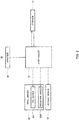
- FIG. 2 is a block diagram schematically showing the control configuration of the friction stir spot welding apparatus shown in FIG. 1 .
- the friction stir spot welding apparatus 50 includes a controller 51, a storage 31, and an inputter 32.
- the controller 51 controls respective structures (respective devices) constituting the friction stir spot welding apparatus 50. Specifically, the controller 51 reads and executes software, such as a basic program, stored in the storage to control the pin driver 531 and shoulder driver 532 of the tool driver 53 and the rotary driver 57.
- software such as a basic program
- the controller 51 may be constituted by a single controller 51 which performs centralized control or may be constituted by controllers 51 which cooperate to perform distributed control. Moreover, the controller 51 may be constituted by a microcomputer or may be constituted by an MPU, a PLC (Programmable Logic Controller), a logic circuit, or the like.
- a microcomputer or may be constituted by an MPU, a PLC (Programmable Logic Controller), a logic circuit, or the like.
- the storage 31 stores a basic program and various data and is constituted by a known memory, a storage apparatus such as a hard disk, or the like.
- the storage 31 does not have to be a single storage and may be constituted as storage apparatuses (for example, a random access memory and a hard disc drive).
- the controller 51 and the like are constituted by a microcomputer, at least part of the storage 31 may be constituted as an internal memory of the microcomputer or may be constituted as an independent memory.
- the storage 31 stores data, and the data may be read by a device other than the controller 51, and the controller 51 and the like may write data in the storage 31.
- the inputter 32 inputs, to the controller 51, various parameters regarding the control of the friction stir spot welding, other data, and the like.
- the inputter 32 is constituted by a known input device, such as a keyboard, a touch panel, or a button switch group.
- a known input device such as a keyboard, a touch panel, or a button switch group.
- at least data of welding conditions of the welded workpiece 60 can be input by the inputter 32.
- the controller 51 controls the tool driver 53 so as to reduce an absolute value of a tool average position Tx defined by Formula (I) below, where Ap denotes an area of the tip end surface of the pin 11, As denotes an area of the tip end surface of the shoulder 12, Pp denotes a press-in depth of the pin 11, and Ps denotes a press-in depth of the shoulder 12.
- Ap ⁇ Pp + As ⁇ Ps Tx
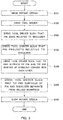
- FIG. 3 is a flow chart showing one example of the operation of the friction stir spot welding apparatus according to Embodiment 1.
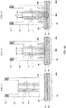
- FIGS. 4A and 4B are process diagrams schematically showing one example of respective steps of the friction stir spot welding performed by the friction stir spot welding apparatus shown in FIG. 1 .
- FIGS. 4A and 4B show an example in which a plate-shaped first workpiece 61 and a plate-shaped second workpiece 62 are used as the welded workpiece 60, and these workpieces 61 and 62 are laminated on each other and coupled to each other by spot welding.
- the first workpiece 61 and the second workpiece 62 may be made of fiber reinforced plastic (for example, carbon fiber reinforced plastic).
- the welded workpiece 60 is constituted by the plate-shaped first workpiece 61 and the plate-shaped second workpiece 62.
- the present embodiment is not limited to this, and the welded workpiece 60 (the first workpiece 61 and the second workpiece 62) may have any shape, and for example, may have a rectangular solid shape or a circular-arc shape.
- FIGS. 4A and 4B part of the double-acting friction welding apparatus is not shown.
- Arrows r indicate the rotational directions of the pin 11 and the shoulder 12
- block arrows F indicate directions of forces applied by the first workpiece 61 and the second workpiece 62.
- FIGS. 4A and 4B Although forces are applied to the first workpiece 61 and the second workpiece 62 from the backing structure 56, such forces are not shown in FIGS. 4A and 4B for convenience of explanation.
- the shoulder 12 is shown by cross hatching to clearly distinguish between the pin 11 and the clamp structure 54.
- a worker places the welded workpiece 60 on the supporting surface 56a of the backing structure 56.
- the worker manipulates the inputter 32 to input execution of welding of the welded workpiece 60 to the controller 51.
- a robot may place the welded workpiece 60 on the supporting surface 56a of the backing structure 56.
- the controller 51 drives the rotary driver 57 to rotate the pin 11 and the shoulder 12 at a preset and predetermined first rotational frequency (for example, 200 to 3,000 rpm) (Step S101; see Step (1) in FIG. 4A ).
- a preset and predetermined first rotational frequency for example, 200 to 3,000 rpm
- the controller 51 makes the pin 11, the shoulder 12, and the clamp structure 54 approach the welded workpiece 60 and brings the tip end surface 11a of the pin 11, the tip end surface 12a of the shoulder 12, and the tip end surface 54a of the clamp structure 54 (not shown in FIGS. 4A and 4B ) into contact with the front surface 60c of the welded workpiece 60 (Step S102; see Step (2) in FIG. 4A ).
- the controller 51 controls the tool driver 53 (shoulder driver 532) such that the pin 11, the shoulder 12, and the clamp structure 54 press the welded workpiece 60 by a preset and predetermined first pressing force (for example, a predetermined value within a range of 3 kN to 10 kN).
- a preset and predetermined first pressing force for example, a predetermined value within a range of 3 kN to 10 kN.
- first workpiece 61 and the second workpiece 62 are sandwiched by the clamp structure 54 and the backing structure 56, and the clamp structure 54 is biased toward the front surface 60c of the welded workpiece 60 by the contraction of the clamp driver 41 to generate clamping force.
- the front surface 60c of the welded workpiece 60 is subjected to "preheating." With this, a constituent material at a contact region of the first workpiece 61 is softened by heat generated by friction, and thus, a plastically flowing portion 60a is generated in the vicinity of the front surface 60c of the welded workpiece 60.
- the controller 51 drives the tool driver 53 such that the tip end surface 11a of the pin 11 sinks relative to the tip end surface 12a of the shoulder 12 (Step S103). At this time, the controller 51 may drive the tool driver 53 (pin driver 531) such that the pin 11 separates from the welded workpiece 60. Moreover, the controller 51 may drive the tool driver 53 (pin driver 531) such that the shoulder 12 is pressed in the welded workpiece 60.
- the controller 51 controls the pin driver 531 such that a tip end portion of the shoulder 12 reaches a preset and predetermined first position. Positional information of the tip end portion of the shoulder 12 is detected by a position detector (not shown) and output to the controller 51.
- a LVDT, an encoder, or the like may be used as the position detector.
- the first position may be set in advance by experiments or the like.
- a surface of the first workpiece 61 (the front surface 60c of the welded workpiece 60) is regarded as 0%, and a surface of the second workpiece 62 which surface contacts the supporting surface 56a is regarded as 100%
- the first position is set arbitrarily within a range of more than 0% and less than 100%.
- the first position is preferably located close to the surface of the second workpiece 62 which surface contacts the supporting surface 56a.
- the first position may be 25% or more, 50% or more, 75% or more, 80% or more, 90% or more, or 95% or more.
- a softened part of the welded workpiece 60 extends from the first workpiece 61 at the upper side to the second workpiece 62 at the lower side, and the volume of the plastically flowing portion 60a increases. Moreover, a softened material of the plastically flowing portion 60a is pushed away by the shoulder 12 to flow from a position right under the shoulder 12 to a position right under the pin 11. Therefore, the pin 11 retreats and moves upward relative to the shoulder 12 (see Step (3) in FIG. 4A ).
- the controller 51 drives the tool driver 53 (pin driver 531) such that the pin 11 advances toward the welded workpiece 60, or the controller 51 drives the tool driver 53 (shoulder driver 532) such that the shoulder 12 separates from the welded workpiece 60 (Step S104).
- the pin 11 gradually advances toward the first workpiece 61, and the shoulder 12 retreats from the first workpiece 61 (see Step (4) in FIG. 4B ).
- the softened part of the plastically flowing portion 60a flows from the position right under the pin 11 to the position right under the shoulder 12 (to a recess generated by press-in of the shoulder 12).
- the controller 51 may control the tool driver 53 such that the tip end surface 11a of the pin 11 is located at the first position. Moreover, the controller 51 may control the tool driver 53 such that the tip end surface 11a of the pin 11 reaches an inside of the second workpiece 62 or may control the tool driver 53 such that the tip end surface 11a of the pin 11 is located inside the first workpiece 61.
- controller 51 may control the tool driver 53 such that the tip end surface 11a of the pin 11 and the tip end surface 12a of the shoulder 12 coincide with each other. Furthermore, the controller 51 may control the tool driver 53 such that the tip end surface 11a of the pin 11 and the tip end surface 12a of the shoulder 12 reach the front surface 60c of the welded workpiece 60.
- the controller 51 when executing Steps S103 and S104, controls the tool driver 53 so as to reduce the absolute value of the tool average position Tx. Since specific control of reducing the absolute value of the tool average position Tx is disclosed in Japanese Laid-Open Patent Application Publication No. 2012-196682 in detail, an explanation thereof is omitted herein.
- the absolute value of the tool average position Tx may be reduced as much as possible from the viewpoint of practical use as long as satisfactory control can be performed.
- controller 51 controls the tool driver 53 such that the pressing force applied to the welded workpiece 60 from the pin 11 and the shoulder 12 in Step S104 is smaller than that in Step S103 and/or controls the rotary driver 57 such that the rotational frequencies of the pin 11 and the shoulder 12 in Step S104 are lower than those in Step S103.
- the fiber reinforced plastic of which the welded workpiece 60 is made can be prevented from being excessively heated, and the resin of the fiber reinforced plastic can be prevented from excessively flowing (being excessively softened). Therefore, it is possible to prevent a case where the plastically flowing resin (softened resin) flows outward beyond the tip end surface 12a of the shoulder 12, and this deteriorates appearance quality (mainly the generation of recesses and burrs at a welded portion).
- Step S105 the controller 51 controls the tool driver 53 such that the tip end surface 11a of the pin 11 and the tip end surface 12a of the shoulder 12 coincide with each other.
- the front surface 60c of the welded workpiece 60 is shaped, and a substantially flat surface where recesses are not practically generated is obtained (see Step (5) in FIG. 4B ).
- the controller 51 may control the rotary driver 57 such that the rotational frequencies of the pin 11 and the shoulder 12 in Step S105 are lower than those in Step S103. Moreover, the controller 51 may control the rotary driver 57 such that the rotational frequencies of the pin 11 and the shoulder 12 in Step S105 are lower than those in Step S104.
- the fiber reinforced plastic of which the welded workpiece 60 is made can be prevented from being excessively heated, and the resin of the fiber reinforced plastic can be prevented from excessively flowing (being excessively softened). Therefore, it is possible to prevent a case where the plastically flowing resin (softened resin) flows outward beyond the tip end surface 12a of the shoulder 12, and this deteriorates appearance quality (mainly the generation of recesses and burrs at the welded portion).
- controller 51 may control the tool driver 53 such that the pressing force applied to the welded workpiece 60 from the pin 11 and the shoulder 12 in Step S105 is larger than that in Step S104.
- voids void defects generated in the plastically flowing portion 60a of the welded workpiece 60 can be crushed, and the generation of the void defects in the welded workpiece 60 can be suppressed.
- the controller 51 controls the tool driver 53 (shoulder driver 532) such that the pin 11, the shoulder 12, and the clamp structure 54 separate from the welded workpiece 60 (Step S106).
- the controller 51 controls the rotary driver 57 to stop the rotation of the pin 11 and the shoulder 12 (Step S107) and terminates the friction stir spot welding (step of welding the welded workpiece 60) (see Step (6) in FIG. 4B ).
- the first workpiece 61 and the second workpiece 62 are coupled (welded) to each other by the welded portion 60b.
- the controller 51 controls the tool driver 53 such that the pressing force applied to the welded workpiece 60 from the pin 11 and the shoulder 12 in Step S104 is smaller than that in Step S103 and/or controls the rotary driver 57 such that the rotational frequencies of the pin 11 and the shoulder 12 in Step S104 are lower than those in Step S103.
- the fiber reinforced plastic of which the welded workpiece 60 is made can be prevented from being excessively heated, and the resin of the fiber reinforced plastic can be prevented from excessively flowing (being excessively softened). Therefore, it is possible to prevent a case where the plastically flowing resin (softened resin) flows outward beyond the tip end surface 12a of the shoulder 12, and this deteriorates appearance quality (mainly the generation of recesses and burrs at the welded portion).
- the controller 51 may control the rotary driver 57 such that the rotational frequencies of the pin 11 and the shoulder 12 in Step S105 are lower than those in Step S103. Moreover, the controller 51 may control the rotary driver 57 such that the rotational frequencies of the pin 11 and the shoulder 12 in Step S105 are lower than those in Step S104.
- the fiber reinforced plastic of which the welded workpiece 60 is made can be prevented from being excessively heated, and the resin of the fiber reinforced plastic can be prevented from excessively flowing (being excessively softened). Therefore, it is possible to prevent a case where the plastically flowing resin (softened resin) flows outward beyond the tip end surface 12a of the shoulder 12, and this deteriorates appearance quality (mainly the generation of recesses and burrs at the welded portion).
- the controller 51 may control the tool driver 53 such that the pressing force applied to the welded workpiece 60 from the pin 11 and the shoulder 12 in Step S105 is larger than that in Step S104.
- voids (void defects) generated in the plastically flowing portion 60a of the welded workpiece 60 can be crushed, and the generation of the void defects in the welded workpiece 60 can be suppressed.
- the controller 51 controls the tool driver 53 and the rotary driver 57 so as to reduce the absolute value of the tool average position Tx.
- the friction stir spot welding apparatus is configured such that in the friction stir spot welding apparatus according to Embodiment 1, the second workpiece is made of metal and includes a hole having an opening portion, and the controller changes a movement speed of the pin in the (C) in accordance with hardness of the fiber reinforced plastic located around a tip end portion of the pin.
- FIG. 5 is a schematic diagram showing a schematic configuration of the friction stir spot welding apparatus according to Embodiment 2.
- An upper-lower direction in FIG. 5 corresponds to an upper-lower direction of the friction stir spot welding apparatus.
- the friction stir spot welding apparatus 50 according to Embodiment 2 is the same in basic configuration as the friction stir spot welding apparatus 50 according to Embodiment 1 but is different from the friction stir spot welding apparatus 50 according to Embodiment 1 in that: a recess 56b is disposed at the supporting surface 56a of the backing structure 56; and the second workpiece 62 constituting the welded workpiece 60 is made of metal and includes a hole 62a having an opening portion.
- the recess 56b may have any shape as long as an opening area of the opening portion of the recess 56b is larger than an opening area of the hole 62a of the second workpiece 62.
- the recess 56b is formed in a semi-spherical shape.
- the present embodiment is not limited to this, and the recess 56b may be formed in a rectangular solid shape.
- the opening portion of the hole 62a may be formed in a circular shape or a polygonal shape.
- the area of the opening portion of the hole 62a can be suitably set depending on welding strength required for the welded workpiece 60.
- FIG. 6 is a flow chart showing one example of the operation of the friction stir spot welding apparatus according to Embodiment 2.
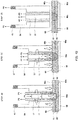
- FIGS. 7A and 7B are process diagrams showing one example of steps of the friction stir spot welding performed by the friction stir spot welding apparatus shown in FIG. 5 .
- FIGS. 7A and 7B show an example in which the plate-shaped first workpiece 61 and the plate-shaped second workpiece 62 are used as the welded workpiece 60, and these workpieces 61 and 62 are laminated on each other and coupled to each other by spot welding.
- the first workpiece 61 may be made of fiber reinforced plastic (for example, carbon fiber reinforced plastic).
- the second workpiece 62 may be made of metal (such as aluminum, steel, or titanium) or alloy (such as aluminum alloy).
- the welded workpiece 60 is constituted by the plate-shaped first workpiece 61 and the plate-shaped second workpiece 62.
- the present embodiment is not limited to this, and the welded workpiece 60 (the first workpiece 61 and the second workpiece 62) may have any shape, and for example, may have a rectangular solid shape or a circular-arc shape.
- FIGS. 7A and 7B part of the double-acting friction welding apparatus is not shown.
- Arrows r indicate the rotational directions of the pin 11 and the shoulder 12
- block arrows F indicate directions of forces applied by the first workpiece 61 and the second workpiece 62.
- FIGS. 7A and 7B Although forces are applied to the first workpiece 61 and the second workpiece 62 from the backing structure 56, such forces are not shown in FIGS. 7A and 7B for convenience of explanation.
- the shoulder 12 is shown by cross hatching to clearly distinguish between the pin 11 and the clamp structure 54.
- a worker places the welded workpiece 60 on the supporting surface 56a of the backing structure 56.
- the worker manipulates the inputter 32 to input execution of welding of the welded workpiece 60 to the controller 51.
- a robot may place the welded workpiece 60 on the supporting surface 56a of the backing structure 56.
- the controller 51 drives the rotary driver 57 to rotate the pin 11 and the shoulder 12 at a preset and predetermined second rotational frequency (for example, 200 to 3,000 rpm) (Step S201; see Step (1) in FIG. 7A ).
- a preset and predetermined second rotational frequency for example, 200 to 3,000 rpm
- the controller 51 makes the pin 11, the shoulder 12, and the clamp structure 54 approach the welded workpiece 60 and brings the tip end surface 11a of the pin 11, the tip end surface 12a of the shoulder 12, and the tip end surface 54a of the clamp structure 54 (not shown in FIGS. 7A and 7B ) into contact with the front surface 60c of the welded workpiece 60 (Step S202; see Step (2) in FIG. 7A ).
- the controller 51 controls the tool driver 53 (shoulder driver 532) such that the pin 11, the shoulder 12, and the clamp structure 54 press the welded workpiece 60 by a preset and predetermined second pressing force (for example, a predetermined value within a range of 3 kN to 10 kN).
- a preset and predetermined second pressing force for example, a predetermined value within a range of 3 kN to 10 kN.
- first workpiece 61 and the second workpiece 62 are sandwiched by the clamp structure 54 and the backing structure 56, and the clamp structure 54 is biased toward the front surface 60c of the welded workpiece 60 by the contraction of the clamp driver 41 to generate clamping force.
- the controller 51 drives the tool driver 53 such that the tip end surface 11a of the pin 11 sinks relative to the tip end surface 12a of the shoulder 12 (Step S203). At this time, the controller 51 may drive the tool driver 53 (pin driver 531) such that the pin 11 separates from the welded workpiece 60. Moreover, the controller 51 may drive the tool driver 53 (pin driver 531) such that the shoulder 12 is pressed in the welded workpiece 60.
- controller 51 controls the pin driver 531 such that the tip end portion of the shoulder 12 reaches a preset and predetermined second position.
- the second position may be set in advance by experiments or the like.
- the second position is set arbitrarily within a range of more than 0% and less than 100%.
- the second position is preferably located close to the surface of the first workpiece 61 which surface contacts the second workpiece 62.
- the second position may be 25% or more, 50% or more, 75% or more, 80% or more, 90% or more, or 95% or more.
- the controller 51 drives the tool driver 53 (pin driver 531) such that the pin 11 advances toward the welded workpiece 60, or the controller 51 drives the tool driver 53 (pin driver 531) such that the shoulder 12 separates from the welded workpiece 60 (Step S204).
- the pin 11 gradually enters into (is gradually pressed in) the first workpiece 61, and the shoulder 12 retreats from the first workpiece 61 (see Step (4) in FIG. 7B ).
- the softened part of the plastically flowing portion 60a flows from the position right under the pin 11 to the position right under the shoulder 12 (to a recess generated by press-in of the shoulder 12), is pushed away into the hole 62a of the second workpiece 62, and reaches the recess 56b of the backing structure 56.
- the pressing force applied to the welded workpiece 60 from the pin 11 and the shoulder 12, the rotational frequencies of the pin 11 and the shoulder 12, and a drive time of the tool driver 53 are obtained in advance by experiments such that the tool average position Tx satisfies Formula (1). Then, the obtained pressing force and the like are stored in the storage 31.
- controller 51 controls the tool driver 53 such that the pressing force applied to the welded workpiece 60 from the pin 11 and the shoulder 12 in Step S204 is smaller than that in Step S203 and/or controls the rotary driver 57 such that the rotational frequencies of the pin 11 and the shoulder 12 in Step S204 are lower than those in Step S203.
- the fiber reinforced plastic of which the welded workpiece 60 is made can be prevented from being excessively heated, and the resin of the fiber reinforced plastic can be prevented from excessively flowing (being excessively softened). Therefore, it is possible to prevent a case where the plastically flowing resin (softened resin) flows outward beyond the tip end surface 12a of the shoulder 12, and this deteriorates appearance quality (mainly the generation of recesses and burrs at the welded portion).
- controller 51 may change the movement speed of the pin 11 in accordance with the hardness of the fiber reinforced plastic located around the tip end portion of the pin 11.
- the movement speed of the pin 11 may be set in advance by experiments or the like.
- the controller 51 may control the tool driver 53 such that the movement speed of the pin 11 in Step S204 is higher than that in Step S203. Moreover, the controller 51 may change the movement speed of the pin 11 based on a table, a graph, or the like which is stored in the storage 31 in advance and shows a correlation among the hardness of the fiber reinforced plastic located around the tip end portion of the pin 11, the rotational frequencies of the pin 11 and the shoulder 12 in Step S203, and the pressing force applied to the welded workpiece 60 from the pin 11 and the shoulder 12.
- the controller 51 controls the tool driver 53 such that the tip end surface 11a of the pin 11 and the tip end surface 12a of the shoulder 12 coincide with each other (Step S205). With this, the front surface 60c of the welded workpiece 60 is shaped (see Step (5) in FIG. 7B ).
- the controller 51 may control the rotary driver 57 such that the rotational frequencies of the pin 11 and the shoulder 12 in Step S205 are lower than those in Step S203. Moreover, the controller 51 may control the rotary driver 57 such that the rotational frequencies of the pin 11 and the shoulder 12 in Step S205 are lower than those in Step S204.
- the fiber reinforced plastic of which the welded workpiece 60 is made can be prevented from being excessively heated, and the resin of the fiber reinforced plastic can be prevented from excessively flowing (being excessively softened). Therefore, it is possible to prevent a case where the plastically flowing resin (softened resin) flows outward beyond the tip end surface 12a of the shoulder 12, and this deteriorates appearance quality (mainly the generation of recesses and burrs at the welded portion).
- controller 51 may control the tool driver 53 such that the pressing force applied to the welded workpiece 60 from the pin 11 and the shoulder 12 in Step S205 is larger than that in Step S204.
- voids (void defects) generated in the plastically flowing portion 60a of the welded workpiece 60 can be crushed, and the generation of the void defects in the welded workpiece 60 can be suppressed.
- the controller 51 controls the tool driver 53 (shoulder driver 532) such that the pin 11, the shoulder 12, and the clamp structure 54 separate from the welded workpiece 60 (Step S206).
- the controller 51 controls the rotary driver 57 to stop the rotation of the pin 11 and the shoulder 12 (Step S207) and terminates the friction stir spot welding (step of welding the welded workpiece 60) (see Step (6) in FIG. 7B ).
- the friction stir spot welding apparatus 50 according to Embodiment 2 configured as above can obtain operational advantages similar to the operational advantages of the friction stir spot welding apparatus 50 according to Embodiment 1.
- the recess 56b is formed on the supporting surface 56a of the backing structure 56, and the hole 62a is formed on the second workpiece 62.
- the first workpiece 61 and the second workpiece 62 are welded to each other in such a manner that the plastically flowing portion 60a is pushed out to the hole 62a to reach the recess 56b. Therefore, even when the second workpiece 62 is made of a material (such as steel or titanium) that is difficult to be softened, the first workpiece 61 and the second workpiece 62 can be welded to each other.
- FIG. 8 is a schematic diagram showing a schematic configuration of the friction stir spot welding apparatus according to Modified Example 1 of Embodiment 2.
- An upper-lower direction in FIG. 8 corresponds to an upper-lower direction of the friction stir spot welding apparatus.
- the friction stir spot welding apparatus 50 according to Modified Example 1 is the same in basic configuration as the friction stir spot welding apparatus 50 according to Embodiment 2 but is different from the friction stir spot welding apparatus 50 according to Embodiment 2 regarding the shape of the hole 62a of the second workpiece 62 constituting the welded workpiece 60.
- the hole 62a is formed such that an area of an opening of a surface of the second workpiece 62 which surface contacts the supporting surface 56a of the backing structure 56 is larger than an area of an opening of a surface of the second workpiece 62 which surface contacts the first workpiece 61.
- the welded portion 60b of the welded workpiece 60 can obtain an anchor effect. Therefore, in the friction stir spot welding apparatus 50 of Modified Example 1, the recess 56b does not have to be disposed on the supporting surface 56a of the backing structure 56.
- the hole 62a may have any shape as long as the area of the opening of the surface of the second workpiece 62 which surface contacts the supporting surface 56a of the backing structure 56 is larger than the area of the opening of the surface of the second workpiece 62 which surface contacts the first workpiece 61.
- the hole 62a may be formed such that the shape of a section thereof along a normal direction of a main surface of the second workpiece 62 is a tapered shape as shown in FIG. 8 .
- the hole 62a may be formed such that the shape of a section thereof along the normal direction of the main surface of the second workpiece 62 is a step shape.
- the friction stir spot welding apparatus 50 according to Modified Example 1 configured as above has operational advantages similar to the friction stir spot welding apparatus 50 according to Embodiment 2.
- the friction stir spot welding apparatus and the friction stir spot welding method according to the present disclosure are useful to realize satisfactory welding quality of a welded workpiece including fiber reinforced plastic.
Landscapes
- Engineering & Computer Science (AREA)
- Mechanical Engineering (AREA)
- Pressure Welding/Diffusion-Bonding (AREA)
- Lining Or Joining Of Plastics Or The Like (AREA)
Applications Claiming Priority (2)
| Application Number | Priority Date | Filing Date | Title |
|---|---|---|---|
| JP2019000670A JP7216551B2 (ja) | 2019-01-07 | 2019-01-07 | 摩擦攪拌点接合装置及び摩擦攪拌点接合方法 |
| PCT/JP2020/000084 WO2020145243A1 (ja) | 2019-01-07 | 2020-01-06 | 摩擦攪拌点接合装置及び摩擦攪拌点接合方法 |
Publications (3)
| Publication Number | Publication Date |
|---|---|
| EP3909714A1 true EP3909714A1 (de) | 2021-11-17 |
| EP3909714A4 EP3909714A4 (de) | 2022-11-09 |
| EP3909714B1 EP3909714B1 (de) | 2025-11-12 |
Family
ID=71521639
Family Applications (1)
| Application Number | Title | Priority Date | Filing Date |
|---|---|---|---|
| EP20738293.8A Active EP3909714B1 (de) | 2019-01-07 | 2020-01-06 | Reibrührpunktschweissvorrichtung und reibrührpunktschweissverfahren |
Country Status (6)
| Country | Link |
|---|---|
| US (1) | US11534981B2 (de) |
| EP (1) | EP3909714B1 (de) |
| JP (1) | JP7216551B2 (de) |
| KR (1) | KR102553682B1 (de) |
| CN (1) | CN113226621B (de) |
| WO (1) | WO2020145243A1 (de) |
Cited By (1)
| Publication number | Priority date | Publication date | Assignee | Title |
|---|---|---|---|---|
| AT525908A4 (de) * | 2022-10-24 | 2023-09-15 | Royos Joining Solutions Gmbh | Rührschweißvorrichtung zur Herstellung einer Schweißverbindung |
Families Citing this family (17)
| Publication number | Priority date | Publication date | Assignee | Title |
|---|---|---|---|---|
| EP3680051B1 (de) * | 2017-09-04 | 2023-08-16 | Kawasaki Jukogyo Kabushiki Kaisha | Verfahren zum betrieb einer doppelt wirkenden reibrührschweissvorrichtung und doppelt wirkende reibrührschweissvorrichtung |
| CN112770863B (zh) * | 2018-10-11 | 2022-07-29 | 川崎重工业株式会社 | 摩擦搅拌接合装置、其运转方法以及接头构造 |
| US12202066B2 (en) * | 2020-05-29 | 2025-01-21 | Kawasaki Jukogyo Kabushiki Kaisha | Friction stir spot welding apparatus and joint structure |
| JP7596088B2 (ja) * | 2020-07-09 | 2024-12-09 | 株式会社Uacj | 摩擦攪拌点接合装置及び摩擦攪拌点接合方法 |
| WO2022045171A1 (ja) * | 2020-08-25 | 2022-03-03 | 川崎重工業株式会社 | 摩擦攪拌点接合方法及びこれを用いた接合体 |
| JP7445007B2 (ja) * | 2020-09-11 | 2024-03-06 | 川崎重工業株式会社 | 摩擦攪拌点接合方法及びこれを用いた接合体 |
| TWI739681B (zh) * | 2020-11-27 | 2021-09-11 | 財團法人金屬工業研究發展中心 | 摩擦攪拌銲接壓持治具系統 |
| WO2022145382A1 (ja) * | 2020-12-28 | 2022-07-07 | 川崎重工業株式会社 | 接合方法、接合体及び接合装置 |
| JP7524096B2 (ja) * | 2021-02-08 | 2024-07-29 | 川崎重工業株式会社 | 摩擦撹拌接合装置の制御方法および摩擦撹拌接合装置 |
| JP7685208B2 (ja) * | 2021-03-25 | 2025-05-29 | 地方独立行政法人鳥取県産業技術センター | 金属樹脂接合装置 |
| JP7524122B2 (ja) * | 2021-03-30 | 2024-07-29 | 川崎重工業株式会社 | 接合構造体および接合方法 |
| AT525198B1 (de) * | 2021-06-29 | 2025-05-15 | Stirtec Gmbh | Verfahren zum Verbinden übereinander angeordneter Bauteile, Verbundbauteil sowie Vorrichtung zur Durchführung eines entsprechenden Verfahrens |
| KR102877383B1 (ko) * | 2021-08-31 | 2025-10-27 | 제이에프이 스틸 가부시키가이샤 | 마찰 교반점 접합 조인트 및 그의 제조 방법, 그리고, 마찰 교반점 접합 방법 |
| JP7694344B2 (ja) * | 2021-11-05 | 2025-06-18 | 日本軽金属株式会社 | 回転ツール、接合装置及び接合方法 |
| JP7600961B2 (ja) * | 2021-11-05 | 2024-12-17 | 日本軽金属株式会社 | 回転ツール、接合装置及び接合方法 |
| JP2023152110A (ja) * | 2022-04-01 | 2023-10-16 | 川崎重工業株式会社 | 摩擦撹拌接合装置及びそのメンテナンス方法 |
| EP4699729A1 (de) * | 2024-08-21 | 2026-02-25 | Helmholtz-Zentrum hereon GmbH | Verfahren und vorrichtung zum reibrührpunktschweissen |
Family Cites Families (11)
| Publication number | Priority date | Publication date | Assignee | Title |
|---|---|---|---|---|
| JPS6020501B2 (ja) | 1979-12-18 | 1985-05-22 | 株式会社クラレ | 繊維製品用糊付け剤 |
| JPS6020501U (ja) | 1983-07-15 | 1985-02-13 | 森光 敦子 | ミニ蚊取り線香 |
| DE19955737B4 (de) * | 1999-11-18 | 2005-11-10 | Gkss-Forschungszentrum Geesthacht Gmbh | Verfahren und Vorrichtung zum Verbinden von wenigstens zwei aneinanderliegenden Werkstücken nach der Methode des Reibrührschweißens |
| JP2004255441A (ja) | 2003-02-27 | 2004-09-16 | Isuzu Motors Ltd | 摩擦撹拌装置及び摩擦撹拌方法 |
| JP4886277B2 (ja) * | 2005-11-17 | 2012-02-29 | 日野自動車株式会社 | 材料の接合方法 |
| JP5588385B2 (ja) | 2011-03-18 | 2014-09-10 | 川崎重工業株式会社 | 摩擦攪拌点接合装置および摩擦攪拌点接合方法 |
| JP5971273B2 (ja) | 2014-03-26 | 2016-08-17 | トヨタ自動車株式会社 | 接合方法 |
| JP6020501B2 (ja) | 2014-03-27 | 2016-11-02 | トヨタ自動車株式会社 | 接合方法 |
| KR101854794B1 (ko) * | 2014-10-23 | 2018-05-08 | 카와사키 주코교 카부시키 카이샤 | 마찰 교반 점 접합 장치 및 마찰 교반 점 접합 방법 |
| EP3235585B1 (de) * | 2014-12-15 | 2021-01-20 | Kawasaki Jukogyo Kabushiki Kaisha | Reibrührpunktschweissvorrichtung und reibrührpunktschweissverfahren |
| WO2017047574A1 (ja) | 2015-09-14 | 2017-03-23 | 川崎重工業株式会社 | 摩擦攪拌点接合装置及び摩擦攪拌点接合方法 |
-
2019
- 2019-01-07 JP JP2019000670A patent/JP7216551B2/ja active Active
-
2020
- 2020-01-06 EP EP20738293.8A patent/EP3909714B1/de active Active
- 2020-01-06 KR KR1020217023768A patent/KR102553682B1/ko active Active
- 2020-01-06 CN CN202080008253.7A patent/CN113226621B/zh active Active
- 2020-01-06 WO PCT/JP2020/000084 patent/WO2020145243A1/ja not_active Ceased
-
2021
- 2021-07-07 US US17/368,826 patent/US11534981B2/en active Active
Cited By (3)
| Publication number | Priority date | Publication date | Assignee | Title |
|---|---|---|---|---|
| AT525908A4 (de) * | 2022-10-24 | 2023-09-15 | Royos Joining Solutions Gmbh | Rührschweißvorrichtung zur Herstellung einer Schweißverbindung |
| AT525908B1 (de) * | 2022-10-24 | 2023-09-15 | Royos Joining Solutions Gmbh | Rührschweißvorrichtung zur Herstellung einer Schweißverbindung |
| WO2024086863A1 (de) | 2022-10-24 | 2024-05-02 | Royos Joining Solutions Gmbh | RÜHRSCHWEIßVORRICHTUNG ZUR HERSTELLUNG EINER SCHWEIßVERBINDUNG |
Also Published As
| Publication number | Publication date |
|---|---|
| CN113226621B (zh) | 2023-10-24 |
| KR102553682B1 (ko) | 2023-07-10 |
| KR20210105989A (ko) | 2021-08-27 |
| US20210331421A1 (en) | 2021-10-28 |
| WO2020145243A1 (ja) | 2020-07-16 |
| EP3909714A4 (de) | 2022-11-09 |
| US11534981B2 (en) | 2022-12-27 |
| EP3909714B1 (de) | 2025-11-12 |
| JP2020108902A (ja) | 2020-07-16 |
| JP7216551B2 (ja) | 2023-02-01 |
| CN113226621A (zh) | 2021-08-06 |
Similar Documents
| Publication | Publication Date | Title |
|---|---|---|
| EP3909714B1 (de) | Reibrührpunktschweissvorrichtung und reibrührpunktschweissverfahren | |
| EP3932606A1 (de) | Verbindungsvorrichtung für einen reibrührpunkt, verbundener gegenstand mit einem verbundenen reibrührpunkt und schulterteil | |
| US10293431B2 (en) | Friction stir spot welding apparatus and friction stir spot welding method | |
| EP3903986B1 (de) | Vorrichtung zum reibrührpunktschweissen und betriebsverfahren dafür | |
| EP3450080B1 (de) | Punktschweissorrichtung und punktschweissverfahren | |
| EP4159356B1 (de) | Reibrührpunktschweissvorrichtung zum verbinden eines zu verbindenden gegenstands durch erweichen des gegenstands mittels reibungswärme, und verfahren zum verbinden eines zu verbindenden gegenstands durch erweichen des gegenstands mittels reibungswärme | |
| US20250312865A1 (en) | Friction stir spot welder and friction stir spot welding method | |
| US12496655B2 (en) | Friction stir joining device, method of operating the same and joint structure | |
| KR102759552B1 (ko) | 접합 시스템 및 그 운전 방법 | |
| KR102747977B1 (ko) | 마찰교반 점접합 장치 및 그 운전 방법 | |
| WO2020218444A1 (ja) | 摩擦攪拌点接合装置及びその運転方法 | |
| WO2020032141A1 (ja) | 摩擦攪拌接合装置及びその運転方法 | |
| JP4507743B2 (ja) | 摩擦接合方法およびその装置 |
Legal Events
| Date | Code | Title | Description |
|---|---|---|---|
| STAA | Information on the status of an ep patent application or granted ep patent |
Free format text: STATUS: THE INTERNATIONAL PUBLICATION HAS BEEN MADE |
|
| PUAI | Public reference made under article 153(3) epc to a published international application that has entered the european phase |
Free format text: ORIGINAL CODE: 0009012 |
|
| STAA | Information on the status of an ep patent application or granted ep patent |
Free format text: STATUS: REQUEST FOR EXAMINATION WAS MADE |
|
| 17P | Request for examination filed |
Effective date: 20210708 |
|
| AK | Designated contracting states |
Kind code of ref document: A1 Designated state(s): AL AT BE BG CH CY CZ DE DK EE ES FI FR GB GR HR HU IE IS IT LI LT LU LV MC MK MT NL NO PL PT RO RS SE SI SK SM TR |
|
| DAV | Request for validation of the european patent (deleted) | ||
| DAX | Request for extension of the european patent (deleted) | ||
| A4 | Supplementary search report drawn up and despatched |
Effective date: 20221010 |
|
| RIC1 | Information provided on ipc code assigned before grant |
Ipc: B23K 103/00 20060101ALN20221004BHEP Ipc: B23K 103/16 20060101ALN20221004BHEP Ipc: B23K 103/18 20060101ALI20221004BHEP Ipc: B29C 65/64 20060101ALI20221004BHEP Ipc: B23K 20/22 20060101ALI20221004BHEP Ipc: B29C 65/06 20060101ALI20221004BHEP Ipc: B23K 20/12 20060101AFI20221004BHEP |
|
| GRAP | Despatch of communication of intention to grant a patent |
Free format text: ORIGINAL CODE: EPIDOSNIGR1 |
|
| STAA | Information on the status of an ep patent application or granted ep patent |
Free format text: STATUS: GRANT OF PATENT IS INTENDED |
|
| RIC1 | Information provided on ipc code assigned before grant |
Ipc: B23K 20/12 20060101AFI20250710BHEP Ipc: B29C 65/06 20060101ALI20250710BHEP Ipc: B23K 20/22 20060101ALI20250710BHEP Ipc: B29C 65/64 20060101ALI20250710BHEP Ipc: B23K 103/18 20060101ALI20250710BHEP Ipc: B23K 103/16 20060101ALN20250710BHEP Ipc: B23K 103/00 20060101ALN20250710BHEP |
|
| INTG | Intention to grant announced |
Effective date: 20250804 |
|
| GRAS | Grant fee paid |
Free format text: ORIGINAL CODE: EPIDOSNIGR3 |
|
| GRAA | (expected) grant |
Free format text: ORIGINAL CODE: 0009210 |
|
| STAA | Information on the status of an ep patent application or granted ep patent |
Free format text: STATUS: THE PATENT HAS BEEN GRANTED |
|
| AK | Designated contracting states |
Kind code of ref document: B1 Designated state(s): AL AT BE BG CH CY CZ DE DK EE ES FI FR GB GR HR HU IE IS IT LI LT LU LV MC MK MT NL NO PL PT RO RS SE SI SK SM TR |
|
| REG | Reference to a national code |
Ref country code: CH Ref legal event code: F10 Free format text: ST27 STATUS EVENT CODE: U-0-0-F10-F00 (AS PROVIDED BY THE NATIONAL OFFICE) Effective date: 20251112 Ref country code: GB Ref legal event code: FG4D |
|
| REG | Reference to a national code |
Ref country code: IE Ref legal event code: FG4D |
|
| REG | Reference to a national code |
Ref country code: DE Ref legal event code: R096 Ref document number: 602020062082 Country of ref document: DE |
|
| PGFP | Annual fee paid to national office [announced via postgrant information from national office to epo] |
Ref country code: FR Payment date: 20251223 Year of fee payment: 7 |
|
| REG | Reference to a national code |
Ref country code: NL Ref legal event code: MP Effective date: 20251112 |
|
| PGFP | Annual fee paid to national office [announced via postgrant information from national office to epo] |
Ref country code: GB Payment date: 20260119 Year of fee payment: 7 |
|
| PG25 | Lapsed in a contracting state [announced via postgrant information from national office to epo] |
Ref country code: ES Free format text: LAPSE BECAUSE OF FAILURE TO SUBMIT A TRANSLATION OF THE DESCRIPTION OR TO PAY THE FEE WITHIN THE PRESCRIBED TIME-LIMIT Effective date: 20251112 |
|
| REG | Reference to a national code |
Ref country code: LT Ref legal event code: MG9D |
|
| PG25 | Lapsed in a contracting state [announced via postgrant information from national office to epo] |
Ref country code: NO Free format text: LAPSE BECAUSE OF FAILURE TO SUBMIT A TRANSLATION OF THE DESCRIPTION OR TO PAY THE FEE WITHIN THE PRESCRIBED TIME-LIMIT Effective date: 20260212 |
|
| PGFP | Annual fee paid to national office [announced via postgrant information from national office to epo] |
Ref country code: DE Payment date: 20260119 Year of fee payment: 7 |
|
| PG25 | Lapsed in a contracting state [announced via postgrant information from national office to epo] |
Ref country code: AT Free format text: LAPSE BECAUSE OF FAILURE TO SUBMIT A TRANSLATION OF THE DESCRIPTION OR TO PAY THE FEE WITHIN THE PRESCRIBED TIME-LIMIT Effective date: 20251112 Ref country code: FI Free format text: LAPSE BECAUSE OF FAILURE TO SUBMIT A TRANSLATION OF THE DESCRIPTION OR TO PAY THE FEE WITHIN THE PRESCRIBED TIME-LIMIT Effective date: 20251112 Ref country code: HR Free format text: LAPSE BECAUSE OF FAILURE TO SUBMIT A TRANSLATION OF THE DESCRIPTION OR TO PAY THE FEE WITHIN THE PRESCRIBED TIME-LIMIT Effective date: 20251112 |
|
| PGFP | Annual fee paid to national office [announced via postgrant information from national office to epo] |
Ref country code: IT Payment date: 20251223 Year of fee payment: 7 |
|
| REG | Reference to a national code |
Ref country code: AT Ref legal event code: MK05 Ref document number: 1856363 Country of ref document: AT Kind code of ref document: T Effective date: 20251112 |
|
| PG25 | Lapsed in a contracting state [announced via postgrant information from national office to epo] |
Ref country code: NL Free format text: LAPSE BECAUSE OF FAILURE TO SUBMIT A TRANSLATION OF THE DESCRIPTION OR TO PAY THE FEE WITHIN THE PRESCRIBED TIME-LIMIT Effective date: 20251112 |
|
| PG25 | Lapsed in a contracting state [announced via postgrant information from national office to epo] |
Ref country code: RS Free format text: LAPSE BECAUSE OF FAILURE TO SUBMIT A TRANSLATION OF THE DESCRIPTION OR TO PAY THE FEE WITHIN THE PRESCRIBED TIME-LIMIT Effective date: 20260212 |
|
| PG25 | Lapsed in a contracting state [announced via postgrant information from national office to epo] |
Ref country code: IS Free format text: LAPSE BECAUSE OF FAILURE TO SUBMIT A TRANSLATION OF THE DESCRIPTION OR TO PAY THE FEE WITHIN THE PRESCRIBED TIME-LIMIT Effective date: 20260312 |
|
| PG25 | Lapsed in a contracting state [announced via postgrant information from national office to epo] |
Ref country code: PT Free format text: LAPSE BECAUSE OF FAILURE TO SUBMIT A TRANSLATION OF THE DESCRIPTION OR TO PAY THE FEE WITHIN THE PRESCRIBED TIME-LIMIT Effective date: 20260312 |
|
| PG25 | Lapsed in a contracting state [announced via postgrant information from national office to epo] |
Ref country code: PL Free format text: LAPSE BECAUSE OF FAILURE TO SUBMIT A TRANSLATION OF THE DESCRIPTION OR TO PAY THE FEE WITHIN THE PRESCRIBED TIME-LIMIT Effective date: 20251112 |
|
| PG25 | Lapsed in a contracting state [announced via postgrant information from national office to epo] |
Ref country code: LV Free format text: LAPSE BECAUSE OF FAILURE TO SUBMIT A TRANSLATION OF THE DESCRIPTION OR TO PAY THE FEE WITHIN THE PRESCRIBED TIME-LIMIT Effective date: 20251112 |