EP3909735B1 - Verfahren zum aufbereiten von betongranulat durch co2-behandlung - Google Patents
Verfahren zum aufbereiten von betongranulat durch co2-behandlung Download PDFInfo
- Publication number
- EP3909735B1 EP3909735B1 EP20174964.5A EP20174964A EP3909735B1 EP 3909735 B1 EP3909735 B1 EP 3909735B1 EP 20174964 A EP20174964 A EP 20174964A EP 3909735 B1 EP3909735 B1 EP 3909735B1
- Authority
- EP
- European Patent Office
- Prior art keywords
- container
- concrete
- gas
- granulate
- concrete granulate
- Prior art date
- Legal status (The legal status is an assumption and is not a legal conclusion. Google has not performed a legal analysis and makes no representation as to the accuracy of the status listed.)
- Active
Links
Images

Classifications
-
- C—CHEMISTRY; METALLURGY
- C04—CEMENTS; CONCRETE; ARTIFICIAL STONE; CERAMICS; REFRACTORIES
- C04B—LIME, MAGNESIA; SLAG; CEMENTS; COMPOSITIONS THEREOF, e.g. MORTARS, CONCRETE OR LIKE BUILDING MATERIALS; ARTIFICIAL STONE; CERAMICS; REFRACTORIES; TREATMENT OF NATURAL STONE
- C04B18/00—Use of agglomerated or waste materials or refuse as fillers for mortars, concrete or artificial stone; Treatment of agglomerated or waste materials or refuse, specially adapted to enhance their filling properties in mortars, concrete or artificial stone
- C04B18/04—Waste materials; Refuse
- C04B18/16—Waste materials; Refuse from building or ceramic industry
- C04B18/167—Recycled materials, i.e. waste materials reused in the production of the same materials
-
- B—PERFORMING OPERATIONS; TRANSPORTING
- B01—PHYSICAL OR CHEMICAL PROCESSES OR APPARATUS IN GENERAL
- B01D—SEPARATION
- B01D53/00—Separation of gases or vapours; Recovering vapours of volatile solvents from gases; Chemical or biological purification of waste gases, e.g. engine exhaust gases, smoke, fumes, flue gases, aerosols
- B01D53/34—Chemical or biological purification of waste gases
- B01D53/346—Controlling the process
-
- B—PERFORMING OPERATIONS; TRANSPORTING
- B01—PHYSICAL OR CHEMICAL PROCESSES OR APPARATUS IN GENERAL
- B01D—SEPARATION
- B01D53/00—Separation of gases or vapours; Recovering vapours of volatile solvents from gases; Chemical or biological purification of waste gases, e.g. engine exhaust gases, smoke, fumes, flue gases, aerosols
- B01D53/34—Chemical or biological purification of waste gases
- B01D53/46—Removing components of defined structure
- B01D53/62—Carbon oxides
-
- B—PERFORMING OPERATIONS; TRANSPORTING
- B01—PHYSICAL OR CHEMICAL PROCESSES OR APPARATUS IN GENERAL
- B01D—SEPARATION
- B01D53/00—Separation of gases or vapours; Recovering vapours of volatile solvents from gases; Chemical or biological purification of waste gases, e.g. engine exhaust gases, smoke, fumes, flue gases, aerosols
- B01D53/34—Chemical or biological purification of waste gases
- B01D53/74—General processes for purification of waste gases; Apparatus or devices specially adapted therefor
- B01D53/81—Solid phase processes
-
- B—PERFORMING OPERATIONS; TRANSPORTING
- B28—WORKING CEMENT, CLAY, OR STONE
- B28B—SHAPING CLAY OR OTHER CERAMIC COMPOSITIONS; SHAPING SLAG; SHAPING MIXTURES CONTAINING CEMENTITIOUS MATERIAL, e.g. PLASTER
- B28B11/00—Apparatus or processes for treating or working the shaped or preshaped articles
- B28B11/24—Apparatus or processes for treating or working the shaped or preshaped articles for curing, setting or hardening
- B28B11/245—Curing concrete articles
-
- B—PERFORMING OPERATIONS; TRANSPORTING
- B28—WORKING CEMENT, CLAY, OR STONE
- B28C—PREPARING CLAY; PRODUCING MIXTURES CONTAINING CLAY OR CEMENTITIOUS MATERIAL, e.g. PLASTER
- B28C7/00—Controlling the operation of apparatus for producing mixtures of clay or cement with other substances; Supplying or proportioning the ingredients for mixing clay or cement with other substances; Discharging the mixture
- B28C7/0007—Pretreatment of the ingredients, e.g. by heating, sorting, grading, drying, disintegrating; Preventing generation of dust
-
- C—CHEMISTRY; METALLURGY
- C04—CEMENTS; CONCRETE; ARTIFICIAL STONE; CERAMICS; REFRACTORIES
- C04B—LIME, MAGNESIA; SLAG; CEMENTS; COMPOSITIONS THEREOF, e.g. MORTARS, CONCRETE OR LIKE BUILDING MATERIALS; ARTIFICIAL STONE; CERAMICS; REFRACTORIES; TREATMENT OF NATURAL STONE
- C04B20/00—Use of materials as fillers for mortars, concrete or artificial stone according to more than one of groups C04B14/00 - C04B18/00 and characterised by shape or grain distribution; Treatment of materials according to more than one of the groups C04B14/00 - C04B18/00 specially adapted to enhance their filling properties in mortars, concrete or artificial stone; Expanding or defibrillating materials
- C04B20/02—Treatment
- C04B20/023—Chemical treatment
-
- C—CHEMISTRY; METALLURGY
- C04—CEMENTS; CONCRETE; ARTIFICIAL STONE; CERAMICS; REFRACTORIES
- C04B—LIME, MAGNESIA; SLAG; CEMENTS; COMPOSITIONS THEREOF, e.g. MORTARS, CONCRETE OR LIKE BUILDING MATERIALS; ARTIFICIAL STONE; CERAMICS; REFRACTORIES; TREATMENT OF NATURAL STONE
- C04B40/00—Processes, in general, for influencing or modifying the properties of mortars, concrete or artificial stone compositions, e.g. their setting or hardening ability
- C04B40/02—Selection of the hardening environment
- C04B40/0231—Carbon dioxide hardening
-
- C—CHEMISTRY; METALLURGY
- C04—CEMENTS; CONCRETE; ARTIFICIAL STONE; CERAMICS; REFRACTORIES
- C04B—LIME, MAGNESIA; SLAG; CEMENTS; COMPOSITIONS THEREOF, e.g. MORTARS, CONCRETE OR LIKE BUILDING MATERIALS; ARTIFICIAL STONE; CERAMICS; REFRACTORIES; TREATMENT OF NATURAL STONE
- C04B40/00—Processes, in general, for influencing or modifying the properties of mortars, concrete or artificial stone compositions, e.g. their setting or hardening ability
- C04B40/02—Selection of the hardening environment
- C04B40/0231—Carbon dioxide hardening
- C04B40/0236—Carbon dioxide post-treatment of already hardened material
-
- B—PERFORMING OPERATIONS; TRANSPORTING
- B01—PHYSICAL OR CHEMICAL PROCESSES OR APPARATUS IN GENERAL
- B01D—SEPARATION
- B01D2257/00—Components to be removed
- B01D2257/50—Carbon oxides
- B01D2257/504—Carbon dioxide
-
- Y—GENERAL TAGGING OF NEW TECHNOLOGICAL DEVELOPMENTS; GENERAL TAGGING OF CROSS-SECTIONAL TECHNOLOGIES SPANNING OVER SEVERAL SECTIONS OF THE IPC; TECHNICAL SUBJECTS COVERED BY FORMER USPC CROSS-REFERENCE ART COLLECTIONS [XRACs] AND DIGESTS
- Y02—TECHNOLOGIES OR APPLICATIONS FOR MITIGATION OR ADAPTATION AGAINST CLIMATE CHANGE
- Y02P—CLIMATE CHANGE MITIGATION TECHNOLOGIES IN THE PRODUCTION OR PROCESSING OF GOODS
- Y02P40/00—Technologies relating to the processing of minerals
- Y02P40/10—Production of cement, e.g. improving or optimising the production methods; Cement grinding
- Y02P40/18—Carbon capture and storage [CCS]
-
- Y—GENERAL TAGGING OF NEW TECHNOLOGICAL DEVELOPMENTS; GENERAL TAGGING OF CROSS-SECTIONAL TECHNOLOGIES SPANNING OVER SEVERAL SECTIONS OF THE IPC; TECHNICAL SUBJECTS COVERED BY FORMER USPC CROSS-REFERENCE ART COLLECTIONS [XRACs] AND DIGESTS
- Y02—TECHNOLOGIES OR APPLICATIONS FOR MITIGATION OR ADAPTATION AGAINST CLIMATE CHANGE
- Y02W—CLIMATE CHANGE MITIGATION TECHNOLOGIES RELATED TO WASTEWATER TREATMENT OR WASTE MANAGEMENT
- Y02W30/00—Technologies for solid waste management
- Y02W30/50—Reuse, recycling or recovery technologies
- Y02W30/91—Use of waste materials as fillers for mortars or concrete
Definitions
- the present invention relates to a method for processing concrete granulate for the subsequent recycling of the concrete granulate.
- the present invention relates in particular to a method for enriching concrete granulate with CO2.
- the cement content in conventionally recycled concrete is usually increased by 10% in order to obtain recycled concrete of a similar quality to that of the primary concrete.
- the concrete granulate obtained from demolition concrete can be used loose in an unbound state, e.g. as road building material.
- its use is very limited because the concrete contains toxic metals due to its production process, which can be dissolved by rainwater, particularly in the loose (unbound) state of the concrete granulate known from the state of the art, and can thus contaminate the groundwater.
- today's concrete recycling produces at best inferior gravel substitutes; however, this recycling does not reduce the greenhouse gas emissions of the concrete, nor can the concrete granulate be used loose without concern.
- the object of the invention is to provide an improved method for processing of concrete granulate for the subsequent recycling of the concrete granulate.
- the above-mentioned problems of known recycling processes are at least partially eliminated.
- the concrete granulate can be treated with carbon dioxide (hereinafter abbreviated as CO2).
- CO2 carbon dioxide
- the enriched concrete can have a higher compressive strength with essentially the same slump. The latter is a parameter for the consistency of fresh concrete.
- the same compressive strength can be achieved compared to the reference concrete with an unchanged composition.
- the enriched concrete with a correspondingly reduced cement content (e.g. test concrete 3) therefore has significantly reduced greenhouse gas emissions.
- the emissions from concrete production can be reduced by around 8.5%.
- existing CO2 emissions can be bound to the concrete granulate during the process and thus reduced.
- emissions can be reduced by an average of a further 4%.
- the technology can thus reduce the CO2 emissions from the production of recycled concrete by around 12.5%.
- the enriched concrete has a higher carbonation resistance.
- the carbonation resistance is a decisive factor for the corrosion of reinforcement cast in the concrete and damage that occurs in concrete construction.
- the enrichment of the concrete granulate with CO2 can lead to the toxic metals mentioned above being better bound and their unwanted escape into the environment can be significantly reduced. This expands the application possibilities of the loose concrete granulate.
- a sophisticated method for processing, in particular for enriching with CO2, concrete granulate for subsequent recycling comprises the following method steps: Filling a container that is at least partially gas-tight with concrete granulate. Supplying a volume flow of gas comprising CO2 depending on a degree of CO2 absorption by the concrete granulate in the container determined by at least one sensor. The gas can be supplied continuously or discontinuously. Determining whether a predetermined CO2 saturation of the concrete granulate between 5 kg CO2 per 1000 kg and 15 kg CO2 per 1000 kg has been reached, and otherwise continuing the previous method step regarding the supply of gas. If the concrete granulate is not yet saturated with CO2, the gas can be supplied continuously or discontinuously, depending on the application, until this is achieved.
- the method also includes removing the concrete granulate enriched with CO2 from the container. After the concrete granulate has been removed, it can be A further process step can be used to produce recycled (enriched) concrete comprising the concrete granulate enriched with CO2.
- the concrete granulate enriched with CO2 can be processed into concrete with cement, water, sand and gravel.
- CO2 absorption by the concrete granulate means that the CO2 diffuses into the concrete granulate and enters into a chemical reaction. For this absorption process, no additional water, especially in liquid form, needs to be added to the container.
- the concrete granulate contains pores into which the CO2 can diffuse. Water, also known as pore water, can be present in the pores, with which the CO2 enters into a chemical reaction.
- the pore water is in phase equilibrium with the cement phases of the concrete granulate and contains calcium ions.
- CO2 is (chemically) absorbed, carbonate and bicarbonate ions are formed.
- the resulting pore solution is thus supersaturated with regard to calcium carbonate (CaCO3), or its polymorphic minerals calcite, argonot and veterite, and the pores are filled.
- the concrete granulate can only absorb a certain amount of CO2 depending on its composition.
- This maximum CO2 saturation can be between 30 - 45 kg CO2 per 1000 kg concrete granulate depending on its composition. If, for example, no change in the CO2 concentration and/or change in the pressure can be detected per initial volume of gas, the maximum CO2 saturation of the concrete granulate has been reached.
- the inventive The process is previously terminated when a predetermined CO2 saturation below the maximum CO2 saturation is reached. High saturation values can only be achieved with sufficiently long gassing with CO2 and require correspondingly larger amounts of CO2.
- good material properties are already achieved with a predetermined CO2 saturation between 5kg CO2 per 1000kg and 15kg CO2 per 1000kg. This corresponds to a predetermined CO2 saturation of around 10% to 50% of the maximum CO2 saturation.
- the amount of absorbed CO2 in the concrete granulate usually decreases exponentially over time until the maximum CO2 saturation is reached.
- the predetermined CO2 saturation can be considered to have been reached, for example, if the change in the mass of CO2 absorption over a certain time interval is smaller than a predetermined limit value.
- the predetermined CO2 saturation can be determined by, for example, plotting and extrapolating the mass of CO2 absorption determined by the at least one sensor over time. The extrapolation can be used to determine a (theoretical) limit value of the mass of CO2 absorption that has taken place, which corresponds to the maximum CO2 saturation of the concrete granulate in the container. When a predetermined percentage of this limit value (or the predetermined CO2 saturation) is reached, the gas supply can be stopped.
- the supply of gas into the container, or an adjustment of the volume flow supplied into the container, can be carried out by adjusting an inlet valve.
- the inlet valve can be arranged in the supply line of the container.
- the adjustment of the inlet valve, or the volume flow, depending on the amount of CO2 absorption that has taken place, is carried out by a control unit which is operatively connected to the at least one sensor and the inlet valve.
- the supplied volume flow of gas (after an initial filling of the container) advantageously compensates for the CO2 that has already been absorbed. In this way, the CO2 concentration in the container is as constant as possible.
- the control unit can use the known composition of the gas, or the CO2 content of the gas, and the known volume flow supplied through the inlet valve to determine a theoretical amount of CO2 present in the container, which would be present without the absorption of CO2.
- a theoretical pressure in the container can also be determined.
- the inlet valve can include a flow sensor for determining the volume flow passed through the inlet valve, or a flow sensor can be connected upstream or downstream of the inlet valve. Alternatively or in addition to using the flow sensor, the volume flow passed can be stored as a data set in a control unit depending on the setting of the inlet valve.
- the supply of gas can be interrupted at least temporarily (non-continuous supply of gas). This can be done by repeatedly carrying out the following sequence of steps: opening the inlet valve that is fluidically connected to the container, supplying the gas comprising CO2 into the container and closing the inlet valve. When the inlet valve is closed, the extent of the CO2 absorption that has taken place can be determined particularly easily.
- the volume flow of gas supplied when the inlet valve is open advantageously compensates for the CO2 absorbed in the meantime (while the inlet valve is closed). This non-continuous gassing can be continued until the specified CO2 saturation of the concrete granulate is reached.
- a non-continuous supply of gas is particularly suitable for containers that are partially open to the environment or ambient air (during gassing). Such a container can in particular be open at the top.
- the volume flow can be continuously adjusted over the duration of the gassing depending on the amount of CO2 absorbed (continuous supply of gas).
- the supplied volume flow of gas advantageously compensates for the CO2 already absorbed. If the absorption of CO2 decreases exponentially over time, the supplied volume flow can be adjusted so that it decreases exponentially.
- An (initial) filling of the container with the gas can be carried out until a desired filling level of the container with the gas is reached.
- the (initial) filling of the container can be carried out until a predetermined CO2 concentration, in particular a concentration of over 95% CO2, is present in the container.
- the volume flow can be reduced (continuous supply) or temporarily interrupted (non-continuous supply).
- the volume flow that continues to be supplied can be controlled, as already described, in such a way that the CO2 absorbed in the container is compensated.
- At least one sensor can be arranged in the container or be fluidically connected to it.
- the at least one sensor can be, for example, a CO2 concentration sensor for measuring the CO2 concentration in the container.
- a theoretical amount of CO2 in the container (without absorption) can be determined from the amount of CO2 supplied (and possibly a measured amount of CO2 discharged).
- the measure of absorption can thus be determined from the difference between the theoretical amount of CO2 and the actual (measured) amount of CO2 via the concentration sensor in the container.
- the specified CO2 saturation is considered to have been reached, or the gassing is stopped, if a limit value for the difference described above has been reached over the entire duration of the process to date.
- the specified CO2 saturation can be achieved in a variant not covered by the wording of the claim, for example, if over a certain time interval the difference between the theoretical amount of CO2 and the actual Amount of CO2 in the container is less than a predetermined limit.
- the predetermined CO2 saturation can be reached when a theoretical limit of the amount of CO2 absorption determined by extrapolation is reached. Determining the amount of CO2 absorption that has taken place by measuring the CO2 concentration is particularly suitable for containers that cannot be sealed gas-tight. Alternatively or in addition to a CO2 concentration sensor, a measure of the amount of CO2 absorption that has taken place by the concrete granulate can also be determined by measuring the pressure.
- the pressure of a predetermined volume of gas comprising CO2 drops when the CO2 comes into contact with the concrete granulate and CO2 is absorbed.
- the theoretical pressure can be determined at least approximately using the known container volume and the supplied (and optionally discharged) volume flow. Determining the extent of CO2 absorption by measuring the pressure is particularly suitable for a gas-tight sealable container, especially when gas is not continuously supplied to the container.
- the determination of the amount of CO2 absorption can also take into account a measured temperature. Since heat is released during the chemical reaction, this temperature change can also affect the Pressure can influence the influence of the temperature change on the theoretical pressure. A supplementary temperature measurement can also be taken into account when determining the extent of CO2 absorption by measuring the CO2 concentration.
- the determination of the amount of CO2 absorption that has taken place can also take a measured weight into account.
- at least one sensor can be a scale or load cell that is operatively connected to the container and the control unit.
- the weight of the concrete granulate measured before fumigation can be used to at least approximately determine the volume available in the container for fumigation. This can, for example, be used to determine the theoretical pressure.
- the difference in weight of the concrete granulate before fumigation and the concrete granulate enriched with CO2 after fumigation can be determined. This provides information about the specific amount of CO2 absorbed. This information can, for example, be used by companies to trade CO2 certificates, also known as emission certificates.
- the relative humidity in the container can also be measured, as gaseous water is released when CO2 is absorbed. While the gas supplied can have a relative humidity of less than 1%, the relative humidity in the container can be between 50% and 95% when the maximum CO2 saturation is reached. The determination of the degree of CO2 absorption CO2 absorption can therefore also take into account the measured relative humidity.
- the extent of CO2 absorption can be determined more precisely by measuring the pressure and/or the CO2 concentration by measuring the weight and/or the temperature and/or the relative humidity.
- the measured and/or known values can be related to one another using physical relationships, such as the ideal gas equation and mass conservation laws. This enables more precise and comprehensive monitoring of the CO2 absorption that has taken place.
- the gas fed into the container can contain not only CO2 but also gaseous water and/or nitrogen and/or oxygen.
- the gas to be fed into the container can be stored in a storage tank as a liquid and/or as a gas before it is fed into the container.
- the gas advantageously contains 95% to 100% CO2.
- the gas can contain renewable CO2.
- Renewable CO2 is understood to mean biogenic CO2 or CO2 extracted from the atmosphere.
- Biogenic CO2 has the advantage that it can usually be extracted in pure form and no longer needs to be processed.
- Biogenic CO2 can be obtained, for example, as a by-product of biomethane production or from the combustion of biomass (biological material that contains carbon, hydrogen and oxygen).
- the gas can also be an exhaust gas containing 10 - 25% CO2.
- An exhaust gas from a cement plant can be used to produce cement.
- Primary concrete usually contains sand, gravel and cement.
- the concrete granulate which is obtained as demolition concrete, for example, can also contain mortar depending on the type of previous use.
- the concrete granulate usually contains 4 - 10 percent calcium oxide by weight.
- the concrete granulate particularly contains hydrated cement. Hydrated cement is to be understood in this case as the cement having reacted with water and this water has attached to the cement. This reaction is called hydration and the reaction product is called hydrated cement.
- the cement can chemically bind up to 25% of its mass of water and physically bind up to 15% of its mass.
- the demolition concrete can be crushed for processing. Good processing results are achieved when the particles have a diameter of 0.05 mm to 50 mm.
- the components of the concrete granulate cannot usually be separated from one another.
- the excess gas in the container can be released. This can be processed for reuse and returned to the storage tank of the plant.
- the excess gas can also be introduced into a collecting container that can be filled with concrete granulate, in which the process is carried out again. The process can, for example, be carried out alternately in the container and the collecting container.
- the gas can be Collecting containers filled with concrete granulate serve as a passive filter, i.e. without active control of the CO2 saturation.
- the concrete granulate arranged in this can absorb the excess gas at least partially, but especially completely.
- the gas comprising CO2 Before the gas comprising CO2 is supplied, there may be air in the container alongside the concrete granulate.
- a gas mixture comprising CO2 and air is created in the container.
- the gas mixture can be continuously or discontinuously discharged from the container alongside the supply of gas comprising CO2. This process advantageously increases the proportion of CO2 in the container.
- the gas mixture discharged from the container can be processed as described for the excess gas or fed into a collecting container. Once a predetermined CO2 concentration has been reached in the container, the discharge of the gas mixture and, optionally, the supply of gas can also be stopped, at least temporarily.
- the discharge of gas from the container can be controlled via an outlet valve.
- the outlet valve can, like the inlet valve, include a flow sensor for determining the volume flow through the outlet valve, or a flow sensor can be connected upstream or downstream of the outlet valve.
- the upstream or downstream flow sensor is also operatively connected to the control unit.
- the volume flow rate can be stored as a data set in a control unit depending on the setting of the outlet valve using a flow sensor.
- a CO2 concentration sensor can also be connected upstream or downstream of the outlet valve.
- the supply and/or discharge of the gas can be controlled by at least one pump which is operatively connected to the control unit.
- the supply of the gas into the container and/or the discharge of the gas mixture from the container and/or the discharge of the excess gas from the container can be generated, for example, by a negative pressure (in relation to an ambient pressure).
- the negative pressure can be between 80,000 and 96,000 Pascal. However, the process can also be carried out at ambient pressure or higher pressures.
- the system comprises a storage tank and a container that is gas-tight at least in some areas.
- the gas to be fed into the container can be stored or temporarily stored in the storage tank in liquid form and/or in gaseous form.
- the container can have at least one opening for receiving and/or removing the concrete granulate.
- the container also comprises an inlet for feeding the gas into the container, which is connected to the Storage tank is fluidically connected.
- An inlet valve is used to control the volume flow of gas to be supplied to the container.
- the inlet valve can be a proportional valve.
- the system also comprises at least one sensor (as described above) and a control unit which is operatively connected to the at least one sensor and the inlet valve.
- the sensor is used to determine a measure of the CO2 absorption by the concrete granulate in the container using the control unit.
- the control unit is designed to control the volume flow of gas through the inlet valve.
- the control unit can also be operatively connected to a pump.
- the pump can be arranged in a supply line or a discharge line of the container.
- the pump can be a vacuum pump. This can be used to generate a negative pressure, as described above.
- the volume flow is preferably controlled automatically.
- the control unit is designed to repeatedly carry out the following steps: supply of a volume flow of gas comprising CO2 depending on the degree of CO2 absorption by the concrete granulate in the container determined by the at least one sensor and determining whether a predetermined CO2 saturation of the concrete granulate has been reached. If the predetermined CO2 saturation of the concrete granulate has not yet been reached, the previous step of gas supply can be continued until the predetermined CO2 saturation is reached.
- the container is advantageously gas-tight at least in some areas.
- it can comprise a container base and at least one circumferential side wall. These surround a receiving space of the container for receiving the concrete granulate.
- the at least one side wall can be tubular, for example.
- the tubular side wall can have a round or square cross-section.
- the base and the at least one side wall are advantageously designed to be gas-tight.
- the concrete granulate can be filled and removed via a single opening.
- the system advantageously comprises a first opening for filling with concrete granulate and a second opening for removing the concrete granulate.
- a first (upper) opening and a second (lower) opening opposite this in relation to the direction of gravity can be provided.
- the concrete granulate can automatically fall out of the container.
- the second (lower) opening can be designed to be gas-tight, while the first (upper) opening can be left open.
- both openings can be sealed gas-tight.
- the system can comprise at least one cover.
- the at least one sensor is advantageously arranged in the container.
- various types of sensors as described above can be used. Any combination of one or more of these sensor types is also conceivable. Since CO2 is heavier than air and therefore tends to collect at the bottom of the container, several concentration sensors can be arranged one above the other in the direction of gravity.
- the inlet can comprise several gas inlet nozzles. These can be arranged in the container base and/or at least one side wall, in particular arranged like a matrix. A matrix-like distribution of several inlet nozzles in the receiving space of the container is also conceivable. These can be connected to one another via pipes. Depending on the design of the container, the gas inlet nozzles can also be arranged distributed around the receiving space of the container, e.g. in a ring shape.
- the container can also comprise an outlet for letting the gas out of the container. In a discharge line that is operatively connected to an outlet, an outlet valve and/or a passage sensor and/or another CO2 concentration sensor can additionally be arranged.
- the gassing of the concrete granulate can be carried out in parallel in several containers.
- the several containers can be connected in series.
- Excess gas from the first container can, for example, be fed into a second container/collection container in order to repeat the process as described above.
- the excess gas from the first container is only passively absorbed by the concrete granulate arranged in the collection container, at least partially, but in particular completely.
- the second container/collection container can thus be fluidically connected to the outlet of the first container.
- the second container/collection container can also be fluidically connected to the storage tank via a separate supply line with a (second) inlet valve.
- the described embodiments of the system can be used to carry out the method according to the invention.
- the previously described embodiments of the method also disclose correspondingly designed versions of the system for carrying out the method and vice versa.
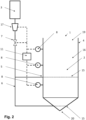
- Figure 1 shows a schematic representation of a first variant of a system 1 (for carrying out the method according to the invention) for processing concrete granulate 2.
- the system 1 comprises a storage tank 3 for storing a gas comprising CO2 and at least one container 4, 12 which is at least partially gas-tight.
- a first container 4 and a second (collection) container 12 are present. Both containers 4, 12 can be closed gas-tight and (in an open state) each have at least one opening (not shown) for receiving and/or removing the concrete granulate 2.
- the first container 4 comprises an inlet 5 for supplying the gas into the container 4, which can be fluidically connected to the storage tank 3 via a supply line 6.
- the second container 12 is operatively connected to the discharge line of the first container which is operatively connected to the outlet 13.
- An inlet valve 7 is arranged in the supply line 6 between the storage tank 3 and the first container 4, which serves to control a volume flow of gas supplied into the container 4.
- the inlet valve 7 can be a proportional valve.
- the inlet 5 can comprise several gas inlet nozzles. For rapid filling, gas inlet nozzles can be arranged in the receiving space and/or in the base and/or in the at least one side wall of the container 4 in a matrix-like manner (not shown).
- a pump 17 and an outlet valve 18 can be arranged in the line between the first and the second container 4, 12.
- the pump 17 can be designed to suck gas from the storage tank 3 into the first container 4 (with the inlet valve 7 and outlet valve 18 open).
- the pump 17 can have a Vacuum pump.
- a CO2 concentration sensor 8 can be arranged in the outlet of the first container 4 (or in the line between the two containers 4, 12). This serves to monitor how much CO2 is released from the container 4.
- Further sensors 8, 9, 10 are arranged in the first container 4. On the basis of the measured values of these sensors, a degree of CO2 absorption by the concrete granulate 2 can be determined, as described above.
- a control unit 11 serves to control the supply of gas depending on the degree of CO2 absorption.
- the sensors 8, 9, 10, the inlet valve 7, the outlet valve 18 and the pump 17 are operatively connected to the control unit 11 for this purpose.
- the inlet valve 7 and/or the outlet valve 18 can comprise a flow sensor.
- the control unit 11 can in particular be designed to automatically control the gas supply and/or the gas discharge until a predetermined CO2 saturation of the concrete granulate 2 is reached.
- the inlet valve 7 and the outlet valve 18 can first be opened.
- the pump 17 can then suck the gas from the storage tank 3 into the container 4.
- the concentration sensor 8 in the discharge line 14 of the container 4 can monitor the CO2 concentration.
- the outlet valve 18 can be closed.
- the inlet valve 7 can also be closed at least temporarily.
- the sensors 8, 9, 10 in the container 4 can monitor the pressure, the CO2 concentration and measure the temperature in the container. The measured values are used by the control unit to determine a measure of the absorption of CO2.
- gas comprising CO2 is fed into the container so that an optimal and as even as possible CO2 saturation, or enrichment, of the concrete granulate 2 with CO2 occurs.
- the excess gas can be released from the first container 4.
- this is advantageously fed into the collecting container 12, which is also filled with concrete granulate 2.
- the excess gas can advantageously be completely absorbed by the concrete granulate 2 in the collecting container 12.
- This can be checked in particular by a further CO2 concentration sensor 8, which is arranged in a discharge line of the collecting container 12.
- the weight difference of the concrete granulate 2 before gassing and the concrete granulate 2 enriched with CO2 after gassing can also be determined.
- a scale 22 can be arranged on the container 4.
- FIG. 2 shows a schematic representation of a second variant of a system 1 for processing concrete granulate 2.
- the system 1 also comprises a storage tank 3 for storing a gas comprising CO2 and a container 4 which is at least partially gas-tight.
- the container 4 is designed to be open at the top and comprises an upper opening 19 for filling in concrete granulate 2.
- a lower opening 20 is arranged for discharging the concrete granulate.
- the lower opening 20 is shown as being gas-tight.
- An annular side wall of the container is arranged between the upper and lower openings 19, 20. This is advantageously also gas-tight.
- the annular side wall can be round or square in cross section.
- the inlet valve 7 is opened and the container 4 is filled from bottom to top with gas comprising CO2.
- a pump 17 is arranged in the supply line 6 for this purpose.
- the container 4 advantageously comprises gas inlet nozzles 15 arranged in a ring. These can be arranged in the receiving space for the concrete granulate 2 of the container 4 and connected to one another by lines or surround the receiving space of the container. In the case shown, two ring-shaped groups of gas inlet nozzles 15 are arranged one above the other in the first direction. At least one CO2 concentration sensor 8 can be arranged in the container 4.
- CO2 concentration sensors 8 distributed in the first direction, each of which is operatively connected to a control unit 11.
- sensors such as sensors for measuring temperature, pressure or relative humidity, are also possible.
- the CO2 concentration sensors 8 advantageously continuously measure the CO2 concentration in the container 4.
- the control unit 11 controls the gas supply depending on a certain degree of CO2 absorption by the concrete granulate 2.
- the degree of CO2 absorption CO2 absorption is determined by the control unit 11 via the measurements of the sensor(s) 8, as described in connection with the method above.
- the extent of the CO2 absorption that has taken place can be the difference between the CO2 fed into the container 4 and the CO2 measured to be present in the container 4.
- gas comprising CO2 can be added to the container 4. This ensures efficient and uniform saturation of the concrete granulate 2 in the container 4.
- the CO2 concentration sensor 8 which is at the top in the direction of gravity, can be used to ensure that a predetermined fill level 16 of the gas in the container 4 is not exceeded. This can prevent gas from escaping from the upper opening 19.
- the process can be controlled in such a way that there is always a sufficiently thick layer of uncarbonated or only partially carbonated concrete granulate 2 on the surface (facing the first opening 19) in the container 4. This layer can serve as a filter layer to absorb any CO2 that may rise up unintentionally.
- this layer sinks downwards and can be provided with a predetermined CO2 saturation when the process is repeated, e.g. when further concrete granulate 2 is added from above.
Landscapes
- Chemical & Material Sciences (AREA)
- Engineering & Computer Science (AREA)
- Ceramic Engineering (AREA)
- Chemical Kinetics & Catalysis (AREA)
- Environmental & Geological Engineering (AREA)
- Health & Medical Sciences (AREA)
- Structural Engineering (AREA)
- General Chemical & Material Sciences (AREA)
- Organic Chemistry (AREA)
- Materials Engineering (AREA)
- Analytical Chemistry (AREA)
- Biomedical Technology (AREA)
- Oil, Petroleum & Natural Gas (AREA)
- Civil Engineering (AREA)
- Toxicology (AREA)
- Dispersion Chemistry (AREA)
- Mechanical Engineering (AREA)
- Gas Separation By Absorption (AREA)
- Treating Waste Gases (AREA)
- On-Site Construction Work That Accompanies The Preparation And Application Of Concrete (AREA)
- Processing Of Solid Wastes (AREA)
- Solid-Sorbent Or Filter-Aiding Compositions (AREA)
- Fertilizers (AREA)
Description
- Die vorliegende Erfindung betrifft ein Verfahren zum Aufbereiten von Betongranulatfür das anschliessende Recyceln des Betongranulats. Die vorliegende Erfindung betrifft insbesondere ein Verfahren zum Anreichern von Betongranulat mit CO2.
- Für die Betonherstellung ist neben Kies und Sand vor allem Zement von zentraler Bedeutung. Die Herstellung von Zement setzt jedoch nicht nur erhebliche Treibhausgasemissionen frei, sie ist auch ein wesentlicher Kostenfaktor in der Betonerzeugung. Heute schon nimmt das Recyceln von Beton einen wichtigen Stellenwert ein, wenn es darum geht, die Ressourcen Kies und Sand zu schonen. Allerdings kann durch herkömmliche Recyclingverfahren weder Zement wiedergewonnen noch Treibhausgasemissionen rückgängig gemacht oder vermieden werden. Das herkömmliche Recyceln erfolgt in der Regel durch den Rückbau abrissbereiter Häuser oder anderer Betonkörper. Der Abrissbeton wird anschliessend zu Betongranulat zerkleinert, das z.B. als Kiesersatz bei der Herstellung von neuen Beton dienen kann. Unter der Zugabe von neuem Zement entsteht Recyclingbeton. Dieser herkömmliche Recyclingbeton weist jedoch in der Regel verminderte mechanische Eigenschaften im Vergleich zu dem primären Beton auf. Unter primärem Beton wird nicht-recycelter Beton verstanden. Daher wird in der Regel in dem herkömmlich recycelten Beton wiederum der Zementgehalt um 10 % erhöht, um recycelten Beton in einer ähnlichen Qualität, wie die des primären Betons zu erhalten. Weiterhin kann das aus dem Abrissbeton gewonnene Betongranulat lose in einem ungebundenen Zustand, z.B. als Strassenbaumaterial, verwendet werden. Die Anwendung ist jedoch stark begrenzt, da herstellungsbedingt im Beton toxische Metalle enthalten sind, welche insbesondere im losen (ungebundenen) Zustand des aus dem Stand der Technik bekannten Betongranulats durch Regenwasser gelöst werden können und so das Grundwasser verunreinigen können. Aus den genannten Gründen gewinnt man durch heutiges Betonrecycling allenfalls minderwertigen Kiesersatz; allerdings lassen sich durch diese Rückgewinnung weder die Treibhausgasemissionen des Betons senken noch lässt sich das Betongranulat bedenkenlos lose verwenden.
- Aus dem Stand der Technik sind Verfahren zum Aufbereiten von Betongranulat bekannt. Beispiele hiervon finden sich in den Veröffentlichungen von Zhan et al. "Materials characteristics affecting CO2curing of concrete blocks containing recycled aggregates",CEMENT AND CONCRETE COMPOSITES, ELSEVIER APPLIED SCIENCE, BARKING, GB, Bd. 67, 2. Januar 2016, S. 50-59, (XP029409404), Englsen et AI. "Carbon dioxide uptake in demolished and crushed concrete",, 1. Dezember 2005, S. 1-40, OSLO, ISBN: 978-82-536-0900-3, (XP055520419), Sereng et al. "EFFECT OF CARBONATION ON RECYCLED CONCRETE AGGREGATES AND WATER ABSORPTION", International Workshop. CO2 Storage in Concrete - CO2STO2019, 24. Juni 2019), S. 1-11, (XP093134291), Dos Reis at al. "ACCELERATED CARBONATION OF COARSE AGGREGATES BY USING A ROTATING SYSTEM IN ORDER TO IMPROVE ITS PROPERTIES", Proceedings of the International Workshop CO2 Storage in Concrete - CO2STO2019, 1. Januar 2019, S. 99-108, (XP093134294).
- Die Aufgabe der Erfindung besteht darin, ein verbessertes Verfahren zum Aufbereiten von Betongranulat für das anschliessende Recyceln des Betongranulats bereitzustellen. Vorzugsweise werden dabei insbesondere die zuvor genannten Probleme bekannter Recyclingverfahren zumindest teilweise behoben.
- Zum Aufbereiten von Betongranulat für das anschliessende Recyceln des Betongranulats kann dieses mit Kohlenstoffdioxid (folgend als CO2 abgekürzt) behandeltwerden. Im Vergleich zu einem recycelten Referenzbeton (umfassend Zement, Kies, Sand und nicht angereichertes Betongranulat) mit einem angereicherten Beton mit im Wesentlichen gleicher Zusammensetzung kann der angereicherte Beton (umfassend Zement, Kies, Sand und mit CO2 angereichertes Betongranulat) eine höhere Druckfestigkeit bei im Wesentlichen gleichbleibendem Ausbreitmass aufweisen. Letzteres ist eine Kenngrösse für die Konsistenz von Frischbeton. Ebenfalls kann bei einer entsprechenden Reduzierung des Zementanteils des angereicherten Betons im Vergleich zu dem Referenzbeton mit unveränderter Zusammensetzung eine gleiche Druckfestigkeit erzielt werden.
- Diese Zusammenhänge können in den folgenden Tabellen nachvollzogen werden. Diese stellen Zusammensetzungen (Tabelle 1) und Messergebnisse (Tabelle 2) von einem Referenzbeton und verschiedenen Versuchsbetonen dar. Der Referenzbeton umfasst hierbei herkömmliches Betongranulat, welches nicht mit CO2 angereichert ist. Das Betongranulat der Versuchsbetone ist hingegen mit CO2 angereichert. Die Druckfestigkeit wurde gemäss der Norm SN EN 206: 2013 +A1:2016 und gemäss dem SIA Merkblatt '2030 Recyclingbeton' bestimmt. Das Ausbreitmass wurde gemäss der Norm SN EN 12350-5: 2019 bestimmt.
Tabelle 1 Bezeichnung Zement CEM II/B-LL (kg/m3) Wasser (kg/m3) Sand und Kies (kg/m3) Betongranulat (kg/m3) CO2 (kg/m3) Referenzbeton 315 191 1134 756 0 Versuchsbeton 1 315 186 1117 746 5.1 Versuchsbeton 2 315 183 755 1133 7.6 Versuchsbeton 3 290 167 1080 719 4.9 Tabelle 2 Bezeichnung Druckfestigkeit (N/mm2) Ausbreitmass (cm) Referenzbeton 43.8 48 Versuchsbeton 1 46.9 48 Versuchsbeton 2 47.7 47 Versuchsbeton 3 45.3 47 - Der angereicherte Beton mit entsprechend reduziertem Zementanteil (z.B. Versuchsbeton 3) weist somit deutlich reduzierte Treibhausgasemissionen auf. Beispielsweise können bei einer Zementreduktion von 10% die Emissionen der Betonherstellung um ca. 8.5% gesenkt werden. Andererseits können bereits vorhandene CO2 Emissionen während des Verfahrens an das Betongranulat gebunden und somit reduziert werden. Beispielsweise können durchschnittlich bei 10 kg CO2 pro 1 000kg Betongranulat die Emissionen im Schnitt um weitere 4 % gesenkt werden. Unter idealen Voraussetzungen kann die Technologie die CO2 Emissionen der Herstellung von Recyclingbeton somit um ca. 12,5 % senken.
- Des Weiteren hat sich gezeigt, dass der angereicherte Beton einen höheren Karbonatisierungswiderstand aufweist. Der Karbonatisierungswiderstand ist hierbei ein entscheidender Faktor für die Korrosion einer im Beton vergossenen Bewehrung und auftretenden Schäden im Betonbau. Ebenso kann die Anreicherung des Betongranulats mit CO2 dazu führen, dass die oben erwähnten toxischen Metalle besser gebunden werden und dessen ungewolltes Entweichen in die Umwelt deutlich reduziert werden kann. Dies erweitert die Anwendungsmöglichkeiten des losen Betongranulats.
- Ein anspruchsgemässes Verfahren zum Aufbereiten, insbesondere zum Anreichern mit CO2, von Betongranulat für das anschliessende Recyceln umfasst die folgenden Verfahrensschritte: Befüllen eines zumindest bereichsweise gasdichten Behälters mit Betongranulat. Zufuhr eines Volumenstroms an Gas umfassend CO2 in Abhängigkeit eines über mindestens einen Sensor bestimmten Masses einer erfolgten CO2-Absorption durch das Betongranulat im Behälter. Die Zufuhr des Gases kann hierbei kontinuierlich oder nicht kontinuierlich erfolgen. Feststellen, ob eine vorgegebene CO2-Sättigung des Betongranulats zwischen 5kg CO2 pro 1000 kg und 15kg CO2 pro 1000 kg erreicht ist, und anderenfalls Fortführung des vorherigen Verfahrensschritts betreffend die Zufuhr des Gases. Sollte noch keine vorgegebene CO2-Sättigung des Betongranulats vorliegen, kann das Gas je nach Anwendung kontinuierlich oder nicht-kontinuierlich zugeführt werden bis diese erreicht wird. Ferner umfasst das Verfahren die Entnahme des mit CO2 angereicherten Betongranulats aus dem Behälter. Nach der Entnahme des Betongranulats kann dieses in einem weiteren Verfahrensschritt zur Herstellung von recycelten (angereicherten) Beton umfassend das mit CO2 angereicherte Betongranulat verwendet werden. Hierzu kann das mit CO2 angereicherte Betongranulat mit Zement, Wasser, Sand und Kies zu Beton verarbeitet werden.
- Unter einer CO2-Absorption des Betongranulats wird verstanden, dass das CO2 in das Betongranulat diffundiert und eine chemische Reaktion eingeht. Für diesen Absorptionsprozess muss kein zusätzliches Wasser, insbesondere in flüssiger Form, in den Behälter dazugegeben werden. Das Betongranulat umfasst Poren, in welche das CO2 diffundieren kann. In den Poren kann Wasser vorhanden sein, auch Porenwasser genannt, mit welchem das CO2 eine chemische Reaktion eingeht. Das Porenwasser steht mit den Zementphasen des Betongranulats in einem Phasengleichgewicht und umfasst Kalziumionen. Wenn CO2 (chemisch) absorbiert wird entstehen Karbonat- und Bikarbonationen. Die entstehende Porenlösung wird so in Bezug auf Kalziumkarbonat (CaCO3), respektive deren polymorphe Minerale Kalzit, Argonot und Veterit, übersättigt und die Poren ausgefüllt.
- Das Betongranulat kann je nach Zusammensetzung jedoch nur eine bestimmte Menge an CO2 aufnehmen. Diese maximale CO2-Sättigung kann je nach Zusammensetzung zwischen 30 - 45 kg CO2 pro 1000 kg Betongranulat liegen. Wenn beispielsweise pro Ausgangsvolumen an Gas keine Änderung der CO2-Konzentration und/oder Änderung des Druckes mehr festgestellt werden kann, ist die maximale CO2-Sättigung des Betongranulats erreicht. Jedoch wird das erfindungsgemässe Verfahren vorher beim Erreichen einer vorgegebenen CO2-Sättigung unterhalb der maximalen CO2-Sättigung abgebrochen. Hohe Sättigungswerte können nur bei ausreichend langer Begasung mit CO2 erreicht werden und benötigen entsprechend grössere Mengen an CO2. Gute Materialeigenschaften werden jedoch bereits bei einer vorgegebenen CO2-Sättigung zwischen 5kg CO2 pro 1000kg bis 15kg CO2 pro 1000kg erreicht. Dies entspricht einer vorgegebenen CO2-Sättigung von etwa 10% bis 50% der maximalen CO2-Sättigung.
- Die Menge des absorbierten CO2 im Betongranulat nimmt in der Regel exponentiell über die Zeit ab bis die maximale CO2-Sättigung erreicht ist. In einer nicht unter den Wortlaut des Anspruchs fallenden Variante kann die vorgegebene CO2-Sättigung beispielsweise als erreicht betrachtet werden, wenn über ein bestimmtes Zeitintervall die Änderung des Masses der CO2-Absorption kleiner ist als ein vorgegebener Grenzwert. In einer alternativen oder zusätzlichen nicht unter den Wortlaut des Anspruchs fallenden Variante kann zur Feststellung der vorgegebenen CO2-Sättigung beispielsweise das über den mindestens einen Sensor bestimmte Mass der erfolgten CO2-Absorption über die Zeit aufgetragen und extrapoliert werden. Über die Extrapolation kann ein (theoretischer) Grenzwert des Masses der erfolgten CO2-Absorption bestimmt werden, welcher der maximalen CO2-Sättigung des Betongranulats im Behälter entspricht. Bei Erreichen eines vorgegebenen Prozentsatzes dieses Grenzwertes (respektive der vorgegebenen CO2-Sättigung) kann die Gaszufuhr beendet werden.
- Die Zufuhr des Gases in den Behälter, respektive eine Einstellung des zugeführten Volumenstroms in den Behälter, kann über eine Verstellung eines Einlassventils vorgenommen werden. Das Einlassventil kann in der Zuleitung des Behälters angeordnet sein. Die Einstellung des Einlassventils, respektive des Volumenstroms, in Abhängigkeit des Masses der erfolgten CO2-Absorption erfolgt durch eine Kontrolleinheit, welche mit dem mindestens einen Sensor, sowie dem Einlassventil wirkverbunden ist. Mit Vorteil gleicht der zugeführte Volumenstrom an Gas (nach einer initialen Befüllung des Behälters) hierbei das bereits absorbierte CO2 aus. Auf diese Weise liegt im Behälter eine möglichst gleichbleibende CO2-Konzentration vor. Dies hat den Vorteil, dass bei höherer CO2-Konzentration und gleichmässiger Verteilung von CO2 im Behälter das Verfahren einerseits schneller verläuft und andererseits eine gleichmässige Anreicherung von CO2 in dem Betongranulat erzielt werden kann. Die Kontrolleinheit kann hierbei aus der bekannten Zusammensetzung des Gases, respektive dem CO2 Gehalt des Gases, sowie aus dem bekannten zugeführten Volumenstrom durch das Einlassventil eine theoretisch im Behälter vorhandene Menge an CO2 bestimmen, welche ohne Absorption von CO2 vorläge. Ebenso kann ein theoretischer Druck im Behälter bestimmt werden. Das Einlassventil kann hierzu einen Durchflusssensor zur Bestimmung des durch das Einlassventil durchgeführten Volumenstroms umfassen, oder ein Durchflusssensor kann dem Einlassventil vor-oder nachgeschaltet sein. Alternativ oder ergänzend kann zur Verwendung des Durchflusssensors der durchgeführte Volumenstrom in Abhängigkeit der Einstellung des Einlassventils als Datensatz in einer Kontrolleinheit hinterlegt sein.
- Die Zufuhr des Gases kann zumindest vorübergehend unterbrochen werden (nicht-kontinuierliche Zufuhr des Gases). Dies kann durch wiederholtes Durchführen der folgenden Schrittfolge geschehen: Öffnen des mit dem Behälter fluidisch wirkverbundenen Einlassventils, Zufuhr des Gases umfassend CO2 in den Behälter und Schliessen des Einlassventils. Bei geschlossenem Einlassventil kann das Mass der erfolgten CO2-Absorption besonders einfach bestimmt werden. Der bei geöffneten Einlassventil zugeführte Volumenstrom an Gas gleicht mit Vorteil das zwischenzeitlich (während des geschlossenen Einlassventils) absorbierte CO2 aus. Diese nicht-kontinuierliche Begasung kann so lange fortgeführt werden, bis die vorgegebene CO2-Sättigung des Betongranulats erreicht ist. Eine nicht-kontinuierliche Zufuhr des Gases eignet sich besonders bei Behältern, welche (während der Begasung) bereichsweise offen zur Umwelt beziehungsweise Umgebungsluft sind. Ein solcher Behälter kann insbesondere nach oben offen sein.
- Alternativ zu der nicht-kontinuierlichen Begasung kann der Volumenstrom in Abhängigkeit des Masses der erfolgten CO2-Absorption über die Dauer der Begasung kontinuierlich angepasst werden (kontinuierliche Zufuhr des Gases). Mit Vorteil gleicht der zugeführte Volumenstrom an Gas hierbei das bereits absorbierte CO2 aus. Bei einer exponentiell über die Zeit abnehmenden Absorption von CO2 kann der zugeführte Volumenstrom so eingestellt werden, dass dieser entsprechend exponentiell abnimmt.
- Eine (initiale) Befüllung des Behälters mit dem Gas kann durchgeführt werden, bis ein gewünschter Füllstand des Behälters mit dem Gas erreicht ist. Alternativ oder in Ergänzung kann die (initiale) Befüllung des Behälters durchgeführt werden, bis im Behälter eine vorgegebene CO2-Konzentration, insbesondere eine Konzentration von über 95% CO2, vorliegt. Nach der initialen Befüllung kann der Volumenstrom reduziert werden (weitere kontinuierliche Zufuhr) oder zwischenzeitlich unterbrochen werden (nicht-kontinuierliche Zufuhr). Hierbei kann der weiter zugeführte Volumenstrom, wie bereits beschrieben, derart kontrolliert werden, dass das im Behälter absorbierte CO2 ausgeglichen wird.
- Zur Bestimmung des Masses der erfolgten CO2-Absorption durch das Betongranulat kann mindestens ein Sensor im Behälter angeordnet sein, respektive mit diesem fluidisch wirkverbunden sein. Der mindestens eine Sensor kann beispielsweise ein CO2-Konzentrationssensor zur Messung der CO2-Konzentration im Behälter sein. Aus der zugeführten Menge an CO2 (und ggf. einer gemessenen Menge an abgeführten CO2) kann eine theoretische Menge an CO2 im Behälter (ohne Absorption) bestimmt werden. Das Mass für die Absorption kann somit aus der Differenz der theoretischen Menge an CO2 und der tatsächlichen (gemessenen) Menge an CO2 über den Konzentrationssensor im Behälter bestimmt werden. Die vorgegebene CO2-Sättigung wird als erreicht erachtet, bzw. die Begasung abgebrochen, wenn ein Grenzwert für die oben beschriebene Differenz über die gesamte bisherige Verfahrensdauer erreicht wurde. Wie oben beschrieben kann die vorgegebene CO2-Sättigung in einer nicht unter den Wortlaut des Anspruchs fallenden Variante kann beispielsweise erreicht sein, wenn über ein bestimmtes Zeitintervall die Differenz der theoretischen Menge an CO2 und der tatsächlichen Menge an CO2 im Behälter kleiner ist als ein vorgegebener Grenzwert. Wiederum alternativ und nicht unter den Wortlaut des Anspruchs fallend, kann die vorgegebene CO2-Sättigung erreicht sein, wenn ein durch Extrapolation bestimmter theoretischer Grenzwert des Masses der CO2-Absorption erreicht ist. Die Bestimmung des Masses der erfolgten CO2-Absorption über die Messung der CO2-Konzentration ist besonders geeignet bei nicht gasdicht verschliessbaren Behältern. Alternativ oder ergänzend zu einem CO2-Konzentrationssensor kann ein Mass der erfolgten CO2-Absorption durch das Betongranulat ebenfalls durch eine Messung des Druckes bestimmt werden. Der Druck eines vorgegebenen Volumens an Gas umfassend CO2 sinkt, wenn das CO2 mit dem Betongranulat in Kontakt tritt und CO2 absorbiert wird. D.h. die Differenz eines theoretischen Druckes, welcher im Behälter ohne Absorption vorliegen müsste, und dem tatsächlich im Behälter gemessenen Druckes kann als Mass der erfolgten CO2-Absorption herangezogen werden. Der theoretische Druck kann über das bekannte Behältervolumen, sowie dem zugeführten (und optional einem abgeführten) Volumenstrom zumindest annähernd bestimmt werden. Die Bestimmung des Masses der erfolgten CO2-Absorption über die Messung des Druckes eignet sich besonders für einen gasdicht verschliessbaren Behälter, insbesondere bei einer nicht-kontinuierlichen Zufuhr an Gas in den Behälter.
- Ergänzend kann die Bestimmung des Masses der erfolgten CO2-Absorption zusätzlich eine gemessene Temperatur berücksichtigen. Da bei der chemischen Reaktion Hitze freigesetzt wird, kann diese Temperaturänderung ebenfalls auf den Druck Einfluss nehmen. Durch eine ergänzende Temperaturmessung kann der Einfluss der Temperaturänderung auf den theoretischen Druck berücksichtig werden. Eine ergänzende Temperaturmessung kann ebenfalls bei der Bestimmung des Masses der erfolgten CO2-Absorption über die Messung der CO2-Konzentration berücksichtigt werden.
- Alternativ oder ergänzend kann die Bestimmung des Masses der erfolgten CO2-Absorption zusätzlich ein gemessenes Gewicht berücksichtigen. Hierzu kann mindestens ein Sensor eine mit dem Behälter und der Kontrolleinheit wirkverbundene Waage beziehungsweise Wägezelle sein. Beispielsweise kann über das vor der Begasung gemessene Gewicht des Betongranulats das zur Verfügung stehende Volumen im Behälter für die Begasung zumindest annähernd bestimmt werden. Dieses kann z.B. in die Bestimmung des theoretischen Druckes einfliessen. Weiterhin kann die Gewichtsdifferenz des Betongranulats vor der Begasung und des mit CO2 angereicherten Betongranulats nach der Begasung bestimmt werden. Diese gibt Rückschluss über die konkret absorbierte Menge an CO2. Diese Informationen können beispielsweise von Unternehmen für CO2 Zertifikate, auch Emissionszertifikate genannt, genutzt werden, um mit diesen zu handeln.
- Je nach Ausführung kann ergänzend die relative Feuchte im Behälter gemessen werden, da bei der Absorption von CO2 gasförmiges Wasser freigesetzt wird. Während das zugeführte Gas eine relative Feuchte von weniger als 1 % aufweisen kann, kann im Behälter bei Erreichen der maximalen CO2-Sättigung eine relative Feuchte von 50 % - 95 % vorliegen. Die Bestimmung des Masses der erfolgten CO2-Absorption kann somit zusätzlich die gemessene relative Feuchte berücksichtigen.
- Wie bereits beschrieben, kann die Bestimmung des Masses der erfolgten CO2-Absorption durch die Messungen des Druckes und/oder der CO2-Konzentration durch eine Messung des Gewichtes und/oder der Temperatur und/oder der relativen Feuchte genauer bestimmt werden. Beispielsweise können die gemessenen und/oder bekannten Werte über physikalische Zusammenhänge, wie z.B. die ideale Gasgleichung und Massenerhaltungssätze, miteinander in Relation gebracht werden. Dies ermöglicht eine genauere und umfänglichere Überwachung der erfolgten CO2-Absorption.
- Je nach Zusammensetzung kann das in den Behälter zugeführte Gas neben CO2 ebenfalls gasförmiges Wasser und/oder Stickstoff und/oder Sauerstoff umfassen. Das in den Behälter zuzuführende Gas kann vor seiner Zuführung in den Behälter in einem Speichertank als Flüssigkeit und/oder als Gas gespeichert sein. Mit Vorteil umfasst das Gas 95 % bis 100 % CO2. Je nach Anwendung kann das Gas erneuerbares CO2 umfassen. Unter erneuerbarem CO2 wird biogenes CO2 oder aus der Atmosphäre gewonnenes CO2 verstanden. Biogenes CO2 hat den Vorteil, dass es in der Regel bereits in reiner Form gewonnen werden kann und nicht mehr aufbereitet werden muss. Biogenes CO2 kann z.B. als Nebenprodukt der Biomethanproduktion oder aus der Verbrennung von Biomasse (biologisches Material, welches Kohlenstoff, Wasserstoff und Sauerstoff umfasst) gewonnen werden. Alternativ kann das Gas ebenfalls ein Abgas umfassend 10 - 25 % CO2 sein. Beispielsweise kann ein Abgas aus einem Zementwerk zur Herstellung von Zement verwendet werden.
- Primärer Beton umfasst in der Regel Sand, Kies und Zement. Das Betongranulat, welches z.B. als Abrissbeton gewonnen wird, kann je nach Art der vorherigen Verwendung, zudem Mörtel umfassen. Das Betongranulat umfasst in der Regel 4 - 10 Gewichtsprozent Calciumoxid. Das Betongranulat umfasst insbesondere hydrierten Zement. Hydrierter Zement ist hierbei derart zu verstehen, dass der Zement eine Reaktion mit Wasser durchgeführt hat und dieses an den Zement angelagert ist. Diese Reaktion wird als Hydratation und das Reaktionsprodukt als hydrierter Zement bezeichnet. Bei einer Hydratation kann der Zement bis zu 25 % seiner Masse an Wasser chemisch und bis zu 15 % seiner Masse physikalisch binden. Zum Aufbereiten kann der Abbruchbeton zerkleinert werden. Gute Resultate beim Aufbereiten werden erzeugt, wenn die Partikel einen Durchmesser von 0.05 mm bis 50 mm aufweisen. Zum Aufbereiten können die Bestandteile des Betongranulats in der Regel nicht voneinander getrennt werden.
- Nach Erreichen der vorgegebenen CO2-Sättigung kann das im Behälter vorhandene überschüssige Gas abgelassen werden. Dieses kann zur Wiederverwendung aufbereitet werden und in den Speichertank der Anlage zurückgeführt werden. Alternativ kann das überschüssige Gas ebenfalls in einen mit Betongranulat befüllbaren Auffangbehälter eingebracht werden, in welchem das Verfahren von neuem durchgeführt wird. Das Verfahren kann beispielsweise alternierend in dem Behälter und dem Auffangbehälter durchgeführt werden. Alternativ kann der mit weiterem Betongranulat befüllte Auffangbehälter als ein passiver Filter, d.h. ohne aktive Kontrolle der CO2-Sättigung, dienen. Das in diesem angeordnete Betongranulat kann das überschüssige Gas zumindest teilweise, insbesondere aber auch vollständig, absorbieren.
- Vor der Zufuhr des Gases umfassend CO2 kann neben dem Betongranulat Luft im Behälter vorhanden sein. Wenn das Einlassventil für die Begasung geöffnet wird, entsteht somit ein Gasgemisch im Behälter, welches CO2 und Luft umfasst. Um die CO2-Konzentrationim Behälter zu erhöhen kann, insbesondere bei der initialen Befüllung des Behälters, neben der Zufuhr von Gas umfassend CO2 kontinuierlich oder nicht kontinuierlich das Gasgemisch aus dem Behälter abgelassen werden Bei diesem Vorgang erhöht sich mit Vorteil der Anteil an CO2 im Behälter. Das aus dem Behälter abgelassene Gasgemisch kann, wie für das überschüssige Gas beschrieben, aufbereitet werden oder in einen Auffangbehälter geführt werden. Nach Erreichen einer vorgegebenen CO2-Konzentration im Behälter kann die Abfuhr des Gasgemisches und optional zumindest vorrübergehend ebenfalls die Zufuhr des Gases gestoppt werden.
- Die Abfuhr des Gases aus dem Behälter kann über ein Auslassventil kontrolliert werden. Das Auslassventil kann, wie das Einlassventil, einen Durchflusssensor zur Bestimmung des durch das Auslassventil durchgeführten Volumenstroms umfassen, oder ein Durchflusssensor kann dem Auslassventil vor- oder nachgeschaltet sein. Der vor- oder nachgeschaltete Durchflusssensor ist ebenfalls mit der Kontrolleinheit wirkverbunden. Alternativ oder ergänzend kann zur Verwendung des Durchflusssensors der durchgeführte Volumenstrom in Abhängigkeit der Einstellung des Auslassventils als Datensatz in einer Kontrolleinheit hinterlegt sein. Ergänzend kann dem Auslassventil ebenfalls ein CO2- Konzentrationssensor vor- oder nachgeschaltet sein.
- Die Zufuhr und/oder die Abfuhr des Gases kann durch mindestens eine Pumpe kontrolliert werden, welche mit der Kontrolleinheit wirkverbunden ist. Die Zufuhr des Gases in den Behälter und/oder die Abfuhr des Gasgemisches aus dem Behälter und/oder die Abfuhr des überschüssigen Gases aus dem Behälter kann z.B. durch einen Unterdruck (in Relation zu einem Umgebungsdruck) erzeugt werden. Der Unterdruck kann zwischen 80000 und 96000 Pascal liegen. Jedoch kann das Verfahren ebenfalls bei Umgebungsdruck oder grösseren Drücken durchgeführt werden.
- Nachstehend wird eine Anlage (zum Durchführen des erfindungsgemässen Verfahrens) zum Aufbereiten von Betongranulat, insbesondere zum Anreichern mit CO2, für das anschliessende Recyceln des Betongranulats erläutert. Die Anlage umfasst einen Speichertank sowie einen zumindest bereichsweise gasdichten Behälter. Das in den Behälter zuzuführende Gas kann zuvor in flüssiger Form und/oder in gasförmiger Form in dem Speichertank gespeichert oder zwischengelagert werden. Der Behälter kann hierbei mindestens eine Öffnung zur Aufnahme und/oder Entnahme des Betongranulats aufweisen. Der Behälter umfasst weiter einen Einlass zur Zuführung des Gases in den Behälter, welcher über eine Zuleitung mit dem Speichertank fluidisch wirkverbindbar ist. Ein Einlassventil dient hierbei zur Kontrolle des zuzuführenden Volumenstroms an Gas in den Behälter. Das Einlassventil kann ein Proportionalventil sein. Die Anlage umfasst ebenfalls mindestens einen Sensor (wie oben beschrieben) und eine Kontrolleinheit, welche mit dem mindestens einen Sensor und dem Einlassventil wirkverbunden ist. Der Sensor dient zur Bestimmung eines Masses der erfolgten CO2-Absorption durch das Betongranulat im Behälter durch die Kontrolleinheit. Die Kontrolleinheit ist dazu ausgelegt den Volumenstrom an Gas durch das Einlassventil zu kontrollieren. Des Weiteren kann die Kontrolleinheit ebenfalls mit einer Pumpe wirkverbunden sein. Die Pumpe kann in einer Zuleitung oder einer Ableitung des Behälters angeordnet sein. Die Pumpe kann eine Vakuumpumpe sein. Diese kann zur Erzeugung eines Unterdruckes, wie oben beschrieben, dienen.
- Die Kontrolle des Volumenstroms erfolgt mit Vorteil automatisch. Entsprechend dem oben beschriebenen Verfahren ist die Kontrolleinheit dazu ausgelegt, die folgenden Schritte wiederholt durchzuführen: Zufuhr von einem Volumenstrom an Gas umfassend CO2 in Abhängigkeit des über den mindestens einen Sensor bestimmten Masses der erfolgten CO2-Absorption durch das Betongranulat im Behälter und feststellen, ob eine vorgegebene CO2-Sättigung des Betongranulats erreicht ist. Falls die vorgegebene CO2-Sättigung des Betongranulats noch nicht erreicht ist, kann der vorherige Schritt der Gaszufuhr fortgeführt werden, bis die vorgegebene CO2-Sättigung vorliegt.
- Für eine effiziente Begasung ist der Behälter mit Vorteil zumindest bereichsweise gasdicht. Je nach Ausgestaltung des Behälters kann dieser einen Behälterboden und mindestens eine umlaufende Seitenwand umfassen. Diese umgeben einen Aufnahmeraum des Behälters zur Aufnahme des Betongranulats. Die mindestens eine Seitenwand kann beispielsweise röhrenförmig sein. Die röhrenförmige Seitenwand kann einen runden oder einen eckigen Querschnitt aufweisen. Mit Vorteil sind der Boden und die mindestens eine Seitenwand gasdicht ausgestaltet. Je nach Anwendung kann das Betongranulat über eine einzige Öffnung eingefüllt und entnommen werden. Mit Vorteil umfasst die Anlage jedoch eine erste Öffnung zum Befüllen mit Betongranulat und eine zweite Öffnung zum Entnehmen des Betongranulats. Beispielsweise können eine erste (obere) Öffnung und eine dieser in Bezug auf die Gravitationsrichtung gegenüberliegende zweite (untere) Öffnung vorgesehen sein. In diesem Fall kann beim Öffnen der zweiten (unteren) Öffnung das Betongranulat automatisch aus den Behälter fallen. Bei dieser Ausführungsform kann insbesondere lediglich die zweite (untere) Öffnung gasdicht verschliessbar ausgestaltet sein, während die erste (obere) Öffnung offengelassen werden kann. Jedoch sind auch Ausgestaltungen möglich, bei denen beide Öffnungen gasdicht verschliessbar sind. Hierzu kann die Anlage mindestens einen Deckel umfassen.
- Der mindestens eine Sensor ist mit Vorteil im Behälter angeordnet. Dies umfasst Ausführungsformen, bei denen der Sensor in einer Ausbuchtung, einem Rohrstück, oder ähnlichem an einer Seitenwand angeordnet ist und mit dem Aufnahmeraum des Behälters fluidisch wirkverbunden ist. Um das Mass der erfolgten CO2-Absorption durch das Betongranulat bestimmen zu können, können verschiedene Sensortypen (wie oben beschrieben) verwendet werden. Ebenfalls ist eine beliebige Kombination einer oder mehrerer dieser Sensortypen denkbar. Da CO2 schwerer ist als Luft und sich daher grundsätzlich eher am Boden des Behälters ansammelt, können z.B. mehrere Konzentrationssensoren im Behälter in Richtung der Schwerkraft übereinander angeordnet sein.
- Für eine gleichmässige und schnelle Zufuhr an CO2 in den Behälter kann der Einlass mehrere Gaseinlassdüsen umfassen. Diese können in dem Behälterboden und/oder mindestens einer Seitenwand angeordnet sein, insbesondere matrizenartig angeordnet sein. Auch eine matrizenartige Verteilung mehrerer Einlassdüsen im Aufnahmeraum des Behälters ist denkbar. Diese können über Rohrleitungen miteinander verbunden sein. Je nach Ausgestaltung des Behälters können die Gaseinlassdüsen auch um den Aufnahmeraum des Behälters, z.B. ringförmig, verteilt angeordnet sein. Der Behälter kann weiterhin einen Auslass zum Auslassen des Gases aus dem Behälter umfassen. In einer mit einem Auslass wirkverbundenen Ableitung kann ergänzend ein Auslassventil und/oder ein Durchlasssensor und/oder ein weiterer CO2-Konzentrationssensor angeordnet sein.
- Je nach Ausgestaltung der Anlage kann diese ebenfalls mehrere Behälter umfassen. Beispielsweise kann die Begasung des Betongranulats in den mehreren Behältern parallel vorgenommen werden. Alternativ können die mehreren Behälter hintereinander in Reihe geschaltet werden. Überschüssiges Gas aus dem ersten Behälter kann z.B. in einen zweiten Behälter/ Auffangbehälter geleitet werden um in diesem das Verfahren, wie oben beschrieben, zu wiederholen. Alternativ denkbar ist jedoch auch, dass das überschüssige Gas aus dem ersten Behälter lediglich passiv von dem in dem Auffangbehälter angeordneten Betongranulat zumindest teilweise, insbesondere aber vollständig, absorbiert wird. Der zweite Behälter / Auffangbehälter kann somit mit der Ableitung des ersten Behälters fluidisch wirkverbindbar sein. Alternativ oder in Ergänzung kann der zweiten Behälter / Auffangbehälter ebenfalls mit dem Speichertank fluidisch über eine separate Zuleitung mit einem (zweiten) Einlassventil wirkverbindbar sein.
- Die beschriebenen Ausführungsformen der Anlage können zur Ausführung des erfindungsgemässen Verfahrens dienen. Die zuvor beschriebenen Ausführungsformen des Verfahrens offenbaren zugleich entsprechend ausgestaltete Ausführungen der Anlage zur Durchführung des Verfahrens und umgekehrt.
- Anhand der in den nachfolgenden Figuren gezeigten Ausführungsbeispiele und der dazugehörigen Beschreibung werden Aspekte der Erfindung näher erläutert. Es zeigen:
- Fig. 1
- Eine erste Variante einer Anlage zum Aufbereiten von Betongranulat;
- Fig. 2
- Eine zweite Variante einer Anlage zum Aufbereiten von Betongranulat.
-
Figur 1 zeigt eine schematische Darstellung einer ersten Variante einer Anlage 1 (zum Durchführen des erfindungsgemässen Verfahrens) zum Aufbereiten von Betongranulat 2. Die Anlage 1 umfasst einen Speichertank 3 zum Speichern von einem Gas umfassend CO2 und mindestens einen zumindest bereichsweise gasdichten Behälter 4, 12. Im gezeigten Ausführungsbeispiel ist ein erster Behälter 4 und ein zweiter (Auffang-) Behälter 12 vorhanden. Beide Behälter 4, 12 können gasdicht verschliessbar sein und weisen (in einem geöffneten Zustand) je mindestens eine Öffnung (nicht gezeigt) zur Aufnahme und/oder Entnahme des Betongranulats 2 auf. Der erste Behälter 4 umfasst einen Einlass 5 zur Zuführung des Gases in den Behälter 4, welcher über eine Zuleitung 6 mit dem Speichertank 3 fluidisch wirkverbindbar ist. Der zweite Behälter 12 ist mit der an den Auslass 13 wirkverbundenen Ableitung des ersten Behälters wirkverbunden. In der Zuleitung 6, zwischen Speichertank 3 und dem ersten Behälter 4 ist ein Einlassventil 7 angeordnet, welches zur Kontrolle eines zugeführten Volumenstroms an Gas in den Behälter 4 dient. Das Einlassventil 7 kann ein Proportionalventil sein. Der Einlass 5 kann mehrere Gaseinlassdüsen umfassen. Für eine schnelle Befüllung können in dem Aufnahmeraum und/oder in dem Boden und/oder in der mindestens einen Seitenwand des Behälters 4 matrizenartig Gaseinlassdüsen angeordnet sein (nicht gezeigt). In der Leitung zwischen dem ersten und dem zweiten Behälter 4, 12 können eine Pumpe 17 und ein Auslassventil 18 angeordnet sein. Die Pumpe 17 kann dazu ausgelegt sein (bei geöffneten Einlassventil 7 und geöffneten Auslassventil 18) Gas aus dem Speichertank 3 in den ersten Behälter 4 zu saugen. Hierfür kann die Pumpe 17 eine Vakuumpumpe sein. Ergänzend kann ein CO2-Konzentrationssensor 8 in der Ableitung des ersten Behälters 4 (respektive in der Leitung zwischen den beiden Behältern 4, 12) angeordnet sein. Dieser dient zur Überwachung, wieviel CO2 aus dem Behälter 4 ausgelassen wird. - In dem ersten Behälter 4 sind weitere Sensoren 8, 9, 10 angeordnet. Auf Basis der gemessenen Werte dieser Sensoren kann ein Mass einer erfolgten CO2-Absorption durch das Betongranulat 2 bestimmt werden, wie oben beschrieben. Eine Kontrolleinheit 11 dient dazu die Zufuhr an Gas in Abhängigkeit des Masses der erfolgten CO2-Absorption zu kontrollieren. Die Sensoren 8, 9, 10, das Einlassventil 7, das Auslassventil 18 und die Pumpe 17 sind hierzu mit der Kontrolleinheit 11 wirkverbunden. Das Einlassventil 7 und/oder das Auslassventil 18 können einen Durchflusssensor umfassen. Die Kontrolleinheit 11 kann insbesondere dazu ausgelegt sein, die Gaszufuhr und/oder die Gasabfuhr automatisch zu kontrollieren, bis eine vorgegebene CO2-Sättigung des Betongranulats 2 erreicht ist.
- Zur initialen Befüllung des Behälters 4 umfassend das Betongranulat 2 mit dem Gas kann zunächst das Einlassventil 7 und das Auslassventil 18 geöffnet werden. Die Pumpe 17 kann dann das Gas aus dem Speichertank 3 in den Behälter 4 saugen. Der Konzentrationssensor 8 in der Ableitung 14 des Behälters 4 kann die CO2-Konzentration überwachen. Wenn eine gewünschte maximale CO2-Konzentration im Behälter 4 erreicht ist kann das Auslassventil 18 geschlossen werden. Das Einlassventil 7 kann ebenfalls zumindest vorübergehend geschlossen werden. Die Sensoren 8, 9, 10 im Behälter 4 können den Druck, die CO2-Konzentration und die Temperatur im Behälter messen. Die gemessenen Werte dienen der Kontrolleinheit dazu, ein Mass für die Absorption von CO2 zu bestimmen. In Abhängigkeit des Masses für die Absorption wird Gas umfassend CO2 in den Behälter nachgeführt, so dass eine optimale und möglichst gleichmässige CO2-Sättigung, respektive Anreichung, des Betongranulats 2 mit CO2 erfolgt. Wenn die vorgegebene CO2-Sättigung erreicht ist, kann das überschüssige Gas aus dem ersten Behälter 4 ausgelassen werden. Im Vorteil wird dieses, wie im gezeigten Fall, in den ebenfalls mit Betongranulat 2 befüllten Auffangbehälter 12 geleitet. In diesem kann das überschüssige Gas mit Vorteil vollständig durch das Betongranulat 2 im Auffangbehälter 12 absorbiert werden. Dies kann insbesondere durch einen weiteren CO2-Konzentrationssensor 8, welcher in einer Ableitung des Auffangbehälters 12 angeordnet ist, überprüft werden. Alternativ oder ergänzend kann ebenfalls die Gewichtsdifferenz des Betongranulats 2 vor der Begasung und des mit CO2 angereicherte Betongranulat 2 nach der Begasung bestimmt werden. Für die Messung des Gewichts, respektive der Gewichtsdifferenz, kann eine Waage 22 am Behälter 4 angeordnet sein.
-
Figur 2 zeigt eine schematische Darstellung einer zweiten Variante einer Anlage 1 zum Aufbereiten von Betongranulat 2. Die Anlage 1 umfasst ebenfalls einen Speichertank 3 zum Speichern von einem Gas umfassend CO2 und einen zumindest bereichsweise gasdichten Behälter 4. Im gezeigten Beispiel ist der Behälter 4 nach oben hin offen ausgestaltet und umfasst eine obere Öffnung 19 zum Einfüllen von Betongranulat 2. In eine erste Richtung gegenüberliegend der oberen Öffnung 19 (Richtung der Schwerkraft) ist eine untere Öffnung 20 zum Auslassen des Betongranulats angeordnet. Die untere Öffnung 20 ist gasdicht verschlossen dargestellt. Eine ringförmige Seitenwand des Behälters ist zwischen der oberen und der unteren Öffnung 19, 20 angeordnet. Diese ist mit Vorteil ebenfalls gasdicht. Die ringförmige Seitenwand kann im Querschnitt rund oder eckig ausgestaltet sein. Nach dem Befüllen mit Betongranulat 2 wird das Einlassventil 7 geöffnet und der Behälter 4 von unten nach oben mit Gas umfassend CO2 befüllt. Hierzu ist im gezeigten Fall eine Pumpe 17 in der Zuleitung 6 angeordnet. Andere Anordnungen sind jedoch ebenfalls denkbar. Für eine schnelle Zufuhr von Gas umfasst der Behälter 4 mit Vorteil ringförmig angeordnete Gaseinlassdüsen 15. Diese können im Aufnahmeraum für das Betongranulat 2 des Behälters 4 angeordnet sein und durch Leitungen miteinander verbunden sein oder den Aufnahmeraum des Behälters umgeben. Im gezeigten Fall, sind zwei ringförmig angeordnete Gruppen an Gaseinlassdüsen 15 in erster Richtung übereinander angeordnet. Im Behälter 4 kann mindestens ein CO2-Konzentrationssensor 8 angeordnet sein. Mit Vorteil sind jedoch in die erste Richtung mehrere CO2-Konzentrationssensoren 8 verteilt angeordnet, welche jeweils mit einer Kontrolleinheit 11 wirkverbunden sind. Alternativ oder ergänzend sind ebenfalls andere Sensoren, wie Sensoren zur Messung der Temperatur, des Druckes oder relativen Feuchtigkeit möglich. Die CO2-Konzentrationssensoren 8 messen mit Vorteil kontinuierlich die CO2-Konzentration im Behälter 4. Die Kontrolleinheit 11 kontrolliert die Gaszufuhr in Abhängigkeit eines bestimmten Masses einer erfolgten CO2-Absorption durch das Betongranulat 2. Das Mass der erfolgten CO2-Absorption wird von der Kontrolleinheit 11 über die Messungen der Sensor(en) 8 bestimmt, wie im Zusammenhang mit dem Verfahren oben beschrieben. Das Mass der erfolgten CO2-Absorption kann hierbei die Differenz des in den Behälter 4 zugeführten CO2 und des gemessenen im Behälter 4 vorhandenen CO2 sein. Je nach bereits absorbierter Menge an CO2 kann Gas umfassend CO2 in den Behälter 4 nachgeführt werden. Dies sorgt für eine effiziente und gleichförmige Durchsättigung des Betongranulats 2 im Behälter 4. Der in Richtung der Schwerkraft oberste CO2-Konzentrationssensor 8 kann dazu verwendet werden, sicherzustellen, dass ein vorgegebener Füllstand 16 des Gases im Behälter 4 nicht überschritten wird. So kann verhindert werden, dass Gas aus der oberen Öffnung 19 entweicht. Des Weiteren kann der Prozess derart kontrolliert werden, dass sich immer eine ausreichend dicke Schicht unkarbonatisiertes oder nur teil karbonisiertes Betongranulat 2 an der Oberfläche (zur ersten Öffnung 19 hingewandt) im Behälter 4 befindet. Diese Schicht kann als Filterschicht dienen, um ungewollt aufsteigendes CO2 aufzunehmen. Wenn das mit CO2 angereicherte Betongranulat 2 aus dem Behälter 4 durch die untere Öffnung 20 entnommen wird, sackt diese Schicht nach unten und kann, z.B. bei Nachfüllen von weiteren Betongranulat 2 von oben, bei einer wiederholten Durchführung des Verfahrens entsprechend mit einer vorgegebenen CO2-Sättigung versehen werden. -
1 Anlage 12 Auffangbehälter 2 Betongranulat 13 Auslass 3 Speichertank 14 Ableitung 4 Behälter 15 Gaseinlassdüsen 5 Einlass 16 Füllstand 6 Zuleitung 17 Pumpe 7 Einlassventil 18 Auslassventil 8 Konzentrationssensor 19 Obere Öffnung 9 Drucksensor 20 Untere Öffnung 10 Temperatursensor 11 Kontrolleinheit 21 Waage
Claims (8)
- Verfahren zum Aufbereiten von Betongranulat für das anschliessende Recyceln des Betongranulats, umfassend die folgenden Verfahrensschritte:a. Befüllen eines zumindest bereichsweise gasdichten Behälters (4) mit Betongranulat (2);b. Zufuhr eines Volumenstroms an Gas umfassend CO2 in den Behälter (4) in Abhängigkeit eines über mindestens einen Sensor (8, 9) bestimmten Masses einer erfolgten CO2-Absorption durch das Betongranulat (2) im Behälter (4);c. Feststellen, ob eine vorgegebene CO2-Sättigung des Betongranulats (2) zwischen 5kg CO2 pro 1000 kg und 1 5kg CO2 pro 1000 kg erreicht ist, und anderenfalls Fortführung von Verfahrensschritt b;d. Entnahme des mit CO2 angereicherten Betongranulats (2).
- Verfahren gemäss Patentanspruch 1, dadurch gekennzeichnet, dass das in den Behälter (4) zugeführte Gas 95% bis 100% CO2, insbesondere erneuerbares CO2, umfasst.
- Verfahren gemäss einem der vorangehenden Patentansprüche, dadurch gekennzeichnet, dass das Mass der erfolgten CO2-Absorption über eine Messung eines Druckes und/oder einer CO2-Konzentration durch den mindestens einen Sensor (8, 9, 10) bestimmt wird.
- Verfahren gemäss Patentanspruch 3, dadurch gekennzeichnet, dass das Mass der erfolgten CO2-Absorption zusätzlich eine gemessene Temperatur und/oder ein gemessenes Gewicht und/oder eine gemessene relative Feuchte im Behälter (4) berücksichtigt.
- Verfahren gemäss einem der vorangehenden Patentansprüche, dadurch gekennzeichnet, dass der zugeführte Volumenstrom an Gas reduziert oder zeitweise unterbrochen wird, wenn ein gewünschter Füllstand (16) des Behälters (4) mit dem Gas und/oder eine vorgegebene CO2-Konzentration im Behälter, insbesondere eine Konzentration über 95% CO2, erreicht ist.
- Verfahren gemäss Patentanspruch 5, dadurch gekennzeichnet, dass der reduzierte oder zeitweise unterbrochene Volumenstrom an Gas umfassend CO2 das durch das im Behälter angeordnete Betongranulat bereits absorbierte CO2 ausgleicht.
- Verfahren gemäss einem der vorangehenden Patentansprüche, dadurch gekennzeichnet, dass nach dem Erreichen der vorgegebenen CO2-Sättigung überschüssiges Gas aus dem Behälter (4) in einen Auffangbehälter (12) geführt wird, der mit weiteren Betongranulat (2) gefüllt ist, welches das überschüssige Gas zumindest teilweise absorbiert, insbesondere vollständig absorbiert.
- Verfahren gemäss Patentanspruch 7, dadurch gekennzeichnet, dass in dem Auffangbehälter (12) die Verfahrensschritte b bis d gemäss Patentanspruch 1 wiederholt werden.
Priority Applications (11)
| Application Number | Priority Date | Filing Date | Title |
|---|---|---|---|
| EP24180307.1A EP4403250A3 (de) | 2020-05-15 | 2020-05-15 | Verfahren und anlage zum aufbereiten von betongranulat |
| PL20174964.5T PL3909735T3 (pl) | 2020-05-15 | 2020-05-15 | Sposób przetwarzania granulatu betonowego przez obróbkę CO2 |
| EP20174964.5A EP3909735B1 (de) | 2020-05-15 | 2020-05-15 | Verfahren zum aufbereiten von betongranulat durch co2-behandlung |
| ES20174964T ES3011720T3 (en) | 2020-05-15 | 2020-05-15 | Method for upgrading of concrete granulate by means of co2-treatment |
| US17/925,307 US20230227356A1 (en) | 2020-05-15 | 2021-05-12 | Method and System for Processing Concrete Granules |
| JP2022568649A JP7705886B2 (ja) | 2020-05-15 | 2021-05-12 | コンクリート粉粒体の処理方法及びプラント |
| MX2022014355A MX2022014355A (es) | 2020-05-15 | 2021-05-12 | Metodo y sistema para procesar concreto granulado. |
| AU2021269833A AU2021269833A1 (en) | 2020-05-15 | 2021-05-12 | Method and system for processing concrete granules |
| PCT/EP2021/062696 WO2021228979A1 (de) | 2020-05-15 | 2021-05-12 | Verfahren und anlage zum aufbereiten von betongranulat |
| CN202180034744.3A CN115666890B (zh) | 2020-05-15 | 2021-05-12 | 处理混凝土颗粒的方法和系统 |
| KR1020227041257A KR20230011319A (ko) | 2020-05-15 | 2021-05-12 | 콘크리트 과립을 프로세싱하는 방법 및 시스템 |
Applications Claiming Priority (1)
| Application Number | Priority Date | Filing Date | Title |
|---|---|---|---|
| EP20174964.5A EP3909735B1 (de) | 2020-05-15 | 2020-05-15 | Verfahren zum aufbereiten von betongranulat durch co2-behandlung |
Related Child Applications (2)
| Application Number | Title | Priority Date | Filing Date |
|---|---|---|---|
| EP24180307.1A Division EP4403250A3 (de) | 2020-05-15 | 2020-05-15 | Verfahren und anlage zum aufbereiten von betongranulat |
| EP24180307.1A Division-Into EP4403250A3 (de) | 2020-05-15 | 2020-05-15 | Verfahren und anlage zum aufbereiten von betongranulat |
Publications (2)
| Publication Number | Publication Date |
|---|---|
| EP3909735A1 EP3909735A1 (de) | 2021-11-17 |
| EP3909735B1 true EP3909735B1 (de) | 2024-11-27 |
Family
ID=70738384
Family Applications (2)
| Application Number | Title | Priority Date | Filing Date |
|---|---|---|---|
| EP24180307.1A Pending EP4403250A3 (de) | 2020-05-15 | 2020-05-15 | Verfahren und anlage zum aufbereiten von betongranulat |
| EP20174964.5A Active EP3909735B1 (de) | 2020-05-15 | 2020-05-15 | Verfahren zum aufbereiten von betongranulat durch co2-behandlung |
Family Applications Before (1)
| Application Number | Title | Priority Date | Filing Date |
|---|---|---|---|
| EP24180307.1A Pending EP4403250A3 (de) | 2020-05-15 | 2020-05-15 | Verfahren und anlage zum aufbereiten von betongranulat |
Country Status (10)
| Country | Link |
|---|---|
| US (1) | US20230227356A1 (de) |
| EP (2) | EP4403250A3 (de) |
| JP (1) | JP7705886B2 (de) |
| KR (1) | KR20230011319A (de) |
| CN (1) | CN115666890B (de) |
| AU (1) | AU2021269833A1 (de) |
| ES (1) | ES3011720T3 (de) |
| MX (1) | MX2022014355A (de) |
| PL (1) | PL3909735T3 (de) |
| WO (1) | WO2021228979A1 (de) |
Families Citing this family (11)
| Publication number | Priority date | Publication date | Assignee | Title |
|---|---|---|---|---|
| US12146130B2 (en) | 2012-09-04 | 2024-11-19 | Blue Planet Systems Corporation | Carbon sequestration methods and systems, and compositions produced thereby |
| US10197747B2 (en) | 2014-09-23 | 2019-02-05 | Blue Planet, Ltd. | Carbon sequestration methods and systems |
| EP3204145A4 (de) | 2014-10-09 | 2018-06-27 | Blue Planet Ltd. | Verfahren zur kontinuierlichen herstellung von kohlenstoffsequestrierungsmaterial und systeme zur durchführung davon |
| US10322371B2 (en) | 2016-03-25 | 2019-06-18 | Blue Planet, Ltd. | Ammonia mediated carbon dioxide (CO2) sequestration methods and systems |
| US11712654B2 (en) | 2017-03-02 | 2023-08-01 | Blue Planet Systems Corporation | Direct air capture (DAC) carbon dioxide (CO2) sequestration methods and systems |
| WO2020047243A1 (en) | 2018-09-01 | 2020-03-05 | Blue Planet, Ltd. | Geomass mediated carbon sequestration material production methods and systems for practicing the same |
| EP4403250A3 (de) * | 2020-05-15 | 2024-11-13 | Neustark AG | Verfahren und anlage zum aufbereiten von betongranulat |
| FR3144528A1 (fr) | 2022-12-28 | 2024-07-05 | Voltigital | Réacteur, dispositif et procédé de carbonatation |
| FR3151978B1 (fr) | 2023-08-07 | 2026-01-30 | Voltigital | Dispositif de piégeage de dioxyde de carbone par carbonatation |
| DE102023130828A1 (de) | 2023-11-07 | 2025-05-08 | Carsten Zyber | Verfahren und Anordnung zur Absorption von Kohlendioxid |
| WO2026078204A1 (en) | 2024-10-10 | 2026-04-16 | Technische Universität Berlin | Method and reactor for sequestration of carbon dioxide by carbon mineralization, and cementitious material |
Citations (1)
| Publication number | Priority date | Publication date | Assignee | Title |
|---|---|---|---|---|
| US20160046532A1 (en) * | 2013-03-28 | 2016-02-18 | Sika Technology Ag | Retrieving aggregates and powdery mineral material from demolition waste |
Family Cites Families (16)
| Publication number | Priority date | Publication date | Assignee | Title |
|---|---|---|---|---|
| JP3221908B2 (ja) * | 1992-02-28 | 2001-10-22 | 住友大阪セメント株式会社 | 再生骨材の製造方法および再生骨材 |
| JPH0959050A (ja) * | 1995-08-21 | 1997-03-04 | Chichibu Onoda Cement Corp | セメント用混合材の製造方法 |
| JP3248514B2 (ja) * | 1998-10-29 | 2002-01-21 | 日本鋼管株式会社 | 排出炭酸ガスの削減方法 |
| JP4240638B2 (ja) * | 1999-02-26 | 2009-03-18 | Jfeスチール株式会社 | 人工石材の製造方法 |
| JP2006143531A (ja) * | 2004-11-19 | 2006-06-08 | Ishikawajima Constr Materials Co Ltd | 硬化体の養生装置 |
| KR100970431B1 (ko) * | 2009-11-18 | 2010-07-15 | 한국건설기술연구원 | 순환골재의 이산화탄소 가스 접촉 중성화 촉진을 위한 교반기 축으로부터의 이산화탄소 가스 분사형 혼합을 이동식 순환골재의 중성화 장치 |
| US9108883B2 (en) * | 2013-06-25 | 2015-08-18 | Carboncure Technologies, Inc. | Apparatus for carbonation of a cement mix |
| KR101832202B1 (ko) * | 2016-02-22 | 2018-02-27 | 부건건설(주) | 저분진 치핑을 이용한 콘크리트 구조물 도장공법 |
| EP3581257A1 (de) * | 2018-06-11 | 2019-12-18 | HeidelbergCement AG | Verfahren zur entfernung von co2/so2 aus abgase durch verwendung von recycelten betonteilchen. |
| FR3081863B1 (fr) * | 2018-05-31 | 2020-07-10 | Sarl Poullard | Procede de recyclage de beton de demolition |
| DE102018123115A1 (de) * | 2018-09-20 | 2020-03-26 | Thyssenkrupp Ag | Verfahren und Anlage zum Aufbereiten von Material, das Zementstein enthält |
| CN111116167A (zh) * | 2018-10-30 | 2020-05-08 | 香港理工大学 | 用于制备冷粘结人工骨料的组合物及制得的冷粘结人工骨料 |
| JP6964299B2 (ja) * | 2019-02-14 | 2021-11-10 | 太平洋セメント株式会社 | 二酸化炭素の固定化方法 |
| CN110315633A (zh) * | 2019-04-30 | 2019-10-11 | 武汉理工大学 | 水泥窑富氧燃烧尾气养护水泥混凝土制品的方法及装置 |
| JP7383545B2 (ja) * | 2020-03-27 | 2023-11-20 | 太平洋セメント株式会社 | セメント製造方法 |
| EP4403250A3 (de) * | 2020-05-15 | 2024-11-13 | Neustark AG | Verfahren und anlage zum aufbereiten von betongranulat |
-
2020
- 2020-05-15 EP EP24180307.1A patent/EP4403250A3/de active Pending
- 2020-05-15 EP EP20174964.5A patent/EP3909735B1/de active Active
- 2020-05-15 ES ES20174964T patent/ES3011720T3/es active Active
- 2020-05-15 PL PL20174964.5T patent/PL3909735T3/pl unknown
-
2021
- 2021-05-12 KR KR1020227041257A patent/KR20230011319A/ko active Pending
- 2021-05-12 AU AU2021269833A patent/AU2021269833A1/en active Pending
- 2021-05-12 CN CN202180034744.3A patent/CN115666890B/zh active Active
- 2021-05-12 US US17/925,307 patent/US20230227356A1/en active Pending
- 2021-05-12 JP JP2022568649A patent/JP7705886B2/ja active Active
- 2021-05-12 WO PCT/EP2021/062696 patent/WO2021228979A1/de not_active Ceased
- 2021-05-12 MX MX2022014355A patent/MX2022014355A/es unknown
Patent Citations (1)
| Publication number | Priority date | Publication date | Assignee | Title |
|---|---|---|---|---|
| US20160046532A1 (en) * | 2013-03-28 | 2016-02-18 | Sika Technology Ag | Retrieving aggregates and powdery mineral material from demolition waste |
Non-Patent Citations (3)
| Title |
|---|
| CHRISTIAN J. ENGELSEN ET AL: "Carbon dioxide uptake in demolished and crushed concrete", 1 December 2005 (2005-12-01), OSLO, pages 1 - 40, XP055520419, ISBN: 978-82-536-0900-3, Retrieved from the Internet <URL:http://www.nordicinnovation.org/Global/_Publications/Reports/2005/03018_carbon_dioxide_uptake_in_demolished_and_crushed_concrete.pdf> [retrieved on 20181031] * |
| SEIDEMANN MARKO ET AL: "Gezielte Karbonatisierung rezyklierter Gesteinszuschläge zur simultanen Nutzung von Betonbruch und Verbesserung der Materialeigenschaften als Beitrag zur C02-Minderung", ABSCHLUSSBERICHT ÜBER EIN ENTWICKLUNGSPROJEKT, GEFÖRDERT UNTER DEM AZ:23689 VON DER DEUTSCHEN BUNDESSTIFTUNG UMWELT, 31 December 2010 (2010-12-31), pages 1 - 87, XP055917801 * |
| ZHAN BAO JIAN ET AL: "Materials characteristics affecting CO2curing of concrete blocks containing recycled aggregates", CEMENT AND CONCRETE COMPOSITES, ELSEVIER APPLIED SCIENCE, BARKING, GB, vol. 67, 2 January 2016 (2016-01-02), pages 50 - 59, XP029409404, ISSN: 0958-9465, DOI: 10.1016/J.CEMCONCOMP.2015.12.003 * |
Also Published As
| Publication number | Publication date |
|---|---|
| EP4403250A3 (de) | 2024-11-13 |
| MX2022014355A (es) | 2023-02-22 |
| PL3909735T3 (pl) | 2025-03-31 |
| KR20230011319A (ko) | 2023-01-20 |
| AU2021269833A1 (en) | 2022-11-24 |
| EP4403250A2 (de) | 2024-07-24 |
| CN115666890A (zh) | 2023-01-31 |
| ES3011720T3 (en) | 2025-04-08 |
| WO2021228979A1 (de) | 2021-11-18 |
| JP7705886B2 (ja) | 2025-07-10 |
| US20230227356A1 (en) | 2023-07-20 |
| CN115666890B (zh) | 2025-07-15 |
| EP3909735A1 (de) | 2021-11-17 |
| JP2023530062A (ja) | 2023-07-13 |
Similar Documents
| Publication | Publication Date | Title |
|---|---|---|
| EP3909735B1 (de) | Verfahren zum aufbereiten von betongranulat durch co2-behandlung | |
| DE69721399T2 (de) | Verfahren für die herstellung von zementplatten | |
| DE60031824T2 (de) | Formling aus sehr reinem binderfreien Zeolith X mit niedrigem Siliciumdioxidgehalt und diesen gebrauchendes Verfahren zur Gastrennung | |
| DE1471254B2 (de) | Verfahren zum Strangpressen von formbeständigen, härtbaren, selbsttragenden Asbest-Zementformkörpern | |
| EP3126124A1 (de) | Verfahren und vorrichtung für den 3d-druck mit klimatisierter verfahrensführung | |
| DD281593A5 (de) | Verfahren zur erzeugung von calciumsulfat-alphahalbhydrat aus feinteiligem calciumsulfat-dihydrat | |
| DE2558256A1 (de) | Filtereinrichtung zum abscheiden gasfoermiger organischer verunreinigungen aus abgasen | |
| EP3235794B1 (de) | Sulfatarmer porenbeton, sowie mischung und verfahren zu seiner herstellung | |
| DE69425495T2 (de) | Verfahren und vorrichtung zum giessen von betonfertigteilen | |
| EP0132503A1 (de) | Verfahren zum Abscheiden gasförmiger, flüchtiger und/oder flüssiger Verunreinigungen aus Abgasen | |
| DE2927188A1 (de) | Verfahren zum endothermen fermentieren von tabak | |
| AT512999B1 (de) | Selbsthärtender Zementschaum | |
| DE102007013212B4 (de) | Verfahren zur Herstellung fester Gegenstände aus nassem synthetischen Gips sowie Verwendung einer Vorrichtung zur Durchführung eines derartigen Verfahrens | |
| DE19912652C2 (de) | Verfahren zur Herstellung eines säurebeständigen Mörtels oder eines säurebeständigen Betons und deren Verwendung | |
| DE102006022553A1 (de) | Verfahren zur Herstellung eines künstlichen ultraleichten Aggregats unter Verwendung von rohem Abwasserschlamm | |
| DE2755039A1 (de) | Verfahren und vorrichtung zum wiegen von zuschlagstoffen und zum bestimmen der bei der herstellung von beton und dergleichen zuzusetzenden wassermenge | |
| DE102005006492A1 (de) | Verfahren und Vorrichtung zur Herstellung quellfähiger Grobkörner | |
| DE3923301C2 (de) | Filterstein | |
| DE102021114190A1 (de) | Verfahren zur Herstellung von Vakuumformteilen auf Basis von Reisschalenasche | |
| DE102005045803B4 (de) | Verfahren zur Behandlung von Flugasche und deren Verwertung | |
| DE10002827C2 (de) | Verfahren zur Herstellung eines pumpfähigen Dichtwandkonzentrats und dessen Verwendungen | |
| DE856743C (de) | Verfahren zur Herstellung von Duengemitteln | |
| WO2024231274A1 (de) | Karbonisathaltige granulate und deren erstellungsverfahren sowie verwendung | |
| DE69130649T2 (de) | Methode zum brechen und mahlen | |
| EP1071638A1 (de) | Verfahren zur herstellung eines historischen mörtel entsprechenden mörtels und hierzu geeigneter zusatz |
Legal Events
| Date | Code | Title | Description |
|---|---|---|---|
| PUAI | Public reference made under article 153(3) epc to a published international application that has entered the european phase |
Free format text: ORIGINAL CODE: 0009012 |
|
| STAA | Information on the status of an ep patent application or granted ep patent |
Free format text: STATUS: THE APPLICATION HAS BEEN PUBLISHED |
|
| AK | Designated contracting states |
Kind code of ref document: A1 Designated state(s): AL AT BE BG CH CY CZ DE DK EE ES FI FR GB GR HR HU IE IS IT LI LT LU LV MC MK MT NL NO PL PT RO RS SE SI SK SM TR |
|
| B565 | Issuance of search results under rule 164(2) epc |
Effective date: 20201109 |
|
| TPAC | Observations filed by third parties |
Free format text: ORIGINAL CODE: EPIDOSNTIPA |
|
| STAA | Information on the status of an ep patent application or granted ep patent |
Free format text: STATUS: REQUEST FOR EXAMINATION WAS MADE |
|
| STAA | Information on the status of an ep patent application or granted ep patent |
Free format text: STATUS: EXAMINATION IS IN PROGRESS |
|
| 17P | Request for examination filed |
Effective date: 20220420 |
|
| RBV | Designated contracting states (corrected) |
Designated state(s): AL AT BE BG CH CY CZ DE DK EE ES FI FR GB GR HR HU IE IS IT LI LT LU LV MC MK MT NL NO PL PT RO RS SE SI SK SM TR |
|
| 17Q | First examination report despatched |
Effective date: 20220520 |
|
| RAP3 | Party data changed (applicant data changed or rights of an application transferred) |
Owner name: ETH ZUERICH Owner name: NEUSTARK AG |
|
| TPAC | Observations filed by third parties |
Free format text: ORIGINAL CODE: EPIDOSNTIPA |
|
| TPAC | Observations filed by third parties |
Free format text: ORIGINAL CODE: EPIDOSNTIPA |
|
| P01 | Opt-out of the competence of the unified patent court (upc) registered |
Effective date: 20230513 |
|
| TPAC | Observations filed by third parties |
Free format text: ORIGINAL CODE: EPIDOSNTIPA |
|
| REG | Reference to a national code |
Ref country code: DE Ref legal event code: R079 Free format text: PREVIOUS MAIN CLASS: B28B0011240000 Ipc: B01D0053340000 Ref document number: 502020009811 Country of ref document: DE |
|
| GRAP | Despatch of communication of intention to grant a patent |
Free format text: ORIGINAL CODE: EPIDOSNIGR1 |
|
| STAA | Information on the status of an ep patent application or granted ep patent |
Free format text: STATUS: GRANT OF PATENT IS INTENDED |
|
| TPAC | Observations filed by third parties |
Free format text: ORIGINAL CODE: EPIDOSNTIPA |
|
| RIC1 | Information provided on ipc code assigned before grant |
Ipc: B01D 53/81 20060101ALI20240610BHEP Ipc: B01D 53/62 20060101ALI20240610BHEP Ipc: B01D 53/34 20060101AFI20240610BHEP |
|
| INTG | Intention to grant announced |
Effective date: 20240626 |
|
| GRAS | Grant fee paid |
Free format text: ORIGINAL CODE: EPIDOSNIGR3 |
|
| GRAA | (expected) grant |
Free format text: ORIGINAL CODE: 0009210 |
|
| STAA | Information on the status of an ep patent application or granted ep patent |
Free format text: STATUS: THE PATENT HAS BEEN GRANTED |
|
| AK | Designated contracting states |
Kind code of ref document: B1 Designated state(s): AL AT BE BG CH CY CZ DE DK EE ES FI FR GB GR HR HU IE IS IT LI LT LU LV MC MK MT NL NO PL PT RO RS SE SI SK SM TR |
|
| REG | Reference to a national code |
Ref country code: GB Ref legal event code: FG4D Free format text: NOT ENGLISH |
|
| REG | Reference to a national code |
Ref country code: CH Ref legal event code: EP |
|
| REG | Reference to a national code |
Ref country code: DE Ref legal event code: R096 Ref document number: 502020009811 Country of ref document: DE |
|
| REG | Reference to a national code |
Ref country code: IE Ref legal event code: FG4D Free format text: LANGUAGE OF EP DOCUMENT: GERMAN |
|
| REG | Reference to a national code |
Ref country code: NL Ref legal event code: FP |
|
| REG | Reference to a national code |
Ref country code: LT Ref legal event code: MG9D |
|
| REG | Reference to a national code |
Ref country code: ES Ref legal event code: FG2A Ref document number: 3011720 Country of ref document: ES Kind code of ref document: T3 Effective date: 20250408 |
|
| PG25 | Lapsed in a contracting state [announced via postgrant information from national office to epo] |
Ref country code: IS Free format text: LAPSE BECAUSE OF FAILURE TO SUBMIT A TRANSLATION OF THE DESCRIPTION OR TO PAY THE FEE WITHIN THE PRESCRIBED TIME-LIMIT Effective date: 20250327 Ref country code: HR Free format text: LAPSE BECAUSE OF FAILURE TO SUBMIT A TRANSLATION OF THE DESCRIPTION OR TO PAY THE FEE WITHIN THE PRESCRIBED TIME-LIMIT Effective date: 20241127 Ref country code: PT Free format text: LAPSE BECAUSE OF FAILURE TO SUBMIT A TRANSLATION OF THE DESCRIPTION OR TO PAY THE FEE WITHIN THE PRESCRIBED TIME-LIMIT Effective date: 20250327 |
|
| PG25 | Lapsed in a contracting state [announced via postgrant information from national office to epo] |
Ref country code: FI Free format text: LAPSE BECAUSE OF FAILURE TO SUBMIT A TRANSLATION OF THE DESCRIPTION OR TO PAY THE FEE WITHIN THE PRESCRIBED TIME-LIMIT Effective date: 20241127 |
|
| PG25 | Lapsed in a contracting state [announced via postgrant information from national office to epo] |
Ref country code: BG Free format text: LAPSE BECAUSE OF FAILURE TO SUBMIT A TRANSLATION OF THE DESCRIPTION OR TO PAY THE FEE WITHIN THE PRESCRIBED TIME-LIMIT Effective date: 20241127 |
|
| PG25 | Lapsed in a contracting state [announced via postgrant information from national office to epo] |
Ref country code: NO Free format text: LAPSE BECAUSE OF FAILURE TO SUBMIT A TRANSLATION OF THE DESCRIPTION OR TO PAY THE FEE WITHIN THE PRESCRIBED TIME-LIMIT Effective date: 20250227 |
|
| PG25 | Lapsed in a contracting state [announced via postgrant information from national office to epo] |
Ref country code: LV Free format text: LAPSE BECAUSE OF FAILURE TO SUBMIT A TRANSLATION OF THE DESCRIPTION OR TO PAY THE FEE WITHIN THE PRESCRIBED TIME-LIMIT Effective date: 20241127 |
|
| PG25 | Lapsed in a contracting state [announced via postgrant information from national office to epo] |
Ref country code: RS Free format text: LAPSE BECAUSE OF FAILURE TO SUBMIT A TRANSLATION OF THE DESCRIPTION OR TO PAY THE FEE WITHIN THE PRESCRIBED TIME-LIMIT Effective date: 20250227 |
|
| REG | Reference to a national code |
Ref country code: GR Ref legal event code: EP Ref document number: 20250400405 Country of ref document: GR Effective date: 20250409 |
|
| PGFP | Annual fee paid to national office [announced via postgrant information from national office to epo] |
Ref country code: NL Payment date: 20250521 Year of fee payment: 6 |
|
| PG25 | Lapsed in a contracting state [announced via postgrant information from national office to epo] |
Ref country code: SM Free format text: LAPSE BECAUSE OF FAILURE TO SUBMIT A TRANSLATION OF THE DESCRIPTION OR TO PAY THE FEE WITHIN THE PRESCRIBED TIME-LIMIT Effective date: 20241127 |
|
| PGFP | Annual fee paid to national office [announced via postgrant information from national office to epo] |
Ref country code: PL Payment date: 20250505 Year of fee payment: 6 Ref country code: DE Payment date: 20250521 Year of fee payment: 6 |
|
| PG25 | Lapsed in a contracting state [announced via postgrant information from national office to epo] |
Ref country code: DK Free format text: LAPSE BECAUSE OF FAILURE TO SUBMIT A TRANSLATION OF THE DESCRIPTION OR TO PAY THE FEE WITHIN THE PRESCRIBED TIME-LIMIT Effective date: 20241127 |
|
| PGFP | Annual fee paid to national office [announced via postgrant information from national office to epo] |
Ref country code: GB Payment date: 20250527 Year of fee payment: 6 |
|
| PGFP | Annual fee paid to national office [announced via postgrant information from national office to epo] |
Ref country code: IT Payment date: 20250527 Year of fee payment: 6 Ref country code: BE Payment date: 20250521 Year of fee payment: 6 |
|
| PG25 | Lapsed in a contracting state [announced via postgrant information from national office to epo] |
Ref country code: EE Free format text: LAPSE BECAUSE OF FAILURE TO SUBMIT A TRANSLATION OF THE DESCRIPTION OR TO PAY THE FEE WITHIN THE PRESCRIBED TIME-LIMIT Effective date: 20241127 |
|
| PGFP | Annual fee paid to national office [announced via postgrant information from national office to epo] |
Ref country code: FR Payment date: 20250528 Year of fee payment: 6 |
|
| PGFP | Annual fee paid to national office [announced via postgrant information from national office to epo] |
Ref country code: GR Payment date: 20250523 Year of fee payment: 6 |
|
| PGFP | Annual fee paid to national office [announced via postgrant information from national office to epo] |
Ref country code: CH Payment date: 20250601 Year of fee payment: 6 |
|
| PG25 | Lapsed in a contracting state [announced via postgrant information from national office to epo] |
Ref country code: RO Free format text: LAPSE BECAUSE OF FAILURE TO SUBMIT A TRANSLATION OF THE DESCRIPTION OR TO PAY THE FEE WITHIN THE PRESCRIBED TIME-LIMIT Effective date: 20241127 |
|
| PGFP | Annual fee paid to national office [announced via postgrant information from national office to epo] |
Ref country code: RO Payment date: 20250505 Year of fee payment: 6 Ref country code: AT Payment date: 20250522 Year of fee payment: 6 |
|
| PG25 | Lapsed in a contracting state [announced via postgrant information from national office to epo] |
Ref country code: SK Free format text: LAPSE BECAUSE OF FAILURE TO SUBMIT A TRANSLATION OF THE DESCRIPTION OR TO PAY THE FEE WITHIN THE PRESCRIBED TIME-LIMIT Effective date: 20241127 |
|
| PGFP | Annual fee paid to national office [announced via postgrant information from national office to epo] |
Ref country code: CZ Payment date: 20250506 Year of fee payment: 6 |
|
| REG | Reference to a national code |
Ref country code: DE Ref legal event code: R097 Ref document number: 502020009811 Country of ref document: DE |
|
| PG25 | Lapsed in a contracting state [announced via postgrant information from national office to epo] |
Ref country code: SE Free format text: LAPSE BECAUSE OF FAILURE TO SUBMIT A TRANSLATION OF THE DESCRIPTION OR TO PAY THE FEE WITHIN THE PRESCRIBED TIME-LIMIT Effective date: 20241127 |
|
| PLBE | No opposition filed within time limit |
Free format text: ORIGINAL CODE: 0009261 |
|
| STAA | Information on the status of an ep patent application or granted ep patent |
Free format text: STATUS: NO OPPOSITION FILED WITHIN TIME LIMIT |
|
| PGFP | Annual fee paid to national office [announced via postgrant information from national office to epo] |
Ref country code: ES Payment date: 20250630 Year of fee payment: 6 |
|
| PG2D | Information on lapse in contracting state deleted |
Ref country code: RO |
|
| 26N | No opposition filed |
Effective date: 20250828 |
|
| PG25 | Lapsed in a contracting state [announced via postgrant information from national office to epo] |
Ref country code: LU Free format text: LAPSE BECAUSE OF NON-PAYMENT OF DUE FEES Effective date: 20250515 |
|
| PG25 | Lapsed in a contracting state [announced via postgrant information from national office to epo] |
Ref country code: MC Free format text: LAPSE BECAUSE OF FAILURE TO SUBMIT A TRANSLATION OF THE DESCRIPTION OR TO PAY THE FEE WITHIN THE PRESCRIBED TIME-LIMIT Effective date: 20241127 |
|
| PG25 | Lapsed in a contracting state [announced via postgrant information from national office to epo] |
Ref country code: IE Free format text: LAPSE BECAUSE OF NON-PAYMENT OF DUE FEES Effective date: 20250515 |