EP3909804A1 - Procédé permettant d'obtenir un état de fonctionnement souhaité dans un véhicule - Google Patents
Procédé permettant d'obtenir un état de fonctionnement souhaité dans un véhicule Download PDFInfo
- Publication number
- EP3909804A1 EP3909804A1 EP20174497.6A EP20174497A EP3909804A1 EP 3909804 A1 EP3909804 A1 EP 3909804A1 EP 20174497 A EP20174497 A EP 20174497A EP 3909804 A1 EP3909804 A1 EP 3909804A1
- Authority
- EP
- European Patent Office
- Prior art keywords
- vehicle
- time duration
- activity
- vehicles
- component
- Prior art date
- Legal status (The legal status is an assumption and is not a legal conclusion. Google has not performed a legal analysis and makes no representation as to the accuracy of the status listed.)
- Pending
Links
- 238000000034 method Methods 0.000 title claims abstract description 57
- 230000000694 effects Effects 0.000 claims abstract description 139
- 230000004913 activation Effects 0.000 claims abstract description 84
- 238000010438 heat treatment Methods 0.000 claims description 39
- 238000001514 detection method Methods 0.000 claims description 24
- 230000003213 activating effect Effects 0.000 claims description 18
- 230000007613 environmental effect Effects 0.000 claims description 15
- 230000000977 initiatory effect Effects 0.000 claims description 9
- 238000004891 communication Methods 0.000 description 20
- 230000006870 function Effects 0.000 description 13
- 230000015654 memory Effects 0.000 description 10
- 238000005259 measurement Methods 0.000 description 5
- 238000002485 combustion reaction Methods 0.000 description 2
- 230000001419 dependent effect Effects 0.000 description 2
- 238000012545 processing Methods 0.000 description 2
- 238000012546 transfer Methods 0.000 description 2
- 230000001960 triggered effect Effects 0.000 description 2
- 102100023046 Band 4.1-like protein 3 Human genes 0.000 description 1
- 101000941628 Canis lupus familiaris Cytochrome P450 1A1 Proteins 0.000 description 1
- 101000855338 Canis lupus familiaris Cytochrome P450 1A2 Proteins 0.000 description 1
- 101001049975 Homo sapiens Band 4.1-like protein 3 Proteins 0.000 description 1
- 101100215880 Saccharomyces cerevisiae (strain ATCC 204508 / S288c) DAL2 gene Proteins 0.000 description 1
- 230000001133 acceleration Effects 0.000 description 1
- 238000004364 calculation method Methods 0.000 description 1
- 238000004590 computer program Methods 0.000 description 1
- 238000011161 development Methods 0.000 description 1
- 230000018109 developmental process Effects 0.000 description 1
- 230000008014 freezing Effects 0.000 description 1
- 238000007710 freezing Methods 0.000 description 1
- 230000001976 improved effect Effects 0.000 description 1
- 238000012986 modification Methods 0.000 description 1
- 230000004048 modification Effects 0.000 description 1
- 238000012544 monitoring process Methods 0.000 description 1
- 230000008569 process Effects 0.000 description 1
- 230000004044 response Effects 0.000 description 1
- 238000004088 simulation Methods 0.000 description 1
- 230000008093 supporting effect Effects 0.000 description 1
- 238000012360 testing method Methods 0.000 description 1
Images





Classifications
-
- B—PERFORMING OPERATIONS; TRANSPORTING
- B60—VEHICLES IN GENERAL
- B60L—PROPULSION OF ELECTRICALLY-PROPELLED VEHICLES; SUPPLYING ELECTRIC POWER FOR AUXILIARY EQUIPMENT OF ELECTRICALLY-PROPELLED VEHICLES; ELECTRODYNAMIC BRAKE SYSTEMS FOR VEHICLES IN GENERAL; MAGNETIC SUSPENSION OR LEVITATION FOR VEHICLES; MONITORING OPERATING VARIABLES OF ELECTRICALLY-PROPELLED VEHICLES; ELECTRIC SAFETY DEVICES FOR ELECTRICALLY-PROPELLED VEHICLES
- B60L53/00—Methods of charging batteries, specially adapted for electric vehicles; Charging stations or on-board charging equipment therefor; Exchange of energy storage elements in electric vehicles
- B60L53/10—Methods of charging batteries, specially adapted for electric vehicles; Charging stations or on-board charging equipment therefor; Exchange of energy storage elements in electric vehicles characterised by the energy transfer between the charging station and the vehicle
- B60L53/14—Conductive energy transfer
-
- B—PERFORMING OPERATIONS; TRANSPORTING
- B60—VEHICLES IN GENERAL
- B60L—PROPULSION OF ELECTRICALLY-PROPELLED VEHICLES; SUPPLYING ELECTRIC POWER FOR AUXILIARY EQUIPMENT OF ELECTRICALLY-PROPELLED VEHICLES; ELECTRODYNAMIC BRAKE SYSTEMS FOR VEHICLES IN GENERAL; MAGNETIC SUSPENSION OR LEVITATION FOR VEHICLES; MONITORING OPERATING VARIABLES OF ELECTRICALLY-PROPELLED VEHICLES; ELECTRIC SAFETY DEVICES FOR ELECTRICALLY-PROPELLED VEHICLES
- B60L2240/00—Control parameters of input or output; Target parameters
- B60L2240/60—Navigation input
- B60L2240/66—Ambient conditions
- B60L2240/662—Temperature
-
- Y—GENERAL TAGGING OF NEW TECHNOLOGICAL DEVELOPMENTS; GENERAL TAGGING OF CROSS-SECTIONAL TECHNOLOGIES SPANNING OVER SEVERAL SECTIONS OF THE IPC; TECHNICAL SUBJECTS COVERED BY FORMER USPC CROSS-REFERENCE ART COLLECTIONS [XRACs] AND DIGESTS
- Y02—TECHNOLOGIES OR APPLICATIONS FOR MITIGATION OR ADAPTATION AGAINST CLIMATE CHANGE
- Y02T—CLIMATE CHANGE MITIGATION TECHNOLOGIES RELATED TO TRANSPORTATION
- Y02T10/00—Road transport of goods or passengers
- Y02T10/60—Other road transportation technologies with climate change mitigation effect
- Y02T10/70—Energy storage systems for electromobility, e.g. batteries
-
- Y—GENERAL TAGGING OF NEW TECHNOLOGICAL DEVELOPMENTS; GENERAL TAGGING OF CROSS-SECTIONAL TECHNOLOGIES SPANNING OVER SEVERAL SECTIONS OF THE IPC; TECHNICAL SUBJECTS COVERED BY FORMER USPC CROSS-REFERENCE ART COLLECTIONS [XRACs] AND DIGESTS
- Y02—TECHNOLOGIES OR APPLICATIONS FOR MITIGATION OR ADAPTATION AGAINST CLIMATE CHANGE
- Y02T—CLIMATE CHANGE MITIGATION TECHNOLOGIES RELATED TO TRANSPORTATION
- Y02T10/00—Road transport of goods or passengers
- Y02T10/60—Other road transportation technologies with climate change mitigation effect
- Y02T10/7072—Electromobility specific charging systems or methods for batteries, ultracapacitors, supercapacitors or double-layer capacitors
-
- Y—GENERAL TAGGING OF NEW TECHNOLOGICAL DEVELOPMENTS; GENERAL TAGGING OF CROSS-SECTIONAL TECHNOLOGIES SPANNING OVER SEVERAL SECTIONS OF THE IPC; TECHNICAL SUBJECTS COVERED BY FORMER USPC CROSS-REFERENCE ART COLLECTIONS [XRACs] AND DIGESTS
- Y02—TECHNOLOGIES OR APPLICATIONS FOR MITIGATION OR ADAPTATION AGAINST CLIMATE CHANGE
- Y02T—CLIMATE CHANGE MITIGATION TECHNOLOGIES RELATED TO TRANSPORTATION
- Y02T10/00—Road transport of goods or passengers
- Y02T10/60—Other road transportation technologies with climate change mitigation effect
- Y02T10/72—Electric energy management in electromobility
-
- Y—GENERAL TAGGING OF NEW TECHNOLOGICAL DEVELOPMENTS; GENERAL TAGGING OF CROSS-SECTIONAL TECHNOLOGIES SPANNING OVER SEVERAL SECTIONS OF THE IPC; TECHNICAL SUBJECTS COVERED BY FORMER USPC CROSS-REFERENCE ART COLLECTIONS [XRACs] AND DIGESTS
- Y02—TECHNOLOGIES OR APPLICATIONS FOR MITIGATION OR ADAPTATION AGAINST CLIMATE CHANGE
- Y02T—CLIMATE CHANGE MITIGATION TECHNOLOGIES RELATED TO TRANSPORTATION
- Y02T90/00—Enabling technologies or technologies with a potential or indirect contribution to GHG emissions mitigation
- Y02T90/10—Technologies relating to charging of electric vehicles
- Y02T90/14—Plug-in electric vehicles
-
- Y—GENERAL TAGGING OF NEW TECHNOLOGICAL DEVELOPMENTS; GENERAL TAGGING OF CROSS-SECTIONAL TECHNOLOGIES SPANNING OVER SEVERAL SECTIONS OF THE IPC; TECHNICAL SUBJECTS COVERED BY FORMER USPC CROSS-REFERENCE ART COLLECTIONS [XRACs] AND DIGESTS
- Y02—TECHNOLOGIES OR APPLICATIONS FOR MITIGATION OR ADAPTATION AGAINST CLIMATE CHANGE
- Y02T—CLIMATE CHANGE MITIGATION TECHNOLOGIES RELATED TO TRANSPORTATION
- Y02T90/00—Enabling technologies or technologies with a potential or indirect contribution to GHG emissions mitigation
- Y02T90/10—Technologies relating to charging of electric vehicles
- Y02T90/16—Information or communication technologies improving the operation of electric vehicles
Definitions
- the present disclosure relates to a method for achieving a desired operational state in a vehicle.
- the method involves measuring a first time duration between a first activity of a first vehicle and a second activity of the first vehicle, or measuring an average first time duration of a plurality of first vehicles between a first activity and a second activity of each first vehicle.
- Today's highly developed vehicles are many times having components or systems that need to be activated, or functions that need to be executed, either by the vehicle itself or by a user of the vehicle in order to achieve a desired operational state in the vehicle.
- the vehicle related components or systems could be activated or be triggered when there is a specific need.
- One example is mobile device applications that are connecting the vehicle and certain functions of the vehicle to one or more users.
- a desired operational state like driving away with the vehicle can be achieved after for example unlocking of the vehicle and sometimes heating of the vehicle cabin and these functions are commonly integrated in such mobile device applications. Users of the vehicle can simply activate these functions through the mobile device application to achieve the desired operational state.
- the user can activate functions like unlocking the vehicle with a key fob and cabin heating through an interface in the vehicle before driving away.
- Upcoming legal requirements are however preventing the driving of electric vehicles with a charging cable connected.
- Another example is the heating of vehicle windows or a vehicle battery before driving away with the vehicle, and the preconditioning of the vehicle before driving away where different vehicle components and systems are activated and controlled in a preconditioning mode.
- An object of the present disclosure is to provide a method for achieving a desired operational state in a vehicle where the previously mentioned problems are avoided. This object is at least partly achieved by the features of the independent claim.
- the dependent claims contain further developments of the method for achieving the desired operational state in the vehicle.
- the disclosure concerns a method for achieving a desired operational state in a vehicle.
- the method involves measuring a first time duration between a first activity of a first vehicle and a second activity of the first vehicle, or measuring an average first time duration of a plurality of first vehicles between a first activity and a second activity of each first vehicle.
- Each first vehicle is associated with a geographical area, and the first time duration is indicative of a time duration for achieving a desired operational state of a second vehicle associated with the geographical area.
- a component or system of the second vehicle associated with the desired operational state is activated before an estimated point in time when the desired operational state of the second vehicle should be achieved if the first time duration is greater than a pre-determined time duration value.
- the component or system is activated during an activation time duration.
- the measurement of the first time duration in the first vehicle or vehicles is used for activating the component or system of the second vehicle if a certain time criterion is met, namely the activation is taking place if the first time duration is greater than the pre-determined time duration value.
- the component or system of the second vehicle is associated with the desired operational state, and is activated before an estimated point in time when the desired operational state of the second vehicle should be achieved.
- the second vehicle is thus, based on the input from the first vehicle or vehicles activating the component or system in order to achieve the desired operational state. There is no need for the user of the vehicle to activate the component or system, and the component or system is only activated if the time criterion is met.
- the vehicles are associated with the same geographical area, and are therefore assumed to have similar external conditions, which may be important for the activation of the component or system.
- the component or system is activated during an activation time duration in order to achieve the desired operational state.
- the vehicle related component or system is activated or triggered when there is a specific need and the user does not need to realize when there is a need for activating the vehicle component or system and what vehicle functions that need to be activated before achieving the desired operational state.
- the vehicle understands based on information from other vehicles when there is a need for performing certain vehicle related activities, and the start-up time before the user can drive away with the vehicle can be significantly reduced.
- the pre-determined time duration value is an estimated second time duration associated with the second vehicle between the first activity and the second activity of the second vehicle in operational conditions without activation of the component or system.
- the estimated second time duration of the second vehicle is suitable to use for the pre-determined time duration value, since it relates to a time duration of the second vehicle between the first activity and the second activity when the component or system is not activated.
- the vehicle could for example be operated under normal conditions where there is no need for the activation.
- the component or system is activated, the vehicle is in a state deviating from the normal conditions.
- the activation time duration for the activation of the component or system is determined based on a difference between the measured first time duration and the pre-determined time duration value.
- a high difference between the measured first time duration and the pre-determined time duration value is indicating that there is a need for a longer activation time duration for the component or the system.
- a low difference between the measured first time duration and the pre-determined time duration value is indicating that there is a need for a shorter activation time duration for the component or the system.
- the activation time duration may vary depending on the type of component or system being activated, and the activation time duration is based on the difference with for example a specific factor or function.
- the activation time duration for the activation of the component or system is determined based on an environmental condition of the geographical area.
- An environmental condition that is influencing the achievement of the desired operational state of the vehicle is suitably used for the determination of the activation time duration.
- the method further comprises the step: detecting the environmental condition by the first vehicle or first vehicles, by the second vehicle, and/or by an external detection source; or wherein the method comprises the step: estimating the environmental condition by an external estimation source.
- the vehicles located within the geographical area could be used for the detection of the environmental condition.
- the external detection source or external estimation source is used for detecting or estimating the environmental condition, and these sources are suitably associated with the geographical area of the vehicles.
- the detected or estimated environmental condition is a measured or estimated temperature value.
- Temperature sensors arranged in the vehicles could be used for the temperature determination.
- a temperature sensor arranged in the same geographical area can be used for the temperature determination, for example arranged on a building or another object.
- Estimated temperature values could for example be collected from weather data sources forecasting weather and temperature conditions of the geographical area.
- the estimated point in time for the achieved desired operational state of the second vehicle is selected by a user of the second vehicle; or estimated based upon calendar data associated with a user of the second vehicle; or estimated based upon historic vehicle usage data of the second vehicle.
- calendar data indicating planned usage of the vehicle or calendar data indicating specific activities are suitable for determining the point in time for the achieved desired operational state.
- a further alternative is to use collected information about the vehicle usage to determine the point in time.
- the vehicle may for example be configured to monitor the vehicle usage and use vehicle usage information to estimate the point in time.
- the desired operational state of the second vehicle is a ready to drive state, wherein a driving activity of the second vehicle can be initiated.
- the first activity is a vehicle unlocking activity, or a vehicle user detection activity.
- the vehicle unlocking or vehicle user detection activities are suitable for initiating the measurement of the first time duration. Each of these activities is indicating that there is a possible need to initiate the component or system for achieving the desired operational state.
- the second activity is a vehicle engine starting activity; or a vehicle electric motor starting activity; or a vehicle driving away activity; wherein the second activity is an initiation of the activity a first time following an initiation of the first activity.
- the described activities are suitable for stopping the measurement of the first time duration. Each of these activities is indicating that a desired operational state, such as driving away with the vehicle, is achieved.
- the component or system of the second vehicle is a vehicle heating system and/or a vehicle preconditioning system. In certain conditions, these systems may be activated before driving away with the vehicle.
- the vehicle heating system is a heating unit of a charging connector part connected to and/or a charging connector part arranged in the second vehicle; an engine heating unit arranged in the second vehicle; a battery heating unit arranged in the second vehicle; and/or a window heating unit arranged in the second vehicle.
- the vehicle heating systems described are sometimes necessary to activate in order to achieve the desired operational state, such as driving away with the vehicle, and necessary to activate in order to meet legal requirements or in order to meet operational requirements of the vehicle.
- the method further comprises the steps: if the first time duration is greater than the pre-determined time duration value, activating the component or system of the second vehicle in a low energy mode, wherein the low energy mode is activated during a first low energy activation time duration; and activating the component or system of the second vehicle in a high energy mode during a first high energy activation time duration following the first low energy activation time duration.
- the method comprises the steps: if the first time duration is greater than the pre-determined time duration value, activating the component or system of the second vehicle in a high energy mode, wherein the high energy mode is activated during a second high energy activation time duration; and activating the component or system of the second vehicle in a low energy mode during a second low energy activation time duration following the second high energy activation time duration.
- the activation of the component or system in the low energy mode and the high energy mode is providing an energy efficient solution with desired results, without the need for using the high energy mode for longer time periods.
- the method further comprises the steps: sending a notification from the second vehicle to a user associated with the second vehicle when the component or system of the second vehicle is activated; and/or sending a notification from the second vehicle to the user associated with the second vehicle when the desired operational state of the second vehicle is achieved; and/or sending a notification from the second vehicle to the user associated with the second vehicle at a pre-determined notification time period before the desired operational state of the second vehicle is achieved.
- the notifications are making the user aware of the events described in a simple way. The notifications could for example be sent to a mobile device associated with the user.
- the method further comprises the steps: measuring the first time duration by the first vehicle or vehicles; communicating the first time duration measured by the first vehicle or vehicles from the first vehicle or vehicles to the second vehicle upon detection of the second vehicle by the first vehicle or vehicles, and/or communicating the first time duration measured by the first vehicle or vehicles from the first vehicle or vehicles to the second vehicle upon detection of the first vehicle or vehicles by the second vehicle.
- the vehicles may be configured with systems that are detecting presence of other vehicles, for example in the same geographical area. Upon detection, the system is communicating the measured first time duration between the first vehicle or vehicles and the second vehicle for an efficient transfer of data.
- the first time duration is communicated to the second vehicle from each first vehicle or vehicles being within a pre-determined distance from the second vehicle.
- the pre-determined distance is limiting the number of vehicles that are communicating with each other, and may differ depending on the number of communicating vehicles within a specific geographical area.
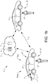
- Figures 1a and 1b schematically show a first vehicle V1 and a second vehicle V2 located in a geographical area G.
- the geographical area G may be any suitable area where the vehicles are located, and the size of the geographical area G may vary, for example depending on the number of vehicles that are located in connection to each other.
- the first vehicle V1 and the second vehicle V2 are configured for communicating with each other, and at least the second vehicle V2 is configured to receive information from the first vehicle V1, either directly or indirectly via a suitable communication protocol.
- Communicating vehicles are well known in the art and it is often referred to vehicle-to-vehicle communication (V2V) or car-to-car communication (C2C).
- V2V vehicle-to-vehicle communication
- C2C car-to-car communication
- a cloud service 3 may instead be used for the communication between the first vehicle V1 and the second vehicle V2, where the cloud service 3 may comprise cloud-based servers 4 and cloud-based databases 5 for the processing of information and for communication, as schematically illustrated in figure 1b .
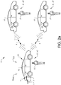
- FIGs 2a and 2b schematically show a plurality of first vehicles V1 and a second vehicle V2 located in the geographical area G.
- a plurality of first vehicles V1 is defined as two or more first vehicles V1.
- two first vehicles V1 are schematically shown for illustrative purposes, but any suitable number of first vehicles V1 may be part of the disclosure, as indicated in figures 7a-b .
- the plurality of first vehicles V1 and the second vehicle V2 are configured for communicating with each other, and at least the second vehicle V2 is configured to receive information from the plurality of first vehicles V1, either directly or indirectly via a suitable communication protocol, such as the V2V communication method or cloud service 3 communication described above, and further illustrated in figures 2a and 2b .
- V2V communication between the first vehicles V1 and the second vehicle V2 is schematically illustrated in figure 2a , and cloud service based communication in figure 2b . It should be understood that some first vehicles V1 may use V2V communication, and some first vehicles V1 cloud based communication, in combination.
- the second vehicle V2 is arranged to communicate with each of the plurality of first vehicles V1, and to receive information from each of the first vehicles V1.
- the first vehicles V1 may be configured to communicate with each other if suitable.
- FIG 7a an example of a geographical area G formed by a parking lot 6 is schematically illustrated, where a plurality of the first vehicles V1 and the second vehicle V2 are parked in the parking lot 6.
- FIG 7b another example of a geographical area G formed by a detached area 7 is schematically illustrated. A plurality of the first vehicles V1 and the second vehicle V2 are parked in the detached area 7. It should be understood that other vehicles than the one or more first vehicles V1 and the second vehicle V2 could be positioned in the same geographical area G.
- a plurality of first vehicles V1 and the second vehicle V2 is shown together with other vehicles VO.
- the disclosure is referring to a method for achieving a desired operational state S DO in a vehicle, where a vehicle component or system is used for achieving the desired operational state S DO .
- the desired operational state S DO may be any state of the vehicle, where a desired result is achieved.
- a desired operational state S DO is a ready to drive state, where a driving activity of the vehicle can be initiated.
- Some procedures are vehicle related and associated with the vehicle.
- Certain vehicle components or systems are configured to detect and monitor the status of the vehicle, and other components or systems need to be activated before a user of the vehicle can drive away with the vehicle.
- the vehicle may for example comprise a control unit that is monitoring the status of the vehicle, vehicle components or systems, and vehicle related activities.
- the control unit is connected to sensors or other components and systems for detecting the status of the components and systems of the vehicle.
- the control unit may be arranged to detect an activation signal of a key fob or other suitable device. In response to the detected signal, the doors are unlocked or locked depending on the signal received.
- the control unit may for example detect that a front vehicle door is opened and that the user of the vehicle is entering a cabin of the vehicle.
- certain vehicle systems may be activated when the vehicle is unlocked or when the ignition is activated.
- Examples of such systems are vehicle safety systems that need to be controlled and activated before the user is driving away with vehicle, and engine systems that need to be activated before the engine is started.
- Vehicle activities that are initiated or activated before driving away with the vehicle is referred to as a preconditioning of the vehicle.
- Other types of systems that need to be activated are for example heating systems in cold climate conditions.
- the control unit may be part of a preconditioning system together with different vehicle components or systems that are initiated, activated, and controlled before the user is allowed to drive away with the vehicle.
- the second vehicle V2 is referred to as the vehicle for which the desired operational state S DO should be achieved.
- the desired operational state S DO of the second vehicle V2 is a ready to drive state, where a driving activity of the second vehicle V2 can be initiated by a user U2 of the second vehicle V2.
- the one or more first vehicles V1 are as described above positioned in the same geographical area G as the second vehicle V2, and the second vehicle V2 can communicate with each of the one or more first vehicles V1.
- the second vehicle V2 is an electric vehicle or a hybrid vehicle, and the second vehicle V2 is connected to a charging station for charging batteries of the second vehicle V2. Any suitable battery charging equipment may be used, and the second vehicle V2 is connected to the charging station via a charging cable 1 and a charging connector 2.
- the charging connector 2 may be arranged in a conventional way with two connectable parts, where a first charging connector part is attached to the second vehicle V2 and second charging connector part to the charging cable 1. In normal conditions, the user U2 of the second vehicle V2 is removing the charging cable before entering and driving away with the vehicle through separating the charging connector parts from each other.
- the one or more first vehicles V1 may be electric vehicles, hybrid vehicles, or traditional vehicles with only internal combustion engines.
- a user U1 of a first vehicle V1 needs to perform a number of vehicle related activities before driving away with the first vehicle V1, such as for example unlocking the vehicle, unplugging the charging cable, entering the vehicle, starting the engine or electric motor.
- the user U1 of the first vehicle V1 may need to perform further vehicle related activities, such as for example remove ice and/or snow from the vehicle, initiate heating of charging connector parts, initiate heating of the vehicle cabin, initiate heating of the battery, and/or initiate heating of vehicle windows.
- These further vehicle related activities may influence the time needed before the user can drive away with the first vehicle V1.
- the time for preparing the first vehicle V1 may be used for indicating a specific condition, such as the exemplified cold climate condition.
- the second vehicle V2 and the first vehicle V1 are positioned in the geographical area G, and the second vehicle V2 is in connection with the first vehicle V1 via suitable communication means, as described above and schematically illustrated in figures 1a and 1b .
- the first vehicle V1 associated with the geographical area G it is possible to measure a first time duration D1 between a first activity A1 of the first vehicle V1 and a second activity A2 of the first vehicle V1.
- the first time duration D1 between the first activity A1 and the second activity A2 is indicative of a time duration for achieving the desired operational state S DO of the second vehicle V2 associated with the geographical area G.
- the first vehicle V1 may be arranged with suitable sensors, components, systems, and control units for detecting the first activity A1 and the second activity A2.
- the first vehicle V1 may also be capable of measuring the first time duration D1 and communicate the first time duration D1, or alternatively communicate the point in time of the first activity A1 and the point in time of the second activity A2.
- the information may be directly communicated to the second vehicle V2, or indirectly via a remote control system such as the cloud service 3. If the point in time of the first activity A1 and the point in time of the second activity A2 are communicated, the second vehicle V2 may calculate the first time duration D1, or alternatively the remote control system may calculate the first time duration D1 and communicate the first time duration D1 to the second vehicle V2.
- the second vehicle V2 and the plurality of first vehicles V1 are positioned in the geographical area G, and the second vehicle V2 is in connection with each of the first vehicles V1 via suitable communication means, as described above and schematically illustrated in figures 2a and 2b .
- the first time duration D1 is determined as an average first time duration D1 of the plurality of first vehicles V1 between a first activity A1 and a second activity A2 of each first vehicle V1.
- the time duration between the first activity A1 and the second activity A2 is measured, and the average value of the measured time durations for the first vehicles V1 is constituting the first time duration D1.
- the time durations between the first activity A1 and the second activity A2 are determined for the two first vehicles V1, and the average value of these two time durations constitutes the first time duration D1.
- the first activity A1 is the same type of activity for all first vehicles V1
- the second activity A2 is the same type of activity for all first vehicles.
- the first time duration D1 between the first activity A1 and the second activity A2, determined as the measured average first time duration D1 for the plurality of first vehicles V1 is indicative of a time duration for achieving the desired operational state S DO of the second vehicle V2 associated with the geographical area G.
- Each of the plurality of first vehicles V1 may be arranged with suitable sensors, components, systems, and control units for detecting the first activity A1 and the second activity A2.
- Each of the plurality of first vehicles V1 may also be capable of measuring the first time duration D1 and communicate the first time duration D1, or alternatively communicate the point in time of the first activity A1 and the point in time of the second activity A2.
- the information may be directly communicated to the second vehicle V2, or indirectly via a remote control system such as the cloud service 3. If the point in time of the first activity A1 and the point in time of the second activity A2 are communicated, the second vehicle V2 may calculate the first time duration D1 as an average value, or alternatively the remote control system may calculate the first time duration D1 as an average value and communicate the first time duration D1 to the second vehicle V2.
- a remote control system such as the cloud service 3.
- the vehicles may be configured with systems that are detecting presence of other vehicles in the same geographical area G.
- the system is communicating the measured or determined first time duration D1 between the first vehicle or vehicles and the second vehicle for an efficient transfer of data.
- the measured or determined first time duration D1 of the one or more first vehicles V1 is communicated from the one or more first vehicles V1 to the second vehicle V2 upon detection of the second vehicle V2, by at least one of the one or more vehicles V1.
- the measured or determined first time duration D1 of the one or more first vehicles V1 is communicated from the one or more first vehicles V1 to the second vehicle V2 upon detection of at least one of the one or more first vehicles V1 by the second vehicle V2.
- the system may be operated to communicate the first time duration D1 from the first vehicle or vehicles V1 to the second vehicle V2 only from each first vehicle V1 being within a pre-determined distance X from the second vehicle V2, as schematically illustrated in figures 1a , 1b , 2a , and 2b .
- the pre-determined distance X is used for limiting the number of vehicles that are communicating with each other, and may differ depending on the number of communicating vehicles within the geographical area G. In this way, only the one or more first vehicles V1 closest to the second vehicle V2 are communicating the first time duration.
- first time duration D1 is greater than a pre-determined time duration value D PRE , a component or system of the second vehicle V2 associated with the desired operational state S DO of the second vehicle V2 is activated.
- the activation of the component or system of the second vehicle V2 associated with the desired operational state S DO is activated before an estimated point in time when the desired operational state S DO of the second vehicle V2 should be achieved.
- the component or system is activated during an activation time duration DA.
- the determined first time duration D1 from the first vehicle or vehicles V1 in the different embodiments is thus used for activating the component or system of the second vehicle V2 if a certain time criterion is met, namely if the first time duration D1 is greater than the pre-determined time duration D PRE .
- the component or system of the second vehicle V2 is associated with the desired operational state S DO , and is activated before an estimated point in time when the desired operational state S DO of the second vehicle should be achieved.
- the second vehicle is thus, based on the input from the first vehicle or vehicles activating the component or system in order to achieve the desired operational state S DO .
- the vehicles are associated with the same geographical area G, and are therefore assumed to have similar external conditions, which may be important for the activation of the component or system, as will be further described below.
- the component or system is activated during an activation time duration DA in order to achieve the desired operational state S DO .
- the pre-determined time duration value D PRE is used as a trigger value for activating the component or system.
- the pre-determined time duration value D PRE may for example be a fixed pre-determined value dependent on the type of component or system, where the pre-determined time duration value D PRE is an estimated value that is typical for the time duration between the first activity A1 and the second activity A2 in normal conditions.
- a suitable pre-determined time duration value D PRE may for example be determined through testing operations or simulations, and may differ between different vehicle types.
- the pre-determined time duration value D PRE is an estimated second time duration D2 associated with the second vehicle V2 between the first activity A1 and the second activity A2 of the second vehicle V2 in normal operational conditions without activation of the component or system, as schematically shown in figure 3b .
- the first activity A1 of the second vehicle V2 is the same as the first activity A1 of the one or more first vehicles V1
- the second activity A2 of the second vehicle V2 is the same as the second activity A2 of the one or more first vehicles V1.
- the estimated second time duration D2 of the second vehicle V2 is suitable to use for the pre-determined time duration D PRE , since it relates to a time duration of the second vehicle between the first activity and the second activity when the component or system is not activated.
- the vehicle could for example be in a standard state and operated in normal conditions where there is no need for activation of the component or system.
- the component or system is activated, the vehicle is in a state deviating from the standard state and operated in specific conditions, such as the cold climate condition, where there is a need for activating the component or system.
- the first activity A1 is a vehicle unlocking activity, or a vehicle user detection activity.
- a vehicle unlocking activity is referring to the unlocking of the vehicle from a locked state.
- the unlocking of the vehicle may be initiated by a user of the vehicle in any suitable way.
- the unlocking can for example be initiated via a key fob or other remote control device associated with the vehicle, a mobile device such as a smartphone associated with the vehicle, a sensor attached to the vehicle, or by a traditional key for unlocking the vehicle.
- a vehicle user detection activity is referring to an event, where an associated user of the vehicle is detected within a certain distance from the vehicle and where the vehicle can detect the user.
- the vehicle user detection activity may be performed with any suitable conventional detection means.
- the detection of the user may be accomplished with a remote vehicle key, a smartphone, or other device detectable by the vehicle within a certain range or distance from the vehicle.
- the detection of the user may also be accomplished with suitable sensors, such as face detection sensors or other suitable sensors.
- the vehicle unlocking or vehicle user detection activities are suitable for starting the measurement of the first time duration D1. Each of these activities may indicate that there is a possible need to activate the component or system for achieving the desired operational state S DO .
- the first activity A1 could be an activity associated with the vehicle different from the ones exemplified above.
- the second activity A2 is a vehicle engine starting activity, a vehicle electric motor starting activity, or a vehicle driving away activity.
- a vehicle engine starting activity is referring to an activity where the user of the vehicle is initiating a starting sequence of an internal combustion engine. The user of the vehicle may for example use a key for starting the engine or push a start button.
- a vehicle electric motor starting activity is referring to an activity where a user of the vehicle is initiating a starting sequence of an electric motor in a hybrid or electric vehicle by for example pushing a start button or activating a start system switch.
- a vehicle driving away activity is referring to an activity where the user of the vehicle is driving away with the vehicle.
- the vehicle driving away activity may for example be determined when the wheels of the vehicle start to rotate, or when a positioning device such as for example a GPS unit, is detecting a movement of the vehicle from a standstill position. Other suitable sensors, such as acceleration sensors may also be used to detect a movement of the vehicle from a standstill position.
- the second activity A2 is an initiation of the activity a first time following an initiation of the first activity A1, and as an example the starting of an engine the first time after unlocking the vehicle may constitute the second activity A2 where the unlocking of the vehicle is the first activity A1.
- the described second activities A2 are suitable for stopping the measurement of the first time duration D1. Each of these activities may indicate that the desired operational state S DO , such as driving away with the vehicle, is achieved. It should be understood that the second activity A2 could be an activity associated with the vehicle different from the ones exemplified above.
- the component or system may be any suitable vehicle component or system.
- the component or system of the second vehicle V2 may be a vehicle heating system H and/or a vehicle preconditioning system PC.
- the vehicle heating system H may be a heating unit of a charging connector part connected to and/or a charging connector part arranged in the second vehicle V2; an engine heating unit arranged in the second vehicle V2; a battery heating unit arranged in the second vehicle V2; and/or a window heating unit arranged in the second vehicle V2.
- the heating systems described are sometimes necessary to activate in order to achieve the desired operational state S DO , such as driving away with the vehicle, and may be activated in specific conditions, such as cold climate conditions.
- the activation time duration DA for the activation of the component or system in the second vehicle V2 may be determined based on a difference between the measured first time duration D1 and the pre-determined time duration value D PRE .
- a high difference between the first time duration D1 and the pre-determined time duration D PRE may be used as an indication for the need of a longer activation time duration DA of the component or the system.
- a low difference between the first time duration D1 and the pre-determined time duration D PRE value may be used as an indication for the need of a shorter activation time duration DA of the component or the system.
- the activation time duration may per se vary depending on the type of component or system being activated, and the activation time duration is based on the difference with for example a specific factor or function.
- a vehicle heating system H may for example be activated in specific conditions during a longer activation time duration DA when the ambient temperature is very low, compared to higher ambient temperatures.
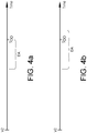
- the desired operational state S DO of the second vehicle V2 is achieved when the activation time duration DA of the component or system is completed, as schematically illustrated in figure 4a , or before the activation time duration DA of the component or system is completed. If the component or system for example is the heating unit of the charging connector part connected to and/or the charging connector part arranged in the second vehicle V2, the heating of the parts should be terminated when the connector parts are separated from each other at a point in time before the user U2 of the second vehicle V2 is driving away with the second vehicle V2. Alternatively, it may be determined that the desired operational state S DO of the second vehicle V2 is achieved before the activation time duration DA of the component or system is completed, as schematically illustrated in figure 4b .
- the component or system is a vehicle heating system H, such as the engine heating unit arranged in the second vehicle V2; the battery heating unit arranged in the second vehicle V2; and/or the window heating unit arranged in the second vehicle V2, it may be desired to operate the heating system H even when driving away with the vehicle.
- a vehicle heating system H such as the engine heating unit arranged in the second vehicle V2; the battery heating unit arranged in the second vehicle V2; and/or the window heating unit arranged in the second vehicle V2
- the activation time duration DA for the activation of the component or system may alternatively, or in addition, be determined based on an environmental condition of the geographical area G.
- the environmental condition could be detected by the first vehicle V1 or first vehicles V1, by the second vehicle V2, and/or by an external detection source.
- the environmental condition could further be estimated by an external estimation source.
- the detected or estimated environmental condition may be a measured or estimated temperature value.
- Temperature sensors arranged in the one or more first vehicles V1 or in the second vehicle V2 could be used for the temperature determination.
- a temperature sensor arranged in the same geographical area G as the one or more first vehicles V1 and the second vehicle V2 can be used for the temperature determination, for example arranged on a suitable building or object.
- Estimated temperature values could for example be collected from weather data sources forecasting weather and temperature conditions of the geographical area G. To avoid that vehicles parked indoors, for example in a garage, are used for the temperature determination, the system may discard measured temperature values that are differing to a high degree compared to other measured temperature values.
- the component or system is activated during the activation time duration DA in order to achieve the desired operational state S DO .
- the degree of activation of the component or system may vary during the activation time duration DA, and the degree of activation may increase, decrease or vary in different ways during the activation time duration DA. If the component or system is the vehicle heating system described above, the vehicle heating system may be activated in different energy modes throughout the activation time duration DA, as exemplified in figures 5a and 5b . In the embodiment illustrated in figure 5a , the component or system of the second vehicle V2 is activated if the first time duration D1 is greater than the pre-determined time duration value D PRE .
- the component or system of the second vehicle V2 is first activated in a low energy mode, where the low energy mode is activated during a first low energy activation time duration D AL1 . Thereafter the component or system is activated in a high energy mode during a first high energy activation time duration D AH1 following the first low energy activation time duration D AL1 . In the embodiment illustrated in figure 5b , the component or system of the second vehicle V2 is activated if the first time duration D1 is greater than the pre-determined time duration value D PRE . The component or system of the second vehicle V2 is first activated in a high energy mode, where the high energy mode is activated during a second high energy activation time duration D AH2 .
- the component or system is activated in a low energy mode during a second low energy activation time duration D AL2 following the second high energy activation time duration D AH2 .
- the activation of the component or system in the low energy mode and the high energy mode is providing an energy efficient solution, without the need for using a high energy mode for longer time periods.
- the estimated point in time for the achieved desired operational state S DO of the second vehicle V2 may be determined in different suitable ways.
- the estimated point in time for the achieved desired operational state S DO of the second vehicle V2 may be selected by a user U2 of the second vehicle V2; or estimated based upon calendar data associated with a user U2 of the second vehicle V2; or estimated based upon historic vehicle usage data of the second vehicle V2.
- the user can in one alternative embodiment, select a suitable point in time for the achievement of the desired operational state S DO .
- the point in time selected by the user is for example an estimated future point in time when the user U2 of the second vehicle V2 is expected to drive away with the second vehicle V2.
- the user U2 may for example communicate the point in time to the second vehicle V2 through a mobile device associated with the vehicle or through a suitable interface in the second vehicle V2.
- the second vehicle is collecting information about the first time duration D1 from one or more second vehicles V1 when such data is available from the one or more first vehicles V1, as described above, to determine if the first time duration D1 is greater than the pre-determined time duration value D PRE .
- the second vehicle is securing that the component or system is activated at a suitable point in time before the desired operational state S DO should be achieved, which suitable point in time for activation of the component or system is depending on the activation time duration DA needed for the system or component before achieving the desired operational state S DO .
- calendar data indicating planned usage of the second vehicle V2 or calendar data indicating specific activities are suitable for determining the point in time for the achieved desired operational state S DO .
- the vehicle may have access to calendar data of the user U2 of the second vehicle V2, and based on the calendar data, the second vehicle V2 is determining the point in time for the desired operational state S DO .
- a further alternative is to use collected information about the vehicle usage to estimate the point in time.
- the second vehicle V2 may be configured to detect when the user U2 of the vehicle usually is driving away with the second vehicle V2, and based on recurring data estimate the point in time for the achieved desired operational state S DO .
- Suitable software algorithms may be used for the time estimations and determinations, and calculations needed may be performed by the control unit.
- a notification may be sent from the second vehicle V2 to a user U2 associated with the second vehicle V2 when the component or system of the second vehicle V2 is activated.
- a notification is sent from the second vehicle V2 to the user U2 associated with the second vehicle V2 when the desired operational state S DO of the second vehicle V2 is achieved, and/or notification is sent from the second vehicle V2 to the user U2 associated with the second vehicle V2 at a pre-determined notification time period T NOT before the desired operational state S DO of the second vehicle V2 is achieved, as schematically illustrated in figure 6 .
- the notifications are making the user aware of the events described.
- the notifications could for example be sent to the user U2 of the second vehicle V2 via the cloud service 3 or directly from the second vehicle V2, and received in a mobile device, such as a smartphone, associated with the user U2 of the second vehicle V2.
- the disclosure further concerns a non-transitory computer-readable medium comprising instructions which, when executed by a computer, cause the computer to carry out the method in the embodiments described above.
- the disclosure further concerns a cloud computing system configured to carry out the method in the embodiments described above.
- a non-transitory computer-readable storage medium storing one or more programs configured to be executed by one or more processors of the vehicle component or system, the one or more programs comprising instructions for performing the method according to any one of the above-discussed embodiments.
- a cloud computing system can be configured to perform any of the method aspects presented herein.
- the cloud computing system may comprise distributed cloud computing resources that jointly perform the method aspects presented herein under control of one or more computer program products.
- the processor may be connected to one or more communication interfaces and/or sensor interfaces for receiving and/transmitting data with external entities such as e.g. sensors arranged on the vehicle surface, an off-site server, or the cloud-based server.
- the processors associated with the vehicle system may be or include any number of hardware components for conducting data or signal processing or for executing computer code stored in memory.
- the system may have an associated memory, and the memory may be one or more devices for storing data and/or computer code for completing or facilitating the various methods described in the present description.
- the memory may include volatile memory or non-volatile memory.
- the memory may include database components, object code components, script components, or any other type of information structure for supporting the various activities of the present description. According to an exemplary embodiment, any distributed or local memory device may be utilized with the systems and methods of this description.
- the memory is communicably connected to the processor (e.g., via a circuit or any other wired, wireless, or network connection) and includes computer code for executing one or more processes described herein.
- step 120 a first time duration D1 between the first activity A1 of the first vehicle V1 and the second activity A2 of the first vehicle V1 is measured, or an average first time duration D1 of the plurality of first vehicles V1 between the first activity A1 and the second activity A2 of each first vehicle V1 is measured.
- step 130 the first time duration D1 measured by the one or more first vehicles V1 is communicated from the one or more first vehicles V1 to the second vehicle V2.
- step 150 a component or system of the second vehicle V2 associated with the desired operational state S DO of the second vehicle V2 is activated during an activation time duration DA if the first time duration D1 is greater than a pre-determined time duration value D PRE , and activation of the component or system of the second vehicle V2 before an estimated point in time when the desired operational state S DO of the second vehicle V2 should be achieved.
- the method for achieving a desired operational state in a vehicle further comprises the following steps: In step 110, the second vehicle V2 is detecting the presence of the one or more first vehicles V1, and/or the one or more first vehicles V1 are detecting the presence of the second vehicle V2.
- step 140 the first time duration D1 is communicated to the second vehicle V2 from each first vehicle or vehicles V1 being within a pre-determined distance X from the second vehicle V2.
- step 160 the component or system of the second vehicle V2 is activated in the low energy mode during the first low energy activation time duration D AL1 and in a high energy mode during the first high energy activation time duration D AH1 following the first low energy activation time duration D AL1 ; or the component or system of the second vehicle V2 is activated in the high energy mode during the second high energy activation time duration D AH2 in the low energy mode during the second low energy activation time duration D AL2 following the second high energy activation time duration D AH2 .
- a notification is sent from the second vehicle V2 to a user U2 associated with the second vehicle V2 when the component or system of the second vehicle V2 is activated; and/or a notification is sent from the second vehicle V2 to the user U2 associated with the second vehicle V2 when the desired operational state S DO of the second vehicle V2 is achieved; and/or a notification is sent from the second vehicle V2 to the user U2 associated with the second vehicle V2 at a pre-determined notification time period T NOT before the desired operational state S DO of the second vehicle (V2) is achieved.
Landscapes
- Engineering & Computer Science (AREA)
- Power Engineering (AREA)
- Transportation (AREA)
- Mechanical Engineering (AREA)
- Electric Propulsion And Braking For Vehicles (AREA)
- Traffic Control Systems (AREA)
Priority Applications (3)
| Application Number | Priority Date | Filing Date | Title |
|---|---|---|---|
| EP20174497.6A EP3909804A1 (fr) | 2020-05-13 | 2020-05-13 | Procédé permettant d'obtenir un état de fonctionnement souhaité dans un véhicule |
| CN202180034035.5A CN115515806A (zh) | 2020-05-13 | 2021-04-22 | 一种用于在车辆中实现期望的操作状态的方法 |
| PCT/CN2021/088944 WO2021227816A1 (fr) | 2020-05-13 | 2021-04-22 | Procédé d'obtention d'état de fonctionnement souhaité dans un véhicule |
Applications Claiming Priority (1)
| Application Number | Priority Date | Filing Date | Title |
|---|---|---|---|
| EP20174497.6A EP3909804A1 (fr) | 2020-05-13 | 2020-05-13 | Procédé permettant d'obtenir un état de fonctionnement souhaité dans un véhicule |
Publications (1)
| Publication Number | Publication Date |
|---|---|
| EP3909804A1 true EP3909804A1 (fr) | 2021-11-17 |
Family
ID=70856995
Family Applications (1)
| Application Number | Title | Priority Date | Filing Date |
|---|---|---|---|
| EP20174497.6A Pending EP3909804A1 (fr) | 2020-05-13 | 2020-05-13 | Procédé permettant d'obtenir un état de fonctionnement souhaité dans un véhicule |
Country Status (3)
| Country | Link |
|---|---|
| EP (1) | EP3909804A1 (fr) |
| CN (1) | CN115515806A (fr) |
| WO (1) | WO2021227816A1 (fr) |
Citations (3)
| Publication number | Priority date | Publication date | Assignee | Title |
|---|---|---|---|---|
| US20150222708A1 (en) * | 2011-01-14 | 2015-08-06 | Cisco Technology, Inc. | System and method for applications management in a networked vehicular environment |
| US20180201151A1 (en) * | 2017-01-18 | 2018-07-19 | Ford Global Technologies, Llc | Battery health evaluation |
| US20200055406A1 (en) * | 2018-08-17 | 2020-02-20 | GM Global Technology Operations LLC | Vehicle rechargeable energy storage system and method of preconditioning the rechargeable energy storage system |
Family Cites Families (11)
| Publication number | Priority date | Publication date | Assignee | Title |
|---|---|---|---|---|
| US4986493A (en) * | 1988-01-05 | 1991-01-22 | Branko Sarh | Convertible fixed wing aircraft |
| JP5078937B2 (ja) * | 2009-03-30 | 2012-11-21 | 株式会社デンソーアイティーラボラトリ | 車両用空調装置及び車両用空調装置の制御方法 |
| EP3481671A4 (fr) * | 2016-07-06 | 2020-08-12 | Ford Global Technologies, LLC | Partage d'informations et amélioration de l'expérience de l'utilisateur par des véhicules sensibles au contexte |
| KR101817442B1 (ko) * | 2016-09-30 | 2018-01-11 | 제주대학교 산학협력단 | 유전 알고리즘을 이용하여 전력 거래를 동적으로 스케줄링하는 방법 및 장치 |
| KR102648814B1 (ko) * | 2016-12-28 | 2024-03-19 | 현대자동차주식회사 | 차량용 자동 환기 시스템 및 그 방법 |
| JP6624084B2 (ja) * | 2017-01-12 | 2019-12-25 | トヨタ自動車株式会社 | 電動車両 |
| CN107639994A (zh) * | 2017-03-17 | 2018-01-30 | 成都雅骏新能源汽车科技股份有限公司 | 一种新能源电动汽车空调远程控制方法 |
| JP6686954B2 (ja) * | 2017-03-28 | 2020-04-22 | 株式会社デンソー | 空調制御システム |
| CN109693506A (zh) * | 2017-10-20 | 2019-04-30 | 郑州宇通客车股份有限公司 | 一种电动汽车及其车内温度调节方法、系统 |
| EP3584106A1 (fr) * | 2018-06-19 | 2019-12-25 | Einride Ab | Gestion thermique à distance prédictive |
| EP3611043B1 (fr) * | 2018-08-17 | 2023-10-18 | Ningbo Geely Automobile Research & Development Co., Ltd. | Système de pré acclimatation |
-
2020
- 2020-05-13 EP EP20174497.6A patent/EP3909804A1/fr active Pending
-
2021
- 2021-04-22 CN CN202180034035.5A patent/CN115515806A/zh active Pending
- 2021-04-22 WO PCT/CN2021/088944 patent/WO2021227816A1/fr not_active Ceased
Patent Citations (3)
| Publication number | Priority date | Publication date | Assignee | Title |
|---|---|---|---|---|
| US20150222708A1 (en) * | 2011-01-14 | 2015-08-06 | Cisco Technology, Inc. | System and method for applications management in a networked vehicular environment |
| US20180201151A1 (en) * | 2017-01-18 | 2018-07-19 | Ford Global Technologies, Llc | Battery health evaluation |
| US20200055406A1 (en) * | 2018-08-17 | 2020-02-20 | GM Global Technology Operations LLC | Vehicle rechargeable energy storage system and method of preconditioning the rechargeable energy storage system |
Also Published As
| Publication number | Publication date |
|---|---|
| CN115515806A (zh) | 2022-12-23 |
| WO2021227816A1 (fr) | 2021-11-18 |
Similar Documents
| Publication | Publication Date | Title |
|---|---|---|
| CN111516640B (zh) | 车门控制方法、车辆、系统、电子设备和存储介质 | |
| CN109799801B (zh) | 无人驾驶运输系统 | |
| US9886800B2 (en) | Engine state detection device | |
| US20180107473A1 (en) | Determining whether to install a vehicle system update in a vehicle | |
| US20200114768A1 (en) | Energy-consumption detection of vehicles in an off state | |
| US10857882B2 (en) | System and method for remotely controlling and monitoring vehicle based on IOT | |
| US20110246025A1 (en) | Vehicle position tracking system | |
| EP3479361B1 (fr) | Dispositifs de communication sans fil | |
| US20190259224A1 (en) | A method for estimating the travel time of a vehicle based on the determination of the state of the vehicle | |
| CN114347950A (zh) | 车辆异常处理方法、车载设备及电子设备 | |
| CN115139983B (zh) | 信息提示的方法、设备及存储介质 | |
| WO2021227816A1 (fr) | Procédé d'obtention d'état de fonctionnement souhaité dans un véhicule | |
| CN112141028B (zh) | 车辆及其控制方法 | |
| CN114666377A (zh) | 车辆的远程控制方法、装置和车辆 | |
| WO2025024584A1 (fr) | Systèmes et procédés de suivi de données de pilote historiquiques en périphérie | |
| US20240132020A1 (en) | Automatic trigger strategy for clearing exterior biometric sensors | |
| CN108337291B (zh) | 车辆远程服务系统和方法、处理装置和存储装置 | |
| CN118172034A (zh) | 服务器 | |
| CN113393696B (zh) | 一种车辆定位系统及其使用方法 | |
| CN112929608A (zh) | 一种油箱监控系统、油箱监控方法、设备及存储介质 | |
| CN113421361A (zh) | 车辆动态搜索钥匙控制方法、车载电子设备、车外电子设备及存储介质 | |
| US20180033218A1 (en) | Remotely connected car internet of things key | |
| WO2022089846A1 (fr) | Procédé de surveillance d'état de santé de batterie d'un véhicule | |
| CN119418424B (zh) | 车辆事故远程识别方法、装置、车辆、设备及存储介质 | |
| US20240220596A1 (en) | Accessory authentication |
Legal Events
| Date | Code | Title | Description |
|---|---|---|---|
| PUAI | Public reference made under article 153(3) epc to a published international application that has entered the european phase |
Free format text: ORIGINAL CODE: 0009012 |
|
| STAA | Information on the status of an ep patent application or granted ep patent |
Free format text: STATUS: REQUEST FOR EXAMINATION WAS MADE |
|
| 17P | Request for examination filed |
Effective date: 20200513 |
|
| AK | Designated contracting states |
Kind code of ref document: A1 Designated state(s): AL AT BE BG CH CY CZ DE DK EE ES FI FR GB GR HR HU IE IS IT LI LT LU LV MC MK MT NL NO PL PT RO RS SE SI SK SM TR |
|
| B565 | Issuance of search results under rule 164(2) epc |
Effective date: 20201112 |