EP3909896A1 - Dispositif de filage et procédé de rattachement d'un fil - Google Patents
Dispositif de filage et procédé de rattachement d'un fil Download PDFInfo
- Publication number
- EP3909896A1 EP3909896A1 EP21172363.0A EP21172363A EP3909896A1 EP 3909896 A1 EP3909896 A1 EP 3909896A1 EP 21172363 A EP21172363 A EP 21172363A EP 3909896 A1 EP3909896 A1 EP 3909896A1
- Authority
- EP
- European Patent Office
- Prior art keywords
- thread
- piecing
- spinning
- feed
- station
- Prior art date
- Legal status (The legal status is an assumption and is not a legal conclusion. Google has not performed a legal analysis and makes no representation as to the accuracy of the status listed.)
- Granted
Links
Images


Classifications
-
- B—PERFORMING OPERATIONS; TRANSPORTING
- B65—CONVEYING; PACKING; STORING; HANDLING THIN OR FILAMENTARY MATERIAL
- B65H—HANDLING THIN OR FILAMENTARY MATERIAL, e.g. SHEETS, WEBS, CABLES
- B65H67/00—Replacing or removing cores, receptacles, or completed packages at paying-out, winding, or depositing stations
- B65H67/04—Arrangements for removing completed take-up packages and or replacing by cores, formers, or empty receptacles at winding or depositing stations; Transferring material between adjacent full and empty take-up elements
- B65H67/0405—Arrangements for removing completed take-up packages or for loading an empty core
- B65H67/0417—Arrangements for removing completed take-up packages or for loading an empty core for loading an empty core
- B65H67/0422—Arrangements for removing completed take-up packages or for loading an empty core for loading an empty core for loading a starter winding, i.e. a spool core with a small length of yarn wound on it; preparing the starter winding
-
- D—TEXTILES; PAPER
- D01—NATURAL OR MAN-MADE THREADS OR FIBRES; SPINNING
- D01H—SPINNING OR TWISTING
- D01H4/00—Open-end spinning machines or arrangements for imparting twist to independently moving fibres separated from slivers; Piecing arrangements therefor; Covering endless core threads with fibres by open-end spinning techniques
- D01H4/48—Piecing arrangements; Control therefor
- D01H4/50—Piecing arrangements; Control therefor for rotor spinning
-
- B—PERFORMING OPERATIONS; TRANSPORTING
- B65—CONVEYING; PACKING; STORING; HANDLING THIN OR FILAMENTARY MATERIAL
- B65H—HANDLING THIN OR FILAMENTARY MATERIAL, e.g. SHEETS, WEBS, CABLES
- B65H65/00—Securing material to cores or formers
-
- D—TEXTILES; PAPER
- D01—NATURAL OR MAN-MADE THREADS OR FIBRES; SPINNING
- D01H—SPINNING OR TWISTING
- D01H15/00—Piecing arrangements ; Automatic end-finding, e.g. by suction and reverse package rotation; Devices for temporarily storing yarn during piecing
-
- D—TEXTILES; PAPER
- D01—NATURAL OR MAN-MADE THREADS OR FIBRES; SPINNING
- D01H—SPINNING OR TWISTING
- D01H4/00—Open-end spinning machines or arrangements for imparting twist to independently moving fibres separated from slivers; Piecing arrangements therefor; Covering endless core threads with fibres by open-end spinning techniques
- D01H4/48—Piecing arrangements; Control therefor
-
- B—PERFORMING OPERATIONS; TRANSPORTING
- B65—CONVEYING; PACKING; STORING; HANDLING THIN OR FILAMENTARY MATERIAL
- B65H—HANDLING THIN OR FILAMENTARY MATERIAL, e.g. SHEETS, WEBS, CABLES
- B65H2701/00—Handled material; Storage means
- B65H2701/30—Handled filamentary material
- B65H2701/31—Textiles threads or artificial strands of filaments
Definitions
- the present invention relates to a spinning device, in particular a rotor spinning device or air-jet spinning device, with a plurality of preferably self-sufficient work stations, each of which has a spinning station for producing a thread and a winding station for winding the thread on a cheese, the winding station having a tube holder for receiving a tube, a
- the winding roller for driving the sleeve or the cheese and a traversing device for laying the thread on the cheese comprises and the spinning station has several individual drives and / or the winding station at least for the winding roller and the traversing device each have a single drive, as well as a method for piecing a thread in a preferably self-sufficient working station of a spinning device with a feed thread which is fed to the spinning station with a handling device for piecing a thread and wherein the spun thread is transferred to an empty tube.
- a textile machine producing cross-wound bobbins which has a large number of similar, largely self-sufficient work stations and open-end spinning devices for the production of yarns, the yarn parameters of which are individually adjustable, as well as a service unit which can be moved along the work stations and is equipped with an auxiliary thread feed device, which has a service unit that Provides empty tube change for piecing the job required auxiliary thread. It is provided that the auxiliary thread delivery device of the service unit is designed to receive at least two supply bobbins with different threads and that one of these threads can be provided by the auxiliary thread delivery device as an auxiliary thread.
- the disadvantage here is that the threads of the pre-winding must be adapted to the threads to be spun. If other threads are to be processed on the textile machine, the supply bobbins must also be replaced. In addition, it must always be ensured that there is a sufficient length of thread on the supply bobbins to be able to carry out the piecing process. Empty, almost empty or incorrect supply bobbins must be replaced. This is maintenance-intensive and can be faulty. In particular in modern spinning machines, in which several different threads can be spun, many different auxiliary threads must be kept in the service unit in order to be able to spin on all the spinning positions.
- the object of the present invention is thus to remedy the above-mentioned disadvantages and to provide a piecing thread suitable for the respective job.
- the object is achieved by a spinning device and a method for piecing a thread in a work station of a spinning device with the features of the independent claims.
- the present invention relates to a spinning device, in particular a rotor spinning device or an air spinning device, with a plurality of preferably self-sufficient work stations, each of which has a spinning station for producing a thread and a winding station for winding the thread on a cheese.
- the winding station comprises a tube holder for receiving a tube or the cheese, a winding roller for driving the tube or the cheese and a traversing device for laying the thread on the tube or the cheese.
- the spinning station and / or the winding station have several individual drives, an individual drive being provided at the winding station at least for the winding roller and the traversing device.
- a sliver is broken up into individual fibers and fed to a rapidly rotating spinning rotor.
- the rotor spinning machine preferably has an individual drive for a feed device for fiber material from a fiber sliver into the work station, for an opening roller for breaking up the fiber material, for the spinning rotor for producing a thread and / or for a withdrawal device for withdrawing the thread from the spinning rotor.
- the fibers are collected in the spinning rotor and drawn off again as a thread.
- the withdrawal takes place with take-off rollers of the take-off device, which convey the thread at a predetermined speed.
- the thread is then fed to the traversing device and guided back and forth in front of the rotating sleeve or cross-wound bobbin and wound onto it.
- a piecing thread or feed thread is held in the rotating spinning rotor and pulled out of the spinning rotor together with the fibers that have accumulated on it.
- a sliver is drawn in a drafting system and the thin sliver obtained is guided through an air-jet nozzle.
- the fibers are twisted by an air vortex and thus form a thread. Similar to rotor spinning, this thread is drawn off with draw-off rollers and, with the help of the traversing device, is wound crosswise onto a tube or onto a cheese.
- a piecing thread is inserted into or through the air-jet nozzle. The fibers drawn in the drafting system are connected to the piecing thread and conveyed and drawn off together through the air-jet nozzle.
- the spinning device is assigned a feed thread device suitable for piecing the thread. This makes it possible to carry out the piecing process without a thread on the bobbin is used. In particular, if there is only one empty tube at the work site, a corresponding feed thread device is required.
- the invention proposes that at least one feed thread device with a feed thread suitable for piecing the thread onto an empty tube is assigned in a stationary manner to each work station, the feed thread being stored independently of the spun thread.
- each work station can start the piecing process on an empty tube without having to wait for a mobile service device.
- the feed thread is present at every work station and can be introduced into the spinning rotor or the air-jet nozzle.
- a feed thread device can be arranged in a service device that patrols along the spinning device and is delivered to the work site for piecing or filling up the feed thread device when required.
- one feed thread device is provided for two adjacent work stations.
- the feed thread device is positioned, for example, centrally between two adjacent workplaces and thus can serve both workplaces with one feed thread.
- the feed thread is stored in the feed thread device independently of the spun thread.
- the feed thread device thus does not correspond to a conventional thread store, which is provided for length compensation between thread production and winding in many spinning devices, but represents an independent device in which one of the feed thread is stored, which is used in particular for piecing onto an empty tube when there is no thread for piecing from the cheese.
- the feed thread is stored independently of the spun thread. This means that the thread does not run through the thread store during normal thread production.
- the thread store is therefore not constantly filled and emptied again, but is only used when a thread is spun, in particular when the thread is to be spun onto a tube without thread winding.
- the feed thread device has a thread store for storing a feed thread with a length for at least one, preferably at least three piecing attempts.
- the thread store is thus able to carry out at least one piecing attempt.
- the length of the feed thread enables several piecing attempts. Only after the feed thread has been used up is it necessary again for the thread store to be filled with another feed thread. This filling can be done, for example, with a mobile service device which patrols along the spinning device and detects when the thread store is no longer sufficiently filled. In this case, the service device can refill the stationary thread store at the work site, for example from an auxiliary spool that is carried along, by unwinding the thread from the auxiliary spool and introducing it into the thread store or winding it up on it.
- the thread store is an auxiliary bobbin or a drum store.
- a particularly simple embodiment of the thread store is an auxiliary spool on which the feed thread is wound and is unwound for piecing if necessary.
- the auxiliary spool can be provided with a drive with which it can be rotated in order to take up the thread, which is supplied, for example, by the mobile service device.
- the mobile service device can also have a device with which the auxiliary spool can be rotated so that it can take over the feed thread.
- the feed thread is wound crosswise on the auxiliary bobbin.
- a corresponding traversing device can be provided, which is either arranged on each feed thread device or is delivered from the mobile service device.
- a drum store can also be provided to accommodate the feed thread. This more complex device is able to take up the feed thread in such a way that it can be unwound again without any problems.
- a drum store is usually self-propelled and causes a parallel or cross-wise laying of the feed thread wound on it.
- a handling device is preferably available at each work station for piecing the thread with the feed thread and for transferring the spun thread to the empty tube.
- the work station is thus self-sufficient in this respect as well, i.e. not dependent on a mobile service device or an operator for piecing.
- a suction device is advantageously provided for sucking off a part of the spun thread at each work site. This makes it possible for the piece of thread which contains the piecer to be sucked off and disposed of via the suction device. This is particular This is advantageous when the piecing thread and the thread to be newly spun are not identical or the piecing does not meet the specified quality criteria, i.e. is too thick or too thin compared to the rest of the thread, for example.
- the preferred spinning device now makes it possible for each work station to independently spin a new thread, even if a bobbin change has previously taken place and there is only an empty tube and no cross-bobbin that has started, from which the piecing thread could be used.
- the work station is assigned a preparation device for preparing the feed thread for the next piecing process, in particular for preparing an end of the feed thread.
- the preparation device can put the feed thread into a state in which it is ideally suited for the next piecing process and can grip the newly spun thread and pull it out of the spinning rotor or through the air-jet nozzle.
- a positioning device for preparing the feed thread for a piecing process is assigned to each work station.
- the positioning device positions the feed thread or the end of the feed thread at a point of the work station at which the feed thread can be reached by a handling device which is assigned to the work station. From there, the feed thread is picked up by this handling device and fed to the spinning station for piecing.
- the spinning station has individual drives for a feed roller, an opening roller, a spinning rotor, a take-off roller and / or a drafting device.
- the spinning position can thus work independently. This means that it can spin a thread independently of other jobs.
- different speeds of rotation of the individual components of the spinning station are required in order to be able to create a successful piecing. This can be carried out particularly well with an autarkic spinning station at which the speeds of the corresponding components can be set individually.
- the spinning device is assigned a movable service device which has a control device for checking the filling level of the thread store.
- the control device can thus determine whether the stationary thread store on the spinning device has stored a sufficient thread length in order to be able to carry out a predetermined number of piecing attempts.
- the service device has a thread supply store, for example an auxiliary bobbin, for filling the stationary thread store with a feed thread.
- the service device can refill the stationary thread store from this thread storage store, which has a longer thread length than the stationary thread store.
- the thread of the thread storage device is used for piecing a thread on the spinning device.
- the movable service device carries a larger amount or length of feed thread and can thus refill the thread store so that the work station can work independently again. This filling of the thread store can take place at times when the thread store is not needed, i.e. during the formation of the cheese, during which there is a pieced thread from the cheese.
- the Feed thread provided by a feed thread device.
- the feed thread is fed with a handling device to the spinning station for piecing a thread and the spun thread is transferred to an empty tube or a cheese.
- the handling device is preferably arranged at the work station so that it can work independently.
- the method according to the invention can, however, also be carried out when the handling device is arranged on a movable service device and is delivered to the work site at which a piecing process is to be carried out.
- the feed thread is stored independently of the spun thread in a feed thread device assigned to the work station in a stationary manner.
- the feed thread device can be arranged at each individual work station. However, it can also be positioned on the spinning device in such a way that it can be used for several jobs.
- the feed thread is either made available for a single job or for neighboring jobs.
- the spinning of a thread onto an empty tube can thus take place independently of the presence of an operator or a mobile service device at the work site. It is therefore possible to work independently at the workplace without waiting times. The efficiency of the job can thus be increased significantly.
- a feed thread with a length for at least one, preferably at least three piecing attempts is stored in the feed thread device. It is thus possible for at least one piecing attempt, preferably several piecing attempts, to be carried out before the feed thread device has to be refilled with a feed thread.
- a handling device is assigned to each work station, with which the feed thread for piecing the thread is introduced into the spinning station and the spun thread is transferred to the empty tube.
- the handling device which is assigned to each work station, can either be arranged at each individual work station or be positioned so that it can reach several work stations.
- the handling device enables independent piecing at every job it can reach.
- the feed thread stored in the feed thread device can thus be used for the piecing process.
- a suction device assigned to each work station.
- a suitable suction device is advantageous.
- the continuously produced thread is preferably sucked off in the suction device until the work on winding the thread onto the empty tube has been completed and the normal traversing of the thread for winding onto a cheese has begun.
- the feed thread is prepared for the next piecing process with a preparation device assigned to each work station.
- the thread for piecing here the feed thread
- a preparation of the thread end for example by thinning or roughening, can be advantageous.
- the preparation of the end of the feed thread for the next piecing process is carried out mechanically, pneumatically, electrically and / or chemically.
- the feed thread can be cut, for example, using scissors and / or prepared and cleaned using brushes. Blasts of air or air swirls can also be suitable for preparing the feed thread.
- the feed thread can be prepared electrically, for example, in that the end of the feed thread is thermally cleaned. Chemical substances that remove the impurities can also be used to prepare the end of the feed thread for the next piecing process.
- the surface structure of the feed thread is changed depending on the thread to be spun. The surface structure can have a particular influence on the success of piecing. A more or less coarse or rough or hairy surface structure can be more suitable for binding the fibers of the newly spun thread to the feed thread than a particularly smooth surface structure. Depending on the thread to be spun, certain surface structures can, however, be more or less advantageous.
- the feed thread is positioned for a piecing process with a positioning device which is assigned to each work station.
- the feed thread can be held by the positioning device in a position in which it can be easily gripped by a handling device at the work station and used to apply a new thread.
- the positioning device can provide that a certain length of the feed thread protrudes beyond a predetermined clamping point in order to make a correct length of the feed thread available for piecing. In this case, the handling device no longer has to correct the length of the feed thread in order to be able to achieve piecing.
- a feed roller, an opening roller, a spinning rotor, a take-off roller and / or a drafting device of each spinning station are driven with individual drives.
- the spinning station advantageously has several individual drives and / or the winding station has at least one individual drive for at least the winding roller and the traversing device.
- the individual drives can be different.
- a rotor spinning machine for example, a single drive can be provided for the feed roller, the opening roller, the rotor drive and the take-off rollers.
- individual drives can be provided for the drafting system and the take-off rollers, for example. The more of these elements are equipped with a single drive, the more self-sufficient the job can work.
- the filling level of the thread store is checked with a service device that can be moved along the spinning device and / or the thread store is filled with a feed thread. After the thread store takes up a limited amount of the feed thread, it must be checked whether the thread store is sufficiently full for the next piecing process or processes. This can advantageously be done by the service device which patrols along the spinning device.
- the service device preferably not only signals when the thread store needs to be replenished, but is also able to refill the thread store, especially if the length of the feed thread stored in the thread store is no longer sufficient for a predetermined number of piecing attempts.
- the service device carries, for example, an auxiliary bobbin with a large amount of the feed thread and, if necessary, rewinds it into the local thread store.
- the service device can also carry several pre-wound thread stores and exchange the empty, local thread store for one of the pre-wound thread stores carried along.
- the thread store is filled with a feed thread from the spinning station or from the cheese.
- the thread newly spun in the spinning station is diverted into the thread store and there the thread store is wound with the newly spun thread until a length is available which is sufficient for a predetermined number of piecing attempts.
- a thread that has already been spun is unwound from the cross-wound bobbin at the job site, in particular before it is exchanged for a new tube, and stored in the thread store.
- the feed thread is taken over from a thread supply store, for example an auxiliary bobbin, of the movable service device and is either spun directly or the thread store is first filled up and then spun.
- a thread supply store for example an auxiliary bobbin
- the stationary thread store and / or the thread store store is replenished. This means that the thread store and / or the thread storage store are available again for the next piecing or filling of the thread store.
- the spinning device can alternatively have at least one feed thread device with a feed thread suitable for piecing the thread.
- the feed thread be a piecing member that can be reused for several piecing processes so that a separate supply bobbin does not have to be kept available at each work station for each thread to be pieced on, or the filling level of each supply spool does not have to be monitored is.
- this piecing thread is either wound onto the cheese or is sucked off via the suction system, the reusable piecing element can be used several times for piecing. There is thus no or at least little consumption of the piecing element. Even if the piecing element is consumed, it is so small that the piecing element can be used for a large number of piecing attempts.
- the piecing element can be kept ready, for example, in a spool which takes up a length of, for example, 1 to 10 meters of the piecing element. Due to the very low consumption, this length is then sufficient for a large number of piecing attempts. It is therefore not necessary to store a large bobbin on which a conventional piecing thread is wound. It is sufficient that the piecing element is present at the work site and can be inserted into the spinning rotor or the air spinning nozzle. The piecing element is then pulled out again, together with the newly formed thread, from the spinning rotor or the air spinning nozzle and then separated again from the newly formed thread. The newly formed thread can now be fed to the tube or cheese. The reusable piecing element is thus available for the next piecing process.
- the piecing element which can be reused for several piecing processes is preferably arranged at each work station and / or in a service device. If the reusable piecing element is arranged at each work station, each work station can start the piecing process on an empty tube without having to wait for a mobile service device. In this case, the feed thread is present at every work station and can be introduced into the spinning rotor or the air-jet nozzle. Additionally or alternatively, the reusable piecing element is arranged in a service device that patrols along the spinning device and is delivered to the work site for piecing if necessary.
- the spinning station advantageously has several individual drives and / or the winding station has at least one individual drive for at least the winding roller and the traversing device.
- the individual drives can be different.
- a single drive can be provided for the feed roller, the opening roller, the rotor drive and the take-off rollers.
- individual drives for example for the drafting device and the take-off rollers, can be provided. The more of these elements are equipped with a single drive, the more self-sufficient the job can work.
- a handling device for piecing the thread with the feed thread and for transferring the spun thread to the empty tube is preferably available at each work station.
- the work station is thus self-sufficient in this respect as well, i.e. not dependent on a mobile service device or an operator for piecing.
- a suction device is advantageously provided for sucking off a part of the spun thread at each work site. This makes it possible for the piece of thread which contains the attachments to be sucked off and disposed of via the suction device. This is particularly advantageous when the piecing thread and the thread to be newly spun are not identical or the piecing does not meet the specified quality criteria, i.e. is too thick or too thin compared to the rest of the thread, for example.
- the preferred spinning device now makes it possible for each work station to independently spin a new thread, even if a bobbin change has previously taken place and only an empty one Tube and no started cheese is present from which the piecing thread could be used.
- the work station is assigned a preparation device for preparing the piecing element for the next piecing process, in particular for cleaning and / or for severing one end of the piecing element.
- a preparation device for preparing the piecing element for the next piecing process, in particular for cleaning and / or for severing one end of the piecing element.
- the piecing element can be returned to a state in which it is ideally suited for the next piecing process and can grasp the newly spun thread and pull it out of the spinning rotor or through the air-jet nozzle.
- the feed thread is provided by a feed thread device.
- the feed thread is fed with a handling device to the spinning station for piecing a thread and the spun thread is transferred to an empty tube or a cheese.
- the feed thread device and / or the handling device are preferably arranged at the work station so that it can work independently.
- the method according to the invention can, however, also be carried out when the feed thread device and / or the handling device is arranged on a movable service device and is delivered to the work site at which a piecing process is to be carried out.
- a piecing element that can be reused for several piecing processes is used as the feed thread.
- This reusable piecing element is not used up like a conventional piecing thread. Accordingly, it is also not necessary to keep a bobbin with a suitable piecing thread in stock.
- the spinning organ is used several times. After a In the piecing process, it is preferably kept ready at the work site, but possibly also at the movable service device, in order to be available for the next piecing process.
- the piecing element can preferably be used universally, ie suitable for attachment to different types of yarns. Since it is not wound onto the tube or cheese, it does not have to correspond to the quality of the spun thread. It only has to be suitable for pulling the newly spun thread from the spinning rotor or through the air-jet nozzle.
- the piecing element is separated from the newly spun, attached thread after attachment.
- the new, spun thread is wound onto the tube or cross-wound bobbin or sucked off by a suction device and the piecing element is available again for the next piecing process.
- the piecing element is prepared for reuse, in particular cleaned, after it has been separated from the attached thread.
- it is brought back into a state in which it is ideally suited for the next piecing process. In this case, fibers or thread remnants of the newly spun thread are removed from the spinning member, in particular from the previous piecing process.
- the preparation of the end of the piecing element for the next piecing process is carried out mechanically, pneumatically, electrically and / or chemically.
- the piecing element can be prepared and cleaned, for example, by means of brushes. Blasts of air or air eddies can also be suitable for preparing the piecing organ.
- the piecing element can be prepared electrically, for example, in that the impurities are thermally cleaned or components of the piecing element, for example filaments, are set in a cleaning movement with an electric drive. Also through chemical substances which remove the impurities, the end of the piecing element can be suitably prepared for the next piecing process.
- the end of the piecing element can be separated, for example cut off or broken off, from the rest of the piecing element, for example mechanically, before the next piecing process.
- This provides a new end of the piecing element for the next piecing process. It is sufficient that only a short piece of the piecing organ is severed.
- the piecing element wound on a bobbin for example, can thus be used for a large number of piecing attempts until it is used up. Then it can be exchanged for a spool with a new piecing element.
- the surface structure of the piecing element is changed depending on the thread to be spun on.
- the surface structure can have a particular influence on the success of piecing.
- a more or less coarse or rough surface structure can be more suitable for binding the fibers of the newly spun thread to the spinning organ than a particularly smooth surface structure.
- certain surface structures can, however, be more or less advantageous.
- a feed thread according to the invention for piecing a thread in a work station of a spinning device is a piecing member that can be reused for several piecing processes.
- the reusable piecing element unlike known piecing threads, is not a consumable item, but can, if necessary after appropriate reprocessing, be used repeatedly to attach a new thread in the spinning device.
- the piecing element is subject to low consumption at most.
- a supply bobbin with many hundreds of meters of thread is not required for re-spinning a new thread.
- the spinning organ can do one Similar to thread, but can also have a different consistency.
- the piecing element has a strength which is higher than the thread to be spun, for which the piecing element is predetermined. This ensures that the piecing element is more stable than the new thread to be spun and that, if the load is too high, the thread breaks first and not the piecing element. The piecing element is thus protected from breakage and can be used for a long time, in particular for a large number of attachment attempts.
- the piecing element is a filament, in particular a multifilament.
- the filament or multifilament is stable and resistant. It can for example consist of aramid, carbon fibers, polyethylene, HPPE, polyamide, polyester or polypropylene and can also be equipped to obtain certain surface properties. It can also be twisted or twisted, for example, in order to improve the piecing properties.
- the piecing element has a rough surface structure for the fibers of the thread to adhere to the piecing element.
- This rough surface structure can be produced, for example, by machining the surface of the piecing element.
- the static friction of the fibers of the new thread to be spun on is so great that the thread can be reliably withdrawn from the spinning rotor or the air-jet nozzle.
- the piecing element has a smooth surface structure for loosening fibers of the thread from the piecing element.
- the surface structure of the spinning organ is smooth in order to clean the piecing organ, especially of fibers and thread residues can.
- the piecing element is designed in such a way that it can assume different surface structures. With one surface structure, fibers adhere very easily to the piecing element in order to be able to pull off the fibers and thus the newly spun thread from the spinning means, i.e. the spinning rotor or the air-jet nozzle. In the case of the other surface structure, the surface is smooth, so that fibers do not easily adhere to the spinning organ and can easily be detached from it again.
- the surface structure of the piecing element can be changed, in particular mechanically, pneumatically, electrically and / or chemically.
- the piecing element can thus be adapted to the specific conditions of the thread to be pieced.
- the surface structure of the piecing organ has protruding and / or abutting ends of fibers of the piecing organ.
- Protruding ends of fibers of the piecing organ create a rough surface to which the fibers of the thread to be spun adhere well.
- Adjacent ends of fibers of the piecing organ allow a smoother surface which is easy to clean. Due to a variable surface structure, which can be influenced by the more or less contact of the ends of the fibers of the spinning organ on the spinning organ, the spinning organ is able to be optimally adapted for both the piecing and cleaning.
- the piecing organ can thereby be better adapted to the piecing of different new threads, which may differ, for example in material or in thread thickness.
- a length of the protruding fibers of the piecing element can be changed mechanically, electrically and / or chemically.
- the length of the protruding fibers in turn influences the surface roughness of the piecing element and thus the properties for piecing and cleaning the piecing element.
- the length of protruding fiber ends can be changed, for example by wrapping the piecing element to a greater or lesser extent. They can also be applied to the piecing organ to a greater or lesser extent by chemical additives or electrical charges and fixed there permanently or temporarily.
- the piecing element is hollow and has openings from which ends of fibers of the piecing element protrude. Because the fibers protrude more or less long from the hollow piecing organ, a different surface of the piecing organ is generated, which can be adapted to the different threads to be pieced. In particular, if the length of the ends which protrude from the piecing element can be changed, the surface of the piecing element is particularly suitable for piecing on the one hand and particularly suitable for cleaning on the other.
- the ends of the fibers of the piecing element protrude from the piecing element in the manner of a tuft.
- a tuft can be particularly suitable to facilitate piecing.
- the fibers of the new thread to be spun combine with the tuft and can thus be easily withdrawn from the spinning rotor or the air-jet nozzle.
- the spinning device and the method are designed according to the preceding description, it being possible for the features mentioned to be present individually or in any combination.
- FIG 1 is a side view of a spinning device 1 with a plurality of work stations 2 (referred to as work stations 2a to 2h). For the sake of clarity, most of the reference symbols are only identified at work points 2a or 2g.
- Each work station 2 has a spinning station 3 and a winding station 4.
- a thread 5 is produced in the spinning station 3 and wound onto a cheese 6 in the winding station 4.
- the cheese 6 is located on a sleeve 7 which is held in a sleeve holder 8.
- the tube 7 or the cheese 6 are rotated by means of a winding roller 9 on which the cheese 6 or tube 7 rests.
- the thread 5 is moved back and forth with a traversing device 10, which is arranged in front of the winding roller 9 or the sleeve 7 or cross-wound bobbin 6, and is thus wound crosswise on the sleeve 7.
- the spinning station 3 is sketched as a work station of a rotor spinning device.
- a sliver 12 runs from a can 11 into the spinning station 3 with the aid of a rotating feed roller 13.
- the fiber sliver 12 is broken up into individual fibers by an opening roller 14, which fibers are fed through a feed channel 15 to a spinning rotor 16 will.
- the thread 5 is drawn off from the spinning rotor 16 by means of draw-off rollers 17.
- the jobs 2 shown here work independently. At least some, preferably all, drives for the feed roller 13, the opening roller 14, the spinning rotor 16, the take-off roller 17, the winding roller 9 and the traversing device 10 have their own drive. In this way, the individual work stations 2 can work individually and independently of one another and even produce different threads 5.
- a service device 20 is nevertheless provided, which can move back and forth along the spinning device 1 according to the double arrow.
- the service device 20 can support the individual work stations 2 if they have a fault that they cannot correct themselves.
- the service device 20 is often also provided so that a cross-wound bobbin 6, which is sufficiently filled, is exchanged for an empty tube 7.
- a feed thread device 22 is arranged at each work station 2.
- a feed thread 23 is arranged.
- the feed thread device 22 is assigned a preparation device 24 which can prepare the feed thread 23 for error-free use of the feed thread 23.
- a rotor spinning device is usually pieced in that one end of a thread 5 is inserted into the rotating spinning rotor 16. Fibers from the sliver 12 are located in the spinning rotor 16 and have collected in a ring shape in a groove in the spinning rotor 16. The thread end introduced into the spinning rotor 16 tears open the fiber ring, binds its fibers to itself and is withdrawn again from the spinning rotor 16 together with these fibers, which form a new thread 5. The thread end is usually pulled off the cheese 6 and used for attachment. When changing the bobbin, however, there is no longer a cross-wound bobbin 6 in the tube holder 8, but an empty tube 7. Accordingly, there is no thread end for attaching a new thread 5. According to the invention, instead of each work station 2, at least the feed thread device 22 with that for piecing the thread 5 is placed on one Empty tube 7 associated with suitable feed thread 23 in a stationary manner, the feed thread 23 being stored independently of the spun thread 5.
- the feed thread device 22 has a thread store 32, which is shown in the form of a conical bobbin. In this thread store 32 there is a feed thread 23 with a length which is sufficient for at least one piecing process.
- the feed thread 23 is located in feed rollers 33.
- the feed rollers 33 can pull off the feed thread 23 from the thread store 32 so that a defined length is available for piecing at the spinning station 3.
- the thread end of the feed thread 23 lies in the area of a preparation device 24.
- the preparation device 24 can, if necessary, cut the feed thread 23 and, in particular, prepare it for a piecing process.
- the gripping arm 26 pivots from its starting position into an area near the feed rollers 32 and grips the feeder thread 23.
- the feeder rollers 32 simultaneously form a positioning device 36 in which the feeder thread is positioned with its thread end, so that the gripping arm 26 can grip the feed thread 23 in a defined manner.
- the gripping arm 26 introduces the thread end of the feed thread 23 into the spinning station 3.
- the thread end of the feed thread 23 is inserted into the spinning rotor 16.
- the feed thread 23 can be inserted between the take-off rollers 17 so that it can be drawn off quickly from the spinning rotor 16 after piecing.
- the feed thread 23 or later the new thread 5 is sucked in and temporarily stored in a suction tube 25.
- the newly spun thread 5 is gripped by the gripping arm 26 of the handling device 27 and brought into the area of the sleeve 7 with the winding roller 9 and the traversing device 10, for example with a pivoting movement. There the thread 5 is grasped by the sleeve 7 and wound up to form a cross-wound bobbin 6.
- connection between the feed thread 23 and the new thread 5 is separated after the thread 5 has been sucked into the suction tube 25. This is preferably done by cutting off or tearing off the thread 5 from the feed thread 23. This can be done, for example, by a separating device at the work station 2 or on the gripping arm 26.
- the new thread 5 can now be wound onto the cross-wound bobbin 6, as shown in the work stations 2e to 2h.
- the feed thread 23 In order to make the feed thread 23 usable for the next piecing, it is preferably prepared by the preparation device 24. This can be done mechanically, for example with scissors or with brushes, or pneumatically with an air jet, or electrically or chemically. It is important that the feed thread 23 has a thread end with which the next piecing can be carried out as error-free as possible.
- the service device 20 has, in addition to other handling elements required for the activities of the service device 20, also an additional feed thread device 22 '.
- the feed thread device 22 ' serves as a reserve in the event that a work station 2 has a non-functional feed thread device 22 or that the thread store 32 does not have a sufficient length of the feed thread 23 for one or more piecing processes.
- a new thread 5 can be pieced onto an empty tube 7 with the aid of the service device 20.
- the service device 20 is positioned at the respective work station 2 and the feed thread 23 is rewound from a thread supply store, here an auxiliary bobbin 35, onto the thread store 32.
- the thread store 32 then again has a sufficient length of the feed thread 23 so that the work station 2 is again able to independently carry out a piecing process onto an empty tube 7.
- the service device 20 or the work station 2 can be equipped with a sensor of a control device 42, which can detect the current length of the feed thread 23 in the thread store 32.
- a single feed thread device 22 is provided for two adjacent work stations 2.
- the gripping arm 26 is designed in such a way that it can reach both neighboring work stations 2, it is sufficient to have a feed thread device 22 for the two neighboring work stations 2.
- the feed thread device 22 is preferably positioned centrally between two adjacent work stations 2 and can thus serve both work stations 2 with one feed thread 23.
- FIG. 13 is a feed thread device 22 on a rotor spinning device according to FIG Figure 1 shown in more detail. It can be seen from this that the feed thread 23, starting from the feed thread device 22, enters a groove 28 of the spinning rotor 16 is introduced.
- the spinning rotor 16 is provided with a rotor drive 29 and rotates very quickly.
- the piecing thread 23 comes into contact with a ring of fibers located therein.
- this fiber ring is torn open from the groove 28 in the direction of the double arrow and is moved out of the spinning rotor 16 as thread 5.
- the feed thread 23 stored in the thread store 32 is fed to the conveyor rollers 33 via a deflector 38.
- the preparation device 24 with which the thread end of the feed thread 23 can be prepared for the next piecing process.
- the thread store 32 has a drive 37. With the drive 37, the thread store 32 can be set in rotation. This enables the feed thread device 22 ′ of the service device 20 to rewind the feed thread 23 from the auxiliary bobbin 35 onto the thread store 32.
- the feed thread 23 can thus be wound onto the thread store 32 in parallel or crosswise windings. This ensures that when the feed thread 23 is unwound again from the thread store 32, the feed thread 23 does not get tangled.
- FIG 3 shows a feed thread device 22 on an air-jet spinning device.
- the spinning station 3 off Figure 1 is in this case not a rotor spinning device, but an air spinning device with an air spinning nozzle 30.
- the sliver 12 is drawn by a drafting device 31 and fed to the air spinning nozzle 30.
- the feed thread 23 is passed through the air-jet nozzle 30 in the direction of the double arrow, contacts the sliver 12 running out of the drafting system 31 and pulls it through the air-jet nozzle 30 with a backward movement so that it can be sucked off in the suction tube 25 and moved from there to a sleeve 7.
- the feed thread device 22 is constructed in the same way as in the rotor spinning device according to FIG Figure 2 .
- FIG 4 shows a feed thread device 22 with a thread store 32 designed as a drum store 40 on a rotor spinning device.
- the drum storage 40 is driven by the drive 37 and takes up a predetermined length of the feed thread 23. If necessary, the feed thread 23 is removed from the drum storage 40 and fed to the spinning station 3, here the rotor spinning device, via the deflection 38, as already described in the previous exemplary embodiments. In the drum storage 40, the feed thread 23 is taken up in parallel windings so that it can be withdrawn from the drum storage 40 without tangling.
- the drum storage 40 is filled with the thread 5 which was spun by the spinning station 3, here the rotor spinning device.
- the thread 5 is fed from the suction tube 25 and via a deflection 41 to the drum storage 40.
- a separating device not shown here, which can be the preparation device 24, for example, and can be fed to the cross-wound bobbin 6 with the further spinning process.
- the thread 5 is not fed from the rotor spinning device or air-jet spinning device to the thread store 32 immediately after spinning, but that the thread 5, which has already been wound on the cross-wound bobbin 6, is unwound from it and used to fill the Thread store 32 is used.
- the thread 5 can also be fed to the thread store 32, in particular the drum store 40, via deflections and with handling devices and is correspondingly cut off as soon as the thread store 32 is sufficiently full. Then the thread end belonging to the cheese 6 is used for re-spinning in the rotor spinning device or it is removed from the work station 2 together with the cheese 6.
- the empty tube 7 used instead of the removed cheese 6 can now be wound again with a thread 5 which has been spun with the feed thread 23.
- the thread store 32 is filled by the auxiliary bobbin 35 of the service device 20.
- the drum storage 40 is wound with parallel layers of thread.
- the service device 20 can fill a large number of thread stores 32 of the individual work stations 2 due to the large supply of thread in the auxiliary bobbin 35.
- FIG 5 shows similar to the Figure 4 a feed thread device 22 at a work station 2 ( Figure 1 ) a rotor spinning device with a spinning rotor 16 and a drum storage 40 as a thread storage 32.
- a movable service device 20 (not shown) ( Figure 1 ) with an auxiliary bobbin 35 as a thread store.
- the feed thread 23 stored on the auxiliary spool 35 can fill the drum storage 40 with feed thread 23 (in the direction of the arrow) according to the dashed line if it no longer has enough feed thread 23 stored to be able to carry out the predetermined number of piecing processes.
- the drum storage 40 is filled with sufficient feed thread 23 in order to be able to feed the feed thread 23 according to the solid line in the direction of the arrow to the spinning device for the next piecing processes.
- the feed thread 23 can also be fed directly to the conveyor rollers 33 and the preparation device 24 in the direction of the arrow.
- the feed thread 23 coming directly from the auxiliary bobbin 35 is used for piecing a new thread 5 into the spinning rotor 16.
- a further feed thread device 22 is shown on a rotor spinning device with a thread supply store or an auxiliary bobbin 35.
- a further feed thread device 22 is shown on a rotor spinning device with a thread supply store or an auxiliary bobbin 35.
- the movable service device 20 in front of the work station 2 of the rotor spinning device.
- the thread 5 is unwound from the cross-wound bobbin 6 held in a tube holder 8 and the auxiliary bobbin 35 is filled with the thread 5 in the direction of the arrow, so that the auxiliary bobbin 35 has enough thread 5, which is used as a feed thread 23 for the individual workplaces 2 or thread store 32 can be made available.
- thread 5 is shown with a solid line and is guided into the thread store 32 in the direction of the arrow.
- This makes it possible for the thread store 32 from the cheese 6, for example shortly before it is exchanged for a new tube 7, to be filled with thread 5, which can be used as a feed thread 23 for piecing a new thread 5 in the spinning rotor 16 .
- it is always ensured that there is enough feed thread 23 in the thread store 32 after the bobbin change to produce a to be able to carry out a predetermined number of piecing attempts.
- the filling of the thread store 32 can thus take place independently of the presence of the movable service device 20 at the work station 2.
- the thread 5, which was spun in the spinning rotor 16 is temporarily fed directly to the auxiliary bobbin 35 instead of the cross-wound bobbin 6. This is shown with a double-dotted-dashed line. It is thus possible for the auxiliary bobbin 35 to be filled with the thread 5 from the spinning rotor 16 in order to have 2 feed thread 23 available at other work stations.
- FIG. 11 is a side view of a spinning device 1 with a plurality of work stations 2, similar to FIG Figure 1 shown.
- a bobbin is changed, there is no longer a cross-wound bobbin 6 in the tube holder 8, but an empty tube 7. Accordingly, there is no thread end for attaching a new thread 5. Instead, the feed thread device 22 with the piecing element 43 is used.
- the piecing element 43 is a generally flexible, elongated element which can be introduced into the spinning rotor 16, where it connects to the fibers of the fiber ring, tears it open and is then pulled off again.
- the new thread 5 is then sucked into a suction tube 25.
- the thread 5 is then gripped by a gripping arm 26 of a handling device 27 and brought into the region of the tube 7 with the winding roller 9 and the traversing device 10, for example with a pivoting movement. There the thread is grasped by the sleeve 7 and wound up into a cheese.
- the connection between the piecing element 43 and the new thread 5 is separated after the thread 5 has been sucked into the suction tube 25. This is preferably done by cutting off or tearing off the thread 5 from the piecing element 43.
- the piecing element 43 can, for example after piecing, be wound onto a roll of the feed thread device 22 in a space-saving manner and can be unwound from it again for piecing. In order to make the piecing element 43 ready for use for the next piecing, it is preferably prepared by a preparation device 24.
- the piecing element 43 is cleaned of fibers and thread residues. This can be done mechanically, for example with brushes, or pneumatically with an air jet, or electrically or chemically. It is important here that the piecing element 43 is largely returned to its original state so that the next piecing can be carried out as error-free as possible. In addition, it is particularly advantageous if the preparation of the piecing element 43 takes place without or with only very little wear on the piecing element 43, so that the piecing element 43 can be used very frequently.
- the service device 20 has, in addition to other handling elements required for the activities of the service device 20, also an additional feed thread device 22 '.
- the feed thread device 22 ′ serves as a reserve in the event that a work station 2 has a feed thread device 22 that is not functioning. In this case, a new thread 5 can be pieced onto an empty tube 7 with the aid of the service device 20.
- a conventional feed thread bobbin with a thread 5 it is also possible here for a conventional feed thread bobbin with a thread 5 to be arranged instead of the piecing element 43 in order to carry out a conventional attachment with an auxiliary thread.
- the work stations do not have any feed thread devices 22 and only the service device 20 has a feed thread device 22 ′.
- Such a solution also has advantages over the prior art, in which the service device 20 has an original spool that is always full must be present. For piecing, the service device 20 must be positioned at the respective work site and the piecing process must be carried out.
- FIG. 13 is a feed thread device 22 on a rotor spinning device according to FIG Figure 1 shown in more detail. It can be seen from this that the piecing element 43 is introduced from the feed thread device 22 into a groove 28 of the spinning rotor 16.
- the spinning rotor 16 is provided with a rotor drive 29 and rotates very quickly.
- the piecing element 43 comes into contact with a ring of fibers located therein. When the piecing element 43 is rapidly pulled out of the groove 28 in the direction of the double arrow, this fiber ring is torn open and moved out of the spinning rotor 16 as a thread 5.
- Figure 8b shows a feed thread device 22 on an air-jet spinning device.
- the spinning station 3 off Figure 1 is in this case not a rotor spinning device, but an air spinning device with an air spinning nozzle 30.
- the sliver 12 is drawn by a drafting device 31 and fed to the air spinning nozzle 30.
- the piecing element 43 is passed through the air spinning nozzle 30 in the direction of the arrow, contacts the sliver 12 running out of the drafting system 31 and pulls it through the air spinning nozzle 30 with a backward movement in the direction of the double arrow, so that it is sucked off in the suction tube 25 and from there it can be moved further to a sleeve 7.
- the piecing element 43 it is not always necessary for the piecing element 43 to be passed completely through the air spinning nozzle 30.
- the connection between the sliver 12 and the piecing element 43 can also take place within the air-spinning nozzle 30.
- Figure 9a shows a piecing element 43 which is designed as a multifilament 44.
- Several individual filaments 45 lie largely parallel to one another, are flexible and can therefore easily be introduced into the spinning rotor 16 or the air spinning nozzle 30 and withdrawn again.
- the fibers of the new thread 5 can adhere to the end of the multifilament 44 shown on the right and be drawn out of the spinning rotor 16 or through the air-jet nozzle 30.
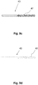
- Figure 9b shows a piecing element 43 with a braided multifilament 46. Due to the non-parallel filaments 45, the fibers 5 can adhere better to the piecing element 43, depending on the thread 5 to be spun on.
- a piecing element 43 with a rough surface 47 is shown sketched.
- the piecing element 43 is an elongated element, for example an elastic plastic rod, on which at least the end is roughened.
- This rough surface 47 in turn enables the fibers of the thread 5 to adhere easily to the piecing element 43 and thus enables the thread 5 to be reliably drawn off from the spinning rotor 16 or through the air-jet nozzle 30.
- Figure 9d shows a piecing element 43 with protruding fiber ends 48.
- the protruding fiber ends 48 which can be designed like stubble, also offer a good surface for the fibers of the thread 5 to attack Withdrawal of the thread 5 from the spinning rotor 16 or through the air-jet nozzle 30.
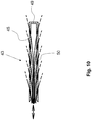
- a piecing element 43 is sketched as a hollow body 49 with filaments 45.
- the hollow body 37 can be an elastic element which is flexible enough to be inserted into the spinning rotor 16 into the groove 28 or through the air-jet nozzle 30 and withdrawn again.
- Filaments 45 are guided in the hollow body 49.
- the hollow body 49 has openings 50 through which the filaments 45 protrude. They thus form, similar to the execution according to Figure 3d , a tuft to which the fibers of the thread 5 can adhere well.
- the filaments 45 can protrude more or less far from the hollow body 49 due to a relative movement according to the double arrow. The length of the protruding ends of the filaments 45 can thus be varied.
- the present invention is not limited to the illustrated and described exemplary embodiments. Modifications within the scope of the claims are just as possible as a combination of the features, even if these are shown and described in different exemplary embodiments, which relate, for example, to the rotor spinning device or the air-jet spinning device, or which relate to a thread store 32 as a conical or cylindrical bobbin or as a drum store 40 .
- Feed thread 23 and piecing element 43 are comparable components, but with the difference that the piecing element is a reusable feed thread.
Landscapes
- Engineering & Computer Science (AREA)
- Textile Engineering (AREA)
- Mechanical Engineering (AREA)
- Spinning Or Twisting Of Yarns (AREA)
Applications Claiming Priority (2)
| Application Number | Priority Date | Filing Date | Title |
|---|---|---|---|
| DE102020113268.9A DE102020113268A1 (de) | 2020-05-15 | 2020-05-15 | Spinnvorrichtung, Verfahren zum Anspinnen und Vorlagefaden |
| DE102020113273.5A DE102020113273A1 (de) | 2020-05-15 | 2020-05-15 | Spinnvorrichtung und Verfahren zum Anspinnen |
Publications (2)
| Publication Number | Publication Date |
|---|---|
| EP3909896A1 true EP3909896A1 (fr) | 2021-11-17 |
| EP3909896B1 EP3909896B1 (fr) | 2023-10-11 |
Family
ID=75825593
Family Applications (1)
| Application Number | Title | Priority Date | Filing Date |
|---|---|---|---|
| EP21172363.0A Active EP3909896B1 (fr) | 2020-05-15 | 2021-05-06 | Dispositif de filage et procédé de rattachement d'un fil |
Country Status (2)
| Country | Link |
|---|---|
| EP (1) | EP3909896B1 (fr) |
| CN (1) | CN113668098A (fr) |
Cited By (1)
| Publication number | Priority date | Publication date | Assignee | Title |
|---|---|---|---|---|
| CN116555949A (zh) * | 2023-05-29 | 2023-08-08 | 浙江泰坦股份有限公司 | 一种抽气式气流纺纱机接头机构及接头方法 |
Families Citing this family (1)
| Publication number | Priority date | Publication date | Assignee | Title |
|---|---|---|---|---|
| CN117306048B (zh) * | 2023-09-21 | 2025-11-25 | 兰溪新奥华纺织科技有限公司 | 一种喷气涡流纺的弹力包芯纱、芯丝喂入装置及加工方法 |
Citations (3)
| Publication number | Priority date | Publication date | Assignee | Title |
|---|---|---|---|---|
| WO2006122605A1 (fr) * | 2005-05-13 | 2006-11-23 | Oerlikon Textile Gmbh & Co. Kg | Procede pour amorcer le filage sur une machine a filer a jet d'air et dispositif de filage et machine a filer a jet d'air |
| DE102007056561A1 (de) | 2007-08-25 | 2009-02-26 | Oerlikon Textile Gmbh & Co. Kg | Kreuzspulen herstellende Textilmaschine |
| EP3431427A1 (fr) * | 2017-07-19 | 2019-01-23 | Maschinenfabrik Rieter AG | Procédé de fonctionnement d'un poste de travail d'un métier à filer ou d'un bobinoire et buse de fil |
-
2021
- 2021-05-06 EP EP21172363.0A patent/EP3909896B1/fr active Active
- 2021-05-17 CN CN202110533702.6A patent/CN113668098A/zh active Pending
Patent Citations (3)
| Publication number | Priority date | Publication date | Assignee | Title |
|---|---|---|---|---|
| WO2006122605A1 (fr) * | 2005-05-13 | 2006-11-23 | Oerlikon Textile Gmbh & Co. Kg | Procede pour amorcer le filage sur une machine a filer a jet d'air et dispositif de filage et machine a filer a jet d'air |
| DE102007056561A1 (de) | 2007-08-25 | 2009-02-26 | Oerlikon Textile Gmbh & Co. Kg | Kreuzspulen herstellende Textilmaschine |
| EP3431427A1 (fr) * | 2017-07-19 | 2019-01-23 | Maschinenfabrik Rieter AG | Procédé de fonctionnement d'un poste de travail d'un métier à filer ou d'un bobinoire et buse de fil |
Cited By (1)
| Publication number | Priority date | Publication date | Assignee | Title |
|---|---|---|---|---|
| CN116555949A (zh) * | 2023-05-29 | 2023-08-08 | 浙江泰坦股份有限公司 | 一种抽气式气流纺纱机接头机构及接头方法 |
Also Published As
| Publication number | Publication date |
|---|---|
| EP3909896B1 (fr) | 2023-10-11 |
| CN113668098A (zh) | 2021-11-19 |
Similar Documents
| Publication | Publication Date | Title |
|---|---|---|
| EP1749906B1 (fr) | Arrangement de rattachement pour une métier à filer à bout libre à rotor | |
| DE102007056561A1 (de) | Kreuzspulen herstellende Textilmaschine | |
| WO2008043408A1 (fr) | Poste de travail d'une machine pour textile | |
| EP1907612A1 (fr) | Procede pour amorcer le filage sur une machine a filer a jet d'air et dispositif de filage et machine a filer a jet d'air | |
| DE102007048720B4 (de) | Verfahren und Vorrichtung zum Betreiben einer Offenend-Rotorspinnmaschine | |
| EP0069205B1 (fr) | Procédé et dispositif pour l'échange d'une bobine pleine contre une bobine vide dans un dispositif de bobinage d'un appareil de filature à extrémité ouverte | |
| WO1987003310A1 (fr) | Procede et dispositif de renfilage d'un dispositif a filer pourvu d'un organe tordeur pneumatique | |
| DE102017116302A1 (de) | Verfahren zum Betreiben einer Arbeitsstelle einer Spinn- oder Spulmaschine | |
| CH677917A5 (fr) | ||
| DE4443818B4 (de) | Kreuzspulen herstellende Textilmaschine | |
| WO2008128596A1 (fr) | Machine de filature à fibres libérées | |
| DE102013014195A1 (de) | Behebung einer Fadenunterbrechung beim Wickeln eines Fadens auf eine Kreuzspule | |
| DE102007006679B4 (de) | Verfahren zum Betreiben einer Kreuzspulen herstellenden Textilmaschine | |
| EP3909896B1 (fr) | Dispositif de filage et procédé de rattachement d'un fil | |
| DE19917968B4 (de) | Serviceaggregat für eine Kreuzspulen herstellende Textilmaschine | |
| EP2192213B1 (fr) | Agrégat de service pour alimenter les postes de travail d'un métier à filer open end | |
| WO2008049486A1 (fr) | Procédé et dispositif d'utilisation d'une machine textile qui prépare des bobines croisées | |
| DE102007056563B4 (de) | Hülsenspeicher für eine nicht mit einem selbsttätig arbeitenden Anspinnaggregat ausgestattete Offenend-Rotorspinnmaschine | |
| EP2500452B2 (fr) | Poste de travail pour métier à tisser à rotor à extrémité ouverte | |
| EP1225258A1 (fr) | Procédé pour fabriquer des filés de fibres | |
| EP4051832B1 (fr) | Métier à filer à bout libre, procédé de controle de ce métier à filer et unité de controle | |
| EP4034487B1 (fr) | Procédé pour faire fonctionner une machine textile produisant des bobines croisées et machine textile produisant des bobines croisées | |
| DE3410471A1 (de) | Oe-friktionsspinnmaschine mit einer vielzahl von spinnaggregaten und einem verfahrbaren wartungsgeraet | |
| DE10141046A1 (de) | Serviceaggregat für eine Kreuzspulen herstellende Textilmaschine | |
| DE102020113268A1 (de) | Spinnvorrichtung, Verfahren zum Anspinnen und Vorlagefaden |
Legal Events
| Date | Code | Title | Description |
|---|---|---|---|
| PUAI | Public reference made under article 153(3) epc to a published international application that has entered the european phase |
Free format text: ORIGINAL CODE: 0009012 |
|
| STAA | Information on the status of an ep patent application or granted ep patent |
Free format text: STATUS: THE APPLICATION HAS BEEN PUBLISHED |
|
| AK | Designated contracting states |
Kind code of ref document: A1 Designated state(s): AL AT BE BG CH CY CZ DE DK EE ES FI FR GB GR HR HU IE IS IT LI LT LU LV MC MK MT NL NO PL PT RO RS SE SI SK SM TR |
|
| B565 | Issuance of search results under rule 164(2) epc |
Effective date: 20210917 |
|
| STAA | Information on the status of an ep patent application or granted ep patent |
Free format text: STATUS: REQUEST FOR EXAMINATION WAS MADE |
|
| 17P | Request for examination filed |
Effective date: 20220510 |
|
| RBV | Designated contracting states (corrected) |
Designated state(s): AL AT BE BG CH CY CZ DE DK EE ES FI FR GB GR HR HU IE IS IT LI LT LU LV MC MK MT NL NO PL PT RO RS SE SI SK SM TR |
|
| RIN1 | Information on inventor provided before grant (corrected) |
Inventor name: PILAR, EVZEN Inventor name: WIDNER, HARALD Inventor name: WEIN, ROBIN Inventor name: SCHOENBERGER, SIMON Inventor name: REUTHLINGER, JULIAN Inventor name: FRITZ, SEBASTIAN Inventor name: KETTNER, CHRISTIAN Inventor name: HAUNSCHILD, HELMUT Inventor name: MALECK, MARIO Inventor name: STEPHAN, ADALBERT Inventor name: MEIER, THOMAS-GEORG Inventor name: POHN, ROMEO Inventor name: BAHLMANN, BERND |
|
| GRAP | Despatch of communication of intention to grant a patent |
Free format text: ORIGINAL CODE: EPIDOSNIGR1 |
|
| STAA | Information on the status of an ep patent application or granted ep patent |
Free format text: STATUS: GRANT OF PATENT IS INTENDED |
|
| RIC1 | Information provided on ipc code assigned before grant |
Ipc: D01H 15/00 20060101ALI20230609BHEP Ipc: D01H 4/48 20060101ALI20230609BHEP Ipc: D01H 4/50 20060101ALI20230609BHEP Ipc: B65H 65/00 20060101ALI20230609BHEP Ipc: B65H 67/04 20060101AFI20230609BHEP |
|
| INTG | Intention to grant announced |
Effective date: 20230627 |
|
| GRAS | Grant fee paid |
Free format text: ORIGINAL CODE: EPIDOSNIGR3 |
|
| GRAA | (expected) grant |
Free format text: ORIGINAL CODE: 0009210 |
|
| STAA | Information on the status of an ep patent application or granted ep patent |
Free format text: STATUS: THE PATENT HAS BEEN GRANTED |
|
| AK | Designated contracting states |
Kind code of ref document: B1 Designated state(s): AL AT BE BG CH CY CZ DE DK EE ES FI FR GB GR HR HU IE IS IT LI LT LU LV MC MK MT NL NO PL PT RO RS SE SI SK SM TR |
|
| REG | Reference to a national code |
Ref country code: GB Ref legal event code: FG4D Free format text: NOT ENGLISH |
|
| REG | Reference to a national code |
Ref country code: CH Ref legal event code: EP |
|
| REG | Reference to a national code |
Ref country code: DE Ref legal event code: R096 Ref document number: 502021001662 Country of ref document: DE |
|
| REG | Reference to a national code |
Ref country code: IE Ref legal event code: FG4D Free format text: LANGUAGE OF EP DOCUMENT: GERMAN |
|
| REG | Reference to a national code |
Ref country code: LT Ref legal event code: MG9D |
|
| REG | Reference to a national code |
Ref country code: NL Ref legal event code: MP Effective date: 20231011 |
|
| PG25 | Lapsed in a contracting state [announced via postgrant information from national office to epo] |
Ref country code: NL Free format text: LAPSE BECAUSE OF FAILURE TO SUBMIT A TRANSLATION OF THE DESCRIPTION OR TO PAY THE FEE WITHIN THE PRESCRIBED TIME-LIMIT Effective date: 20231011 |
|
| PG25 | Lapsed in a contracting state [announced via postgrant information from national office to epo] |
Ref country code: GR Free format text: LAPSE BECAUSE OF FAILURE TO SUBMIT A TRANSLATION OF THE DESCRIPTION OR TO PAY THE FEE WITHIN THE PRESCRIBED TIME-LIMIT Effective date: 20240112 |
|
| PG25 | Lapsed in a contracting state [announced via postgrant information from national office to epo] |
Ref country code: IS Free format text: LAPSE BECAUSE OF FAILURE TO SUBMIT A TRANSLATION OF THE DESCRIPTION OR TO PAY THE FEE WITHIN THE PRESCRIBED TIME-LIMIT Effective date: 20240211 |
|
| PG25 | Lapsed in a contracting state [announced via postgrant information from national office to epo] |
Ref country code: LT Free format text: LAPSE BECAUSE OF FAILURE TO SUBMIT A TRANSLATION OF THE DESCRIPTION OR TO PAY THE FEE WITHIN THE PRESCRIBED TIME-LIMIT Effective date: 20231011 |
|
| PG25 | Lapsed in a contracting state [announced via postgrant information from national office to epo] |
Ref country code: ES Free format text: LAPSE BECAUSE OF FAILURE TO SUBMIT A TRANSLATION OF THE DESCRIPTION OR TO PAY THE FEE WITHIN THE PRESCRIBED TIME-LIMIT Effective date: 20231011 |
|
| PG25 | Lapsed in a contracting state [announced via postgrant information from national office to epo] |
Ref country code: LT Free format text: LAPSE BECAUSE OF FAILURE TO SUBMIT A TRANSLATION OF THE DESCRIPTION OR TO PAY THE FEE WITHIN THE PRESCRIBED TIME-LIMIT Effective date: 20231011 Ref country code: IS Free format text: LAPSE BECAUSE OF FAILURE TO SUBMIT A TRANSLATION OF THE DESCRIPTION OR TO PAY THE FEE WITHIN THE PRESCRIBED TIME-LIMIT Effective date: 20240211 Ref country code: GR Free format text: LAPSE BECAUSE OF FAILURE TO SUBMIT A TRANSLATION OF THE DESCRIPTION OR TO PAY THE FEE WITHIN THE PRESCRIBED TIME-LIMIT Effective date: 20240112 Ref country code: ES Free format text: LAPSE BECAUSE OF FAILURE TO SUBMIT A TRANSLATION OF THE DESCRIPTION OR TO PAY THE FEE WITHIN THE PRESCRIBED TIME-LIMIT Effective date: 20231011 Ref country code: BG Free format text: LAPSE BECAUSE OF FAILURE TO SUBMIT A TRANSLATION OF THE DESCRIPTION OR TO PAY THE FEE WITHIN THE PRESCRIBED TIME-LIMIT Effective date: 20240111 Ref country code: PT Free format text: LAPSE BECAUSE OF FAILURE TO SUBMIT A TRANSLATION OF THE DESCRIPTION OR TO PAY THE FEE WITHIN THE PRESCRIBED TIME-LIMIT Effective date: 20240212 |
|
| PG25 | Lapsed in a contracting state [announced via postgrant information from national office to epo] |
Ref country code: SE Free format text: LAPSE BECAUSE OF FAILURE TO SUBMIT A TRANSLATION OF THE DESCRIPTION OR TO PAY THE FEE WITHIN THE PRESCRIBED TIME-LIMIT Effective date: 20231011 Ref country code: RS Free format text: LAPSE BECAUSE OF FAILURE TO SUBMIT A TRANSLATION OF THE DESCRIPTION OR TO PAY THE FEE WITHIN THE PRESCRIBED TIME-LIMIT Effective date: 20231011 Ref country code: PL Free format text: LAPSE BECAUSE OF FAILURE TO SUBMIT A TRANSLATION OF THE DESCRIPTION OR TO PAY THE FEE WITHIN THE PRESCRIBED TIME-LIMIT Effective date: 20231011 Ref country code: NO Free format text: LAPSE BECAUSE OF FAILURE TO SUBMIT A TRANSLATION OF THE DESCRIPTION OR TO PAY THE FEE WITHIN THE PRESCRIBED TIME-LIMIT Effective date: 20240111 Ref country code: LV Free format text: LAPSE BECAUSE OF FAILURE TO SUBMIT A TRANSLATION OF THE DESCRIPTION OR TO PAY THE FEE WITHIN THE PRESCRIBED TIME-LIMIT Effective date: 20231011 Ref country code: HR Free format text: LAPSE BECAUSE OF FAILURE TO SUBMIT A TRANSLATION OF THE DESCRIPTION OR TO PAY THE FEE WITHIN THE PRESCRIBED TIME-LIMIT Effective date: 20231011 |
|
| PG25 | Lapsed in a contracting state [announced via postgrant information from national office to epo] |
Ref country code: DK Free format text: LAPSE BECAUSE OF FAILURE TO SUBMIT A TRANSLATION OF THE DESCRIPTION OR TO PAY THE FEE WITHIN THE PRESCRIBED TIME-LIMIT Effective date: 20231011 |
|
| REG | Reference to a national code |
Ref country code: DE Ref legal event code: R097 Ref document number: 502021001662 Country of ref document: DE |
|
| PG25 | Lapsed in a contracting state [announced via postgrant information from national office to epo] |
Ref country code: CZ Free format text: LAPSE BECAUSE OF FAILURE TO SUBMIT A TRANSLATION OF THE DESCRIPTION OR TO PAY THE FEE WITHIN THE PRESCRIBED TIME-LIMIT Effective date: 20231011 |
|
| PG25 | Lapsed in a contracting state [announced via postgrant information from national office to epo] |
Ref country code: SK Free format text: LAPSE BECAUSE OF FAILURE TO SUBMIT A TRANSLATION OF THE DESCRIPTION OR TO PAY THE FEE WITHIN THE PRESCRIBED TIME-LIMIT Effective date: 20231011 |
|
| PG25 | Lapsed in a contracting state [announced via postgrant information from national office to epo] |
Ref country code: SM Free format text: LAPSE BECAUSE OF FAILURE TO SUBMIT A TRANSLATION OF THE DESCRIPTION OR TO PAY THE FEE WITHIN THE PRESCRIBED TIME-LIMIT Effective date: 20231011 Ref country code: SK Free format text: LAPSE BECAUSE OF FAILURE TO SUBMIT A TRANSLATION OF THE DESCRIPTION OR TO PAY THE FEE WITHIN THE PRESCRIBED TIME-LIMIT Effective date: 20231011 Ref country code: RO Free format text: LAPSE BECAUSE OF FAILURE TO SUBMIT A TRANSLATION OF THE DESCRIPTION OR TO PAY THE FEE WITHIN THE PRESCRIBED TIME-LIMIT Effective date: 20231011 Ref country code: IT Free format text: LAPSE BECAUSE OF FAILURE TO SUBMIT A TRANSLATION OF THE DESCRIPTION OR TO PAY THE FEE WITHIN THE PRESCRIBED TIME-LIMIT Effective date: 20231011 Ref country code: EE Free format text: LAPSE BECAUSE OF FAILURE TO SUBMIT A TRANSLATION OF THE DESCRIPTION OR TO PAY THE FEE WITHIN THE PRESCRIBED TIME-LIMIT Effective date: 20231011 Ref country code: DK Free format text: LAPSE BECAUSE OF FAILURE TO SUBMIT A TRANSLATION OF THE DESCRIPTION OR TO PAY THE FEE WITHIN THE PRESCRIBED TIME-LIMIT Effective date: 20231011 Ref country code: CZ Free format text: LAPSE BECAUSE OF FAILURE TO SUBMIT A TRANSLATION OF THE DESCRIPTION OR TO PAY THE FEE WITHIN THE PRESCRIBED TIME-LIMIT Effective date: 20231011 |
|
| PLBE | No opposition filed within time limit |
Free format text: ORIGINAL CODE: 0009261 |
|
| STAA | Information on the status of an ep patent application or granted ep patent |
Free format text: STATUS: NO OPPOSITION FILED WITHIN TIME LIMIT |
|
| RAP4 | Party data changed (patent owner data changed or rights of a patent transferred) |
Owner name: RIETER AG |
|
| 26N | No opposition filed |
Effective date: 20240712 |
|
| PG25 | Lapsed in a contracting state [announced via postgrant information from national office to epo] |
Ref country code: SI Free format text: LAPSE BECAUSE OF FAILURE TO SUBMIT A TRANSLATION OF THE DESCRIPTION OR TO PAY THE FEE WITHIN THE PRESCRIBED TIME-LIMIT Effective date: 20231011 |
|
| PG25 | Lapsed in a contracting state [announced via postgrant information from national office to epo] |
Ref country code: SI Free format text: LAPSE BECAUSE OF FAILURE TO SUBMIT A TRANSLATION OF THE DESCRIPTION OR TO PAY THE FEE WITHIN THE PRESCRIBED TIME-LIMIT Effective date: 20231011 |
|
| REG | Reference to a national code |
Ref country code: DE Ref legal event code: R119 Ref document number: 502021001662 Country of ref document: DE |
|
| REG | Reference to a national code |
Ref country code: CH Ref legal event code: PL |
|
| PG25 | Lapsed in a contracting state [announced via postgrant information from national office to epo] |
Ref country code: MC Free format text: LAPSE BECAUSE OF FAILURE TO SUBMIT A TRANSLATION OF THE DESCRIPTION OR TO PAY THE FEE WITHIN THE PRESCRIBED TIME-LIMIT Effective date: 20231011 |
|
| PG25 | Lapsed in a contracting state [announced via postgrant information from national office to epo] |
Ref country code: LU Free format text: LAPSE BECAUSE OF NON-PAYMENT OF DUE FEES Effective date: 20240506 |
|
| PG25 | Lapsed in a contracting state [announced via postgrant information from national office to epo] |
Ref country code: MC Free format text: LAPSE BECAUSE OF FAILURE TO SUBMIT A TRANSLATION OF THE DESCRIPTION OR TO PAY THE FEE WITHIN THE PRESCRIBED TIME-LIMIT Effective date: 20231011 Ref country code: LU Free format text: LAPSE BECAUSE OF NON-PAYMENT OF DUE FEES Effective date: 20240506 Ref country code: CH Free format text: LAPSE BECAUSE OF NON-PAYMENT OF DUE FEES Effective date: 20240531 |
|
| REG | Reference to a national code |
Ref country code: BE Ref legal event code: MM Effective date: 20240531 |
|
| PG25 | Lapsed in a contracting state [announced via postgrant information from national office to epo] |
Ref country code: DE Free format text: LAPSE BECAUSE OF NON-PAYMENT OF DUE FEES Effective date: 20241203 |
|
| PG25 | Lapsed in a contracting state [announced via postgrant information from national office to epo] |
Ref country code: IE Free format text: LAPSE BECAUSE OF NON-PAYMENT OF DUE FEES Effective date: 20240506 |
|
| PG25 | Lapsed in a contracting state [announced via postgrant information from national office to epo] |
Ref country code: BE Free format text: LAPSE BECAUSE OF NON-PAYMENT OF DUE FEES Effective date: 20240531 |
|
| PG25 | Lapsed in a contracting state [announced via postgrant information from national office to epo] |
Ref country code: FR Free format text: LAPSE BECAUSE OF NON-PAYMENT OF DUE FEES Effective date: 20240531 |
|
| PGFP | Annual fee paid to national office [announced via postgrant information from national office to epo] |
Ref country code: AT Payment date: 20250721 Year of fee payment: 5 |
|
| PG25 | Lapsed in a contracting state [announced via postgrant information from national office to epo] |
Ref country code: CY Free format text: LAPSE BECAUSE OF FAILURE TO SUBMIT A TRANSLATION OF THE DESCRIPTION OR TO PAY THE FEE WITHIN THE PRESCRIBED TIME-LIMIT; INVALID AB INITIO Effective date: 20210506 |
|
| PG25 | Lapsed in a contracting state [announced via postgrant information from national office to epo] |
Ref country code: HU Free format text: LAPSE BECAUSE OF FAILURE TO SUBMIT A TRANSLATION OF THE DESCRIPTION OR TO PAY THE FEE WITHIN THE PRESCRIBED TIME-LIMIT; INVALID AB INITIO Effective date: 20210506 |
|
| PG25 | Lapsed in a contracting state [announced via postgrant information from national office to epo] |
Ref country code: FI Free format text: LAPSE BECAUSE OF FAILURE TO SUBMIT A TRANSLATION OF THE DESCRIPTION OR TO PAY THE FEE WITHIN THE PRESCRIBED TIME-LIMIT Effective date: 20231011 |
|
| GBPC | Gb: european patent ceased through non-payment of renewal fee |
Effective date: 20250506 |
|
| PG25 | Lapsed in a contracting state [announced via postgrant information from national office to epo] |
Ref country code: GB Free format text: LAPSE BECAUSE OF NON-PAYMENT OF DUE FEES Effective date: 20250506 |
|
| PG25 | Lapsed in a contracting state [announced via postgrant information from national office to epo] |
Ref country code: TR Free format text: LAPSE BECAUSE OF FAILURE TO SUBMIT A TRANSLATION OF THE DESCRIPTION OR TO PAY THE FEE WITHIN THE PRESCRIBED TIME-LIMIT Effective date: 20231011 |