EP3910125B1 - Tragkonstruktion zur abhängung mindestens eines schallabsorbers von einer decke, system zur verbesserung der akustik in einem raum - Google Patents
Tragkonstruktion zur abhängung mindestens eines schallabsorbers von einer decke, system zur verbesserung der akustik in einem raum Download PDFInfo
- Publication number
- EP3910125B1 EP3910125B1 EP20173882.0A EP20173882A EP3910125B1 EP 3910125 B1 EP3910125 B1 EP 3910125B1 EP 20173882 A EP20173882 A EP 20173882A EP 3910125 B1 EP3910125 B1 EP 3910125B1
- Authority
- EP
- European Patent Office
- Prior art keywords
- sound absorber
- support
- support profile
- support structure
- angle plate
- Prior art date
- Legal status (The legal status is an assumption and is not a legal conclusion. Google has not performed a legal analysis and makes no representation as to the accuracy of the status listed.)
- Active
Links
Images


Classifications
-
- E—FIXED CONSTRUCTIONS
- E04—BUILDING
- E04B—GENERAL BUILDING CONSTRUCTIONS; WALLS, e.g. PARTITIONS; ROOFS; FLOORS; CEILINGS; INSULATION OR OTHER PROTECTION OF BUILDINGS
- E04B9/00—Ceilings; Construction of ceilings, e.g. false ceilings; Ceiling construction with regard to insulation
- E04B9/34—Grid-like or open-work ceilings, e.g. lattice type box-like modules, acoustic baffles
- E04B9/36—Grid-like or open-work ceilings, e.g. lattice type box-like modules, acoustic baffles consisting of parallel slats
- E04B9/366—Grid-like or open-work ceilings, e.g. lattice type box-like modules, acoustic baffles consisting of parallel slats the principal plane of the slats being vertical
-
- E—FIXED CONSTRUCTIONS
- E04—BUILDING
- E04B—GENERAL BUILDING CONSTRUCTIONS; WALLS, e.g. PARTITIONS; ROOFS; FLOORS; CEILINGS; INSULATION OR OTHER PROTECTION OF BUILDINGS
- E04B9/00—Ceilings; Construction of ceilings, e.g. false ceilings; Ceiling construction with regard to insulation
- E04B9/001—Ceilings; Construction of ceilings, e.g. false ceilings; Ceiling construction with regard to insulation characterised by provisions for heat or sound insulation
-
- E—FIXED CONSTRUCTIONS
- E04—BUILDING
- E04B—GENERAL BUILDING CONSTRUCTIONS; WALLS, e.g. PARTITIONS; ROOFS; FLOORS; CEILINGS; INSULATION OR OTHER PROTECTION OF BUILDINGS
- E04B9/00—Ceilings; Construction of ceilings, e.g. false ceilings; Ceiling construction with regard to insulation
- E04B9/06—Ceilings; Construction of ceilings, e.g. false ceilings; Ceiling construction with regard to insulation characterised by constructional features of the supporting construction, e.g. cross section or material of framework members
- E04B9/065—Ceilings; Construction of ceilings, e.g. false ceilings; Ceiling construction with regard to insulation characterised by constructional features of the supporting construction, e.g. cross section or material of framework members comprising supporting beams having a folded cross-section
-
- E—FIXED CONSTRUCTIONS
- E04—BUILDING
- E04B—GENERAL BUILDING CONSTRUCTIONS; WALLS, e.g. PARTITIONS; ROOFS; FLOORS; CEILINGS; INSULATION OR OTHER PROTECTION OF BUILDINGS
- E04B9/00—Ceilings; Construction of ceilings, e.g. false ceilings; Ceiling construction with regard to insulation
- E04B9/18—Means for suspending the supporting construction
- E04B9/183—Means for suspending the supporting construction having a lower side adapted to be connected to a channel of the supporting construction
-
- E—FIXED CONSTRUCTIONS
- E04—BUILDING
- E04B—GENERAL BUILDING CONSTRUCTIONS; WALLS, e.g. PARTITIONS; ROOFS; FLOORS; CEILINGS; INSULATION OR OTHER PROTECTION OF BUILDINGS
- E04B9/00—Ceilings; Construction of ceilings, e.g. false ceilings; Ceiling construction with regard to insulation
- E04B9/22—Connection of slabs, panels, sheets or the like to the supporting construction
- E04B9/225—Connection of slabs, panels, sheets or the like to the supporting construction with the slabs, panels, sheets or the like hanging at a distance below the supporting construction
Definitions
- the sound absorber can be a plate-shaped element that is suspended from the ceiling in an upright or standing position.
- a sound absorber is also called a "baffle", which is an English term that means baffle or sound screen.
- baffle elements are usually suspended from a ceiling at a distance from one another and in several rows behind and/or next to one another.
- a similar supporting structure is from the US 10,294,664 B2 known.
- the angle plate connected to the T-rail is connected directly to the baffle element, so that a hook is not required.
- the angle plate is bent into a U-shape so that it can grip the baffle element in an upper edge area.
- the angle plate also has teeth on its free ends that can be brought into engagement with the baffle element.
- a supporting structure with a T-rail is also based on the FR 2 386 656 A1
- the baffle element is arranged in a frame and is fixed with the aid of an end protruding longitudinal beam can be hooked into the T-rail.
- the T-rail has a vertical web with slot-shaped recesses.
- the proposed support structure for suspending at least one sound absorber from a ceiling comprises an elongated support profile, a suspension device that can be connected to the support profile and means for connecting the sound absorber to the support profile, the means comprising an angle plate.
- the angle plate has at least two legs that are at an angle, preferably at a right angle, to one another, which can be placed in a corner area of the sound absorber on two side surfaces of the sound absorber that are arranged at an angle and can be connected to the sound absorber in a force-fitting, form-fitting and/or material-fitting manner.
- the angle plate can be screwed to the sound absorber.
- the angle plate and the sound absorber can be glued to one another.
- the angle plate has the advantage that it has a comparatively large contact surface for connection to the sound absorber, so that a force-fit, form-fit and/or material-fit connection can be easily achieved.
- the security of the connection is increased.
- the suspension must ensure that the sound absorbers can be permanently and securely attached to the ceiling so that people standing underneath the sound absorbers are not endangered by falling sound absorbers.
- a baffle ceiling can be used to improve the room acoustics in an open station hall.
- the baffle ceiling is exposed to climatic changes and wind loads.
- the suspension must also withstand these increased requirements. This means that even in the event of temperature-related changes in length and/or wind loads, it must be ensured that the means for connecting the sound absorber to the supporting profile remain permanently firmly connected to the sound absorber.
- At least one leg of the angle plate has a web for a force-fit, form-fit and/or material-fit connection to the sound absorber.
- the at least one web can, for example, be pressed into the sound absorber or inserted into a groove in the sound absorber so that a form-fit connection is achieved.
- the web is preferably arranged at a free end of the leg. Furthermore, it is preferably aligned essentially parallel to the other leg of the angle plate.
- the other leg can also have such a web.
- the angle plate is designed in the manner of a clamp.
- the at least one web can alternatively serve to enlarge the contact surface for the angle plate to be placed on the sound absorber.
- the at least one web is preferably arranged on a side edge of the leg that runs perpendicular to the free end. Furthermore, it is preferably aligned essentially perpendicular to the first and second legs of the angle plate. If a web is arranged on the opposite side edges of a leg, these can work together as a clamp so that a clamping force can be exerted on the sound absorber via the two webs. In this way, a frictional connection can be achieved with the help of the opposing webs.
- the angle plate is advantageously a stamped/bent part that has been produced from a sheet metal material by stamping and bending. In this way, the angle plate can be produced easily and inexpensively.
- the at least one web of the angle plate can be produced in the same way, so that the web does not have to be subsequently connected to the angle plate, for example by welding.
- the angle plate has a tab which runs at least in sections perpendicular to one of the two legs and/or is arranged in a plane with one of the two legs.
- the tab can be used to connect the angle plate and thus the sound absorber to the support profile.
- the tab is also advantageously manufactured in a punching/bending process together with the angle plate. This means that at least one leg of the angle plate has a recess corresponding to the tab.
- the tab is advantageously arranged in a plane with one leg, which means that the tab is connected to the angle plate in the area of the outer corner of the angle plate.
- the tab can have a recess for receiving a connecting element, such as a hook.
- the hook can then be inserted, for example hung, into a suitable receptacle in the support profile.
- the tab of the angle plate is bent at the end once or several times.
- the tab itself thus forms a type of hook, with the aid of which the angle plate and thus the sound absorber can be inserted, in particular hung, into a suitable receptacle in the support profile. In this way, a positive connection can be achieved between the angle plate and the support profile, which prevents the tab from slipping out.
- the tab of the angle plate has an undercut area.
- a positive connection can also be achieved via the undercut area, which prevents the tab from slipping out.
- the undercut area of the tab is gripped by a wall section of the support profile after it has been inserted or hooked into the support profile holder.
- the tab can, for example, be shaped like a hammerhead in plan view.
- the support profile preferably has at least one recess for connection to the angle plate, preferably for receiving a connecting means connected to the angle plate or for receiving the tab of the angle plate.
- the recess can be designed relatively simply if the connecting means is a loop or a hook or if the tab is shaped like a hook. The connecting means or the tab is then simply hooked in.
- the recess is preferably designed in such a way that it has a wide opening area for inserting the tab and a narrower opening area underneath to receive the narrow area of the tab. The wide area of the tab or the "hammer head" is then gripped behind by the wall of the support profile.
- the recess can have the shape of a rectangle, the lower edge of which is stepped in order to form the narrow opening area.
- the recess in the support profile also has a stepped upper edge.
- the stepping is such that a tab is formed that protrudes into the recess. This must be at least slightly elastically deformable so that it can be pushed away when the tab of the angle plate is inserted into the recess.
- the tab of the angle plate is then lowered and inserted into the narrow opening area of the recess so that the tab of the support profile that was pushed away when inserted can spring back into its original position. In this position, it holds the tab of the angle plate down and thus forms an additional safeguard against slipping out.
- the support profile be mirror-symmetrical in cross-section. If one long side of the support profile has recesses for accommodating angle plates, the same recesses can be found on the other long side.
- the support profile can thus be connected to angle plates or the sound absorbers attached to them on both long sides.
- the support profile has a profile section in cross-section that forms a flat support surface for supporting a leg of the angle plate.
- at least two such profile sections are preferably provided on opposite sides.
- the support of the angle plate on the flat support surface of the support profile leads to further stiffening of the arrangement. In particular, a relative movement of the sound absorber with respect to the support profile is counteracted, so that the sound absorber remains optimally aligned.
- the support profile is essentially V- or U-shaped in cross-section.
- Such a support profile is mirror-symmetrical in cross-section, with the mirror axis - in the assembled state - preferably running vertically.
- flat support surfaces are formed on both long sides to support angle plates.
- the opening is When assembled, it is preferably oriented towards the room. The opening can thus be used for other purposes. For example, lighting devices can be installed through the opening. be integrated into the support profile.
- the support profile is preferably a stamped and bent part, so that the recesses provided in the support profile can be made in one stamping process.
- the support profile can also be designed as a closed tube.
- the support profile and/or the angle plate is/are preferably made of metal, in particular of a metal sheet.
- a metal sheet enables production in a forming process, in particular in a punching/bending process.
- the metal sheet preferably has a thickness of 0.5 mm to 3 mm. In this case, the sheet has sufficient rigidity while at the same time being lightweight.
- the metal sheet can in particular be a steel sheet, which is preferably protected against corrosion, for example galvanized.
- the metal sheet can also be a stainless steel sheet or an aluminum sheet.
- the aluminum sheet is preferably anodized or painted.
- the suspension device mentioned at the beginning preferably comprises a support plate with a recess for receiving the support profile.
- the support plate is preferably simply pushed onto the support profile.
- at least two support plates are required, each of which is arranged at the two ends of the support profile.
- at least one further support plate can be arranged further centrally to support the support profile.
- the recess in the support plate for receiving the support profile preferably has an inner contour that is adapted to an outer contour of the support profile. If the outer contour of the support profile deviates from the circular shape, the support profile can be secured against twisting within the recess.
- the suspension device preferably comprises a wire rope.
- the wire rope is preferably connected to the support plate at one end and fastened to the ceiling at the other end.
- the wire rope preferably has a Loop. At least one recess can be formed in the support plate for connection to the wire rope.
- the suspension device can also include a threaded rod with nuts, washers and hook elements.
- a multi-part vernier suspension device known from drywall construction is also suitable. This is preferably also combined with screws, nuts and washers.
- a system for improving the acoustics in a room which comprises a supporting structure according to the invention and at least one sound absorber.
- the angle plate of the supporting structure is placed in a corner area of the sound absorber on two side surfaces of the sound absorber arranged at an angle and is connected to the sound absorber in a force-fit, form-fit and/or material-fit manner.
- the force-fit can be achieved, for example, via a clamp connection.
- a projection formed on the angle plate for example in the form of a mandrel, pin or web, can engage in the sound absorber.
- a form-fit is also achieved via a screw connection.
- a material-fit connection can be created by means of an adhesive connection.
- the at least one sound absorber of the system is preferably essentially plate-shaped. Furthermore, it preferably has a cuboid shape. This means that the sound absorber has two plate surfaces that extend all the way around four narrow side surfaces are connected. The sound absorber is preferably suspended in such a way that the two panel surfaces are each aligned vertically. In the two upper corner areas, an angle plate is placed on the narrow side surfaces arranged at the corner and connected to them in a force-fit, form-fit and/or material-fit manner.
- the system can have a large number of identical or different sound absorbers.
- sound absorbers made of different materials and/or with different dimensions can be used.
- the panel thickness and length are preferably always the same, which makes it easier to arrange the sound absorbers in a specific grid. This means that the sound absorbers can differ in particular in their height.
- the narrow side surface that forms the lower edge can have any shape, for example slanted or curved. In this way, interesting interior designs can be achieved.
- the at least one sound absorber is preferably made from a sound-absorbing material and/or has a surface structure that is effective in terms of room acoustics.
- the sound-absorbing material can be, for example, expanded glass granulate. Plates made from expanded glass granulate have a high level of strength and dimensional stability, so that they can be used without a frame. They are also insensitive to moisture. Sintered expanded glass granulate, for example Reapor ® , is preferably used as the material, as this is particularly strong.
- the at least one sound absorber can be made from a foam plastic, such as foamed polyurethane or melamine resin. These materials also have the necessary dimensional stability to be used without a frame.
- all sound-absorbing materials known from the state of the art are suitable, such as rock wool, wood wool, mineral or natural fibers. Sound absorbers made from these materials usually have a frame, as they are not sufficiently strong and dimensionally stable on their own.
- sound absorbers made from these materials can have a lamination and/or coating on at least one surface.
- a basket or cage can also be used, which determines the external dimensions of the sound absorber and is filled with a sound-absorbing material.
- the at least one sound absorber preferably has a thickness (d) of 10 mm to 200 mm, further preferably 10 mm to 150 mm, particularly preferably 20 mm to 100 mm.
- a noise-reducing effect can be achieved with a thickness of just 10 mm. From a thickness of around 100 mm, the handling of the sound absorber deteriorates.
- the means 6 for connecting the sound absorber 2 to the support profile 4 comprise an angle plate 7, which is Fig. 1 is shown.
- the angle plate 7 shown has two legs 8 arranged at right angles to one another, which rest on two narrow side surfaces 9 of the sound absorber 2 arranged at an angle and are connected to the sound absorber 2 in a force-fitting and material-locking manner.
- the force-fitting connection is brought about by two laterally bent webs 10 of the angle plate 7, which grip the upper side surface 9 of the sound absorber 2 like a clamp.
- the material-locking connection is brought about by gluing the angle plate 7 to the sound absorber 2.
- the angle plate 7 also has a tab 11 with a recess through which a further means 6 for connecting the sound absorber 2 to the support profile 4 is guided.
- the further means 6 in the present case is a hook in the manner of a snap hook, which can be hooked into the recess 13 of the support profile 4.
- a preferred embodiment of a supporting structure 1 according to the invention with modified angle plate 7 is shown in the Figures 3 and 4
- the tab 11 of the angle plate 7 is angled several times and thus forms a hook, which makes an additional hook unnecessary.
- the means 6 for connecting the sound absorber 2 to the support profile 4 can thus be reduced to the angle plate 7.
- the angle plate 7 of the Figures 3 and 4 In contrast to the angle plate, the Fig. 1 Webs 10 for a positive connection with the sound absorber 2.
- the webs 10 are arranged at the free ends of the two legs 8.
- Grooves 23 for receiving the webs 10 can be formed in the side surfaces 9 of the sound absorber 2.
- the tab 11 is made from the material of the angle plate 7, in a punching and bending process.
- the upper leg 8 of the angle plate 7 accordingly has a recess 24.
- the Figures 5a) and 5b ) shows a second preferred embodiment of an angle plate 7.
- the tab 11 is not made from the material of the upper, but from the material of the lower or vertically running leg 8 and is only angled once. The tab 11 thus also forms a hook.
- the vertically running leg 8 of the angle plate 7 comes to rest on a vertically running profile section 14 of the support profile 4, which thus forms a support surface 15 (not shown, see example Fig. 2 ).
- the support of the angle plate 7 on the support profile 4 leads to a stiffening of the entire system.
- the angle plate 7 can have end or side-mounted webs 10 for a force-locking and/or form-locking connection with the sound absorber 2 (see Fig. 5a )).
- FIG. 6a) and 6b ) and the Fig. 7 A third preferred embodiment of an angle plate 7 can be seen.
- the tab 11 is not angled here but has an undercut area 12. The shape of the tab 11 is thus hammerhead-like.
- the tab can be manufactured at the same time.
- the tab 11 is inserted into a recess 13 of the support profile 4, the vertically extending leg 8 of the angle plate 7 comes back into contact with the profile section 14, which forms a support surface 15.
- webs 10 can again be provided, which are provided at the end or side of at least one leg 8 of the angle plate 7 for a force-fitting and/or form-fitting connection to the sound absorber 2 (see Fig. 7 ).
- the Figures 8a) to 8d ) shows a fourth preferred embodiment of an angle plate 7.
- the tab 11 is designed like a hammer head with an undercut area 12.
- end webs 10 are provided on both legs 8 for a positive connection to the sound absorber 2.
- the Figures 9a) and 9b ) shows a fifth preferred embodiment of an angle plate 7.
- lateral webs 10 are provided here, only on the upper leg 8, which encompass the upper side surface 9 of the sound absorber 2 and in this way create a frictional connection with the sound absorber 2 (see Fig. 9b )).
- the lower or vertical leg 8 of the angle plate 7 is additionally screwed to the sound absorber 2 (see Fig. 9a )).
- the recess 13 has a This is in the Fig. 10 shown as an example.
- the recess 13 is essentially rectangular with a stepped lower edge.
- the stepped lower edge forms a narrowed area which is connected to the undercut area 12 of the tab 11 is adapted so that when the tab 11 is inserted, the hammer head engages behind the wall of the support profile 4. In this way, a positive connection between the angle plate 7 and the support profile 4 is achieved.
- the Figures 11 to 13 1 shows a supporting structure 1 according to the invention with a supporting profile 4 and several sound absorbers 2 connected to the supporting profile 4 via angle plates 7.
- the angle plates 7 are analogous to the angle plates 7 of the Figures 9a) and 9b ).
- the support profile 4 is analogous to the support profile 4 of the Fig. 10 designed.
- Fig. 11 shows clearly how the angle plate 7 is supported on the profile section 14 or the support surface 15 of the support profile 4.
- Additional sound absorbers 2 can be arranged in the same way on the opposite side of the support profile 4, so that the support profile 4 runs centrally between two rows of sound absorbers 2.
- the sound absorbers 2 of a row are each arranged at a distance from one another, the distance being predetermined by the distance between the recesses 13 provided in the support profile (see Figures 12 and 13 ).
- the support structure 1 shown has support plates 16, each with a recess 17 through which the support profile 4 is passed.
- the support plates 16 each have at least one opening 22 on the upper edge for connection to a hook 20 to which a wire rope 18 is attached.
- FIG. 14 A further preferred embodiment of a supporting structure 1 is shown in Fig. 14
- the support profile 4 has a substantially C-shaped cross-section with vertically extending profile sections 14 arranged on both sides, which form support surfaces 15.
- the support plates 16 each have a recess 17, the inner contour of which is adapted to the outer contour of the support profile 4.
- the support plates 16 also have the same width all the way around.
- the support plates 16 In the upper In the edge area, the support plates 16 each have an opening 22 for connection to a wire rope 18 or a loop 19 of the wire rope 18 formed at the end.
- FIG. 15 and 16a) and 16b A further development of a supporting structure 1 according to the invention is described in the Figures 15 and 16a) and 16b).
- a support profile 4 which has a substantially V-shaped cross-section
- the recess 13 for receiving a hammerhead-shaped tab 11 of an angle plate 7 can have not only a stepped lower edge, but also a stepped upper edge.
- the stepping is such that a tab 21 protruding into the recess 13 is formed.
- the tab 21 is designed to be resilient, i.e. elastically deformable.
- the tab 11 of the angle plate 7 is then lowered so that it comes to rest on the lower edge of the recess 13. This causes the tab 21 of the support profile 4 to spring back so that the tab 11 of the angle plate 7 is held down by the tab 21 of the support profile 4. The tab 11 of the angle plate 7 is thus secured against slipping out because in this position the hammerhead-shaped tab 11 is gripped behind by the wall of the support profile 4.
Landscapes
- Engineering & Computer Science (AREA)
- Architecture (AREA)
- Physics & Mathematics (AREA)
- Electromagnetism (AREA)
- Civil Engineering (AREA)
- Structural Engineering (AREA)
- Building Environments (AREA)
Description
- Die Erfindung betrifft eine Tragkonstruktion mit den Merkmalen des Oberbegriffs des Anspruchs 1. Die angegebene Tragkonstruktion dient der Abhängung mindestens eines Schallabsorbers von einer Decke. Darüber hinaus betrifft die Erfindung ein System zur Verbesserung der Akustik in einem Raum, das mindestens einen Schallabsorber und eine erfindungsgemäße Tragkonstruktion zur Abhängung des Schallabsorbers von einer Decke umfasst.
- Bei dem Schallabsorber kann es sich insbesondere um ein im Wesentlichen plattenförmiges Element handeln, das hochkant bzw. stehend von der Decke abgehängt wird. Ein derartiger Schallabsorber wird auch "Baffel" genannt, wobei es sich um einen englischen Begriff handelt, der Schallwand oder Schallschirm bedeutet. Zur Verbesserung der Raumakustik werden in der Regel mehrere Baffelelemente beabstandet zueinander und in mehreren Reihen hinter- und/oder nebeneinander von einer Decke abgehängt.
- Schallabsorber der vorstehend genannten Art werden in Innenräumen eingesetzt, vorrangig in Innenräumen, in denen Lärm erzeugt wird, so dass aus Gründen des Schall- und/oder Gesundheitsschutzes Maßnahmen zur Lärmminderung erforderlich sind. Einen Hauptanwendungsbereich stellt daher der Industriebau bzw. der Bereich des industriellen Lärmschutzes dar. Darüber hinaus können Schallabsorber der vorstehend genannten Art zur Regulierung des Nachhalls in hallenartigen Räumen und/oder als gestalterisches Element in der Innenarchitektur eingesetzt werden. Einen weiteren Hauptanwendungsbereich stellen somit öffentliche Gebäude dar.
- Die Schallabsorber können aus unterschiedlichen schallabsorbierenden Materialien gefertigt sein. Üblich sind Materialien wie beispielsweise Glas-, Stein- oder Holzwolle sowie Mineral- oder Naturfasern. Materialien, die nicht biegesteif sind, werden üblicherweise in einem Rahmen angeordnet. Schallabsorber, die aus einem biegesteifen Material gefertigt sind, können auch ohne Rahmen mit Hilfe einer geeigneten Tragkonstruktion von einer Decke abgehängt werden.
- Aus der
DE 90 06 457 U1 geht beispielhaft eine aus T-Schienen gebildete Tragkonstruktion zur Abhängung von Baffelelementen hervor. Die T-Schienen werden mit dem Quersteg nach unten weisend an der Decke befestigt, so dass auf den Quersteg ein Winkelblech mit einer Bohrung aufgeschoben werden kann. Die Bohrung dient der Aufnahme eines Hakens, der in einen in das Baffelelement integrierten Dübel eingeschraubt ist. Mit Hilfe des Hakens kann somit das Baffelelement in die Bohrung des Winkelblechs eingehängt werden. - Eine ähnliche Tragkonstruktion ist aus der
US 10,294,664 B2 - Eine Tragkonstruktion mit einer T-Schiene geht ferner aus der
FR 2 386 656 A1 - Weitere Tragkonstruktionen sind in der
DE 42 04 638 A1 sowie in derDE 10 2004 037 909 A1 offenbart. - Ausgehend von dem vorstehend genannten Stand der Technik liegt der vorliegenden Erfindung die Aufgabe zugrunde, die Montage von Schallabsorbern der vorstehend genannten Art sicherer und einfacher zu gestalten. Insbesondere soll ein Sicherheitsniveau erreicht werden, das den Einsatz des Systems in Räumen ermöglicht, die eine hohe Feuchtigkeits- und/oder Schmutzbelastung aufweisen. Zudem soll das Ausrichten der Schallabsorber bei der Montage vereinfacht werden.
- Zur Lösung der Aufgabe werden die Tragkonstruktion mit den Merkmalen des Anspruchs 1 sowie das System mit den Merkmalen des Anspruchs 10 vorgeschlagen.
- Vorteilhafte Weiterbildungen der Erfindung sind den jeweiligen Unteransprüchen zu entnehmen.
- Die vorgeschlagene Tragkonstruktion zur Abhängung mindestens eines Schallabsorbers von einer Decke umfasst ein längliches Tragprofil, eine mit dem Tragprofil verbindbare Abhängeeinrichtung sowie Mittel zur Verbindung des Schallabsorbers mit dem Tragprofil, wobei die Mittel ein Winkelblech umfassen. Erfindungsgemäß weist das Winkelblech mindestens zwei in einem Winkel, vorzugsweise in einem rechten Winkel, zueinander liegende Schenkel auf, die in einem Eckbereich des Schallabsorbers an zwei über Eck angeordnete Seitenflächen des Schallabsorbers anlegbar und mit dem Schallabsorber kraft-, form- und/oder stoffschlüssig verbindbar sind.
- Im Unterschied zum eingangs genannten Stand der Technik wird bei der vorgeschlagenen Tragkonstruktion das Winkelblech unmittelbar mit dem Schallabsorber verbunden, und zwar vorzugsweise bereits vor der Montage. Das Winkelblech wird hierzu in einem Eckbereich des Schallabsorbers an zwei über Eck angeordnete Seitenflächen des Schallabsorbers angelegt und mit dem Schallabsorber kraft-, form- und/oder stoffschlüssig verbunden. Der Kraftschluss kann beispielsweise mittels einer Klemmkraft erzielt werden, die von dem Winkelblech auf den Schallabsorber ausgeübt wird. Zur Erzielung eines Formschlusses kann das Winkelblech mindestens einen Vorsprung aufweisen, der in den Schallabsorber eingreift. Ein solcher Vorsprung kann beispielsweise ein am Winkelblech ausgebildeter Dorn, Stift oder Steg sein. Ferner kann das Winkelblech mit dem Schallabsorber verschraubt sein. Um alternativ oder ergänzend einen Stoffschluss zu bewirken, können das Winkelblech und der Schallabsorber miteinander verklebt werden. Das Winkelblech weist den Vorteil auf, dass es eine vergleichsweise große Anlagefläche zur Verbindung mit dem Schallabsorber besitzt, so dass eine kraft-, form- und/oder stoffschlüssige Verbindung einfach zu realisieren ist. Zugleich erhöht sich die Sicherheit der Verbindung. Denn die Abhängung muss gewährleisten, dass die Schallabsorber dauerhaft sicher an der Decke befestigbar sind, so dass unter den Schallabsorbern sich aufhaltende Menschen nicht durch herabstürzende Schallabsorber gefährdet werden.
- Beispielsweise kann eine Baffeldecke zur Verbesserung der Raumakustik in einer offenen Bahnhofshalle eingesetzt werden. In diesem Fall ist die Baffeldecke klimatischen Veränderungen sowie einer Windbelastung ausgesetzt. Die Abhängung muss auch diesen erhöhten Anforderungen Stand halten. Das heißt, dass auch bei temperaturbedingten Längenänderungen und/oder Windlasten gewährleistet sein muss, dass die Mittel zur Verbindung des Schallabsorbers mit dem Tragprofil dauerhaft fest mit dem Schallabsorber verbunden bleiben.
- Gemäß einer bevorzugten Ausführungsform der Erfindung weist mindestens ein Schenkel des Winkelblechs einen Steg zur kraft-, form- und/oder stoffschlüssigen Verbindung mit dem Schallabsorber auf. Der mindestens eine Steg kann beispielsweise in den Schallabsorber eingedrückt bzw. in eine Nut des Schallabsorbers eingesetzt werden, so dass ein Formschluss erzielt wird. Der Steg ist hierzu bevorzugt an einem freien Ende des Schenkels angeordnet. Des Weiteren bevorzugt ist er im Wesentlichen parallel zum anderen Schenkel des Winkelblechs ausgerichtet. Der andere Schenkel kann ebenfalls einen solchen Steg aufweisen. Das Winkelblech ist in diesem Fall nach Art einer Klammer ausgebildet. Der mindestens eine Steg kann alternativ der Vergrößerung der Anlagefläche zur Anlage des Winkelblechs am Schallabsorber dienen. In diesem Fall ist der mindestens eine Steg bevorzugt an einer senkrecht zum freien Ende verlaufenden Seitenkante des Schenkels angeordnet. Des Weiteren bevorzugt ist er im Wesentlichen senkrecht zum ersten als auch zum zweiten Schenkel des Winkelblechs ausgerichtet. Sofern jeweils ein Steg an den sich gegenüberliegenden Seitenkanten eines Schenkels angeordnet sind, können diese als Klammer zusammenwirken, so dass über die beiden Stege eine Klemmkraft auf den Schallabsorber ausübbar ist. Auf diese Weise kann mit Hilfe der sich gegenüberliegenden Stege ein Kraftschluss erzielt werden.
- Vorteilhafterweise ist das Winkelblech ein Stanz-/Biegeteil, das aus einem Blechmaterial durch Stanzen und Biegen hergestellt worden ist. Auf diese Weise lässt sich das Winkelblech einfach und kostengünstig herstellen. In gleicher Weise kann der mindestens eine Steg des Winkelblechs hergestellt werden, so dass der Steg nicht erst nachträglich, beispielsweise mittels Schweißen, mit dem Winkelblech verbunden werden muss.
- In Weiterbildung der Erfindung wird vorgeschlagen, dass das Winkelblech eine Lasche aufweist, die zumindest abschnittsweise senkrecht zu einem der beiden Schenkel verläuft und/oder in einer Ebene mit einem der beiden Schenkel angeordnet ist. Mit Hilfe der Lasche kann das Winkelblech und damit der Schallabsorber mit dem Tragprofil verbunden werden. Vorteilhafterweise ist auch die Lasche in einem Stanz-/Biegeprozess zusammen mit dem Winkelblech hergestellt worden. Das heißt, dass zumindest ein Schenkel des Winkelblechs eine der Lasche entsprechende Aussparung aufweist. Vorteilhafterweise ist die Lasche in einer Ebene mit einem Schenkel angeordnet, das heißt, dass die Lasche im Bereich der Außenecke des Winkelblechs mit dem Winkelblech verbunden ist.
- Zur Verbindung des Winkelblechs mit dem Tragprofil kann die Lasche eine Ausnehmung zur Aufnahme eines Verbindungsmittels, wie beispielsweise eines Hakens, aufweisen. Der Haken kann dann in eine geeignete Aufnahme des Tragprofils eingesetzt, beispielsweise eingehängt werden.
- Als weiterbildende Maßnahme wird vorgeschlagen, dass das Winkelblech selbst als Verbindungsmittel dient, so dass die Mittel zur Verbindung des Schallabsorbers mit dem Tragprofil lediglich das Winkelblech umfassen. Dadurch reduziert sich nicht nur die Teilezahl der Tragkonstruktion, sondern auch der Montageaufwand, da der Schallabsorber über das Winkelblech direkt mit dem Tragprofil verbindbar ist.
- In einer bevorzugten Ausgestaltung der Erfindung ist daher die Lasche des Winkelblechs endseitig ein- oder mehrfach abgewinkelt. Die Lasche selbst bildet somit eine Art Haken aus, mit Hilfe dessen das Winkelblech und damit der Schallabsorber in eine geeignete Aufnahme des Tragprofils einsetzbar, insbesondere einhängbar ist. Auf diese Weise kann ein Formschluss zwischen dem Winkelblech und dem Tragprofil erzielt werden, der die Lasche vor einem Herausrutschen sichert.
- Alternativ oder ergänzend wird vorgeschlagen, dass die Lasche des Winkelblechs einen Hinterschneidungsbereich aufweist. Über den Hinterschneidungsbereich kann ebenfalls ein Formschluss erzielt werden, der die Lasche vor dem Herausrutschen sichert. Vorzugsweise wird der Hinterschneidungsbereich der Lasche nach dem Einsetzen bzw. Einhängen in die Aufnahme des Tragprofils von einem Wandabschnitt des Tragprofils hintergriffen. Die Lasche kann beispielsweise in der Draufsicht hammerkopfartig geformt sein.
- Ein weiterer Vorteil, der sich daraus ergibt, dass die Lasche direkt mit dem Tragprofil verbunden und auf ein zusätzliches Verbindungsmittel verzichtet wird, besteht darin, dass über die Lasche zugleich eine Ausrichtung des Schallabsorbers in Bezug auf das Tragprofil bewirkt werden kann. Dies ist der Fall, wenn gemäß einer bevorzugten Ausführungsform der Erfindung die Lasche beim Einsetzen bzw. Einhängen in das Tragprofil zur flächigen Anlage am Tragprofil gelangt. Die flächige Anlage bewirkt zugleich eine gewisse Aussteifung, die einer Bewegung eines derart von einer Decke abgehängten Schallabsorbers gegenüber dem Tragprofil entgegenwirkt.
- Da in der Regel jeder Schallabsorber an jeweils zwei Außenecken mit Hilfe eines Winkelblechs mit einem Tragprofil verbunden wird, kann über die flächige Anlage des Winkelblechs am jeweiligen Tragprofil zugleich eine Ausrichtung und Aussteifung des gesamten Systems erreicht werden. Mit Einhängen mehrerer Schallabsorber in parallel angeordnete Tragprofile richten sich zum Einen die Schallabsorber im selben Rasterabstand aus. Zum Anderen werden die Tragprofile selbst über die eingehängten Schallabsorber ausgerichtet, so dass diese dauerhaft parallel ausgerichtet bleiben. Das System richtet sich bei der Montage selbständig aus, so dass selbst bei großen Deckenflächen in einfacher Weise ein gleichmäßiges Raster herstellbar ist.
- Bevorzugt weist das Tragprofil mindestens eine Ausnehmung zur Verbindung mit dem Winkelblech, vorzugsweise zur Aufnahme eines mit dem Winkelblech verbundenen Verbindungsmittels oder zur Aufnahme der Lasche des Winkelblechs, auf. Die Ausnehmung kann vergleichsweise einfach gestaltet sein, wenn das Verbindungsmittel eine Schlaufe oder ein Haken ist oder, wenn die Lasche hakenartig geformt ist. Das Verbindungsmittel bzw. die Lasche wird dann einfach eingehängt. Weist die Lasche einen Hinterschneidungsbereich auf, ist die Ausnehmung vorzugsweise derart gestaltet, dass sie einen breiten Öffnungsbereich zum Einsetzen der Lasche und einen darunterliegenden schmaleren Öffnungsbereich zur Aufnahme des schmalen Bereichs der Lasche aufweist. Der breite Bereich der Lasche bzw. der "Hammerkopf" wird dann von der Wandung des Tragprofils hintergriffen. Beispielsweise kann die Ausnehmung die Form eines Rechtecks aufweisen, dessen Unterkante gestuft ausgeführt ist, um den schmalen Öffnungsbereich auszubilden.
- Als weiterbildende Maßnahme wird vorgeschlagen, dass die Ausnehmung des Tragprofils zudem eine gestufte Oberkante ausweist. Die Stufung ist dergestalt, dass eine in die Ausnehmung hineinragende Lasche ausgebildet wird. Diese muss zumindest geringfügig elastisch verformbar sein, so dass sie beim Einsetzen der Lasche des Winkelblechs in die Ausnehmung weggedrückt werden kann. Die Lasche des Winkelblechs wird anschließend abgesenkt und in den schmalen Öffnungsbereich der Ausnehmung eingesetzt, so dass die beim Einsetzen weggedrückte Lasche des Tragprofils in ihre Ausgangsposition zurückfedern kann. In dieser Position hält sie die Lasche des Winkelblechs nieder und bildet somit eine zusätzliche Sicherung gegen Herausrutschen aus.
- Bevorzugt weist das Tragprofil mehrere in Reihe angeordnete Ausnehmungen auf. In jede Ausnehmung kann dann ein Winkelblech eingesetzt werden. Die Abstände der Ausnehmungen zueinander bestimmen dann die Abstände der Schallabsorber untereinander. Zur Vergrößerung der Abstände kann auch nur in jede zweite Ausnehmung ein Winkelblech eingesetzt werden. Die mehreren Ausnehmungen sind bevorzugt in gleichen Abständen zueinander angeordnet, so dass eine rasterartige Hängung der Schallabsorber möglich ist.
- Des Weiteren wird vorgeschlagen, dass das Tragprofil im Querschnitt spiegelsymmetrisch ausgebildet ist. Sofern eine Längsseite des Tragprofils Ausnehmungen zur Aufnahme von Winkelblechen aufweist, finden sich die gleichen Ausnehmungen auf der anderen Längsseite. Das Tragprofil kann somit an beiden Längsseiten mit Winkelblechen bzw. mit den daran befestigten Schallabsorbern verbunden werden.
- Erfindungsgemäß weist das Tragprofil im Querschnitt einen Profilabschnitt auf, der eine ebene Stützfläche zur Abstützung eines Schenkels des Winkelblechs ausbildet. In der spiegelsymmetrischen Ausführung des Tragprofils sind vorzugsweise mindestens zwei solcher Profilabschnitte auf sich gegenüberliegenden Seiten vorgesehen. Die Abstützung des Winkelblechs an der ebenen Stützfläche des Tragprofils führt zu einer weiteren Aussteifung der Anordnung. Insbesondere wird einer Relativbewegung des Schallabsorbers gegenüber dem Tragprofil entgegengewirkt, so dass der Schallabsorber optimal ausgerichtet bleibt.
- Erfindungsgemäß ist das Tragprofil im Querschnitt im Wesentlichen V- oder U-förmig ausgebildet. Ein solches Tragprofil ist im Querschnitt spiegelsymmetrisch ausgebildet, wobei die Spiegelachse - in montiertem Zustand - bevorzugt vertikal verläuft. In diesem Fall werden auf beiden Längsseiten ebene Stützflächen zur Abstützung von Winkelblechen ausgebildet. Die Öffnung ist in montiertem Zustand vorzugsweise zum Raum hin ausgerichtet. Die Öffnung kann somit einer weiteren Nutzung, zugeführt werden. Beispielsweise können über die Öffnung Beleuchtungseinrichtungen in das Tragprofil integriert werden. Das Tragprofil ist vorzugsweise ein Stanz-Biegeteil, so dass die in dem Tragprofil vorgesehenen Ausnehmungen in einem Stanzvorgang eingebracht werden können. Alternativ kann das Tragprofil aber auch als geschlossenes Rohr ausgeführt sein.
- Das Tragprofil und/oder das Winkelblech ist bzw. sind vorzugsweise aus Metall, insbesondere aus einem Metallblech, gefertigt. Die Verwendung eines Metallblechs ermöglicht die Herstellung in einem Umformverfahren, insbesondere in einem Stanz-/Biegeprozess. Das Metallblech weist vorzugsweise eine Dicke von 0,5 mm bis 3 mm auf. Das Blech weist in diesem Fall eine ausreichende Steifigkeit bei zugleich geringem Gewicht auf. Bei dem Metallblech kann es sich insbesondere um ein Stahlblech handeln, das vorzugsweise vor Korrosion geschützt, beispielsweise verzinkt ist. Das Metallblech kann auch ein Edelstahlblech oder ein Aluminiumblech sein. Das Aluminiumblech ist vorzugsweise eloxiert oder lackiert.
- Die eingangs erwähnte Abhängeeinrichtung umfasst bevorzugt eine Tragplatte mit einer Ausnehmung zur Aufnahme des Tragprofils. Bei der Montage wird vorzugsweise die Tragplatte einfach auf das Tragprofil aufgeschoben. Zur Abhängung des Tragprofils sind mindestens zwei Tragplatten erforderlich, die jeweils an den beiden Enden des Tragprofils angeordnet werden. In Abhängigkeit von der Länge des Tragprofils kann mindestens eine weitere Tragplatte weiter mittig angeordnet werden, um das Tragprofils zu stützen. Die Ausnehmung der Tragplatte zur Aufnahme des Tragprofils weist vorzugsweise eine Innenkontur auf, die an eine Außenkontur des Tragprofils angepasst ist. Weicht die Außenkontur des Tragprofils von der Kreisform ab, kann auf diese Weise das Tragprofil gegen Verdrehen innerhalb der Ausnehmung gesichert werden.
- Ferner bevorzugt umfasst die Abhängeeinrichtung ein Drahtseil. Das Drahtseil wird vorzugsweise einenends mit der Tragplatte verbunden und andernends an der Decke befestigt. Das Drahtseil weist hierzu bevorzugt an zumindest einem Ende eine Schlaufe auf. In der Tragplatte kann zur Verbindung mit dem Drahtseil mindestens eine Ausnehmung ausgebildet sein.
- Anstelle eines Drahtseils kann die Abhängeeinrichtung auch eine Gewindestange mit Muttern, Unterlegscheiben und Hakenelementen umfassen. In gleicher Weise ist eine aus dem Trockenbau bekannte mehrteilige Nonius-Abhängeeinrichtung geeignet. Diese wird vorzugsweise ebenfalls mit Schrauben, Muttern und Unterlegscheiben kombiniert.
- Darüber hinaus wird ein System zur Verbesserung der Akustik in einem Raum vorgeschlagen, die eine erfindungsgemäße Tragkonstruktion sowie mindestens einen Schallabsorber umfasst. Das Winkelblech der Tragkonstruktion ist dabei in einem Eckbereich des Schallabsorbers an zwei über Eck angeordnete Seitenflächen des Schallabsorbers angelegt und mit dem Schallabsorber kraft-, form- und/oder stoffschlüssig verbunden. Der Kraftschluss kann beispielsweise über eine Klemmverbindung erzielt werden. Um einen Formschluss zu erzielen, kann ein am Winkelblech ausgebildeter Vorsprung, beispielsweise in Form eines Dorns, Stifts oder Stegs, in den Schallabsorber eingreifen. Ein Formschluss wird ebenfalls über eine Schraubverbindung bewirkt. Alternativ oder ergänzend kann ein Stoffschluss mittels einer Klebeverbindung hergestellt werden.
- Das Winkelblech weist eine vergleichsweise große Anlagefläche zur Verbindung mit dem Schallabsorber auf, so dass eine kraft-, form- und/oder stoffschlüssige Verbindung einfacher zu realisieren ist. Zugleich kann eine dauerhafte und damit sehr sichere Verbindung hergestellt werden, so dass sich unter den Schallabsorbern aufhaltende Menschen nicht durch herabstürzende Schallabsorber gefährdet werden.
- Der mindestens eine Schallabsorber des Systems ist vorzugsweise im Wesentlichen plattenförmig ausgebildet. Des Weiteren bevorzugt besitzt er eine Quaderform. Das heißt, dass der Schallabsorber zwei Plattenoberflächen aufweist, die umlaufend über vier schmale Seitenflächen verbunden sind. Der Schallabsorber wird bevorzugt in der Weise abgehängt, dass die beiden Plattenoberflächen jeweils vertikal ausgerichtet sind. In den beiden oben zu liegen kommenden Eckbereichen ist hierzu jeweils ein Winkelblech an die über Eck angeordneten schmalen Seitenflächen angelegt und mit diesen kraft-, form- und/oder stoffschlüssig verbunden.
- Das System kann eine Vielzahl gleicher oder unterschiedlicher Schallabsorber aufweisen. Beispielsweise können Schallabsorber aus unterschiedlichen Materialien und/oder mit unterschiedlichen Abmessungen verwendet werden. Die Plattendicke und die Plattenlänge sind jedoch vorzugsweise immer gleich gewählt, was die Anordnung der Schallabsorber in einem bestimmten Raster erleichtert. Das heißt, dass sich die Schallabsorber insbesondere in ihrer Höhe unterscheiden können. Ferner kann die schmale Seitenfläche, welche die Unterkante ausbildet, eine beliebige Form aufweisen, beispielsweise schräg oder bogenförmig verlaufen. Auf diese Weise lassen sich interessante Innenraumgestaltungen erzielen.
- Der mindestens eine Schallabsorber ist vorzugsweise aus einem schallabsorbierenden Material gefertigt und/oder weist eine raumakustisch wirksame Oberflächenstruktur auf. Bei dem schallabsorbierenden Material kann es sich beispielsweise um Blähglasgranulat handeln. Platten aus Blähglasgranulat weisen eine hohe Festigkeit und Formsteifigkeit auf, so dass sie rahmenlos einsetzbar sind. Zudem sind sie unempfindlich gegenüber Feuchtigkeit. Bevorzugt wird gesintertes Blähglasgranulat, beispielsweise Reapor®, als Material verwendet, da dieses besonders fest ist. Alternativ kann der mindestens eine Schallabsorber aus einem Schaumkunststoff, wie beispielsweise geschäumtes Polyurethan oder Melaminharz, gefertigt sein. Diese Materialen weisen ebenfalls die nötige Formsteifigkeit auf, um rahmenlos eingesetzt zu werden. Darüber hinaus eignen sich alle aus dem Stand der Technik bekannten schallabsorbierenden Materialien, wie beispielsweise Steinwolle, Holzwolle, Mineral- oder Naturfasern. Aus diesen Materialien hergestellte Schallabsorber weisen in der Regel einen Rahmen auf, da sie allein nicht ausreichend fest und formsteif sind.
- Zudem können aus diesen Materialien hergestellte Schallabsorber auf mindestens einer Oberfläche eine Kaschierung und/oder Beschichtung aufweisen. Anstelle eines Rahmens kann auch ein Korb oder Käfig verendet werden, der die Außenabmessungen des Schallabsorbers vorgibt und mit einem schallabsorbierenden Material gefüllt ist.
- Der mindestens eine Schallabsorber weist vorzugsweise eine Dicke (d) von 10 mm bis 200 mm, weiterhin vorzugsweise von 10 mm bis 150 mm, besonders bevorzugt von 20 mm bis 100 mm auf. Bereits bei einer Dicke von 10 mm kann ein lärmmindernder Effekt erzielt werden. Ab einer Dicke von etwa 100 mm verschlechtert sich die Handhabbarkeit des Schallabsorbers.
- Bevorzugte Ausführungsformen der Erfindung werden nachfolgend anhand der beigefügten Zeichnungen näher beschrieben. Diese zeigen:
-
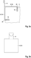
Fig. 1 eine Seitenansicht eines mit Hilfe einer nicht erfindungsgemäßen Tragkonstruktion abgehängten Schallabsorbers, -
Fig. 2 eine perspektivische Darstellung des Tragprofils und der Tragplatte der Tragkonstruktion derFig. 1 , -
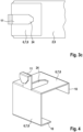
Fig. 3 a) eine Seitenansicht, b) eine weitere Seitenansicht und c) eine Draufsicht auf ein Winkelblech für eine erfindungsgemäße Tragkonstruktion, das gegenüber dem Winkelblech derFig. 1 modifiziert ist, -
Fig. 4 eine perspektivische Darstellung des Winkelblechs derFig. 3 , -
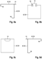
Fig. 5 a) eine Seitenansicht und b) eine Draufsicht auf ein drittes Winkelblech für eine erfindungsgemäße Tragkonstruktion, -
Fig. 6 a) eine Seitenansicht und b) eine Draufsicht auf ein viertes Winkelblech für eine erfindungsgemäße Tragkonstruktion, -
Fig. 7 eine perspektivische Darstellung des Winkelblechs derFig. 6 , -
Fig. 8 a) eine erste Seitenansicht, b) eine zweite Seitenansicht, c) eine dritte Seitenansicht und d) eine vierte Seitenansicht eines fünften Winkelblechs für eine erfindungsgemäße Tragkonstruktion, -
Fig. 9 a) eine erste perspektivische Darstellung und b) eine zweite perspektivische Darstellung eines sechsten Winkelblechs für eine erfindungsgemäße Tragkonstruktion, -
Fig. 10 eine perspektivische Darstellung des Winkelblechs derFig. 9 mit einem Tragprofil einer erfindungsgemäßen Tragkonstruktion, -
Fig. 11 eine perspektivische Darstellung einer erfindungsgemäßen Tragkonstruktion mit Schallabsorbern, -
Fig. 12 eine weitere perspektivische Darstellung der Tragkonstruktion derFig. 11 , -
Fig. 13 eine dritte perspektivische Darstellung der Tragkonstruktion derFig. 11 , -
Fig. 14 eine perspektivische Darstellung einer weiteren erfindungsgemäßen Tragkonstruktion, -
Fig. 15 eine perspektivische Darstellung eines weiteren Tragprofils für eine erfindungsgemäße Tragkonstruktion, -
Fig. 16 a) eine erste Seitenansicht des Tragprofils derFig. 15 beim Einhängen eines Schallabsorbers und b) eine zweite Seitenansicht des Tragprofils derFig. 15 mit eingehängtem Schallabsorber. -
Fig. 1 zeigt eine nicht erfindungsgemäße Tragkonstruktion 1 zur Abhängung eines Schallabsorbers 2 von einer Decke (nicht dargestellt). Wie derFig. 2 zu entnehmen ist, weist die Tragkonstruktion 1 ein Tragprofil 4 mit einem annähernd V-förmigen Querschnitt sowie eine Abhängeeinrichtung 5 mit einer Tragplatte 16 auf, die eine annähernd V-förmige Ausnehmung 17 zur Aufnahme des Tragprofils 4 besitzt. Zum Abhängen von der Decke weist die Tragplatte 16 mindestens eine Öffnung 22 für ein Drahtseil (nicht dargestellt) auf. Im Tragprofil 4 sind Ausnehmungen 13 ausgebildet, die der Aufnahme von Mitteln 6 zur Verbindung des Schallabsorbers 2 mit dem Tragprofil 4 dienen. - Die Mittel 6 zur Verbindung des Schallabsorbers 2 mit dem Tragprofil 4 umfassen ein Winkelblech 7, das in der
Fig. 1 dargestellt ist. Das dargestellte Winkelblech 7 weist zwei rechtwinklig zueinander angeordnete Schenkel 8 auf, die an zwei schmalen über Eck angeordneten Seitenflächen 9 des Schallabsorbers 2 anliegen und mit dem Schallabsorber 2 kraft- und stoffschlüssig verbunden sind. Der Kraftschluss wird über zwei seitlich abgekantete Stege 10 des Winkelblechs 7 bewirkt, welche klammerartig die obere Seitenfläche 9 des Schallabsorbers 2 umgreifen. Der Stoffschluss wird über eine Verklebung des Winkelblechs 7 mit dem Schallabsorber 2 bewirkt. Das Winkelblech 7 weist zudem eine Lasche 11 mit einer Ausnehmung auf, durch die ein weiteres Mittel 6 zur Verbindung des Schallabsorbers 2 mit dem Tragprofil 4 geführt ist. Das weitere Mittel 6 ist vorliegend ein Haken nach Art eines Karabinerhakens, der in die Ausnehmung 13 des Tragprofils 4 einhängbar ist. - Eine bevorzugte Ausführungsform einer erfindungsgemäßen Tragkonstruktion 1 mit abgewandeltem Winkelblech 7 ist den
Figuren 3 und4 zu entnehmen. Die Lasche 11 des Winkelblechs 7 ist mehrfach abgewinkelt und bildet somit einen Haken aus, der einen zusätzlichen Haken entbehrlich macht. Die Mittel 6 zur Verbindung des Schallabsorbers 2 mit dem Tragprofil 4 können somit auf das Winkelblech 7 reduziert werden. - Das Winkelblech 7 der
Figuren 3 und4 weist im Unterschied zum Winkelblech derFig. 1 Stege 10 zur formschlüssigen Verbindung mit dem Schallabsorber 2 auf. Die Stege 10 sind hierzu jeweils an den freien Enden der beiden Schenkel 8 angeordnet. In den Seitenflächen 9 des Schallabsorbers 2 können Nuten 23 zur Aufnahme der Stege 10 ausgebildet sein. Wie insbesondere derFig. 4 zu entnehmen ist, ist die Lasche 11 aus dem Material des Winkelblechs 7 hergestellt, und zwar in einem Stanz-Biegeverfahren. Der obere Schenkel 8 des Winkelblechs 7 weist dementsprechend eine Ausnehmung 24 auf. - Den
Figuren 5a) und 5b ) ist eine zweite bevorzugte Ausführungsform eines Winkelblechs 7 zu entnehmen. Die Lasche 11 ist nicht aus dem Material des oberen, sondem aus dem Material des unteren bzw. vertikal verlaufenden Schenkels 8 hergestellt und nur einmal abgewinkelt. Die Lasche 11 bildet somit ebenfalls einen Haken aus. Zudem gelangt der vertikal verlaufende Schenkel 8 des Winkelblechs 7 zur Anlage an einem vertikal verlaufenden Profilabschnitt 14 des Tragprofils 4, der somit eine Stützfläche 15 ausbildet (nicht dargestellt, siehe beispielhaftFig. 2 ). Die Abstützung des Winkelblechs 7 am Tragprofil 4 führt zu einer Aussteifung des gesamten Systems. Optional kann das Winkelblech 7 endseitige oder seitlich angeordnete Stege 10 zur kraft- und/oder formschlüssigen Verbindung mit dem Schallabsorber 2 aufweisen (sieheFig. 5a )). - Den
Figuren 6a) und 6b ) sowie derFig. 7 ist eine dritte bevorzugte Ausführungsform eines Winkelblechs 7 zu entnehmen. Die Lasche 11 ist hier nicht abgewinkelt ausgeführt, sondern weist einen Hinterschneidungsbereich 12 auf. Die Form der Lasche 11 ist somit hammerkopfartig. Bei der Herstellung des Winkelblechs in einem Stanz-/Biegeverfahren kann die Lasche gleich mit hergestellt werden. Mit Einsetzen der Lasche 11 in eine Ausnehmung 13 des Tragprofils 4 gelangt der vertikal verlaufende Schenkel 8 des Winkelblechs 7 wieder zur Anlage an dem Profilabschnitt 14, der eine Stützfläche 15 ausbildet. Demzufolge wird eine Aussteifung des Systems analog zu dem zuvor beschriebenen Ausführungsbeispiel erreicht. Optional können wiederum Stege 10 vorhanden sein, die endseitig oder seitlich an mindestens einem Schenkel 8 des Winkelblechs 7 zur kraft- und/oder formschlüssigen Verbindung mit dem Schallabsorber 2 vorgesehen sind (sieheFig. 7 ). - Den
Figuren 8a) bis 8d ) ist eine vierte bevorzugte Ausführungsform eines Winkelblechs 7 zu entnehmen. Die Lasche 11 ist auch hier hammerkopfartig mit einem Hinterschneidungsbereich 12 ausgebildet. Ferner sind an beiden Schenkeln 8 endseitige Stege 10 zur formschlüssigen Verbindung mit dem Schallabsorber 2 vorgesehen. - Den
Figuren 9a) und 9b ) ist eine fünfte bevorzugte Ausführungsform eines Winkelblechs 7 zu entnehmen. Im Unterschied zur Ausführungsform derFiguren 8a) bis 8d ) sind hier, und zwar lediglich am oberen Schenkel 8, seitliche Stege 10 vorgesehen, welche die obere Seitenfläche 9 des Schallabsorbers 2 umgreifen und auf diese Weise einen Kraftschluss mit dem Schallabsorber 2 herstellen (sieheFig. 9b )). Der untere bzw. vertikal verlaufende Schenkel 8 des Winkelblechs 7 ist mit dem Schallabsorber 2 zusätzlich verschraubt (sieheFig. 9a )). - Um das Winkelblech 7 der
Figuren 9a) und 9b ) mit einem Tragprofil 4 zu verbinden, muss lediglich die Lasche 11 in die Ausnehmung 13 des Tragprofils 4 eingesetzt werden. Bei einer hammerkopfförmigen Lasche 11 weist die Ausnehmung 13 eine hieran angepasste Form auf. Diese ist in derFig. 10 beispielhaft dargestellt. Die Ausnehmung 13 ist im Wesentlichen rechteckig mit einer gestuften Unterkante ausgeführt. Die gestufte Unterkante bildet einen verengten Bereich aus, der an den Hinterschneidungsbereich 12 der Lasche 11 angepasst ist, so dass beim Einsetzen der Lasche 11 der Hammerkopf die Wandung des Tragprofils 4 hintergreift. Auf diese Weise wird ein Formschluss zwischen dem Winkelblech 7 und dem Tragprofil 4 erreicht. - Den
Figuren 11 bis 13 ist eine erfindungsgemäße Tragkonstruktion 1 mit einem Tragprofil 4 und mehreren über Winkelbleche 7 mit dem Tragprofil 4 verbundene Schallabsorbern 2 zu entnehmen. Die Winkelbleche 7 sind analog den Winkelblechen 7 derFiguren 9a) und 9b ) ausgeführt. Das Tragprofil 4 ist analog dem Tragprofil 4 derFig. 10 gestaltet.Fig. 11 zeigt deutlich, wie sich das Winkelblech 7 an dem Profilabschnitt 14 bzw. der Stützfläche 15 des Tragprofils 4 abstützt. Weitere Schallabsorber 2 können in gleicher Weise auf der gegenüberliegenden Seite des Tragprofils 4 angeordnet werden, so dass das Tragprofil 4 mittig zwischen zwei Reihen von Schallabsorbern 2 verläuft. Die Schallabsorber 2 einer Reihe sind jeweils in einem Abstand zueinander angeordnet, wobei der Abstand durch den Abstand der im Tragprofil vorgesehenen Ausnehmungen 13 vorgegeben ist (sieheFiguren 12 und13 ). - Zur Abhängung des Tragprofils 4 weist die dargestellte Tragkonstruktion 1 Tragplatten 16 mit jeweils einer Ausnehmung 17 auf, durch die das Tragprofil 4 hindurchgeführt ist. Die Tragplatten 16 weisen am oberen Rand jeweils mindestens eine Öffnung 22 zur Verbindung mit einem Haken 20 auf, an dem ein Drahtseil 18 befestigt ist.
- Eine weitere bevorzugte Ausführungsform einer Tragkonstruktion 1 ist in der
Fig. 14 dargestellt. Hier weist das Tragprofil 4 einen im Wesentlichen C-förmigen Querschnitt mit beidseitig angeordneten vertikal verlaufenden Profilabschnitten 14 auf, die Stützflächen 15 ausbilden. Die Tragplatten 16 weisen jeweils eine Ausnehmung 17 auf, deren Innenkontur an die Außenkontur des Tragprofils 4 angepasst ist. Die Tragplatten 16 weisen zudem umlaufend die gleiche Breite auf. Im oberen Randbereich weisen die Tragplatten 16 jeweils eine Öffnung 22 zur Verbindung mit einem Drahtseil 18 bzw. einer endseitig ausgebildeten Schlaufe 19 des Drahtseils 18 auf. - Eine Weiterbildung einer erfindungsgemäßen Tragkonstruktion 1 ist in den
Figuren 15 sowie 16a) und 16b) dargestellt. Am Beispiel eines Tragprofils 4, das einen im Wesentlichen V-förmigen Querschnitt besitzt, wird gezeigt, dass die Ausnehmung 13 zur Aufnahme einer hammerkopfförmigen Lasche 11 eines Winkelblechs 7 nicht nur eine gestufte Unterkante, sondern auch eine gestufte Oberkante aufweisen kann. Die Stufung ist dergestalt, dass eine in die Ausnehmung 13 hineinragende Lasche 21 ausgebildet wird. Die Lasche 21 ist federnd ausgebildet, das heißt elastisch verformbar. Beim Einsetzen der Lasche 11 des Winkelblechs 7 wird die Lasche 21 des Tragprofils 4 zunächst weggedrückt (sieheFig. 16a )). Anschließend wird die Lasche 11 des Winkelblechs 7 abgelassen, so dass sie an der Unterkante der Ausnehmung 13 zur Anlage gelangt. Dies führt zu einem Zurückfedern der Lasche 21 des Tragprofils 4, so dass die Lasche 11 des Winkelblechs 7 von der Lasche 21 des Tragprofils 4 niedergehalten wird. Die Lasche 11 des Winkelblechs 7 ist somit vor Herausrutschen gesichert, da in dieser Position die hammerkopfförmige Lasche 11 von der Wandung des Tragprofils 4 hintergriffen wird. -
- 1
- Tragkonstruktion
- 2
- Schallabsorber
- 3
- Decke
- 4
- Tragprofil
- 5
- Abhängeeinrichtung
- 6
- Mittel zur Verbindung
- 7
- Winkelblech
- 8
- Schenkel
- 9
- Seitenfläche
- 10
- Steg
- 11
- Lasche
- 12
- Hinterschneidungsbereich
- 13
- Ausnehmung
- 14
- Profilabschnitt
- 15
- Stützfläche
- 16
- Tragplatte
- 17
- Ausnehmung
- 18
- Drahtseil
- 19
- Schlaufe
- 20
- Haken
- 21
- Lasche
- 22
- Öffnung
- 23
- Nut
- 24
- Ausnehmung
Claims (13)
- Tragkonstruktion (1) zur Abhängung mindestens eines Schallabsorbers (2) von einer Decke (3), umfassend ein längliches Tragprofil (4), eine mit dem Tragprofil (4) verbindbare Abhängeeinrichtung (5) sowie Mittel (6) zur Verbindung des Schallabsorbers (2) mit dem Tragprofil (4), wobei die Mittel (6) ein Winkelblech (7) umfassen, das mindestens zwei in einem Winkel, vorzugsweise in einem rechten Winkel, zueinander liegende Schenkel (8) aufweist, die in einem Eckbereich des Schallabsorbers (2) an zwei über Eck angeordnete Seitenflächen (9) des Schallabsorbers (2) anlegbar und mit dem Schallabsorber (2) kraft-, form- und/oder stoffschlüssig verbindbar sind,
dadurch gekennzeichnet, dass das Tragprofil (4) im Querschnitt im Wesentlichen V- oder U-förmig ausgebildet ist und einen Profilabschnitt (14) aufweist, der eine ebene Stützfläche (15) zur Abstützung eines Schenkels (8) des Winkelblechs (7) ausbildet. - Tragkonstruktion (1) nach Anspruch 1,
dadurch gekennzeichnet, dass mindestens ein Schenkel (8) des Winkelblechs (7), vorzugsweise an seinem freien Ende und/oder einer senkrecht hierzu verlaufenden Seitenkante, einen Steg (10) zur kraft-, form- und/oder stoffschlüssigen Verbindung mit dem Schallabsorber (2) aufweist. - Tragkonstruktion (1) nach Anspruch 1 oder 2,
dadurch gekennzeichnet, dass das Winkelblech (7) zur Verbindung mit dem Tragprofil (4) eine Lasche (11) aufweist, die zumindest abschnittsweise senkrecht zu einem der beiden Schenkel (8) verläuft und/oder in einer Ebene mit einem der beiden Schenkel (8) angeordnet ist. - Tragkonstruktion (1) nach Anspruch 3,
dadurch gekennzeichnet, dass die Lasche (11) endseitig ein- oder mehrfach abgewinkelt ist und/oder einen Hinterschneidungsbereich (12) aufweist. - Tragkonstruktion (1) nach einem der vorhergehenden Ansprüche,
dadurch gekennzeichnet, dass das Tragprofil (4) mindestens eine Ausnehmung (13), vorzugsweise mehrere in Reihe angeordnete Ausnehmungen (13), zur Verbindung mit dem Winkelblech (7), vorzugsweise zur Aufnahme der Lasche (11) des Winkelblechs (7), aufweist. - Tragkonstruktion (1) nach einem der vorhergehenden Ansprüche,
dadurch gekennzeichnet, dass das Tragprofil (4) und/oder das Winkelblech (7) aus Metall, insbesondere aus einem Metallblech, gefertigt ist bzw. sind, wobei vorzugsweise das Metallblech eine Dicke von 0,5 mm bis 3 mm aufweist. - Tragkonstruktion (1) nach einem der vorhergehenden Ansprüche,
dadurch gekennzeichnet, dass die Abhängeeinrichtung (5) eine Tragplatte (16) mit einer Ausnehmung (17) zur Aufnahme des Tragprofils (4) umfasst, wobei vorzugsweise die Ausnehmung (17) eine Innenkontur aufweist, die an eine Außenkontur des Tragprofils (4) angepasst ist. - Tragkonstruktion (1) nach einem der vorhergehenden Ansprüche,
dadurch gekennzeichnet, dass die Abhängeeinrichtung (5) ein Drahtseil (18) umfasst, das vorzugsweise an zumindest einem Ende eine Schlaufe (19) und/oder einen Haken (20) aufweist. - Tragkonstruktion (1) nach einem der vorhergehenden Ansprüche,
dadurch gekennzeichnet, dass die Abhängeeinrichtung (5) eine Gewindestange mit Muttern, Unterlegscheiben und Hakenelementen umfasst oder eine Nonius-Abhängeeinrichtung aus dem Trockenbau ist. - System zur Verbesserung der Akustik in einem Raum, umfassend eine Tragkonstruktion (1) nach einem der vorhergehenden Ansprüche sowie mindestens einen Schallabsorber (2), wobei das Winkelblech (7) der Tragkonstruktion in einem Eckbereich des Schallabsorbers (2) an zwei über Eck angeordnete Seitenflächen (9) des Schallabsorbers (2) angelegt und mit dem Schallabsorber (2) kraft-, form- und/oder stoffschlüssig verbunden ist.
- System nach Anspruch 10,
dadurch gekennzeichnet, dass der Schallabsorber (2) im Wesentlichen plattenförmig ausgebildet ist. - System nach Anspruch 10 oder 11,
dadurch gekennzeichnet, dass der Schallabsorber (2) aus einem schallabsorbierenden Material gefertigt ist und/oder eine raumakustisch wirksame Oberflächenstruktur ausweist. - System nach einem der Ansprüche 10 bis 12,
dadurch gekennzeichnet, dass der Schallabsorber (2) eine Dicke (d) von 10 mm bis 200 mm, vorzugsweise von 10 mm bis 150 mm, weiterhin vorzugsweise von 20 mm bis 100 mm aufweist.
Priority Applications (1)
| Application Number | Priority Date | Filing Date | Title |
|---|---|---|---|
| EP20173882.0A EP3910125B1 (de) | 2020-05-11 | 2020-05-11 | Tragkonstruktion zur abhängung mindestens eines schallabsorbers von einer decke, system zur verbesserung der akustik in einem raum |
Applications Claiming Priority (1)
| Application Number | Priority Date | Filing Date | Title |
|---|---|---|---|
| EP20173882.0A EP3910125B1 (de) | 2020-05-11 | 2020-05-11 | Tragkonstruktion zur abhängung mindestens eines schallabsorbers von einer decke, system zur verbesserung der akustik in einem raum |
Publications (2)
| Publication Number | Publication Date |
|---|---|
| EP3910125A1 EP3910125A1 (de) | 2021-11-17 |
| EP3910125B1 true EP3910125B1 (de) | 2025-01-22 |
Family
ID=70681651
Family Applications (1)
| Application Number | Title | Priority Date | Filing Date |
|---|---|---|---|
| EP20173882.0A Active EP3910125B1 (de) | 2020-05-11 | 2020-05-11 | Tragkonstruktion zur abhängung mindestens eines schallabsorbers von einer decke, system zur verbesserung der akustik in einem raum |
Country Status (1)
| Country | Link |
|---|---|
| EP (1) | EP3910125B1 (de) |
Families Citing this family (1)
| Publication number | Priority date | Publication date | Assignee | Title |
|---|---|---|---|---|
| CN116591371B (zh) * | 2023-05-18 | 2026-01-30 | 沈阳建筑大学 | 一种模块化可变式吸音吊顶及其施工方法 |
Citations (2)
| Publication number | Priority date | Publication date | Assignee | Title |
|---|---|---|---|---|
| DE4204638A1 (de) * | 1992-02-15 | 1993-08-19 | Rockwool Systeme Gmbh | Vorrichtung zur schalldaemmung in raeumen |
| DE102004037909A1 (de) * | 2004-08-05 | 2006-03-16 | Bruno Henle | Anordnung zur hängenden Halterung von Schallabsorbern |
Family Cites Families (3)
| Publication number | Priority date | Publication date | Assignee | Title |
|---|---|---|---|---|
| FR2386656A1 (fr) * | 1977-04-05 | 1978-11-03 | Miguet Ets Marcel | Ensemble vertical pour plafond suspendu |
| DE9006457U1 (de) | 1990-06-08 | 1990-08-16 | Ecophon Ab, Hyllinge | Vorrichtung zur Schalldämmung in Großräumen |
| US8695296B2 (en) * | 2011-05-17 | 2014-04-15 | Awi Licensing Company | Mounting hardware and mounting system for vertical panels |
-
2020
- 2020-05-11 EP EP20173882.0A patent/EP3910125B1/de active Active
Patent Citations (2)
| Publication number | Priority date | Publication date | Assignee | Title |
|---|---|---|---|---|
| DE4204638A1 (de) * | 1992-02-15 | 1993-08-19 | Rockwool Systeme Gmbh | Vorrichtung zur schalldaemmung in raeumen |
| DE102004037909A1 (de) * | 2004-08-05 | 2006-03-16 | Bruno Henle | Anordnung zur hängenden Halterung von Schallabsorbern |
Also Published As
| Publication number | Publication date |
|---|---|
| EP3910125A1 (de) | 2021-11-17 |
Similar Documents
| Publication | Publication Date | Title |
|---|---|---|
| EP2354368B1 (de) | Befestigungsbügel für Wandisolierungen | |
| EP0206146A2 (de) | Ünterkonstruktion für Bauwerksverkleidungen | |
| EP3574164B1 (de) | Konsole zur befestigung von fassadenelementen | |
| EP3910125B1 (de) | Tragkonstruktion zur abhängung mindestens eines schallabsorbers von einer decke, system zur verbesserung der akustik in einem raum | |
| DE202018003027U1 (de) | Verbindungsstück zur winkeligen Verbindung zweier Bauteile | |
| EP0430224B1 (de) | Befestigungsvorrichtung | |
| DE4437319A1 (de) | Einbruchhemmender Schirm für ein Wandelement, einbruchhemmendes Wandelement und einbruchhemmende Wand | |
| EP2862984B1 (de) | Fachwerk zur Verglasung eines Gebäudes | |
| WO2025056429A1 (de) | Haltevorrichtung für eine elektronische einrichtung | |
| DE102010018593A1 (de) | Verbindungsbeschlag | |
| EP0006245B1 (de) | Fassadenunterkonstruktion | |
| DE202009012001U1 (de) | Tragkonstruktion für Bauelemente, insbesondere für Photovoltaikpaneele | |
| EP0026495A2 (de) | Wandhalteprofilsatz zur Befestigung einer Unterkonstruktion für Fassadenplatten an Gebäudewänden | |
| DE4204638A1 (de) | Vorrichtung zur schalldaemmung in raeumen | |
| DE202024105271U1 (de) | Ausgleichsbauteil für mit Abstand montiertes Gebäudeteil | |
| DE202020100059U1 (de) | Schalungselement | |
| CH672523A5 (de) | ||
| EP1936054B9 (de) | Zuglasche zur Befestigung von Porenbetonwandplatten, sowie Porenbetonwandplattensystem mit Zuglaschen | |
| EP0638694B1 (de) | Abhängeranker für Doppel T-Träger | |
| WO2005059268A1 (de) | Tragbügel zur befestigung von fassadenelementen od.dgl. an aussenwänden von gebäuden | |
| EP1878842B1 (de) | Aus Stäben gebildete Verkleidung von Decken, Wänden oder dergleichen Bauwerkteilen | |
| DE202009012416U1 (de) | Befestigungsvorrichtung zur Anordnung einer Torzarge an einer Wand | |
| EP3263788A1 (de) | Verbindung zweier holzbalken | |
| DE202022103708U1 (de) | Einhängeelement für Ankerplatte eines Seitenunfallschutzes, Ankerplatte für Seitenunfallschutz sowie System aus Ankerplatte und Einhängeelement | |
| AT406174B (de) | Befestigungsteil für profile |
Legal Events
| Date | Code | Title | Description |
|---|---|---|---|
| PUAI | Public reference made under article 153(3) epc to a published international application that has entered the european phase |
Free format text: ORIGINAL CODE: 0009012 |
|
| STAA | Information on the status of an ep patent application or granted ep patent |
Free format text: STATUS: REQUEST FOR EXAMINATION WAS MADE |
|
| 17P | Request for examination filed |
Effective date: 20210122 |
|
| AK | Designated contracting states |
Kind code of ref document: A1 Designated state(s): AL AT BE BG CH CY CZ DE DK EE ES FI FR GB GR HR HU IE IS IT LI LT LU LV MC MK MT NL NO PL PT RO RS SE SI SK SM TR |
|
| B565 | Issuance of search results under rule 164(2) epc |
Effective date: 20201015 |
|
| STAA | Information on the status of an ep patent application or granted ep patent |
Free format text: STATUS: EXAMINATION IS IN PROGRESS |
|
| 17Q | First examination report despatched |
Effective date: 20231120 |
|
| GRAP | Despatch of communication of intention to grant a patent |
Free format text: ORIGINAL CODE: EPIDOSNIGR1 |
|
| STAA | Information on the status of an ep patent application or granted ep patent |
Free format text: STATUS: GRANT OF PATENT IS INTENDED |
|
| INTG | Intention to grant announced |
Effective date: 20240905 |
|
| GRAS | Grant fee paid |
Free format text: ORIGINAL CODE: EPIDOSNIGR3 |
|
| GRAA | (expected) grant |
Free format text: ORIGINAL CODE: 0009210 |
|
| STAA | Information on the status of an ep patent application or granted ep patent |
Free format text: STATUS: THE PATENT HAS BEEN GRANTED |
|
| AK | Designated contracting states |
Kind code of ref document: B1 Designated state(s): AL AT BE BG CH CY CZ DE DK EE ES FI FR GB GR HR HU IE IS IT LI LT LU LV MC MK MT NL NO PL PT RO RS SE SI SK SM TR |
|
| REG | Reference to a national code |
Ref country code: GB Ref legal event code: FG4D Free format text: NOT ENGLISH |
|
| REG | Reference to a national code |
Ref country code: CH Ref legal event code: EP |
|
| REG | Reference to a national code |
Ref country code: IE Ref legal event code: FG4D Free format text: LANGUAGE OF EP DOCUMENT: GERMAN |
|
| REG | Reference to a national code |
Ref country code: DE Ref legal event code: R096 Ref document number: 502020010236 Country of ref document: DE |
|
| REG | Reference to a national code |
Ref country code: NL Ref legal event code: FP |
|
| PGFP | Annual fee paid to national office [announced via postgrant information from national office to epo] |
Ref country code: NL Payment date: 20250521 Year of fee payment: 6 |
|
| PG25 | Lapsed in a contracting state [announced via postgrant information from national office to epo] |
Ref country code: RS Free format text: LAPSE BECAUSE OF FAILURE TO SUBMIT A TRANSLATION OF THE DESCRIPTION OR TO PAY THE FEE WITHIN THE PRESCRIBED TIME-LIMIT Effective date: 20250422 |
|
| PG25 | Lapsed in a contracting state [announced via postgrant information from national office to epo] |
Ref country code: FI Free format text: LAPSE BECAUSE OF FAILURE TO SUBMIT A TRANSLATION OF THE DESCRIPTION OR TO PAY THE FEE WITHIN THE PRESCRIBED TIME-LIMIT Effective date: 20250122 |
|
| PG25 | Lapsed in a contracting state [announced via postgrant information from national office to epo] |
Ref country code: PL Free format text: LAPSE BECAUSE OF FAILURE TO SUBMIT A TRANSLATION OF THE DESCRIPTION OR TO PAY THE FEE WITHIN THE PRESCRIBED TIME-LIMIT Effective date: 20250122 |
|
| PGFP | Annual fee paid to national office [announced via postgrant information from national office to epo] |
Ref country code: DE Payment date: 20250521 Year of fee payment: 6 |
|
| PG25 | Lapsed in a contracting state [announced via postgrant information from national office to epo] |
Ref country code: ES Free format text: LAPSE BECAUSE OF FAILURE TO SUBMIT A TRANSLATION OF THE DESCRIPTION OR TO PAY THE FEE WITHIN THE PRESCRIBED TIME-LIMIT Effective date: 20250122 |
|
| REG | Reference to a national code |
Ref country code: LT Ref legal event code: MG9D |
|
| PG25 | Lapsed in a contracting state [announced via postgrant information from national office to epo] |
Ref country code: NO Free format text: LAPSE BECAUSE OF FAILURE TO SUBMIT A TRANSLATION OF THE DESCRIPTION OR TO PAY THE FEE WITHIN THE PRESCRIBED TIME-LIMIT Effective date: 20250422 Ref country code: IS Free format text: LAPSE BECAUSE OF FAILURE TO SUBMIT A TRANSLATION OF THE DESCRIPTION OR TO PAY THE FEE WITHIN THE PRESCRIBED TIME-LIMIT Effective date: 20250522 |
|
| PG25 | Lapsed in a contracting state [announced via postgrant information from national office to epo] |
Ref country code: HR Free format text: LAPSE BECAUSE OF FAILURE TO SUBMIT A TRANSLATION OF THE DESCRIPTION OR TO PAY THE FEE WITHIN THE PRESCRIBED TIME-LIMIT Effective date: 20250122 |
|
| PG25 | Lapsed in a contracting state [announced via postgrant information from national office to epo] |
Ref country code: LV Free format text: LAPSE BECAUSE OF FAILURE TO SUBMIT A TRANSLATION OF THE DESCRIPTION OR TO PAY THE FEE WITHIN THE PRESCRIBED TIME-LIMIT Effective date: 20250122 Ref country code: PT Free format text: LAPSE BECAUSE OF FAILURE TO SUBMIT A TRANSLATION OF THE DESCRIPTION OR TO PAY THE FEE WITHIN THE PRESCRIBED TIME-LIMIT Effective date: 20250522 |
|
| PGFP | Annual fee paid to national office [announced via postgrant information from national office to epo] |
Ref country code: FR Payment date: 20250528 Year of fee payment: 6 |
|
| PG25 | Lapsed in a contracting state [announced via postgrant information from national office to epo] |
Ref country code: BG Free format text: LAPSE BECAUSE OF FAILURE TO SUBMIT A TRANSLATION OF THE DESCRIPTION OR TO PAY THE FEE WITHIN THE PRESCRIBED TIME-LIMIT Effective date: 20250122 Ref country code: GR Free format text: LAPSE BECAUSE OF FAILURE TO SUBMIT A TRANSLATION OF THE DESCRIPTION OR TO PAY THE FEE WITHIN THE PRESCRIBED TIME-LIMIT Effective date: 20250423 |
|
| PGFP | Annual fee paid to national office [announced via postgrant information from national office to epo] |
Ref country code: CH Payment date: 20250601 Year of fee payment: 6 |
|
| PGFP | Annual fee paid to national office [announced via postgrant information from national office to epo] |
Ref country code: AT Payment date: 20250522 Year of fee payment: 6 |
|
| PG25 | Lapsed in a contracting state [announced via postgrant information from national office to epo] |
Ref country code: SE Free format text: LAPSE BECAUSE OF FAILURE TO SUBMIT A TRANSLATION OF THE DESCRIPTION OR TO PAY THE FEE WITHIN THE PRESCRIBED TIME-LIMIT Effective date: 20250122 |
|
| PG25 | Lapsed in a contracting state [announced via postgrant information from national office to epo] |
Ref country code: SM Free format text: LAPSE BECAUSE OF FAILURE TO SUBMIT A TRANSLATION OF THE DESCRIPTION OR TO PAY THE FEE WITHIN THE PRESCRIBED TIME-LIMIT Effective date: 20250122 |
|
| PG25 | Lapsed in a contracting state [announced via postgrant information from national office to epo] |
Ref country code: DK Free format text: LAPSE BECAUSE OF FAILURE TO SUBMIT A TRANSLATION OF THE DESCRIPTION OR TO PAY THE FEE WITHIN THE PRESCRIBED TIME-LIMIT Effective date: 20250122 |
|
| PG25 | Lapsed in a contracting state [announced via postgrant information from national office to epo] |
Ref country code: IT Free format text: LAPSE BECAUSE OF FAILURE TO SUBMIT A TRANSLATION OF THE DESCRIPTION OR TO PAY THE FEE WITHIN THE PRESCRIBED TIME-LIMIT Effective date: 20250122 |
|
| PG25 | Lapsed in a contracting state [announced via postgrant information from national office to epo] |
Ref country code: EE Free format text: LAPSE BECAUSE OF FAILURE TO SUBMIT A TRANSLATION OF THE DESCRIPTION OR TO PAY THE FEE WITHIN THE PRESCRIBED TIME-LIMIT Effective date: 20250122 Ref country code: CZ Free format text: LAPSE BECAUSE OF FAILURE TO SUBMIT A TRANSLATION OF THE DESCRIPTION OR TO PAY THE FEE WITHIN THE PRESCRIBED TIME-LIMIT Effective date: 20250122 |
|
| REG | Reference to a national code |
Ref country code: DE Ref legal event code: R097 Ref document number: 502020010236 Country of ref document: DE |
|
| PG25 | Lapsed in a contracting state [announced via postgrant information from national office to epo] |
Ref country code: RO Free format text: LAPSE BECAUSE OF FAILURE TO SUBMIT A TRANSLATION OF THE DESCRIPTION OR TO PAY THE FEE WITHIN THE PRESCRIBED TIME-LIMIT Effective date: 20250122 |
|
| PG25 | Lapsed in a contracting state [announced via postgrant information from national office to epo] |
Ref country code: SK Free format text: LAPSE BECAUSE OF FAILURE TO SUBMIT A TRANSLATION OF THE DESCRIPTION OR TO PAY THE FEE WITHIN THE PRESCRIBED TIME-LIMIT Effective date: 20250122 |
|
| P01 | Opt-out of the competence of the unified patent court (upc) registered |
Free format text: CASE NUMBER: UPC_APP_0010493_3910125/2025 Effective date: 20251021 |
|
| PLBE | No opposition filed within time limit |
Free format text: ORIGINAL CODE: 0009261 |
|
| STAA | Information on the status of an ep patent application or granted ep patent |
Free format text: STATUS: NO OPPOSITION FILED WITHIN TIME LIMIT |
|
| 26N | No opposition filed |
Effective date: 20251023 |
|
| PG25 | Lapsed in a contracting state [announced via postgrant information from national office to epo] |
Ref country code: LU Free format text: LAPSE BECAUSE OF NON-PAYMENT OF DUE FEES Effective date: 20250511 |
|
| GBPC | Gb: european patent ceased through non-payment of renewal fee |
Effective date: 20250511 |
|
| REG | Reference to a national code |
Ref country code: BE Ref legal event code: MM Effective date: 20250531 |
|
| PG25 | Lapsed in a contracting state [announced via postgrant information from national office to epo] |
Ref country code: MC Free format text: LAPSE BECAUSE OF FAILURE TO SUBMIT A TRANSLATION OF THE DESCRIPTION OR TO PAY THE FEE WITHIN THE PRESCRIBED TIME-LIMIT Effective date: 20250122 |
|
| PG25 | Lapsed in a contracting state [announced via postgrant information from national office to epo] |
Ref country code: GB Free format text: LAPSE BECAUSE OF NON-PAYMENT OF DUE FEES Effective date: 20250511 |
|
| PG25 | Lapsed in a contracting state [announced via postgrant information from national office to epo] |
Ref country code: IE Free format text: LAPSE BECAUSE OF NON-PAYMENT OF DUE FEES Effective date: 20250511 |
|
| PG25 | Lapsed in a contracting state [announced via postgrant information from national office to epo] |
Ref country code: BE Free format text: LAPSE BECAUSE OF NON-PAYMENT OF DUE FEES Effective date: 20250531 |