EP3910192A1 - Turbine à eau et/ou pompe à eau - Google Patents
Turbine à eau et/ou pompe à eau Download PDFInfo
- Publication number
- EP3910192A1 EP3910192A1 EP21173428.0A EP21173428A EP3910192A1 EP 3910192 A1 EP3910192 A1 EP 3910192A1 EP 21173428 A EP21173428 A EP 21173428A EP 3910192 A1 EP3910192 A1 EP 3910192A1
- Authority
- EP
- European Patent Office
- Prior art keywords
- rotor
- water
- bearing
- turbine
- water pump
- Prior art date
- Legal status (The legal status is an assumption and is not a legal conclusion. Google has not performed a legal analysis and makes no representation as to the accuracy of the status listed.)
- Granted
Links
Images


Classifications
-
- F—MECHANICAL ENGINEERING; LIGHTING; HEATING; WEAPONS; BLASTING
- F03—MACHINES OR ENGINES FOR LIQUIDS; WIND, SPRING, OR WEIGHT MOTORS; PRODUCING MECHANICAL POWER OR A REACTIVE PROPULSIVE THRUST, NOT OTHERWISE PROVIDED FOR
- F03B—MACHINES OR ENGINES FOR LIQUIDS
- F03B11/00—Parts or details not provided for in, or of interest apart from, the preceding groups, e.g. wear-protection couplings, between turbine and generator
- F03B11/06—Bearing arrangements
-
- F—MECHANICAL ENGINEERING; LIGHTING; HEATING; WEAPONS; BLASTING
- F03—MACHINES OR ENGINES FOR LIQUIDS; WIND, SPRING, OR WEIGHT MOTORS; PRODUCING MECHANICAL POWER OR A REACTIVE PROPULSIVE THRUST, NOT OTHERWISE PROVIDED FOR
- F03B—MACHINES OR ENGINES FOR LIQUIDS
- F03B11/00—Parts or details not provided for in, or of interest apart from, the preceding groups, e.g. wear-protection couplings, between turbine and generator
- F03B11/06—Bearing arrangements
- F03B11/063—Arrangements for balancing axial thrust
- F03B11/066—Arrangements for balancing axial thrust in vertical axis machines
-
- F—MECHANICAL ENGINEERING; LIGHTING; HEATING; WEAPONS; BLASTING
- F16—ENGINEERING ELEMENTS AND UNITS; GENERAL MEASURES FOR PRODUCING AND MAINTAINING EFFECTIVE FUNCTIONING OF MACHINES OR INSTALLATIONS; THERMAL INSULATION IN GENERAL
- F16C—SHAFTS; FLEXIBLE SHAFTS; ELEMENTS OR CRANKSHAFT MECHANISMS; ROTARY BODIES OTHER THAN GEARING ELEMENTS; BEARINGS
- F16C35/00—Rigid support of bearing units; Housings, e.g. caps, covers
- F16C35/04—Rigid support of bearing units; Housings, e.g. caps, covers in the case of ball or roller bearings
- F16C35/06—Mounting or dismounting of ball or roller bearings; Fixing them onto shaft or in housing
- F16C35/063—Fixing them on the shaft
-
- F—MECHANICAL ENGINEERING; LIGHTING; HEATING; WEAPONS; BLASTING
- F16—ENGINEERING ELEMENTS AND UNITS; GENERAL MEASURES FOR PRODUCING AND MAINTAINING EFFECTIVE FUNCTIONING OF MACHINES OR INSTALLATIONS; THERMAL INSULATION IN GENERAL
- F16C—SHAFTS; FLEXIBLE SHAFTS; ELEMENTS OR CRANKSHAFT MECHANISMS; ROTARY BODIES OTHER THAN GEARING ELEMENTS; BEARINGS
- F16C35/00—Rigid support of bearing units; Housings, e.g. caps, covers
- F16C35/04—Rigid support of bearing units; Housings, e.g. caps, covers in the case of ball or roller bearings
- F16C35/06—Mounting or dismounting of ball or roller bearings; Fixing them onto shaft or in housing
- F16C35/067—Fixing them in a housing
-
- F—MECHANICAL ENGINEERING; LIGHTING; HEATING; WEAPONS; BLASTING
- F16—ENGINEERING ELEMENTS AND UNITS; GENERAL MEASURES FOR PRODUCING AND MAINTAINING EFFECTIVE FUNCTIONING OF MACHINES OR INSTALLATIONS; THERMAL INSULATION IN GENERAL
- F16C—SHAFTS; FLEXIBLE SHAFTS; ELEMENTS OR CRANKSHAFT MECHANISMS; ROTARY BODIES OTHER THAN GEARING ELEMENTS; BEARINGS
- F16C35/00—Rigid support of bearing units; Housings, e.g. caps, covers
- F16C35/04—Rigid support of bearing units; Housings, e.g. caps, covers in the case of ball or roller bearings
- F16C35/06—Mounting or dismounting of ball or roller bearings; Fixing them onto shaft or in housing
- F16C35/07—Fixing them on the shaft or housing with interposition of an element
- F16C35/073—Fixing them on the shaft or housing with interposition of an element between shaft and inner race ring
-
- F—MECHANICAL ENGINEERING; LIGHTING; HEATING; WEAPONS; BLASTING
- F16—ENGINEERING ELEMENTS AND UNITS; GENERAL MEASURES FOR PRODUCING AND MAINTAINING EFFECTIVE FUNCTIONING OF MACHINES OR INSTALLATIONS; THERMAL INSULATION IN GENERAL
- F16C—SHAFTS; FLEXIBLE SHAFTS; ELEMENTS OR CRANKSHAFT MECHANISMS; ROTARY BODIES OTHER THAN GEARING ELEMENTS; BEARINGS
- F16C35/00—Rigid support of bearing units; Housings, e.g. caps, covers
- F16C35/04—Rigid support of bearing units; Housings, e.g. caps, covers in the case of ball or roller bearings
- F16C35/06—Mounting or dismounting of ball or roller bearings; Fixing them onto shaft or in housing
- F16C35/07—Fixing them on the shaft or housing with interposition of an element
- F16C35/077—Fixing them on the shaft or housing with interposition of an element between housing and outer race ring
-
- F—MECHANICAL ENGINEERING; LIGHTING; HEATING; WEAPONS; BLASTING
- F05—INDEXING SCHEMES RELATING TO ENGINES OR PUMPS IN VARIOUS SUBCLASSES OF CLASSES F01-F04
- F05B—INDEXING SCHEME RELATING TO WIND, SPRING, WEIGHT, INERTIA OR LIKE MOTORS, TO MACHINES OR ENGINES FOR LIQUIDS COVERED BY SUBCLASSES F03B, F03D AND F03G
- F05B2240/00—Components
- F05B2240/50—Bearings
- F05B2240/52—Axial thrust bearings
-
- F—MECHANICAL ENGINEERING; LIGHTING; HEATING; WEAPONS; BLASTING
- F05—INDEXING SCHEMES RELATING TO ENGINES OR PUMPS IN VARIOUS SUBCLASSES OF CLASSES F01-F04
- F05B—INDEXING SCHEME RELATING TO WIND, SPRING, WEIGHT, INERTIA OR LIKE MOTORS, TO MACHINES OR ENGINES FOR LIQUIDS COVERED BY SUBCLASSES F03B, F03D AND F03G
- F05B2240/00—Components
- F05B2240/50—Bearings
- F05B2240/54—Radial bearings
-
- F—MECHANICAL ENGINEERING; LIGHTING; HEATING; WEAPONS; BLASTING
- F16—ENGINEERING ELEMENTS AND UNITS; GENERAL MEASURES FOR PRODUCING AND MAINTAINING EFFECTIVE FUNCTIONING OF MACHINES OR INSTALLATIONS; THERMAL INSULATION IN GENERAL
- F16C—SHAFTS; FLEXIBLE SHAFTS; ELEMENTS OR CRANKSHAFT MECHANISMS; ROTARY BODIES OTHER THAN GEARING ELEMENTS; BEARINGS
- F16C17/00—Sliding-contact bearings for exclusively rotary movement
- F16C17/10—Sliding-contact bearings for exclusively rotary movement for both radial and axial load
- F16C17/102—Sliding-contact bearings for exclusively rotary movement for both radial and axial load with grooves in the bearing surface to generate hydrodynamic pressure
- F16C17/105—Sliding-contact bearings for exclusively rotary movement for both radial and axial load with grooves in the bearing surface to generate hydrodynamic pressure with at least one bearing surface providing angular contact, e.g. conical or spherical bearing surfaces
-
- F—MECHANICAL ENGINEERING; LIGHTING; HEATING; WEAPONS; BLASTING
- F16—ENGINEERING ELEMENTS AND UNITS; GENERAL MEASURES FOR PRODUCING AND MAINTAINING EFFECTIVE FUNCTIONING OF MACHINES OR INSTALLATIONS; THERMAL INSULATION IN GENERAL
- F16C—SHAFTS; FLEXIBLE SHAFTS; ELEMENTS OR CRANKSHAFT MECHANISMS; ROTARY BODIES OTHER THAN GEARING ELEMENTS; BEARINGS
- F16C17/00—Sliding-contact bearings for exclusively rotary movement
- F16C17/10—Sliding-contact bearings for exclusively rotary movement for both radial and axial load
- F16C17/102—Sliding-contact bearings for exclusively rotary movement for both radial and axial load with grooves in the bearing surface to generate hydrodynamic pressure
- F16C17/107—Sliding-contact bearings for exclusively rotary movement for both radial and axial load with grooves in the bearing surface to generate hydrodynamic pressure with at least one surface for radial load and at least one surface for axial load
-
- F—MECHANICAL ENGINEERING; LIGHTING; HEATING; WEAPONS; BLASTING
- F16—ENGINEERING ELEMENTS AND UNITS; GENERAL MEASURES FOR PRODUCING AND MAINTAINING EFFECTIVE FUNCTIONING OF MACHINES OR INSTALLATIONS; THERMAL INSULATION IN GENERAL
- F16C—SHAFTS; FLEXIBLE SHAFTS; ELEMENTS OR CRANKSHAFT MECHANISMS; ROTARY BODIES OTHER THAN GEARING ELEMENTS; BEARINGS
- F16C19/00—Bearings with rolling contact, for exclusively rotary movement
- F16C19/02—Bearings with rolling contact, for exclusively rotary movement with bearing balls essentially of the same size in one or more circular rows
- F16C19/14—Bearings with rolling contact, for exclusively rotary movement with bearing balls essentially of the same size in one or more circular rows for both radial and axial load
- F16C19/18—Bearings with rolling contact, for exclusively rotary movement with bearing balls essentially of the same size in one or more circular rows for both radial and axial load with two or more rows of balls
- F16C19/181—Bearings with rolling contact, for exclusively rotary movement with bearing balls essentially of the same size in one or more circular rows for both radial and axial load with two or more rows of balls with angular contact
- F16C19/183—Bearings with rolling contact, for exclusively rotary movement with bearing balls essentially of the same size in one or more circular rows for both radial and axial load with two or more rows of balls with angular contact with two rows at opposite angles
- F16C19/184—Bearings with rolling contact, for exclusively rotary movement with bearing balls essentially of the same size in one or more circular rows for both radial and axial load with two or more rows of balls with angular contact with two rows at opposite angles in O-arrangement
-
- F—MECHANICAL ENGINEERING; LIGHTING; HEATING; WEAPONS; BLASTING
- F16—ENGINEERING ELEMENTS AND UNITS; GENERAL MEASURES FOR PRODUCING AND MAINTAINING EFFECTIVE FUNCTIONING OF MACHINES OR INSTALLATIONS; THERMAL INSULATION IN GENERAL
- F16C—SHAFTS; FLEXIBLE SHAFTS; ELEMENTS OR CRANKSHAFT MECHANISMS; ROTARY BODIES OTHER THAN GEARING ELEMENTS; BEARINGS
- F16C2300/00—Application independent of particular apparatuses
- F16C2300/10—Application independent of particular apparatuses related to size
- F16C2300/14—Large applications, e.g. bearings having an inner diameter exceeding 500 mm
-
- F—MECHANICAL ENGINEERING; LIGHTING; HEATING; WEAPONS; BLASTING
- F16—ENGINEERING ELEMENTS AND UNITS; GENERAL MEASURES FOR PRODUCING AND MAINTAINING EFFECTIVE FUNCTIONING OF MACHINES OR INSTALLATIONS; THERMAL INSULATION IN GENERAL
- F16C—SHAFTS; FLEXIBLE SHAFTS; ELEMENTS OR CRANKSHAFT MECHANISMS; ROTARY BODIES OTHER THAN GEARING ELEMENTS; BEARINGS
- F16C2300/00—Application independent of particular apparatuses
- F16C2300/30—Application independent of particular apparatuses related to direction with respect to gravity
- F16C2300/34—Vertical, e.g. bearings for supporting a vertical shaft
-
- F—MECHANICAL ENGINEERING; LIGHTING; HEATING; WEAPONS; BLASTING
- F16—ENGINEERING ELEMENTS AND UNITS; GENERAL MEASURES FOR PRODUCING AND MAINTAINING EFFECTIVE FUNCTIONING OF MACHINES OR INSTALLATIONS; THERMAL INSULATION IN GENERAL
- F16C—SHAFTS; FLEXIBLE SHAFTS; ELEMENTS OR CRANKSHAFT MECHANISMS; ROTARY BODIES OTHER THAN GEARING ELEMENTS; BEARINGS
- F16C2300/00—Application independent of particular apparatuses
- F16C2300/40—Application independent of particular apparatuses related to environment, i.e. operating conditions
- F16C2300/42—Application independent of particular apparatuses related to environment, i.e. operating conditions corrosive, i.e. with aggressive media or harsh conditions
-
- F—MECHANICAL ENGINEERING; LIGHTING; HEATING; WEAPONS; BLASTING
- F16—ENGINEERING ELEMENTS AND UNITS; GENERAL MEASURES FOR PRODUCING AND MAINTAINING EFFECTIVE FUNCTIONING OF MACHINES OR INSTALLATIONS; THERMAL INSULATION IN GENERAL
- F16C—SHAFTS; FLEXIBLE SHAFTS; ELEMENTS OR CRANKSHAFT MECHANISMS; ROTARY BODIES OTHER THAN GEARING ELEMENTS; BEARINGS
- F16C2360/00—Engines or pumps
-
- F—MECHANICAL ENGINEERING; LIGHTING; HEATING; WEAPONS; BLASTING
- F16—ENGINEERING ELEMENTS AND UNITS; GENERAL MEASURES FOR PRODUCING AND MAINTAINING EFFECTIVE FUNCTIONING OF MACHINES OR INSTALLATIONS; THERMAL INSULATION IN GENERAL
- F16C—SHAFTS; FLEXIBLE SHAFTS; ELEMENTS OR CRANKSHAFT MECHANISMS; ROTARY BODIES OTHER THAN GEARING ELEMENTS; BEARINGS
- F16C33/00—Parts of bearings; Special methods for making bearings or parts thereof
- F16C33/30—Parts of ball or roller bearings
- F16C33/66—Special parts or details in view of lubrication
- F16C33/6637—Special parts or details in view of lubrication with liquid lubricant
- F16C33/6659—Details of supply of the liquid to the bearing, e.g. passages or nozzles
- F16C33/6666—Details of supply of the liquid to the bearing, e.g. passages or nozzles from an oil bath in the bearing housing, e.g. by an oil ring or centrifugal disc
-
- Y—GENERAL TAGGING OF NEW TECHNOLOGICAL DEVELOPMENTS; GENERAL TAGGING OF CROSS-SECTIONAL TECHNOLOGIES SPANNING OVER SEVERAL SECTIONS OF THE IPC; TECHNICAL SUBJECTS COVERED BY FORMER USPC CROSS-REFERENCE ART COLLECTIONS [XRACs] AND DIGESTS
- Y02—TECHNOLOGIES OR APPLICATIONS FOR MITIGATION OR ADAPTATION AGAINST CLIMATE CHANGE
- Y02E—REDUCTION OF GREENHOUSE GAS [GHG] EMISSIONS, RELATED TO ENERGY GENERATION, TRANSMISSION OR DISTRIBUTION
- Y02E10/00—Energy generation through renewable energy sources
- Y02E10/20—Hydro energy
Definitions
- the invention relates to a water turbine and / or water pump according to the preamble of claim 1.
- Water turbines for example Francis or Kaplan turbines
- a turbine is connected directly to the rotor of a generator via a vertical shaft.
- Such a rotor unit consisting of rotor, shaft and turbine, must be mounted in such a way that the axial forces, especially those generated by the water power acting on the turbine and acting vertically downwards, are absorbed, and the rotor unit is guided in a radially stable manner against tilting moments .
- Turbines and water pumps arranged completely under water are also known in the prior art. All these water turbines and water pumps have the problem of a rotating sealing of the interior of the housing on the shaft leadthrough of the rotor unit in order to avoid contact of the power electronics and the generator with the water.
- Known solutions with shaft sealing rings against the background of the desired continuous and long maintenance-free operation in water turbines, have the disadvantage that the sealing ring naturally has to run on one side always under the pressure of the water, wear arises from the grinding movement on the shaft and problems with it the lubrication of the sliding sealing lip. Precautions must also be taken, in spite of the penetration of the shaft seal To remove water, even if it is a small amount, since turbines require very long running times without maintenance and in continuous operation, and even small leaks can still collect considerable amounts of leakage water.
- an underwater turbine with a sealed housing which encloses a compressed gas cushion and has a passage for the turbine shaft which is open at the bottom with respect to the surrounding water.
- the rotor unit has a hollow shaft at the top, which is arranged in the form of a pot-like receptacle around a bearing pin and is mounted on this with roller bearings.
- moment bearings are also known, such as are used, for example, in wind power plants for mounting the rotor blades or else the rotor.
- This is a bearing that enables the transmission of axial, radial forces and tilting moments at the same time over a very short axial length, but usually with a large diameter.
- a moment bearing By means of such a moment bearing, a rotating component can be completely guided by itself without an additional bearing; large forces, in particular also axial forces, can be used as well as tilting moments are recorded.
- a running ring is guided by a double angular contact ball bearing in a four-point bearing or is guided by two tapered roller bearings on two surfaces located at an angle to one another, in particular surfaces arranged in a V-shape.
- a guide through three roller bearings is also possible, one of which guides the raceway radially and two axially.
- an embodiment with sliding bearing surfaces which are arranged at an angle to one another is also conceivable, also in combination with roller bearings.
- a water turbine in a flow channel is known, which is mounted in the manner of a hubless turbine on the outside of its circumference in a moment bearing with two tapered roller bearings arranged at an angle to one another.
- a generator arranged outside the flow channel is driven via a gear unit via a toothed ring on this mounting.
- the present invention is therefore based on the object of providing a water turbine and / or water pump with a vertically arranged rotor unit comprising generator / motor and turbine, in which the aforementioned disadvantages are avoided and the bearing is improved.
- the object is achieved in particular in that in a water turbine and / or water pump with a rotor unit comprising a turbine and a rotor of an electrical machine, which can be a generator and / or an electric motor, the rotor and the turbine being connected via a shaft and the rotor unit is arranged at an angle to the horizontal, in particular vertically, and is rotatably supported by a bearing in a housing, the bearing consists of a moment bearing which at one point in an area below the rotor directly adjoins this up to the top of the rotor is arranged.
- the moment bearing is advantageously arranged on the underside of the rotor.
- the moment bearing is arranged as a position on the underside of the motor, it can advantageously be avoided that the diameter of the overall housing is enlarged. At the same time, a large diameter is achieved through which good support due to the tilting moment can be achieved. At this position there is also an advantageous mounting option in that the rotor with the shaft of the turbine is inserted from above and connected to the rotor ring of the torque bearing.
- the diameter of the moment bearing can be slightly smaller than the diameter of the rotor.
- the moment bearing is arranged on the outer circumference of the rotor.
- the housing is gas-tight and the shaft of the rotor unit is led downward out of the housing through a shaft opening so that the water is prevented from penetrating the housing by a volume of gas compressed in the housing.
- the described configuration of a water turbine and / or water pump with a moment bearing is particularly advantageous for a turbine used under water, in which a rubbing seal is avoided by using the effect of a diving bell with a vertical or almost vertical shaft no seal is provided below .
- the bearing With a moment bearing, the bearing can be moved very high up while at the same time providing good support against tilting moments.
- Such water turbines and / or water pumps used under water have optical advantages, since above the There is no visual impairment to the water surface, and there is also no noise emission during operation.
- the moment bearing can sit in an annular oil pan.
- the oil pan can be formed by a carrier plate of the moment bearing and one or two metal sheets.
- the moment bearing is advantageously formed by a double angular contact ball bearing.
- the moment bearing can comprise a sliding bearing.
- the plain bearing can consist of an axially supporting, radial sliding surface and a conical sliding surface, between which a running ring is guided.
- Plain bearings are more cost-effective and can, in particular, also support larger axial forces due to the large area over which a load-bearing oil cushion is formed. It is also conceivable to use combinations of plain bearings and roller bearings as moment bearings. In particular a combination in which the axial support against the large forces that are generated by the water flow on the turbine blades in the axial direction are supported by a sliding bearing surface.
- the rotor can be a permanent magnet excited rotor.
- a water turbine and / or water pump can work particularly reliably and with little wear, especially under water, with a compact design at the same time, since no sliding contacts have to be provided for excitation windings.
- the Fig. 1 shows in a schematic section an overall picture of a water turbine 1 with a rotor 2 designed as a hollow cylinder, which is connected in a rotor unit 3 via a shaft 4 to a turbine 5.
- the turbine 5 is acted upon by guide vanes 6 with driving water, which is discharged downwards, for example via a suction pipe (not shown here).
- the water turbine 1 has a gas-tight housing 7 which is open at the bottom, so that the entry of water is prevented by compressed air or gas, even if the water turbine 1 is arranged completely under water.
- the rotor 2 is surrounded by stator windings 8.
- a moment bearing 9 is arranged, which is designed as a double deep groove ball bearing and the rotor unit 3 is seated on its outer raceway 10 or raceway ring.
- An oil pan 13 is formed by an annular plate 11 together with a carrier plate 12 and the housing 7, in which oil 14 is located for the lubrication of the torque bearing 9.
- the Fig. 2 shows a section of the water turbine 1 of FIG Fig. 1 .
- Reference symbols for components that correspond to one another are identical to those in the other figures.
- the rotor 2 designed as a hollow cylinder, is seated on a flange 15 of the shaft 4. This flange is placed on the running ring 10 of the torque bearing 9, which in turn is seated with a stationary inner ring 16 on the carrier plate 12.
- the oil pan 13 for the oil 14 is formed by the housing 7 and the carrier plate 12 together with the annular plate 11.
- the rotor 2 can advantageously be installed from above and, in particular for an underwater turbine without a lower seal, the bearing is advantageously shielded from below and can be arranged very high up in the housing.
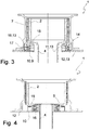
- the Fig. 3 shows a further embodiment of the water turbine 1.
- the rotor 2 designed as a hollow cylinder, sits on the flange 15 of the shaft 4.
- This flange 15 is placed on the running ring 10, in this embodiment the inner ring, of the torque bearing 9, which in turn rests with a stationary outer ring 17 on the carrier plate 12.
- a further outer ring plate 18 as well as the carrier plate 12 and the ring plate 11 are used
- the Fig. 4 shows yet another embodiment of the water turbine 1.
- the moment bearing 9 is otherwise similar in basic structure to that in FIG Fig. 2 smaller in diameter.
- the rotor 2 designed as a hollow cylinder, sits on the flange 15 of the shaft 4. This flange is placed on the running ring 10 of the torque bearing 9, which in turn sits with the stationary inner ring 16 on the carrier plate 12.
- the Fig. 5 shows an embodiment with a plain bearing 19.
- the rotor 2 is supported on a running ring 20 via the flange 15.
- the running ring 20 has an axial sliding surface 21 and a conical sliding surface 22 through which the torque bearing 23 is guided radially and axially upwards.
- the forces acting axially downwards, which are generated by the blades of the turbine during operation, are supported by the axial sliding surface 21.
- An oil pan 13 is also formed here by the annular plate 11, the housing 7 and the carrier plate 12.
- a moment bearing 23 as a sliding bearing 19 can support very high axial forces.
- the production of the plain bearing 19 is more cost-effective than a corresponding roller bearing as a moment bearing.
Landscapes
- Engineering & Computer Science (AREA)
- General Engineering & Computer Science (AREA)
- Mechanical Engineering (AREA)
- Chemical & Material Sciences (AREA)
- Combustion & Propulsion (AREA)
- Hydraulic Turbines (AREA)
Applications Claiming Priority (1)
| Application Number | Priority Date | Filing Date | Title |
|---|---|---|---|
| DE102020112739 | 2020-05-11 |
Publications (2)
| Publication Number | Publication Date |
|---|---|
| EP3910192A1 true EP3910192A1 (fr) | 2021-11-17 |
| EP3910192B1 EP3910192B1 (fr) | 2023-08-16 |
Family
ID=75914312
Family Applications (1)
| Application Number | Title | Priority Date | Filing Date |
|---|---|---|---|
| EP21173428.0A Active EP3910192B1 (fr) | 2020-05-11 | 2021-05-11 | Turbine à eau et/ou pompe à eau |
Country Status (2)
| Country | Link |
|---|---|
| EP (1) | EP3910192B1 (fr) |
| DE (1) | DE102021112348A1 (fr) |
Citations (7)
| Publication number | Priority date | Publication date | Assignee | Title |
|---|---|---|---|---|
| US2733892A (en) * | 1956-02-07 | Thrust bearings | ||
| DE2821458A1 (de) * | 1977-05-25 | 1978-12-21 | Escher Wyss Gmbh | Hydroelektrischer maschinensatz |
| EP0940611A2 (fr) * | 1998-03-04 | 1999-09-08 | Itt Manufacturing Enterprises, Inc. | Dispositif d'étanchéité pour pompe |
| DE102006043946A1 (de) | 2006-09-14 | 2008-03-27 | Oswald Elektromotoren Gmbh | Turbinenvorrichtung |
| CH701118A2 (fr) * | 2009-05-26 | 2010-11-30 | Jean Christophe Maillard De La Morandais | Turbine à hélice suspendue pour chute d'eau de faible hauteur. |
| DE102010018555A1 (de) | 2010-04-28 | 2011-11-03 | Aktiebolaget Skf | Turbinengenerator |
| US20130183178A1 (en) * | 2010-09-13 | 2013-07-18 | Zenit International S. A. | Cooling systems for submersible pumps |
-
2021
- 2021-05-11 EP EP21173428.0A patent/EP3910192B1/fr active Active
- 2021-05-11 DE DE102021112348.8A patent/DE102021112348A1/de not_active Withdrawn
Patent Citations (7)
| Publication number | Priority date | Publication date | Assignee | Title |
|---|---|---|---|---|
| US2733892A (en) * | 1956-02-07 | Thrust bearings | ||
| DE2821458A1 (de) * | 1977-05-25 | 1978-12-21 | Escher Wyss Gmbh | Hydroelektrischer maschinensatz |
| EP0940611A2 (fr) * | 1998-03-04 | 1999-09-08 | Itt Manufacturing Enterprises, Inc. | Dispositif d'étanchéité pour pompe |
| DE102006043946A1 (de) | 2006-09-14 | 2008-03-27 | Oswald Elektromotoren Gmbh | Turbinenvorrichtung |
| CH701118A2 (fr) * | 2009-05-26 | 2010-11-30 | Jean Christophe Maillard De La Morandais | Turbine à hélice suspendue pour chute d'eau de faible hauteur. |
| DE102010018555A1 (de) | 2010-04-28 | 2011-11-03 | Aktiebolaget Skf | Turbinengenerator |
| US20130183178A1 (en) * | 2010-09-13 | 2013-07-18 | Zenit International S. A. | Cooling systems for submersible pumps |
Also Published As
| Publication number | Publication date |
|---|---|
| DE102021112348A1 (de) | 2021-11-11 |
| EP3910192B1 (fr) | 2023-08-16 |
Similar Documents
| Publication | Publication Date | Title |
|---|---|---|
| EP2067271B1 (fr) | Appareil à turbine | |
| DE102008064815B3 (de) | Spindelmotor mit fluiddynamischem Lagersystem und feststehender WeIle | |
| DE102007061185B4 (de) | Tauchende Energieerzeugungsanlage, angetrieben durch eine Wasserströmung | |
| DE102013211710C5 (de) | Windkraftanlage mit einem Gleitlager | |
| EP3894716B1 (fr) | Nacelle pour une éolienne | |
| DE19853790A1 (de) | Windkraftanlage | |
| DE10345907B4 (de) | Hydrodynamisches Lager, Spindelmotor und Festplattenlaufwerk | |
| WO2010072497A2 (fr) | Machine électrique à bouclier d'appui de rotor | |
| EP2310664A2 (fr) | Centrale immergee et son procede de montage | |
| DE102004046563B4 (de) | Windenergieanlage mit vollintegriertem Maschinensatz | |
| WO2009094998A2 (fr) | Ensemble palier lubrifié à l'eau | |
| DE2138152A1 (de) | Turbomolekularvakuumpumpe | |
| EP2403750B1 (fr) | Machine a deplacement non-positif, avec un boitier a etancheite amelioree | |
| DE102008024049B4 (de) | Lageranordnung mit einer Vorspanneinrichtung | |
| EP3910192B1 (fr) | Turbine à eau et/ou pompe à eau | |
| EP1223359A1 (fr) | Manchon étanche pour le palier d'un générateur sub-aquatique | |
| DE102021112354A1 (de) | Wasserturbine und/oder Wasserpumpe | |
| DE102010024153A1 (de) | Windkraftanlage | |
| WO2018041667A1 (fr) | Moyeu pour pale d'hélice d'une éolienne, et éolienne doté de ce moyeu | |
| DE10342808B4 (de) | Turbolader mit Schmiermittelaustrageinrichtung | |
| DE3440635C2 (fr) | ||
| EP2853019B1 (fr) | Machine électrique | |
| DE102017118010A1 (de) | Generator für eine Windenergieanlage und Windenergieanlage mit selbigem | |
| WO2024056906A1 (fr) | Système d'éolienne et ensemble palier | |
| DE102018120810A1 (de) | Lageranordnung eines Rotors einer Windkraftanlage und Windkraftanlage |
Legal Events
| Date | Code | Title | Description |
|---|---|---|---|
| PUAI | Public reference made under article 153(3) epc to a published international application that has entered the european phase |
Free format text: ORIGINAL CODE: 0009012 |
|
| STAA | Information on the status of an ep patent application or granted ep patent |
Free format text: STATUS: THE APPLICATION HAS BEEN PUBLISHED |
|
| AK | Designated contracting states |
Kind code of ref document: A1 Designated state(s): AL AT BE BG CH CY CZ DE DK EE ES FI FR GB GR HR HU IE IS IT LI LT LU LV MC MK MT NL NO PL PT RO RS SE SI SK SM TR |
|
| B565 | Issuance of search results under rule 164(2) epc |
Effective date: 20211008 |
|
| STAA | Information on the status of an ep patent application or granted ep patent |
Free format text: STATUS: REQUEST FOR EXAMINATION WAS MADE |
|
| 17P | Request for examination filed |
Effective date: 20220517 |
|
| RBV | Designated contracting states (corrected) |
Designated state(s): AL AT BE BG CH CY CZ DE DK EE ES FI FR GB GR HR HU IE IS IT LI LT LU LV MC MK MT NL NO PL PT RO RS SE SI SK SM TR |
|
| GRAP | Despatch of communication of intention to grant a patent |
Free format text: ORIGINAL CODE: EPIDOSNIGR1 |
|
| STAA | Information on the status of an ep patent application or granted ep patent |
Free format text: STATUS: GRANT OF PATENT IS INTENDED |
|
| RIC1 | Information provided on ipc code assigned before grant |
Ipc: F16C 35/077 20060101ALI20230117BHEP Ipc: F16C 35/073 20060101ALI20230117BHEP Ipc: F16C 33/66 20060101ALI20230117BHEP Ipc: F16C 35/067 20060101ALI20230117BHEP Ipc: F16C 35/063 20060101ALI20230117BHEP Ipc: F16C 19/18 20060101ALI20230117BHEP Ipc: F16C 17/10 20060101ALI20230117BHEP Ipc: F03B 11/06 20060101AFI20230117BHEP |
|
| INTG | Intention to grant announced |
Effective date: 20230222 |
|
| P01 | Opt-out of the competence of the unified patent court (upc) registered |
Effective date: 20230523 |
|
| GRAS | Grant fee paid |
Free format text: ORIGINAL CODE: EPIDOSNIGR3 |
|
| GRAA | (expected) grant |
Free format text: ORIGINAL CODE: 0009210 |
|
| STAA | Information on the status of an ep patent application or granted ep patent |
Free format text: STATUS: THE PATENT HAS BEEN GRANTED |
|
| AK | Designated contracting states |
Kind code of ref document: B1 Designated state(s): AL AT BE BG CH CY CZ DE DK EE ES FI FR GB GR HR HU IE IS IT LI LT LU LV MC MK MT NL NO PL PT RO RS SE SI SK SM TR |
|
| REG | Reference to a national code |
Ref country code: CH Ref legal event code: EP Ref country code: DE Ref legal event code: R096 Ref document number: 502021001247 Country of ref document: DE |
|
| REG | Reference to a national code |
Ref country code: IE Ref legal event code: FG4D Free format text: LANGUAGE OF EP DOCUMENT: GERMAN |
|
| REG | Reference to a national code |
Ref country code: NO Ref legal event code: T2 Effective date: 20230816 |
|
| REG | Reference to a national code |
Ref country code: LT Ref legal event code: MG9D |
|
| REG | Reference to a national code |
Ref country code: SE Ref legal event code: TRGR |
|
| REG | Reference to a national code |
Ref country code: NL Ref legal event code: MP Effective date: 20230816 |
|
| PG25 | Lapsed in a contracting state [announced via postgrant information from national office to epo] |
Ref country code: GR Free format text: LAPSE BECAUSE OF FAILURE TO SUBMIT A TRANSLATION OF THE DESCRIPTION OR TO PAY THE FEE WITHIN THE PRESCRIBED TIME-LIMIT Effective date: 20231117 |
|
| PG25 | Lapsed in a contracting state [announced via postgrant information from national office to epo] |
Ref country code: IS Free format text: LAPSE BECAUSE OF FAILURE TO SUBMIT A TRANSLATION OF THE DESCRIPTION OR TO PAY THE FEE WITHIN THE PRESCRIBED TIME-LIMIT Effective date: 20231216 |
|
| PG25 | Lapsed in a contracting state [announced via postgrant information from national office to epo] |
Ref country code: RS Free format text: LAPSE BECAUSE OF FAILURE TO SUBMIT A TRANSLATION OF THE DESCRIPTION OR TO PAY THE FEE WITHIN THE PRESCRIBED TIME-LIMIT Effective date: 20230816 Ref country code: PT Free format text: LAPSE BECAUSE OF FAILURE TO SUBMIT A TRANSLATION OF THE DESCRIPTION OR TO PAY THE FEE WITHIN THE PRESCRIBED TIME-LIMIT Effective date: 20231218 Ref country code: NL Free format text: LAPSE BECAUSE OF FAILURE TO SUBMIT A TRANSLATION OF THE DESCRIPTION OR TO PAY THE FEE WITHIN THE PRESCRIBED TIME-LIMIT Effective date: 20230816 Ref country code: LV Free format text: LAPSE BECAUSE OF FAILURE TO SUBMIT A TRANSLATION OF THE DESCRIPTION OR TO PAY THE FEE WITHIN THE PRESCRIBED TIME-LIMIT Effective date: 20230816 Ref country code: LT Free format text: LAPSE BECAUSE OF FAILURE TO SUBMIT A TRANSLATION OF THE DESCRIPTION OR TO PAY THE FEE WITHIN THE PRESCRIBED TIME-LIMIT Effective date: 20230816 Ref country code: IS Free format text: LAPSE BECAUSE OF FAILURE TO SUBMIT A TRANSLATION OF THE DESCRIPTION OR TO PAY THE FEE WITHIN THE PRESCRIBED TIME-LIMIT Effective date: 20231216 Ref country code: HR Free format text: LAPSE BECAUSE OF FAILURE TO SUBMIT A TRANSLATION OF THE DESCRIPTION OR TO PAY THE FEE WITHIN THE PRESCRIBED TIME-LIMIT Effective date: 20230816 Ref country code: GR Free format text: LAPSE BECAUSE OF FAILURE TO SUBMIT A TRANSLATION OF THE DESCRIPTION OR TO PAY THE FEE WITHIN THE PRESCRIBED TIME-LIMIT Effective date: 20231117 Ref country code: FI Free format text: LAPSE BECAUSE OF FAILURE TO SUBMIT A TRANSLATION OF THE DESCRIPTION OR TO PAY THE FEE WITHIN THE PRESCRIBED TIME-LIMIT Effective date: 20230816 |
|
| PG25 | Lapsed in a contracting state [announced via postgrant information from national office to epo] |
Ref country code: PL Free format text: LAPSE BECAUSE OF FAILURE TO SUBMIT A TRANSLATION OF THE DESCRIPTION OR TO PAY THE FEE WITHIN THE PRESCRIBED TIME-LIMIT Effective date: 20230816 |
|
| PG25 | Lapsed in a contracting state [announced via postgrant information from national office to epo] |
Ref country code: ES Free format text: LAPSE BECAUSE OF FAILURE TO SUBMIT A TRANSLATION OF THE DESCRIPTION OR TO PAY THE FEE WITHIN THE PRESCRIBED TIME-LIMIT Effective date: 20230816 |
|
| PG25 | Lapsed in a contracting state [announced via postgrant information from national office to epo] |
Ref country code: SM Free format text: LAPSE BECAUSE OF FAILURE TO SUBMIT A TRANSLATION OF THE DESCRIPTION OR TO PAY THE FEE WITHIN THE PRESCRIBED TIME-LIMIT Effective date: 20230816 Ref country code: RO Free format text: LAPSE BECAUSE OF FAILURE TO SUBMIT A TRANSLATION OF THE DESCRIPTION OR TO PAY THE FEE WITHIN THE PRESCRIBED TIME-LIMIT Effective date: 20230816 Ref country code: ES Free format text: LAPSE BECAUSE OF FAILURE TO SUBMIT A TRANSLATION OF THE DESCRIPTION OR TO PAY THE FEE WITHIN THE PRESCRIBED TIME-LIMIT Effective date: 20230816 Ref country code: EE Free format text: LAPSE BECAUSE OF FAILURE TO SUBMIT A TRANSLATION OF THE DESCRIPTION OR TO PAY THE FEE WITHIN THE PRESCRIBED TIME-LIMIT Effective date: 20230816 Ref country code: DK Free format text: LAPSE BECAUSE OF FAILURE TO SUBMIT A TRANSLATION OF THE DESCRIPTION OR TO PAY THE FEE WITHIN THE PRESCRIBED TIME-LIMIT Effective date: 20230816 Ref country code: CZ Free format text: LAPSE BECAUSE OF FAILURE TO SUBMIT A TRANSLATION OF THE DESCRIPTION OR TO PAY THE FEE WITHIN THE PRESCRIBED TIME-LIMIT Effective date: 20230816 Ref country code: SK Free format text: LAPSE BECAUSE OF FAILURE TO SUBMIT A TRANSLATION OF THE DESCRIPTION OR TO PAY THE FEE WITHIN THE PRESCRIBED TIME-LIMIT Effective date: 20230816 |
|
| REG | Reference to a national code |
Ref country code: DE Ref legal event code: R097 Ref document number: 502021001247 Country of ref document: DE |
|
| PLBE | No opposition filed within time limit |
Free format text: ORIGINAL CODE: 0009261 |
|
| STAA | Information on the status of an ep patent application or granted ep patent |
Free format text: STATUS: NO OPPOSITION FILED WITHIN TIME LIMIT |
|
| 26N | No opposition filed |
Effective date: 20240517 |
|
| PG25 | Lapsed in a contracting state [announced via postgrant information from national office to epo] |
Ref country code: IT Free format text: LAPSE BECAUSE OF FAILURE TO SUBMIT A TRANSLATION OF THE DESCRIPTION OR TO PAY THE FEE WITHIN THE PRESCRIBED TIME-LIMIT Effective date: 20230816 Ref country code: SI Free format text: LAPSE BECAUSE OF FAILURE TO SUBMIT A TRANSLATION OF THE DESCRIPTION OR TO PAY THE FEE WITHIN THE PRESCRIBED TIME-LIMIT Effective date: 20230816 |
|
| PG25 | Lapsed in a contracting state [announced via postgrant information from national office to epo] |
Ref country code: BG Free format text: LAPSE BECAUSE OF FAILURE TO SUBMIT A TRANSLATION OF THE DESCRIPTION OR TO PAY THE FEE WITHIN THE PRESCRIBED TIME-LIMIT Effective date: 20230816 |
|
| PG25 | Lapsed in a contracting state [announced via postgrant information from national office to epo] |
Ref country code: BG Free format text: LAPSE BECAUSE OF FAILURE TO SUBMIT A TRANSLATION OF THE DESCRIPTION OR TO PAY THE FEE WITHIN THE PRESCRIBED TIME-LIMIT Effective date: 20230816 |
|
| REG | Reference to a national code |
Ref country code: CH Ref legal event code: PL |
|
| PG25 | Lapsed in a contracting state [announced via postgrant information from national office to epo] |
Ref country code: MC Free format text: LAPSE BECAUSE OF FAILURE TO SUBMIT A TRANSLATION OF THE DESCRIPTION OR TO PAY THE FEE WITHIN THE PRESCRIBED TIME-LIMIT Effective date: 20230816 |
|
| PG25 | Lapsed in a contracting state [announced via postgrant information from national office to epo] |
Ref country code: LU Free format text: LAPSE BECAUSE OF NON-PAYMENT OF DUE FEES Effective date: 20240511 |
|
| PG25 | Lapsed in a contracting state [announced via postgrant information from national office to epo] |
Ref country code: MC Free format text: LAPSE BECAUSE OF FAILURE TO SUBMIT A TRANSLATION OF THE DESCRIPTION OR TO PAY THE FEE WITHIN THE PRESCRIBED TIME-LIMIT Effective date: 20230816 Ref country code: LU Free format text: LAPSE BECAUSE OF NON-PAYMENT OF DUE FEES Effective date: 20240511 Ref country code: CH Free format text: LAPSE BECAUSE OF NON-PAYMENT OF DUE FEES Effective date: 20240531 |
|
| REG | Reference to a national code |
Ref country code: BE Ref legal event code: MM Effective date: 20240531 |
|
| PG25 | Lapsed in a contracting state [announced via postgrant information from national office to epo] |
Ref country code: IE Free format text: LAPSE BECAUSE OF NON-PAYMENT OF DUE FEES Effective date: 20240511 |
|
| PG25 | Lapsed in a contracting state [announced via postgrant information from national office to epo] |
Ref country code: BE Free format text: LAPSE BECAUSE OF NON-PAYMENT OF DUE FEES Effective date: 20240531 |
|
| PGFP | Annual fee paid to national office [announced via postgrant information from national office to epo] |
Ref country code: GB Payment date: 20250522 Year of fee payment: 5 |
|
| PGFP | Annual fee paid to national office [announced via postgrant information from national office to epo] |
Ref country code: NO Payment date: 20250520 Year of fee payment: 5 |
|
| PGFP | Annual fee paid to national office [announced via postgrant information from national office to epo] |
Ref country code: FR Payment date: 20250523 Year of fee payment: 5 |
|
| PGFP | Annual fee paid to national office [announced via postgrant information from national office to epo] |
Ref country code: AT Payment date: 20250721 Year of fee payment: 5 |
|
| PGFP | Annual fee paid to national office [announced via postgrant information from national office to epo] |
Ref country code: SE Payment date: 20250522 Year of fee payment: 5 |
|
| PG25 | Lapsed in a contracting state [announced via postgrant information from national office to epo] |
Ref country code: CY Free format text: LAPSE BECAUSE OF FAILURE TO SUBMIT A TRANSLATION OF THE DESCRIPTION OR TO PAY THE FEE WITHIN THE PRESCRIBED TIME-LIMIT; INVALID AB INITIO Effective date: 20210511 |
|
| PG25 | Lapsed in a contracting state [announced via postgrant information from national office to epo] |
Ref country code: HU Free format text: LAPSE BECAUSE OF FAILURE TO SUBMIT A TRANSLATION OF THE DESCRIPTION OR TO PAY THE FEE WITHIN THE PRESCRIBED TIME-LIMIT; INVALID AB INITIO Effective date: 20210511 |
|
| PGFP | Annual fee paid to national office [announced via postgrant information from national office to epo] |
Ref country code: DE Payment date: 20251128 Year of fee payment: 5 |