EP3910193B1 - Procédés de fabrication de pale de rotor d'éolienne - Google Patents
Procédés de fabrication de pale de rotor d'éolienne Download PDFInfo
- Publication number
- EP3910193B1 EP3910193B1 EP20173843.2A EP20173843A EP3910193B1 EP 3910193 B1 EP3910193 B1 EP 3910193B1 EP 20173843 A EP20173843 A EP 20173843A EP 3910193 B1 EP3910193 B1 EP 3910193B1
- Authority
- EP
- European Patent Office
- Prior art keywords
- mould
- rotor blade
- leading
- edge
- fin
- Prior art date
- Legal status (The legal status is an assumption and is not a legal conclusion. Google has not performed a legal analysis and makes no representation as to the accuracy of the status listed.)
- Active
Links
Images



Classifications
-
- B—PERFORMING OPERATIONS; TRANSPORTING
- B29—WORKING OF PLASTICS; WORKING OF SUBSTANCES IN A PLASTIC STATE IN GENERAL
- B29D—PRODUCING PARTICULAR ARTICLES FROM PLASTICS OR FROM SUBSTANCES IN A PLASTIC STATE
- B29D99/00—Subject matter not provided for in other groups of this subclass
- B29D99/0025—Producing blades or the like, e.g. blades for turbines, propellers, or wings
-
- F—MECHANICAL ENGINEERING; LIGHTING; HEATING; WEAPONS; BLASTING
- F03—MACHINES OR ENGINES FOR LIQUIDS; WIND, SPRING, OR WEIGHT MOTORS; PRODUCING MECHANICAL POWER OR A REACTIVE PROPULSIVE THRUST, NOT OTHERWISE PROVIDED FOR
- F03D—WIND MOTORS
- F03D3/00—Wind motors with rotation axis substantially perpendicular to the air flow entering the rotor
- F03D3/06—Rotors
- F03D3/062—Rotors characterised by their construction elements
-
- F—MECHANICAL ENGINEERING; LIGHTING; HEATING; WEAPONS; BLASTING
- F03—MACHINES OR ENGINES FOR LIQUIDS; WIND, SPRING, OR WEIGHT MOTORS; PRODUCING MECHANICAL POWER OR A REACTIVE PROPULSIVE THRUST, NOT OTHERWISE PROVIDED FOR
- F03D—WIND MOTORS
- F03D1/00—Wind motors with rotation axis substantially parallel to the air flow entering the rotor
- F03D1/06—Rotors
- F03D1/065—Rotors characterised by their construction elements
- F03D1/0675—Rotors characterised by their construction elements of the blades
-
- B—PERFORMING OPERATIONS; TRANSPORTING
- B29—WORKING OF PLASTICS; WORKING OF SUBSTANCES IN A PLASTIC STATE IN GENERAL
- B29C—SHAPING OR JOINING OF PLASTICS; SHAPING OF MATERIAL IN A PLASTIC STATE, NOT OTHERWISE PROVIDED FOR; AFTER-TREATMENT OF THE SHAPED PRODUCTS, e.g. REPAIRING
- B29C33/00—Moulds or cores; Details thereof or accessories therefor
- B29C33/30—Mounting, exchanging or centering
- B29C33/306—Exchangeable mould parts, e.g. cassette moulds, mould inserts
-
- B—PERFORMING OPERATIONS; TRANSPORTING
- B29—WORKING OF PLASTICS; WORKING OF SUBSTANCES IN A PLASTIC STATE IN GENERAL
- B29C—SHAPING OR JOINING OF PLASTICS; SHAPING OF MATERIAL IN A PLASTIC STATE, NOT OTHERWISE PROVIDED FOR; AFTER-TREATMENT OF THE SHAPED PRODUCTS, e.g. REPAIRING
- B29C33/00—Moulds or cores; Details thereof or accessories therefor
- B29C33/38—Moulds or cores; Details thereof or accessories therefor characterised by the material or the manufacturing process
- B29C33/3842—Manufacturing moulds, e.g. shaping the mould surface by machining
-
- B—PERFORMING OPERATIONS; TRANSPORTING
- B29—WORKING OF PLASTICS; WORKING OF SUBSTANCES IN A PLASTIC STATE IN GENERAL
- B29C—SHAPING OR JOINING OF PLASTICS; SHAPING OF MATERIAL IN A PLASTIC STATE, NOT OTHERWISE PROVIDED FOR; AFTER-TREATMENT OF THE SHAPED PRODUCTS, e.g. REPAIRING
- B29C70/00—Shaping composites, i.e. plastics material comprising reinforcements, fillers or preformed parts, e.g. inserts
- B29C70/04—Shaping composites, i.e. plastics material comprising reinforcements, fillers or preformed parts, e.g. inserts comprising reinforcements only, e.g. self-reinforcing plastics
- B29C70/28—Shaping operations therefor
- B29C70/30—Shaping by lay-up, i.e. applying fibres, tape or broadsheet on a mould, former or core; Shaping by spray-up, i.e. spraying of fibres on a mould, former or core
-
- B—PERFORMING OPERATIONS; TRANSPORTING
- B29—WORKING OF PLASTICS; WORKING OF SUBSTANCES IN A PLASTIC STATE IN GENERAL
- B29C—SHAPING OR JOINING OF PLASTICS; SHAPING OF MATERIAL IN A PLASTIC STATE, NOT OTHERWISE PROVIDED FOR; AFTER-TREATMENT OF THE SHAPED PRODUCTS, e.g. REPAIRING
- B29C70/00—Shaping composites, i.e. plastics material comprising reinforcements, fillers or preformed parts, e.g. inserts
- B29C70/04—Shaping composites, i.e. plastics material comprising reinforcements, fillers or preformed parts, e.g. inserts comprising reinforcements only, e.g. self-reinforcing plastics
- B29C70/28—Shaping operations therefor
- B29C70/30—Shaping by lay-up, i.e. applying fibres, tape or broadsheet on a mould, former or core; Shaping by spray-up, i.e. spraying of fibres on a mould, former or core
- B29C70/302—Details of the edges of fibre composites, e.g. edge finishing or means to avoid delamination
-
- B—PERFORMING OPERATIONS; TRANSPORTING
- B29—WORKING OF PLASTICS; WORKING OF SUBSTANCES IN A PLASTIC STATE IN GENERAL
- B29C—SHAPING OR JOINING OF PLASTICS; SHAPING OF MATERIAL IN A PLASTIC STATE, NOT OTHERWISE PROVIDED FOR; AFTER-TREATMENT OF THE SHAPED PRODUCTS, e.g. REPAIRING
- B29C70/00—Shaping composites, i.e. plastics material comprising reinforcements, fillers or preformed parts, e.g. inserts
- B29C70/04—Shaping composites, i.e. plastics material comprising reinforcements, fillers or preformed parts, e.g. inserts comprising reinforcements only, e.g. self-reinforcing plastics
- B29C70/28—Shaping operations therefor
- B29C70/40—Shaping or impregnating by compression not applied
- B29C70/42—Shaping or impregnating by compression not applied for producing articles of definite length, i.e. discrete articles
- B29C70/46—Shaping or impregnating by compression not applied for producing articles of definite length, i.e. discrete articles using matched moulds, e.g. for deforming sheet moulding compounds [SMC] or prepregs
- B29C70/48—Shaping or impregnating by compression not applied for producing articles of definite length, i.e. discrete articles using matched moulds, e.g. for deforming sheet moulding compounds [SMC] or prepregs and impregnating the reinforcements in the closed mould, e.g. resin transfer moulding [RTM], e.g. by vacuum
-
- B—PERFORMING OPERATIONS; TRANSPORTING
- B29—WORKING OF PLASTICS; WORKING OF SUBSTANCES IN A PLASTIC STATE IN GENERAL
- B29C—SHAPING OR JOINING OF PLASTICS; SHAPING OF MATERIAL IN A PLASTIC STATE, NOT OTHERWISE PROVIDED FOR; AFTER-TREATMENT OF THE SHAPED PRODUCTS, e.g. REPAIRING
- B29C70/00—Shaping composites, i.e. plastics material comprising reinforcements, fillers or preformed parts, e.g. inserts
- B29C70/04—Shaping composites, i.e. plastics material comprising reinforcements, fillers or preformed parts, e.g. inserts comprising reinforcements only, e.g. self-reinforcing plastics
- B29C70/28—Shaping operations therefor
- B29C70/54—Component parts, details or accessories; Auxiliary operations, e.g. feeding or storage of prepregs or SMC after impregnation or during ageing
-
- B—PERFORMING OPERATIONS; TRANSPORTING
- B29—WORKING OF PLASTICS; WORKING OF SUBSTANCES IN A PLASTIC STATE IN GENERAL
- B29C—SHAPING OR JOINING OF PLASTICS; SHAPING OF MATERIAL IN A PLASTIC STATE, NOT OTHERWISE PROVIDED FOR; AFTER-TREATMENT OF THE SHAPED PRODUCTS, e.g. REPAIRING
- B29C70/00—Shaping composites, i.e. plastics material comprising reinforcements, fillers or preformed parts, e.g. inserts
- B29C70/68—Shaping composites, i.e. plastics material comprising reinforcements, fillers or preformed parts, e.g. inserts by incorporating or moulding on preformed parts, e.g. inserts or layers, e.g. foam blocks
- B29C70/70—Completely encapsulating inserts
-
- B—PERFORMING OPERATIONS; TRANSPORTING
- B29—WORKING OF PLASTICS; WORKING OF SUBSTANCES IN A PLASTIC STATE IN GENERAL
- B29D—PRODUCING PARTICULAR ARTICLES FROM PLASTICS OR FROM SUBSTANCES IN A PLASTIC STATE
- B29D99/00—Subject matter not provided for in other groups of this subclass
- B29D99/0025—Producing blades or the like, e.g. blades for turbines, propellers, or wings
- B29D99/0028—Producing blades or the like, e.g. blades for turbines, propellers, or wings hollow blades
-
- F—MECHANICAL ENGINEERING; LIGHTING; HEATING; WEAPONS; BLASTING
- F03—MACHINES OR ENGINES FOR LIQUIDS; WIND, SPRING, OR WEIGHT MOTORS; PRODUCING MECHANICAL POWER OR A REACTIVE PROPULSIVE THRUST, NOT OTHERWISE PROVIDED FOR
- F03D—WIND MOTORS
- F03D1/00—Wind motors with rotation axis substantially parallel to the air flow entering the rotor
- F03D1/06—Rotors
- F03D1/0608—Rotors characterised by their aerodynamic shape
- F03D1/0633—Rotors characterised by their aerodynamic shape of the blades
-
- B—PERFORMING OPERATIONS; TRANSPORTING
- B29—WORKING OF PLASTICS; WORKING OF SUBSTANCES IN A PLASTIC STATE IN GENERAL
- B29L—INDEXING SCHEME ASSOCIATED WITH SUBCLASS B29C, RELATING TO PARTICULAR ARTICLES
- B29L2031/00—Other particular articles
- B29L2031/08—Blades for rotors, stators, fans, turbines or the like, e.g. screw propellers
- B29L2031/082—Blades, e.g. for helicopters
- B29L2031/085—Wind turbine blades
-
- F—MECHANICAL ENGINEERING; LIGHTING; HEATING; WEAPONS; BLASTING
- F05—INDEXING SCHEMES RELATING TO ENGINES OR PUMPS IN VARIOUS SUBCLASSES OF CLASSES F01-F04
- F05B—INDEXING SCHEME RELATING TO WIND, SPRING, WEIGHT, INERTIA OR LIKE MOTORS, TO MACHINES OR ENGINES FOR LIQUIDS COVERED BY SUBCLASSES F03B, F03D AND F03G
- F05B2220/00—Application
- F05B2220/30—Application in turbines
-
- F—MECHANICAL ENGINEERING; LIGHTING; HEATING; WEAPONS; BLASTING
- F05—INDEXING SCHEMES RELATING TO ENGINES OR PUMPS IN VARIOUS SUBCLASSES OF CLASSES F01-F04
- F05B—INDEXING SCHEME RELATING TO WIND, SPRING, WEIGHT, INERTIA OR LIKE MOTORS, TO MACHINES OR ENGINES FOR LIQUIDS COVERED BY SUBCLASSES F03B, F03D AND F03G
- F05B2230/00—Manufacture
- F05B2230/20—Manufacture essentially without removing material
-
- F—MECHANICAL ENGINEERING; LIGHTING; HEATING; WEAPONS; BLASTING
- F05—INDEXING SCHEMES RELATING TO ENGINES OR PUMPS IN VARIOUS SUBCLASSES OF CLASSES F01-F04
- F05B—INDEXING SCHEME RELATING TO WIND, SPRING, WEIGHT, INERTIA OR LIKE MOTORS, TO MACHINES OR ENGINES FOR LIQUIDS COVERED BY SUBCLASSES F03B, F03D AND F03G
- F05B2240/00—Components
- F05B2240/20—Rotors
- F05B2240/30—Characteristics of rotor blades, i.e. of any element transforming dynamic fluid energy to or from rotational energy and being attached to a rotor
- F05B2240/303—Details of the leading edge
-
- F—MECHANICAL ENGINEERING; LIGHTING; HEATING; WEAPONS; BLASTING
- F05—INDEXING SCHEMES RELATING TO ENGINES OR PUMPS IN VARIOUS SUBCLASSES OF CLASSES F01-F04
- F05B—INDEXING SCHEME RELATING TO WIND, SPRING, WEIGHT, INERTIA OR LIKE MOTORS, TO MACHINES OR ENGINES FOR LIQUIDS COVERED BY SUBCLASSES F03B, F03D AND F03G
- F05B2260/00—Function
- F05B2260/96—Preventing, counteracting or reducing vibration or noise
-
- Y—GENERAL TAGGING OF NEW TECHNOLOGICAL DEVELOPMENTS; GENERAL TAGGING OF CROSS-SECTIONAL TECHNOLOGIES SPANNING OVER SEVERAL SECTIONS OF THE IPC; TECHNICAL SUBJECTS COVERED BY FORMER USPC CROSS-REFERENCE ART COLLECTIONS [XRACs] AND DIGESTS
- Y02—TECHNOLOGIES OR APPLICATIONS FOR MITIGATION OR ADAPTATION AGAINST CLIMATE CHANGE
- Y02E—REDUCTION OF GREENHOUSE GAS [GHG] EMISSIONS, RELATED TO ENERGY GENERATION, TRANSMISSION OR DISTRIBUTION
- Y02E10/00—Energy generation through renewable energy sources
- Y02E10/70—Wind energy
- Y02E10/72—Wind turbines with rotation axis in wind direction
-
- Y—GENERAL TAGGING OF NEW TECHNOLOGICAL DEVELOPMENTS; GENERAL TAGGING OF CROSS-SECTIONAL TECHNOLOGIES SPANNING OVER SEVERAL SECTIONS OF THE IPC; TECHNICAL SUBJECTS COVERED BY FORMER USPC CROSS-REFERENCE ART COLLECTIONS [XRACs] AND DIGESTS
- Y02—TECHNOLOGIES OR APPLICATIONS FOR MITIGATION OR ADAPTATION AGAINST CLIMATE CHANGE
- Y02E—REDUCTION OF GREENHOUSE GAS [GHG] EMISSIONS, RELATED TO ENERGY GENERATION, TRANSMISSION OR DISTRIBUTION
- Y02E10/00—Energy generation through renewable energy sources
- Y02E10/70—Wind energy
- Y02E10/74—Wind turbines with rotation axis perpendicular to the wind direction
-
- Y—GENERAL TAGGING OF NEW TECHNOLOGICAL DEVELOPMENTS; GENERAL TAGGING OF CROSS-SECTIONAL TECHNOLOGIES SPANNING OVER SEVERAL SECTIONS OF THE IPC; TECHNICAL SUBJECTS COVERED BY FORMER USPC CROSS-REFERENCE ART COLLECTIONS [XRACs] AND DIGESTS
- Y02—TECHNOLOGIES OR APPLICATIONS FOR MITIGATION OR ADAPTATION AGAINST CLIMATE CHANGE
- Y02P—CLIMATE CHANGE MITIGATION TECHNOLOGIES IN THE PRODUCTION OR PROCESSING OF GOODS
- Y02P70/00—Climate change mitigation technologies in the production process for final industrial or consumer products
- Y02P70/50—Manufacturing or production processes characterised by the final manufactured product
Definitions
- the invention describes a method of manufacturing a wind turbine rotor blade.
- a fin shall be understood to be a curved part mounted over the leading edge, extending some distance into the suction side and pressure side of the rotor blade, and extending radially outward from the body of the rotor blade.
- a fin is preferably shaped so that a cross-section through it and the rotor blade would have the shape of an airfoil.
- the fins can be individually attached to the rotor blade body, or can be mounted on a curved carrier as part of a pre-assembled part that can be attached along the leading edge of a rotor blade.
- Such faults in turn can lead to catastrophic damage in the event of a lightning strike to the rotor blade.
- the structural damage may be so severe that the rotor blade needs to be repaired.
- Such maintenance work results in downtime of the wind turbine and further reduces the annual energy output.
- pits or scratches in the otherwise smooth rotor blade will reduce the aerodynamic performance of the rotor blade, and may have a noticeable negative effect on the annual energy output of the wind turbine.
- a finned leading edge is more effective than a simple protective coating applied over the leading edge, because the fins serve to minimize the surface area that is exposed to direct particle impact.
- the method comprises the steps of preparing a mould by forming a partial negative leading-edge profile in a first mould part, which partial negative leading-edge profile comprises a plurality of first indentations along a leading edge region of the first mould part; and also by forming a partial negative leading-edge profile in an second mould half, which partial negative leading-edge profile comprises a complementary plurality of second indentations along a leading edge region of the second mould half.
- the shape of a complete indentation comprising a first indentation and a complementary second indentation is the negative shape of a leading-edge fin that will extend radially outward from the body of the rotor blade.
- the method comprises carrying out a subsequent procedure to mould the rotor blade by performing a material layup procedure to arrange moulding material in the mould, thereby arranging fin inserts in the indentations of a partial negative leading-edge profile, and subsequently performing a resin transfer procedure. After curing, the moulded part - comprising a plurality of embedded fin inserts - can be removed from the mould.
- An indentation or recess is shaped according to the desired shape of a fin that should extend from the rotor blade body.
- a second indentation or recess is a continuation of its complement.
- the moulding material that is used to form the body of the rotor blade may comprise any suitable arrangement of fibre material layers which can be provided in the form of mats, sheets, rovings, etc., and which are bonded by resin during the moulding procedure.
- a commonly used fibre material is glass-fibre, which can be provided in many different forms which can be combined as desired.
- Some fraction of carbon fibre material may also be incorporated on account of the favourable qualities of carbon fibre reinforced material.
- the "material layup" can follow a pre-determined sequence with specific outer layers, intermediate layers and inner layers. These and other aspects regarding material layup will be familiar to the skilled person and need not be elaborated upon herein.
- An advantage of the inventive method is that a leading-edge protection (leading-edge) with an advantageous arrangement of outwardly projecting fins is incorporated in the body of the rotor blade during the moulding procedure.
- the provision of this embedded finned leading-edge does not require a separate manufacturing step, in contrast to the prior art approach of attaching fins to the outside of a rotor blade.
- the wind turbine rotor blade is manufactured using the inventive method and comprises an finned leading-edge incorporated in the body of the rotor blade by embedding during the moulding procedure.
- the embedded leading-edge fins follow the curved shape of the rotor blade on either side of the leading edge, and extend radially outward from the rotor blade body.
- An advantage of the inventive rotor blade is that the finned leading-edge is already incorporated in the body of the rotor blade, and does not need to be attached to the rotor blade in a separate manufacturing step. There is no adhesive layer that can deteriorate, and the finned leading-edge cannot detach from the rotor blade body.
- the mould for use in the manufacture of a wind turbine rotor blade comprises a first mould part shaped to form one side of the rotor blade, which first mould part comprises a partial negative leading-edge profile comprising a plurality of first indentations along a leading edge region.
- the mould further comprises an second mould half shaped to form the other side of the rotor blade, which second mould half comprises a complementary partial negative leading-edge profile comprising a plurality of second indentations along a leading edge region, and wherein the shape of a complete indentation comprising a first indentation and a complementary second indentation is the negative shape of an leading-edge fin that will extend radially outward from the body of the rotor blade.
- the airfoil shape of the mould (and the resulting moulded rotor blade part) can be defined in terms of chord length, transverse, etc. The shape of a complete indentation effectively extends the chord length of the airfoil shape at that position.
- the preparatory stage of forming the mould halves need only be done once. Thereafter, the mould can be used in the manufacture of any number of rotor blades, which then advantageously already incorporate a finned leading-edge.
- the mould halves can be formed to mould an entire rotor blade comprising a root region, a shoulder region and an airfoil region.
- each partial mould comprises appropriately-shaped upper and lower mould halves.
- any reference to a mould can refer to a complete mould (for a complete rotor blade) or a partial mould (for a rotor blade section).
- Moulding of a rotor blade is generally done by resin transfer moulding (RTM), in which liquid resin is distributed in the fibre material layup and then allowed to cure, after which the cured part is removed from the mould.
- RTM resin transfer moulding
- VARTM vacuum-assisted RTM
- distribution of the liquid resin through the material layers is done under vacuum, as will be known to the skilled person.
- rotor blade halves are moulded separately and then joined by an adhesive bond between the outer faces of the moulded halves.
- this approach requires several finishing steps to obtain a desired smooth outer surface, and the lifetime of the rotor blade depends to a large extent on the strength of the adhesive bond.
- the method comprises a step of arranging the moulding material in the first mould half; and then joining the mould parts to obtain a closed mould prior to performing a VARTM procedure.
- the mould parts comprise connecting means to facilitate connection of the second "upper" mould half to the first "lower” mould half to form an air-tight seal prior to the VARTM procedure.
- the material layup procedure includes a step of arranging a fin insert into each indentation of the partial negative leading-edge profile of the first mould half.
- a fin insert is arc-shaped, since an leading-edge profile fin will extend over the curved regions on either side of the leading edge of the rotor blade.
- a fin insert is made of a suitable material such as fibreglass rovings, polyurethane foam, polyethylene terephthalate foam, etc. Glass-fibre rovings are a favoured choice, since these can easily be cut and formed to fit into indentations of various sizes.
- the size and shape of fins along the leading edge of a rotor blade can be chosen according to their positions along the rotor blade. For example, larger and/or more widely-spaced fins may be preferred in a region nearer the inner end of the airfoil portion, while smaller and/or more closely-spaced fins may be preferred in a region closer to the rotor blade tip.
- the indentations in the mould halves are formed accordingly.
- the fin inserts are placed sequentially (e.g. one after the other) into the indentations during the layup stage.
- the layup procedure can be made more cost-efficient be inserting multiple fin inserts simultaneously.
- the method comprises a step of providing an insert body which comprises a carrier, and a series of fin inserts mounted on the carrier.
- the spacing between the fin inserts mounted on the carrier corresponds to the spacing between the indentations of the partial negative leading-edge profile of the first mould half, so that the insert body can be placed in one step during the layup procedure.
- the finned leading-edge can be provided as a single insert body, or as a linear arrangement of a plurality of insert bodies. This approach is advantageous, since the leading edge of a rotor blade generally follows a curve, particularly approaching the tip region, and the mould must have a corresponding curved leading edge region. This approach may also be preferred when moulding a rotor blade with an inherent degree of twist along its longitudinal axis (this shape can be used to avoid tower collisions during operation), since the leading edge of such a rotor blade (in a resting state) does not follow a straight line.
- the insert bodies of the finned leading-edge can each be short, straight sections that collectively form a long, curved finned leading-edge.
- the negative leading-edge profile of a mould part is formed as a removable insert, and a mould part is formed to comprise a complementary cut-out that is shaped to receive a mould insert.
- a mould assembly is provided, comprising such a mould and several mould inserts, wherein the mould inserts are formed to have different negative leading-edge profiles.
- a negative leading-edge profile of a mould insert can be chosen on the basis of weather conditions at an intended wind turbine installation site.
- a rotor blade for a wind turbine at a site with relatively clement weather conditions may benefit from relatively small and widely-spaced fins
- a rotor blade for a wind turbine at a site with relatively severe weather conditions may benefit from relatively high and closely-spaced fins.
- Figure 1 shows a first mould half 1L of a closed mould assembly.
- the shape of the first mould half 1L determines the shape of one side of a rotor blade. Fibre layers will be arranged in the mould as will be known to the skilled person.
- a second mould half (not shown) will be secured to the first mould half to form an air-tight connection prior to a VARTM procedure.
- the mould part is prepared to have a series of indentations 10F along the region 1L_LE that will shape the leading edge of the rotor blade.
- the shape of each indentation 10F defines the shape of a fin to be formed at the leading edge.
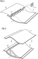
- Figure 2 illustrates a stage during the material layup procedure in a preferred embodiment of the invention.
- a cover sheet 80 of a material such as an elastomer is arranged to line the lower mould 1L so that half of the sheet lies outside the lower mould 1L.
- Fin inserts 11F are then placed into the indentations 10F of the first mould half 1L, which are already lined by the flexible cover sheet 80.
- the lower portion of each fin insert 11F fills an indentation 10F of the lower mould 1L, and the upper portion of the fin insert 11F rests against outer layers of the remainder of the layup 8.
- the cover sheet 80 is then drawn over to cover the entire layup 8.
- the second mould half 1U is then placed over the first mould half 1L in preparation for the VARTM procedure, as shown in Figure 3 .
- the second mould half 1U is detached to reveal the rotor blade.
- the rotor blade 20 incorporates a finned leading-edge protection, with embedded fins 20F extending radially outward from the body of the rotor blade 20.
- the elastomer cover sheet 80 covers the entire moulded part 20.
- FIG 4 shows an alternative embodiment of the inventive method.
- an insert body 12 is provided with fin inserts 11F pre-mounted onto a carrier 12.
- the entire carrier 12 can be placed into the first mould half 1L after arranging a cover sheet 80 (as explained above) into the first mould half to line the mould and the indentations 10F.
- Figure 5 shows a further embodiment of the inventive mould.
- a first mould half 1L is shown to have a cut-out 13X which can receive a mould insert 13, 13'.
- a mould insert 13, 13' is formed with a negative leading-edge profile 10, with indentations 10F as described above, and each mould insert 13, 13' can have a different arrangement of indentations (different indentation sizes, density, etc.); each mould insert 13, 13' has the same basic shape so that it fits into the mould cut-out 13X.
- FIG. 6 shows a wind turbine 2 comprising a number of rotor blades 20 that have been moulded using the inventive method as described above.
- Each rotor blade 20 has a series of fins 20F extending across its leading edge LE.
- One end of a fin 20F extends over the pressure side in the direction of the trailing edge, and the other end of the fin 20F extends over the suction side in the direction of the trailing edge.
- the finned leading-edge profile can have been formed by placing individual fin inserts 11F into the indentations 10F of a mould 1 as described above.
- the finned leading-edge profile can have been formed by placing one or more carrier inserts 12 into the first mould half as described above. In either case, the finned leading-edge profile is formed during the moulding procedure and is therefore an integral part of the rotor blade 20. This embedded finned leading-edge profile is therefore not at risk of detaching from the body of the rotor blade.
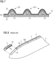
- Figure 7 shows a cross-section through the leading edge of a rotor blade manufactured using the inventive method.
- the drawing shows several embedded fins 20F, formed by arranging fin inserts 11F in the form of twisted rovings into the corresponding indentations of the rotor blade mould halves.
- the fin inserts 11F are arranged to lie against other layers of fibre-reinforced material, for example fibreglass mats 81, which can be arranged in the mould in a layup procedure that will be known to the skilled person.
- the drawing also indicates a cover mat 80 that can be made of a suitably flexible elastomer that stretches over the fin inserts 11F during the VARTM process.
- a protective top-coat 82 can be applied over the entire surface.
- Figure 8 shows a rotor blade 4 augmented in a prior art method in which finned profiles 30 are mounted onto the leading edge of the rotor blade 4 using adhesive 40.
- the profiles 30 have outwardly extending fins 3 that serve to reduce noise and/or to minimize impact damage of the leading edge protection.
- the adhesive 40 may deteriorate over time, so that one or more finned profiles 30 may detach from the rotor blade, leading to maintenance costs and loss of revenue from forced downtime.
- components of a de-icing system can be incorporated during the material layup procedure by arranging one or more heating mats in the leading edge region.
- the heating mats can be thin and flexible and are preferably arranged so that these will lie over the fins in the finished rotor blade.
- the heating mats are deployed to prevent build-up of ice on the leading edge of the rotor blade.
- a heating mat can incorporate electrically conductive elements such as thin copper wires, carbon fibres, etc. as will be known to the skilled person.
Landscapes
- Engineering & Computer Science (AREA)
- Mechanical Engineering (AREA)
- Chemical & Material Sciences (AREA)
- Composite Materials (AREA)
- Sustainable Energy (AREA)
- Life Sciences & Earth Sciences (AREA)
- Sustainable Development (AREA)
- Combustion & Propulsion (AREA)
- General Engineering & Computer Science (AREA)
- Manufacturing & Machinery (AREA)
- Physics & Mathematics (AREA)
- Fluid Mechanics (AREA)
- Wind Motors (AREA)
- Turbine Rotor Nozzle Sealing (AREA)
- Moulds For Moulding Plastics Or The Like (AREA)
Claims (13)
- Procédé de fabrication d'une pale de rotor d'éolienne (20), ledit procédé comprenant les étapes suivantesla préparation d'un moule (1) par- la formation d'un profil de bord d'attaque négatif partiel (10) dans un premier demi-moule (1L), ledit profil de bord d'attaque négatif partiel (10) comprenant une pluralité de premières indentations (10F) le long d'une zone de bord d'attaque (1L_LE) du premier demi-moule (1L),- la formation d'un profil de bord d'attaque négatif partiel (10) dans un deuxième demi-moule (1U), ledit profil de bord d'attaque négatif partiel (10) comprenant une pluralité complémentaire de deuxièmes indentations (10F) le long d'une zone de bord d'attaque (1U_LE) du deuxième demi-moule (1U), et dans lequel la forme combinée d'une première indentation (10F) et d'une deuxième indentation complémentaire (10F) correspond à la forme négative d'une ailette de bord d'attaque (20F) qui s'étendra radialement vers l'extérieur à partir du corps de la pale de rotor (20),le moulage de la pale de rotor (20) par- le dépôt d'un matériau de moulage dans les parties de moule (1L, 1U) et ainsi l'agencement d'inserts d'ailette (11F) dans les indentations (10F) d'un profil de bord d'attaque négatif partiel (10), et- l'exécution d'une procédure de transfert de résine.
- Procédé selon la revendication 1, dans lequel l'étape d'agencement d'inserts d'ailette (11F) dans les indentations (10F) est précédée par une étape de revêtement du premier demi-moule (1L) avec une feuille de protection (80), la superficie de la feuille de protection (80) étant aussi grande que la superficie de la partie (20) à mouler, et dans lequel l'étape d'agencement d'inserts d'ailette (11F) dans les indentations (10F) est suivie par une étape conclusive d'agencement de la feuille de protection (80) sur le matériau déposé dans le premier demi-moule (1L).
- Procédé selon l'une quelconque des revendications précédentes, dans lequel un insert d'ailette (11F) comprend un corps arqué façonné de façon à s'étendre sur le bord d'attaque (LE) de la pale de rotor (20).
- Procédé selon l'une quelconque des revendications précédentes, dans lequel un insert d'ailette (11F) se compose de l'un des éléments suivants : stratifils en fibre de verre, mousse de polyuréthane, mousse de polyéthylène téréphtalate.
- Procédé selon l'une quelconque des revendications précédentes, dans lequel le moulage de la pale de rotor (20) est réalisé par- l'agencement du matériau de moulage dans le premier demi-moule (1L), et- la jointure des parties de moule (1L, 1U) de façon à obtenir un moule fermé (1) avant l'exécution de la procédure de transfert de résine.
- Procédé selon l'une quelconque des revendications précédentes, comprenant une étape de fourniture d'un corps d'insert (12) comprenant une pluralité d'inserts d'ailette (11F) montés sur un support (120) et l'agencement du corps d'insert (12) dans le premier demi-moule (1L) de sorte que les inserts d'ailette (11F) soient reçus par le profil de bord d'attaque négatif partiel (10) du premier demi-moule (1L).
- Pale de rotor d'éolienne (20) fabriquée au moyen du procédé selon la revendication 6 de façon à comprendre une pluralité d'ailettes de bord d'attaque imbriquées (20E) s'étendant sur le bord d'attaque (LE) de la pale de rotor (20) et s'étendant radialement vers l'extérieur à partir du corps de la pale de rotor (20).
- Pale de rotor d'éolienne selon la revendication 7, comprenant un agencement linéaire d'une pluralité de corps d'insert imbriqués (12) portant des inserts d'ailette (11F) de façon à former la pluralité d'ailettes de bord d'attaque (20F).
- Moule (1) destiné à une utilisation dans la fabrication d'une pale de rotor d'éolienne (20), comprenant- un premier demi-moule (1L) façonné de façon à former un côté de la pale de rotor (20), ledit premier demi-moule (1L) comprenant un profil de bord d'attaque négatif partiel (10) comprenant une pluralité de premières indentations (10F) le long d'une zone de bord d'attaque (1L_LE), et- un deuxième demi-moule (1U) façonné de façon à former l'autre côté de la pale de rotor (20), ledit deuxième demi-moule (1U) comprenant un profil de bord d'attaque négatif partiel complémentaire (10) comprenant une pluralité de deuxièmes indentations (10F) le long d'une zone de bord d'attaque (1U_LE), et dans lequel la forme combinée d'une première indentation (10F) et d'une deuxième indentation complémentaire (10F) est la forme négative d'une ailette de bord d'attaque (20F) qui s'étendra radialement vers l'extérieur à partir du corps de la pale de rotor (20).
- Moule selon la revendication précédente, dans lequel le profil de bord d'attaque négatif (10) d'une partie de moule (1L, 1U) est formé sous la forme d'un insert de moule (13), et dans lequel une partie de moule (1L, 1U) est formée de façon à comprendre une découpe complémentaire (13X) façonnée de façon à recevoir l'insert de moule (13).
- Ensemble moule (1, 13) comprenant- un moule (1) selon la revendication 10 destiné à une utilisation dans la fabrication d'un nombre de pales de rotor d'éolienne (20), et- une pluralité d'inserts de moule (13), dans lequel les inserts de moule (13) sont formés de façon à présenter des profils de bord d'attaque négatifs différents (10).
- Ensemble moule selon la revendication précédente, dans lequel les dimensions d'un profil de bord d'attaque négatif (10) d'un insert de moule (13) sont choisies en fonction de conditions météorologiques au niveau d'un site d'installation d'éoliennes prévu.
- Ensemble moule selon la revendication 11 ou 12, dans lequel les parties de moule (1L, 1U) comprennent un moyen de raccordement destiné à faciliter le raccordement du deuxième demi-moule (1U) au premier demi-moule (1L) avant une procédure de transfert de résine.
Priority Applications (6)
| Application Number | Priority Date | Filing Date | Title |
|---|---|---|---|
| PT201738432T PT3910193T (pt) | 2020-05-11 | 2020-05-11 | Método de fabrico de uma pá de rotor de turbina eólica |
| DK20173843.2T DK3910193T3 (da) | 2020-05-11 | 2020-05-11 | Fremgangsmåde til fremstilling af et vindmølle-rotorblad |
| EP20173843.2A EP3910193B1 (fr) | 2020-05-11 | 2020-05-11 | Procédés de fabrication de pale de rotor d'éolienne |
| ES20173843T ES2980372T3 (es) | 2020-05-11 | 2020-05-11 | Método de fabricación de una pala de rotor de turbina eólica |
| US17/314,287 US11773824B2 (en) | 2020-05-11 | 2021-05-07 | Method of manufacturing a wind turbine rotor blade |
| CN202110512274.9A CN113635587B (zh) | 2020-05-11 | 2021-05-11 | 制造风力涡轮机转子叶片的方法 |
Applications Claiming Priority (1)
| Application Number | Priority Date | Filing Date | Title |
|---|---|---|---|
| EP20173843.2A EP3910193B1 (fr) | 2020-05-11 | 2020-05-11 | Procédés de fabrication de pale de rotor d'éolienne |
Publications (2)
| Publication Number | Publication Date |
|---|---|
| EP3910193A1 EP3910193A1 (fr) | 2021-11-17 |
| EP3910193B1 true EP3910193B1 (fr) | 2024-03-20 |
Family
ID=70680362
Family Applications (1)
| Application Number | Title | Priority Date | Filing Date |
|---|---|---|---|
| EP20173843.2A Active EP3910193B1 (fr) | 2020-05-11 | 2020-05-11 | Procédés de fabrication de pale de rotor d'éolienne |
Country Status (6)
| Country | Link |
|---|---|
| US (1) | US11773824B2 (fr) |
| EP (1) | EP3910193B1 (fr) |
| CN (1) | CN113635587B (fr) |
| DK (1) | DK3910193T3 (fr) |
| ES (1) | ES2980372T3 (fr) |
| PT (1) | PT3910193T (fr) |
Families Citing this family (5)
| Publication number | Priority date | Publication date | Assignee | Title |
|---|---|---|---|---|
| EP3724486B1 (fr) * | 2017-12-12 | 2023-05-31 | LM Wind Power A/S | Dispositif de bord d'attaque de pale d'eolienne et procédé d'installation du dispositif de bord d'attaque |
| EP4291770A1 (fr) * | 2021-02-12 | 2023-12-20 | LM Wind Power A/S | Protection de bord d'attaque à impact de bruit réduit |
| CN116811290B (zh) * | 2023-08-28 | 2023-11-10 | 太原理工大学 | 一种ⅴ型全复合材料压力容器成型装置及方法 |
| FR3159764A1 (fr) * | 2024-02-29 | 2025-09-05 | Safran Aircraft Engines | Procédé de formage et d’assemblage par drapage d’une pièce 2D sur une pièce 3D |
| FR3161461B1 (fr) * | 2024-04-23 | 2026-04-03 | Safran | Procede de fabrication d’une aube pour une turbomachine d’aeronef |
Family Cites Families (21)
| Publication number | Priority date | Publication date | Assignee | Title |
|---|---|---|---|---|
| WO2000015961A1 (fr) * | 1998-09-16 | 2000-03-23 | Lm Glasfiber A/S | Pale de turbine munie de generateurs de tourbillons |
| PT1805412E (pt) | 2004-10-18 | 2016-06-08 | Whalepower Corp | Turbina e compressor empregando uma conceção de rotor com bordo de ataque de tubérculos |
| CN101484692B (zh) * | 2006-06-09 | 2011-08-31 | 维斯塔斯风力系统有限公司 | 风轮机叶片和桨距控制式风轮机 |
| DK2106900T3 (da) * | 2008-04-03 | 2012-07-09 | Siemens Ag | Form og fremgangsmåde til vakuumunderstøttet resinoverføringsstøbning |
| US9039381B2 (en) * | 2010-12-17 | 2015-05-26 | Vestas Wind Systems A/S | Wind turbine blade and method for manufacturing a wind turbine blade with vortex generators |
| EP2736805B1 (fr) * | 2011-07-22 | 2017-06-14 | LM WP Patent Holding A/S | Pale de turbine éolienne comprenant des générateurs de tourbillons |
| JP6189088B2 (ja) * | 2013-05-28 | 2017-08-30 | テラル株式会社 | ロータ |
| WO2015003718A1 (fr) * | 2013-07-11 | 2015-01-15 | Vestas Wind Systems A/S | Ensemble pale de turbine éolienne muni d'un atténuateur de bruit sur la pointe de pale |
| WO2016019468A1 (fr) * | 2014-08-05 | 2016-02-11 | Ryan Church | Structure comportant des parties saillantes rigides, adaptée pour traverser un environnement fluide |
| EP3194136A4 (fr) * | 2014-09-15 | 2018-04-18 | Envision Energy (Denmark) ApS | Pale d'éolienne à longueur de membrure personnalisée |
| EP3037655A1 (fr) * | 2014-12-22 | 2016-06-29 | Siemens Aktiengesellschaft | Extension de pale de rotor |
| CN205478093U (zh) * | 2016-01-18 | 2016-08-17 | 中节能港建(甘肃)风力发电有限公司 | 一种涡流发生器及安装涡流发生器的风电叶片 |
| JP2020507712A (ja) * | 2017-02-17 | 2020-03-12 | エムエイチアイ ヴェスタス オフショア ウィンド エー/エス | 風力タービンブレードの前縁部保護 |
| DE102017107464A1 (de) * | 2017-04-06 | 2018-10-11 | Teg Tubercle Engineering Group Gmbh | Nachrüstkörper für ein Rotorblatt einer Windkraftanlage, nachgerüstetes Rotorblatt und Verfahren zum Nachrüsten des Rotorblatts |
| EP3631196B1 (fr) * | 2017-05-22 | 2025-10-01 | LM Wind Power A/S | Pale d'éolienne et procédé |
| WO2019015731A1 (fr) * | 2017-07-20 | 2019-01-24 | Vestas Wind Systems A/S | Pale d'éolienne |
| US10640197B1 (en) * | 2017-10-31 | 2020-05-05 | Wisk Aero Llc | Composite airfoil with rolled fiberglass reinforced leading edge |
| EP3724486B1 (fr) * | 2017-12-12 | 2023-05-31 | LM Wind Power A/S | Dispositif de bord d'attaque de pale d'eolienne et procédé d'installation du dispositif de bord d'attaque |
| ES2954182T3 (es) * | 2018-03-08 | 2023-11-20 | Siemens Gamesa Renewable Energy As | Cubierta protectora para proteger un borde de ataque de una pala de turbina eólica |
| CN110206680A (zh) * | 2019-06-05 | 2019-09-06 | 上海电气风电集团有限公司 | 一种涡流发生器、风机叶片及其制造方法 |
| EP3822478A1 (fr) * | 2019-11-15 | 2021-05-19 | Siemens Gamesa Renewable Energy A/S | Procédé de fabrication d'une coque d'une pale d'éolienne ayant une meilleure protection contre l'érosion du bord d'attaque, procédé de fabrication de la pale d'éolienne, coque, pale d'éolienne et éolienne |
-
2020
- 2020-05-11 EP EP20173843.2A patent/EP3910193B1/fr active Active
- 2020-05-11 PT PT201738432T patent/PT3910193T/pt unknown
- 2020-05-11 ES ES20173843T patent/ES2980372T3/es active Active
- 2020-05-11 DK DK20173843.2T patent/DK3910193T3/da active
-
2021
- 2021-05-07 US US17/314,287 patent/US11773824B2/en active Active
- 2021-05-11 CN CN202110512274.9A patent/CN113635587B/zh active Active
Also Published As
| Publication number | Publication date |
|---|---|
| CN113635587A (zh) | 2021-11-12 |
| DK3910193T3 (da) | 2024-05-06 |
| ES2980372T3 (es) | 2024-10-01 |
| CN113635587B (zh) | 2023-09-29 |
| EP3910193A1 (fr) | 2021-11-17 |
| US11773824B2 (en) | 2023-10-03 |
| US20210348594A1 (en) | 2021-11-11 |
| PT3910193T (pt) | 2024-05-28 |
Similar Documents
| Publication | Publication Date | Title |
|---|---|---|
| EP3910193B1 (fr) | Procédés de fabrication de pale de rotor d'éolienne | |
| CN102996327B (zh) | 风机的转子叶片及相应制造方法 | |
| CA2992633C (fr) | Pale d'eolienne ayant un bouclier anti-erosion | |
| US11629689B2 (en) | Polyurethane material, process for preparing such material and protective cover for wind turbine blade | |
| US8896980B2 (en) | Wind turbine blade with an integrated lightning conductor | |
| US20210180562A1 (en) | A leading edge device, methods of manufacturing and installing the leading edge device and a wind turbine blade | |
| US9677538B2 (en) | Wind turbine rotor blade assembly with root extension panel and method of assembly | |
| US20110182741A1 (en) | Composite fan blade leading edge recamber | |
| EP3436256B1 (fr) | Ensemble moule d'extrémité de pale de rotor comprenant des vessies dilatables et procédé de formation d'extrémité de pale de rotor | |
| US11719220B2 (en) | Method of manufacturing a wind turbine blade and a wind turbine blade thereof | |
| JP2023546459A (ja) | 前縁部材を備える風力タービンロータブレード | |
| WO2016189278A1 (fr) | Blindage de bord d'attaque | |
| EP3400133B1 (fr) | Procédé de moulage d'une partie de coque de pale d'éolienne | |
| EP3436252B1 (fr) | Ensemble moule d'extrémité de pale de rotor comprenant un noyau solide et procédé de formation d'extrémité de pale de rotor | |
| US20210148328A1 (en) | Method of manufacturing a shell of a wind turbine blade having improved leading edge erosion protection, method for manufacturing the wind turbine blade, shell, wind turbine blade and wind turbine | |
| EP4212321A1 (fr) | Fabrication d'un élément d'incorporation d'une pale de turbine éolienne |
Legal Events
| Date | Code | Title | Description |
|---|---|---|---|
| PUAI | Public reference made under article 153(3) epc to a published international application that has entered the european phase |
Free format text: ORIGINAL CODE: 0009012 |
|
| STAA | Information on the status of an ep patent application or granted ep patent |
Free format text: STATUS: THE APPLICATION HAS BEEN PUBLISHED |
|
| AK | Designated contracting states |
Kind code of ref document: A1 Designated state(s): AL AT BE BG CH CY CZ DE DK EE ES FI FR GB GR HR HU IE IS IT LI LT LU LV MC MK MT NL NO PL PT RO RS SE SI SK SM TR |
|
| B565 | Issuance of search results under rule 164(2) epc |
Effective date: 20201026 |
|
| STAA | Information on the status of an ep patent application or granted ep patent |
Free format text: STATUS: REQUEST FOR EXAMINATION WAS MADE |
|
| 17P | Request for examination filed |
Effective date: 20220517 |
|
| RBV | Designated contracting states (corrected) |
Designated state(s): AL AT BE BG CH CY CZ DE DK EE ES FI FR GB GR HR HU IE IS IT LI LT LU LV MC MK MT NL NO PL PT RO RS SE SI SK SM TR |
|
| GRAP | Despatch of communication of intention to grant a patent |
Free format text: ORIGINAL CODE: EPIDOSNIGR1 |
|
| STAA | Information on the status of an ep patent application or granted ep patent |
Free format text: STATUS: GRANT OF PATENT IS INTENDED |
|
| RIC1 | Information provided on ipc code assigned before grant |
Ipc: B29C 33/30 20060101ALI20231009BHEP Ipc: B29L 31/08 20060101ALI20231009BHEP Ipc: B29D 99/00 20100101ALI20231009BHEP Ipc: B29C 70/70 20060101ALI20231009BHEP Ipc: B29C 70/30 20060101ALI20231009BHEP Ipc: B29C 70/48 20060101ALI20231009BHEP Ipc: F03D 1/06 20060101AFI20231009BHEP |
|
| INTG | Intention to grant announced |
Effective date: 20231025 |
|
| GRAS | Grant fee paid |
Free format text: ORIGINAL CODE: EPIDOSNIGR3 |
|
| GRAA | (expected) grant |
Free format text: ORIGINAL CODE: 0009210 |
|
| STAA | Information on the status of an ep patent application or granted ep patent |
Free format text: STATUS: THE PATENT HAS BEEN GRANTED |
|
| AK | Designated contracting states |
Kind code of ref document: B1 Designated state(s): AL AT BE BG CH CY CZ DE DK EE ES FI FR GB GR HR HU IE IS IT LI LT LU LV MC MK MT NL NO PL PT RO RS SE SI SK SM TR |
|
| REG | Reference to a national code |
Ref country code: GB Ref legal event code: FG4D |
|
| REG | Reference to a national code |
Ref country code: CH Ref legal event code: EP |
|
| REG | Reference to a national code |
Ref country code: DE Ref legal event code: R096 Ref document number: 602020027398 Country of ref document: DE |
|
| REG | Reference to a national code |
Ref country code: IE Ref legal event code: FG4D |
|
| REG | Reference to a national code |
Ref country code: DK Ref legal event code: T3 Effective date: 20240502 |
|
| REG | Reference to a national code |
Ref country code: PT Ref legal event code: SC4A Ref document number: 3910193 Country of ref document: PT Date of ref document: 20240528 Kind code of ref document: T Free format text: AVAILABILITY OF NATIONAL TRANSLATION Effective date: 20240521 |
|
| PG25 | Lapsed in a contracting state [announced via postgrant information from national office to epo] |
Ref country code: LT Free format text: LAPSE BECAUSE OF FAILURE TO SUBMIT A TRANSLATION OF THE DESCRIPTION OR TO PAY THE FEE WITHIN THE PRESCRIBED TIME-LIMIT Effective date: 20240320 |
|
| REG | Reference to a national code |
Ref country code: LT Ref legal event code: MG9D |
|
| PG25 | Lapsed in a contracting state [announced via postgrant information from national office to epo] |
Ref country code: GR Free format text: LAPSE BECAUSE OF FAILURE TO SUBMIT A TRANSLATION OF THE DESCRIPTION OR TO PAY THE FEE WITHIN THE PRESCRIBED TIME-LIMIT Effective date: 20240621 |
|
| PG25 | Lapsed in a contracting state [announced via postgrant information from national office to epo] |
Ref country code: RS Free format text: LAPSE BECAUSE OF FAILURE TO SUBMIT A TRANSLATION OF THE DESCRIPTION OR TO PAY THE FEE WITHIN THE PRESCRIBED TIME-LIMIT Effective date: 20240620 Ref country code: HR Free format text: LAPSE BECAUSE OF FAILURE TO SUBMIT A TRANSLATION OF THE DESCRIPTION OR TO PAY THE FEE WITHIN THE PRESCRIBED TIME-LIMIT Effective date: 20240320 |
|
| REG | Reference to a national code |
Ref country code: NL Ref legal event code: MP Effective date: 20240320 |
|
| PG25 | Lapsed in a contracting state [announced via postgrant information from national office to epo] |
Ref country code: RS Free format text: LAPSE BECAUSE OF FAILURE TO SUBMIT A TRANSLATION OF THE DESCRIPTION OR TO PAY THE FEE WITHIN THE PRESCRIBED TIME-LIMIT Effective date: 20240620 Ref country code: NO Free format text: LAPSE BECAUSE OF FAILURE TO SUBMIT A TRANSLATION OF THE DESCRIPTION OR TO PAY THE FEE WITHIN THE PRESCRIBED TIME-LIMIT Effective date: 20240620 Ref country code: LT Free format text: LAPSE BECAUSE OF FAILURE TO SUBMIT A TRANSLATION OF THE DESCRIPTION OR TO PAY THE FEE WITHIN THE PRESCRIBED TIME-LIMIT Effective date: 20240320 Ref country code: HR Free format text: LAPSE BECAUSE OF FAILURE TO SUBMIT A TRANSLATION OF THE DESCRIPTION OR TO PAY THE FEE WITHIN THE PRESCRIBED TIME-LIMIT Effective date: 20240320 Ref country code: GR Free format text: LAPSE BECAUSE OF FAILURE TO SUBMIT A TRANSLATION OF THE DESCRIPTION OR TO PAY THE FEE WITHIN THE PRESCRIBED TIME-LIMIT Effective date: 20240621 Ref country code: FI Free format text: LAPSE BECAUSE OF FAILURE TO SUBMIT A TRANSLATION OF THE DESCRIPTION OR TO PAY THE FEE WITHIN THE PRESCRIBED TIME-LIMIT Effective date: 20240320 Ref country code: BG Free format text: LAPSE BECAUSE OF FAILURE TO SUBMIT A TRANSLATION OF THE DESCRIPTION OR TO PAY THE FEE WITHIN THE PRESCRIBED TIME-LIMIT Effective date: 20240320 |
|
| REG | Reference to a national code |
Ref country code: AT Ref legal event code: MK05 Ref document number: 1668026 Country of ref document: AT Kind code of ref document: T Effective date: 20240320 |
|
| PG25 | Lapsed in a contracting state [announced via postgrant information from national office to epo] |
Ref country code: SE Free format text: LAPSE BECAUSE OF FAILURE TO SUBMIT A TRANSLATION OF THE DESCRIPTION OR TO PAY THE FEE WITHIN THE PRESCRIBED TIME-LIMIT Effective date: 20240320 Ref country code: LV Free format text: LAPSE BECAUSE OF FAILURE TO SUBMIT A TRANSLATION OF THE DESCRIPTION OR TO PAY THE FEE WITHIN THE PRESCRIBED TIME-LIMIT Effective date: 20240320 |
|
| PG25 | Lapsed in a contracting state [announced via postgrant information from national office to epo] |
Ref country code: NL Free format text: LAPSE BECAUSE OF FAILURE TO SUBMIT A TRANSLATION OF THE DESCRIPTION OR TO PAY THE FEE WITHIN THE PRESCRIBED TIME-LIMIT Effective date: 20240320 |
|
| PG25 | Lapsed in a contracting state [announced via postgrant information from national office to epo] |
Ref country code: NL Free format text: LAPSE BECAUSE OF FAILURE TO SUBMIT A TRANSLATION OF THE DESCRIPTION OR TO PAY THE FEE WITHIN THE PRESCRIBED TIME-LIMIT Effective date: 20240320 |
|
| REG | Reference to a national code |
Ref country code: ES Ref legal event code: FG2A Ref document number: 2980372 Country of ref document: ES Kind code of ref document: T3 Effective date: 20241001 |
|
| PG25 | Lapsed in a contracting state [announced via postgrant information from national office to epo] |
Ref country code: IS Free format text: LAPSE BECAUSE OF FAILURE TO SUBMIT A TRANSLATION OF THE DESCRIPTION OR TO PAY THE FEE WITHIN THE PRESCRIBED TIME-LIMIT Effective date: 20240720 |
|
| PG25 | Lapsed in a contracting state [announced via postgrant information from national office to epo] |
Ref country code: SM Free format text: LAPSE BECAUSE OF FAILURE TO SUBMIT A TRANSLATION OF THE DESCRIPTION OR TO PAY THE FEE WITHIN THE PRESCRIBED TIME-LIMIT Effective date: 20240320 |
|
| PG25 | Lapsed in a contracting state [announced via postgrant information from national office to epo] |
Ref country code: EE Free format text: LAPSE BECAUSE OF FAILURE TO SUBMIT A TRANSLATION OF THE DESCRIPTION OR TO PAY THE FEE WITHIN THE PRESCRIBED TIME-LIMIT Effective date: 20240320 Ref country code: CZ Free format text: LAPSE BECAUSE OF FAILURE TO SUBMIT A TRANSLATION OF THE DESCRIPTION OR TO PAY THE FEE WITHIN THE PRESCRIBED TIME-LIMIT Effective date: 20240320 |
|
| PG25 | Lapsed in a contracting state [announced via postgrant information from national office to epo] |
Ref country code: AT Free format text: LAPSE BECAUSE OF FAILURE TO SUBMIT A TRANSLATION OF THE DESCRIPTION OR TO PAY THE FEE WITHIN THE PRESCRIBED TIME-LIMIT Effective date: 20240320 |
|
| PG25 | Lapsed in a contracting state [announced via postgrant information from national office to epo] |
Ref country code: PL Free format text: LAPSE BECAUSE OF FAILURE TO SUBMIT A TRANSLATION OF THE DESCRIPTION OR TO PAY THE FEE WITHIN THE PRESCRIBED TIME-LIMIT Effective date: 20240320 |
|
| PG25 | Lapsed in a contracting state [announced via postgrant information from national office to epo] |
Ref country code: SK Free format text: LAPSE BECAUSE OF FAILURE TO SUBMIT A TRANSLATION OF THE DESCRIPTION OR TO PAY THE FEE WITHIN THE PRESCRIBED TIME-LIMIT Effective date: 20240320 |
|
| PG25 | Lapsed in a contracting state [announced via postgrant information from national office to epo] |
Ref country code: SM Free format text: LAPSE BECAUSE OF FAILURE TO SUBMIT A TRANSLATION OF THE DESCRIPTION OR TO PAY THE FEE WITHIN THE PRESCRIBED TIME-LIMIT Effective date: 20240320 Ref country code: SK Free format text: LAPSE BECAUSE OF FAILURE TO SUBMIT A TRANSLATION OF THE DESCRIPTION OR TO PAY THE FEE WITHIN THE PRESCRIBED TIME-LIMIT Effective date: 20240320 Ref country code: RO Free format text: LAPSE BECAUSE OF FAILURE TO SUBMIT A TRANSLATION OF THE DESCRIPTION OR TO PAY THE FEE WITHIN THE PRESCRIBED TIME-LIMIT Effective date: 20240320 Ref country code: PL Free format text: LAPSE BECAUSE OF FAILURE TO SUBMIT A TRANSLATION OF THE DESCRIPTION OR TO PAY THE FEE WITHIN THE PRESCRIBED TIME-LIMIT Effective date: 20240320 Ref country code: IS Free format text: LAPSE BECAUSE OF FAILURE TO SUBMIT A TRANSLATION OF THE DESCRIPTION OR TO PAY THE FEE WITHIN THE PRESCRIBED TIME-LIMIT Effective date: 20240720 Ref country code: EE Free format text: LAPSE BECAUSE OF FAILURE TO SUBMIT A TRANSLATION OF THE DESCRIPTION OR TO PAY THE FEE WITHIN THE PRESCRIBED TIME-LIMIT Effective date: 20240320 Ref country code: CZ Free format text: LAPSE BECAUSE OF FAILURE TO SUBMIT A TRANSLATION OF THE DESCRIPTION OR TO PAY THE FEE WITHIN THE PRESCRIBED TIME-LIMIT Effective date: 20240320 Ref country code: AT Free format text: LAPSE BECAUSE OF FAILURE TO SUBMIT A TRANSLATION OF THE DESCRIPTION OR TO PAY THE FEE WITHIN THE PRESCRIBED TIME-LIMIT Effective date: 20240320 |
|
| PG25 | Lapsed in a contracting state [announced via postgrant information from national office to epo] |
Ref country code: IT Free format text: LAPSE BECAUSE OF FAILURE TO SUBMIT A TRANSLATION OF THE DESCRIPTION OR TO PAY THE FEE WITHIN THE PRESCRIBED TIME-LIMIT Effective date: 20240320 |
|
| REG | Reference to a national code |
Ref country code: DE Ref legal event code: R097 Ref document number: 602020027398 Country of ref document: DE |
|
| REG | Reference to a national code |
Ref country code: CH Ref legal event code: PL |
|
| PG25 | Lapsed in a contracting state [announced via postgrant information from national office to epo] |
Ref country code: IT Free format text: LAPSE BECAUSE OF FAILURE TO SUBMIT A TRANSLATION OF THE DESCRIPTION OR TO PAY THE FEE WITHIN THE PRESCRIBED TIME-LIMIT Effective date: 20240320 |
|
| PG25 | Lapsed in a contracting state [announced via postgrant information from national office to epo] |
Ref country code: MC Free format text: LAPSE BECAUSE OF FAILURE TO SUBMIT A TRANSLATION OF THE DESCRIPTION OR TO PAY THE FEE WITHIN THE PRESCRIBED TIME-LIMIT Effective date: 20240320 |
|
| PG25 | Lapsed in a contracting state [announced via postgrant information from national office to epo] |
Ref country code: LU Free format text: LAPSE BECAUSE OF NON-PAYMENT OF DUE FEES Effective date: 20240511 |
|
| PLBE | No opposition filed within time limit |
Free format text: ORIGINAL CODE: 0009261 |
|
| STAA | Information on the status of an ep patent application or granted ep patent |
Free format text: STATUS: NO OPPOSITION FILED WITHIN TIME LIMIT |
|
| PG25 | Lapsed in a contracting state [announced via postgrant information from national office to epo] |
Ref country code: MC Free format text: LAPSE BECAUSE OF FAILURE TO SUBMIT A TRANSLATION OF THE DESCRIPTION OR TO PAY THE FEE WITHIN THE PRESCRIBED TIME-LIMIT Effective date: 20240320 Ref country code: LU Free format text: LAPSE BECAUSE OF NON-PAYMENT OF DUE FEES Effective date: 20240511 Ref country code: CH Free format text: LAPSE BECAUSE OF NON-PAYMENT OF DUE FEES Effective date: 20240531 |
|
| REG | Reference to a national code |
Ref country code: BE Ref legal event code: MM Effective date: 20240531 |
|
| 26N | No opposition filed |
Effective date: 20241223 |
|
| PG25 | Lapsed in a contracting state [announced via postgrant information from national office to epo] |
Ref country code: IE Free format text: LAPSE BECAUSE OF NON-PAYMENT OF DUE FEES Effective date: 20240511 |
|
| PG25 | Lapsed in a contracting state [announced via postgrant information from national office to epo] |
Ref country code: SI Free format text: LAPSE BECAUSE OF FAILURE TO SUBMIT A TRANSLATION OF THE DESCRIPTION OR TO PAY THE FEE WITHIN THE PRESCRIBED TIME-LIMIT Effective date: 20240320 Ref country code: BE Free format text: LAPSE BECAUSE OF NON-PAYMENT OF DUE FEES Effective date: 20240531 |
|
| PGFP | Annual fee paid to national office [announced via postgrant information from national office to epo] |
Ref country code: DE Payment date: 20250528 Year of fee payment: 6 |
|
| PGFP | Annual fee paid to national office [announced via postgrant information from national office to epo] |
Ref country code: GB Payment date: 20250520 Year of fee payment: 6 Ref country code: ES Payment date: 20250612 Year of fee payment: 6 Ref country code: DK Payment date: 20250526 Year of fee payment: 6 |
|
| PGFP | Annual fee paid to national office [announced via postgrant information from national office to epo] |
Ref country code: PT Payment date: 20250414 Year of fee payment: 6 |
|
| PGFP | Annual fee paid to national office [announced via postgrant information from national office to epo] |
Ref country code: FR Payment date: 20250526 Year of fee payment: 6 |
|
| PG25 | Lapsed in a contracting state [announced via postgrant information from national office to epo] |
Ref country code: CY Free format text: LAPSE BECAUSE OF FAILURE TO SUBMIT A TRANSLATION OF THE DESCRIPTION OR TO PAY THE FEE WITHIN THE PRESCRIBED TIME-LIMIT; INVALID AB INITIO Effective date: 20200511 |
|
| PG25 | Lapsed in a contracting state [announced via postgrant information from national office to epo] |
Ref country code: HU Free format text: LAPSE BECAUSE OF FAILURE TO SUBMIT A TRANSLATION OF THE DESCRIPTION OR TO PAY THE FEE WITHIN THE PRESCRIBED TIME-LIMIT; INVALID AB INITIO Effective date: 20200511 |