EP3910206A1 - Palier lisse, agencement de palier lisse, boîte de vitesses et chaine cinématique pour éoliennes - Google Patents
Palier lisse, agencement de palier lisse, boîte de vitesses et chaine cinématique pour éoliennes Download PDFInfo
- Publication number
- EP3910206A1 EP3910206A1 EP20174148.5A EP20174148A EP3910206A1 EP 3910206 A1 EP3910206 A1 EP 3910206A1 EP 20174148 A EP20174148 A EP 20174148A EP 3910206 A1 EP3910206 A1 EP 3910206A1
- Authority
- EP
- European Patent Office
- Prior art keywords
- bearing
- sliding
- bearing component
- slide
- alloy
- Prior art date
- Legal status (The legal status is an assumption and is not a legal conclusion. Google has not performed a legal analysis and makes no representation as to the accuracy of the status listed.)
- Withdrawn
Links
- 230000005540 biological transmission Effects 0.000 title claims abstract description 26
- 239000000463 material Substances 0.000 claims abstract description 48
- 238000000576 coating method Methods 0.000 claims abstract description 47
- 239000011248 coating agent Substances 0.000 claims abstract description 45
- 239000000314 lubricant Substances 0.000 claims abstract description 20
- 229910045601 alloy Inorganic materials 0.000 claims description 24
- 239000000956 alloy Substances 0.000 claims description 24
- -1 polytetrafluoroethylene Polymers 0.000 claims description 18
- 229920000090 poly(aryl ether) Polymers 0.000 claims description 9
- 239000012948 isocyanate Substances 0.000 claims description 8
- 150000002513 isocyanates Chemical group 0.000 claims description 8
- 238000004590 computer program Methods 0.000 claims description 7
- RTZKZFJDLAIYFH-UHFFFAOYSA-N Diethyl ether Chemical compound CCOCC RTZKZFJDLAIYFH-UHFFFAOYSA-N 0.000 claims description 6
- 229910000831 Steel Inorganic materials 0.000 claims description 6
- UCKMPCXJQFINFW-UHFFFAOYSA-N Sulphide Chemical compound [S-2] UCKMPCXJQFINFW-UHFFFAOYSA-N 0.000 claims description 6
- 239000003822 epoxy resin Chemical class 0.000 claims description 6
- 229920003055 poly(ester-imide) Polymers 0.000 claims description 6
- 229920000647 polyepoxide Chemical class 0.000 claims description 6
- 229920001343 polytetrafluoroethylene Polymers 0.000 claims description 6
- 239000004810 polytetrafluoroethylene Substances 0.000 claims description 6
- 238000007767 slide coating Methods 0.000 claims description 6
- 239000010959 steel Substances 0.000 claims description 6
- 125000003118 aryl group Chemical group 0.000 claims description 5
- LNEPOXFFQSENCJ-UHFFFAOYSA-N haloperidol Chemical class C1CC(O)(C=2C=CC(Cl)=CC=2)CCN1CCCC(=O)C1=CC=C(F)C=C1 LNEPOXFFQSENCJ-UHFFFAOYSA-N 0.000 claims description 5
- 229910001018 Cast iron Inorganic materials 0.000 claims description 4
- 229910001208 Crucible steel Inorganic materials 0.000 claims description 4
- 239000004696 Poly ether ether ketone Substances 0.000 claims description 4
- 229920002530 polyetherether ketone Polymers 0.000 claims description 4
- 238000005507 spraying Methods 0.000 claims description 4
- 229910001316 Ag alloy Inorganic materials 0.000 claims description 3
- 229910016943 AlZn Inorganic materials 0.000 claims description 3
- 229910000789 Aluminium-silicon alloy Inorganic materials 0.000 claims description 3
- 229910001152 Bi alloy Inorganic materials 0.000 claims description 3
- 229910001369 Brass Inorganic materials 0.000 claims description 3
- 229910000906 Bronze Inorganic materials 0.000 claims description 3
- 229910018565 CuAl Inorganic materials 0.000 claims description 3
- 229910002535 CuZn Inorganic materials 0.000 claims description 3
- 239000004812 Fluorinated ethylene propylene Substances 0.000 claims description 3
- 229920002302 Nylon 6,6 Polymers 0.000 claims description 3
- 229930040373 Paraformaldehyde Natural products 0.000 claims description 3
- 229920001774 Perfluoroether Polymers 0.000 claims description 3
- 239000004962 Polyamide-imide Substances 0.000 claims description 3
- 239000004695 Polyether sulfone Substances 0.000 claims description 3
- 239000004734 Polyphenylene sulfide Substances 0.000 claims description 3
- 229910001361 White metal Inorganic materials 0.000 claims description 3
- 239000010951 brass Substances 0.000 claims description 3
- 239000010974 bronze Substances 0.000 claims description 3
- 239000000919 ceramic Substances 0.000 claims description 3
- 229920001577 copolymer Polymers 0.000 claims description 3
- KUNSUQLRTQLHQQ-UHFFFAOYSA-N copper tin Chemical compound [Cu].[Sn] KUNSUQLRTQLHQQ-UHFFFAOYSA-N 0.000 claims description 3
- QHSJIZLJUFMIFP-UHFFFAOYSA-N ethene;1,1,2,2-tetrafluoroethene Chemical group C=C.FC(F)=C(F)F QHSJIZLJUFMIFP-UHFFFAOYSA-N 0.000 claims description 3
- 229920000840 ethylene tetrafluoroethylene copolymer Polymers 0.000 claims description 3
- 150000002576 ketones Chemical class 0.000 claims description 3
- 229920009441 perflouroethylene propylene Polymers 0.000 claims description 3
- 229920003192 poly(bis maleimide) Polymers 0.000 claims description 3
- 229920002493 poly(chlorotrifluoroethylene) Polymers 0.000 claims description 3
- 229920002492 poly(sulfone) Polymers 0.000 claims description 3
- 229920002312 polyamide-imide Polymers 0.000 claims description 3
- 229920006260 polyaryletherketone Polymers 0.000 claims description 3
- 239000005023 polychlorotrifluoroethylene (PCTFE) polymer Substances 0.000 claims description 3
- 229920006393 polyether sulfone Polymers 0.000 claims description 3
- 229920001601 polyetherimide Chemical group 0.000 claims description 3
- 229920006324 polyoxymethylene Polymers 0.000 claims description 3
- 229920000069 polyphenylene sulfide Polymers 0.000 claims description 3
- 229920001296 polysiloxane Polymers 0.000 claims description 3
- 229920002981 polyvinylidene fluoride Polymers 0.000 claims description 3
- XIUFWXXRTPHHDQ-UHFFFAOYSA-N prop-1-ene;1,1,2,2-tetrafluoroethene Chemical group CC=C.FC(F)=C(F)F XIUFWXXRTPHHDQ-UHFFFAOYSA-N 0.000 claims description 3
- 239000010969 white metal Substances 0.000 claims description 3
- 229920002292 Nylon 6 Polymers 0.000 claims description 2
- 239000002033 PVDF binder Substances 0.000 claims description 2
- 229920005603 alternating copolymer Polymers 0.000 claims description 2
- 238000007667 floating Methods 0.000 claims description 2
- 150000003949 imides Chemical class 0.000 claims description 2
- 238000007654 immersion Methods 0.000 claims description 2
- 229920002620 polyvinyl fluoride Polymers 0.000 claims description 2
- 239000000126 substance Substances 0.000 claims description 2
- 229920002554 vinyl polymer Polymers 0.000 claims description 2
- 238000000926 separation method Methods 0.000 claims 2
- XQUPVDVFXZDTLT-UHFFFAOYSA-N 1-[4-[[4-(2,5-dioxopyrrol-1-yl)phenyl]methyl]phenyl]pyrrole-2,5-dione Chemical compound O=C1C=CC(=O)N1C(C=C1)=CC=C1CC1=CC=C(N2C(C=CC2=O)=O)C=C1 XQUPVDVFXZDTLT-UHFFFAOYSA-N 0.000 claims 1
- 150000002148 esters Chemical class 0.000 claims 1
- 229920001568 phenolic resin Polymers 0.000 claims 1
- 239000005011 phenolic resin Substances 0.000 claims 1
- 229920005604 random copolymer Polymers 0.000 claims 1
- 238000004519 manufacturing process Methods 0.000 description 8
- 239000010410 layer Substances 0.000 description 7
- 229920001721 polyimide Polymers 0.000 description 6
- 239000009719 polyimide resin Substances 0.000 description 6
- 230000003746 surface roughness Effects 0.000 description 6
- 238000006243 chemical reaction Methods 0.000 description 3
- 230000008439 repair process Effects 0.000 description 3
- 239000004698 Polyethylene Substances 0.000 description 2
- 239000004568 cement Substances 0.000 description 2
- 238000002485 combustion reaction Methods 0.000 description 2
- 230000008021 deposition Effects 0.000 description 2
- 230000007246 mechanism Effects 0.000 description 2
- 229920001643 poly(ether ketone) Polymers 0.000 description 2
- 229920000573 polyethylene Polymers 0.000 description 2
- 239000011435 rock Substances 0.000 description 2
- 239000012791 sliding layer Substances 0.000 description 2
- 230000002269 spontaneous effect Effects 0.000 description 2
- 229910000897 Babbitt (metal) Inorganic materials 0.000 description 1
- 230000004888 barrier function Effects 0.000 description 1
- 230000000295 complement effect Effects 0.000 description 1
- 230000007797 corrosion Effects 0.000 description 1
- 238000005260 corrosion Methods 0.000 description 1
- 238000009792 diffusion process Methods 0.000 description 1
- 238000009826 distribution Methods 0.000 description 1
- 230000000694 effects Effects 0.000 description 1
- 238000009713 electroplating Methods 0.000 description 1
- 238000005516 engineering process Methods 0.000 description 1
- 230000002349 favourable effect Effects 0.000 description 1
- 239000012530 fluid Substances 0.000 description 1
- 230000002706 hydrostatic effect Effects 0.000 description 1
- 230000006872 improvement Effects 0.000 description 1
- 230000003993 interaction Effects 0.000 description 1
- 230000005923 long-lasting effect Effects 0.000 description 1
- 238000003754 machining Methods 0.000 description 1
- 238000012423 maintenance Methods 0.000 description 1
- 239000002245 particle Substances 0.000 description 1
- 229920003023 plastic Polymers 0.000 description 1
- 239000004033 plastic Substances 0.000 description 1
- 229920000642 polymer Polymers 0.000 description 1
- 239000000843 powder Substances 0.000 description 1
- 230000002028 premature Effects 0.000 description 1
- 238000007789 sealing Methods 0.000 description 1
- 238000004088 simulation Methods 0.000 description 1
- 239000002966 varnish Substances 0.000 description 1
- 239000002699 waste material Substances 0.000 description 1
Images

Classifications
-
- F—MECHANICAL ENGINEERING; LIGHTING; HEATING; WEAPONS; BLASTING
- F16—ENGINEERING ELEMENTS AND UNITS; GENERAL MEASURES FOR PRODUCING AND MAINTAINING EFFECTIVE FUNCTIONING OF MACHINES OR INSTALLATIONS; THERMAL INSULATION IN GENERAL
- F16C—SHAFTS; FLEXIBLE SHAFTS; ELEMENTS OR CRANKSHAFT MECHANISMS; ROTARY BODIES OTHER THAN GEARING ELEMENTS; BEARINGS
- F16C17/00—Sliding-contact bearings for exclusively rotary movement
- F16C17/02—Sliding-contact bearings for exclusively rotary movement for radial load only
-
- F—MECHANICAL ENGINEERING; LIGHTING; HEATING; WEAPONS; BLASTING
- F16—ENGINEERING ELEMENTS AND UNITS; GENERAL MEASURES FOR PRODUCING AND MAINTAINING EFFECTIVE FUNCTIONING OF MACHINES OR INSTALLATIONS; THERMAL INSULATION IN GENERAL
- F16C—SHAFTS; FLEXIBLE SHAFTS; ELEMENTS OR CRANKSHAFT MECHANISMS; ROTARY BODIES OTHER THAN GEARING ELEMENTS; BEARINGS
- F16C33/00—Parts of bearings; Special methods for making bearings or parts thereof
- F16C33/02—Parts of sliding-contact bearings
- F16C33/04—Brasses; Bushes; Linings
- F16C33/06—Sliding surface mainly made of metal
- F16C33/12—Structural composition; Use of special materials or surface treatments, e.g. for rust-proofing
- F16C33/121—Use of special materials
-
- F—MECHANICAL ENGINEERING; LIGHTING; HEATING; WEAPONS; BLASTING
- F16—ENGINEERING ELEMENTS AND UNITS; GENERAL MEASURES FOR PRODUCING AND MAINTAINING EFFECTIVE FUNCTIONING OF MACHINES OR INSTALLATIONS; THERMAL INSULATION IN GENERAL
- F16C—SHAFTS; FLEXIBLE SHAFTS; ELEMENTS OR CRANKSHAFT MECHANISMS; ROTARY BODIES OTHER THAN GEARING ELEMENTS; BEARINGS
- F16C33/00—Parts of bearings; Special methods for making bearings or parts thereof
- F16C33/02—Parts of sliding-contact bearings
- F16C33/04—Brasses; Bushes; Linings
- F16C33/06—Sliding surface mainly made of metal
- F16C33/12—Structural composition; Use of special materials or surface treatments, e.g. for rust-proofing
- F16C33/122—Multilayer structures of sleeves, washers or liners
- F16C33/125—Details of bearing layers, i.e. the lining
-
- F—MECHANICAL ENGINEERING; LIGHTING; HEATING; WEAPONS; BLASTING
- F16—ENGINEERING ELEMENTS AND UNITS; GENERAL MEASURES FOR PRODUCING AND MAINTAINING EFFECTIVE FUNCTIONING OF MACHINES OR INSTALLATIONS; THERMAL INSULATION IN GENERAL
- F16C—SHAFTS; FLEXIBLE SHAFTS; ELEMENTS OR CRANKSHAFT MECHANISMS; ROTARY BODIES OTHER THAN GEARING ELEMENTS; BEARINGS
- F16C33/00—Parts of bearings; Special methods for making bearings or parts thereof
- F16C33/02—Parts of sliding-contact bearings
- F16C33/04—Brasses; Bushes; Linings
- F16C33/06—Sliding surface mainly made of metal
- F16C33/14—Special methods of manufacture; Running-in
-
- F—MECHANICAL ENGINEERING; LIGHTING; HEATING; WEAPONS; BLASTING
- F16—ENGINEERING ELEMENTS AND UNITS; GENERAL MEASURES FOR PRODUCING AND MAINTAINING EFFECTIVE FUNCTIONING OF MACHINES OR INSTALLATIONS; THERMAL INSULATION IN GENERAL
- F16C—SHAFTS; FLEXIBLE SHAFTS; ELEMENTS OR CRANKSHAFT MECHANISMS; ROTARY BODIES OTHER THAN GEARING ELEMENTS; BEARINGS
- F16C33/00—Parts of bearings; Special methods for making bearings or parts thereof
- F16C33/02—Parts of sliding-contact bearings
- F16C33/04—Brasses; Bushes; Linings
- F16C33/20—Sliding surface consisting mainly of plastics
- F16C33/203—Multilayer structures, e.g. sleeves comprising a plastic lining
- F16C33/205—Multilayer structures, e.g. sleeves comprising a plastic lining with two layers
-
- F—MECHANICAL ENGINEERING; LIGHTING; HEATING; WEAPONS; BLASTING
- F16—ENGINEERING ELEMENTS AND UNITS; GENERAL MEASURES FOR PRODUCING AND MAINTAINING EFFECTIVE FUNCTIONING OF MACHINES OR INSTALLATIONS; THERMAL INSULATION IN GENERAL
- F16C—SHAFTS; FLEXIBLE SHAFTS; ELEMENTS OR CRANKSHAFT MECHANISMS; ROTARY BODIES OTHER THAN GEARING ELEMENTS; BEARINGS
- F16C33/00—Parts of bearings; Special methods for making bearings or parts thereof
- F16C33/02—Parts of sliding-contact bearings
- F16C33/04—Brasses; Bushes; Linings
- F16C33/20—Sliding surface consisting mainly of plastics
- F16C33/208—Methods of manufacture, e.g. shaping, applying coatings
-
- F—MECHANICAL ENGINEERING; LIGHTING; HEATING; WEAPONS; BLASTING
- F16—ENGINEERING ELEMENTS AND UNITS; GENERAL MEASURES FOR PRODUCING AND MAINTAINING EFFECTIVE FUNCTIONING OF MACHINES OR INSTALLATIONS; THERMAL INSULATION IN GENERAL
- F16C—SHAFTS; FLEXIBLE SHAFTS; ELEMENTS OR CRANKSHAFT MECHANISMS; ROTARY BODIES OTHER THAN GEARING ELEMENTS; BEARINGS
- F16C2204/00—Metallic materials; Alloys
- F16C2204/10—Alloys based on copper
- F16C2204/12—Alloys based on copper with tin as the next major constituent
-
- F—MECHANICAL ENGINEERING; LIGHTING; HEATING; WEAPONS; BLASTING
- F16—ENGINEERING ELEMENTS AND UNITS; GENERAL MEASURES FOR PRODUCING AND MAINTAINING EFFECTIVE FUNCTIONING OF MACHINES OR INSTALLATIONS; THERMAL INSULATION IN GENERAL
- F16C—SHAFTS; FLEXIBLE SHAFTS; ELEMENTS OR CRANKSHAFT MECHANISMS; ROTARY BODIES OTHER THAN GEARING ELEMENTS; BEARINGS
- F16C2208/00—Plastics; Synthetic resins, e.g. rubbers
- F16C2208/20—Thermoplastic resins
- F16C2208/30—Fluoropolymers
- F16C2208/32—Polytetrafluorethylene [PTFE]
-
- F—MECHANICAL ENGINEERING; LIGHTING; HEATING; WEAPONS; BLASTING
- F16—ENGINEERING ELEMENTS AND UNITS; GENERAL MEASURES FOR PRODUCING AND MAINTAINING EFFECTIVE FUNCTIONING OF MACHINES OR INSTALLATIONS; THERMAL INSULATION IN GENERAL
- F16C—SHAFTS; FLEXIBLE SHAFTS; ELEMENTS OR CRANKSHAFT MECHANISMS; ROTARY BODIES OTHER THAN GEARING ELEMENTS; BEARINGS
- F16C2208/00—Plastics; Synthetic resins, e.g. rubbers
- F16C2208/20—Thermoplastic resins
- F16C2208/30—Fluoropolymers
- F16C2208/34—Polyvinylidenefluoride [PVDF]
-
- F—MECHANICAL ENGINEERING; LIGHTING; HEATING; WEAPONS; BLASTING
- F16—ENGINEERING ELEMENTS AND UNITS; GENERAL MEASURES FOR PRODUCING AND MAINTAINING EFFECTIVE FUNCTIONING OF MACHINES OR INSTALLATIONS; THERMAL INSULATION IN GENERAL
- F16C—SHAFTS; FLEXIBLE SHAFTS; ELEMENTS OR CRANKSHAFT MECHANISMS; ROTARY BODIES OTHER THAN GEARING ELEMENTS; BEARINGS
- F16C2208/00—Plastics; Synthetic resins, e.g. rubbers
- F16C2208/20—Thermoplastic resins
- F16C2208/36—Polyarylene ether ketones [PAEK], e.g. PEK, PEEK
-
- F—MECHANICAL ENGINEERING; LIGHTING; HEATING; WEAPONS; BLASTING
- F16—ENGINEERING ELEMENTS AND UNITS; GENERAL MEASURES FOR PRODUCING AND MAINTAINING EFFECTIVE FUNCTIONING OF MACHINES OR INSTALLATIONS; THERMAL INSULATION IN GENERAL
- F16C—SHAFTS; FLEXIBLE SHAFTS; ELEMENTS OR CRANKSHAFT MECHANISMS; ROTARY BODIES OTHER THAN GEARING ELEMENTS; BEARINGS
- F16C2361/00—Apparatus or articles in engineering in general
- F16C2361/61—Toothed gear systems, e.g. support of pinion shafts
-
- F—MECHANICAL ENGINEERING; LIGHTING; HEATING; WEAPONS; BLASTING
- F16—ENGINEERING ELEMENTS AND UNITS; GENERAL MEASURES FOR PRODUCING AND MAINTAINING EFFECTIVE FUNCTIONING OF MACHINES OR INSTALLATIONS; THERMAL INSULATION IN GENERAL
- F16C—SHAFTS; FLEXIBLE SHAFTS; ELEMENTS OR CRANKSHAFT MECHANISMS; ROTARY BODIES OTHER THAN GEARING ELEMENTS; BEARINGS
- F16C2361/00—Apparatus or articles in engineering in general
- F16C2361/65—Gear shifting, change speed gear, gear box
-
- Y—GENERAL TAGGING OF NEW TECHNOLOGICAL DEVELOPMENTS; GENERAL TAGGING OF CROSS-SECTIONAL TECHNOLOGIES SPANNING OVER SEVERAL SECTIONS OF THE IPC; TECHNICAL SUBJECTS COVERED BY FORMER USPC CROSS-REFERENCE ART COLLECTIONS [XRACs] AND DIGESTS
- Y02—TECHNOLOGIES OR APPLICATIONS FOR MITIGATION OR ADAPTATION AGAINST CLIMATE CHANGE
- Y02E—REDUCTION OF GREENHOUSE GAS [GHG] EMISSIONS, RELATED TO ENERGY GENERATION, TRANSMISSION OR DISTRIBUTION
- Y02E10/00—Energy generation through renewable energy sources
- Y02E10/70—Wind energy
- Y02E10/72—Wind turbines with rotation axis in wind direction
Definitions
- the invention relates to a slide bearing and a corresponding slide bearing arrangement.
- the invention also relates to a transmission which has such a slide bearing arrangement and a drive train for a wind power plant which is equipped with a corresponding transmission.
- a gear for a wind turbine which is designed as a planetary gear and comprises a planet carrier with a planetary gear axis.
- a multilayer sliding bearing which consists of at least one support layer and one sliding surface that is applied to the support layer.
- a bearing metal layer, a binding layer and / or a diffusion barrier layer can be formed between the support layer and the sliding layer.
- the patent application DE 10 2007 058 627 A1 discloses a sliding bearing of a building which comprises a sliding bearing element made of a low-friction plastic and a counter-sliding partner which is coated with a material that protects against corrosion.
- the counter-sliding partner is designed as a steel body that is coated with a sliding varnish that is applied using powder coating technology.
- the disclosure document DE 10 2016 013 451 A1 shows a bearing arrangement for supporting a crankshaft, which comprises a first and second bearing shell.
- Each of the bearing shells has a steel base body which has a sliding layer on which a polymer layer is arranged.
- Plain bearings are used in a large number of technical areas of application in which increasing demands are made in terms of performance, durability and economy exist. This applies, for example, to planetary gears, especially in wind power plants or industrial applications.
- the invention is based on the object of providing a plain bearing which offers an improvement in at least one of the requirements outlined above.
- the object is achieved by a slide bearing according to the invention.
- the sliding bearing comprises a first and a second bearing component which are designed to be rotatable relative to one another.
- the relative rotation between the first and second bearing components takes place around an axis of rotation of the plain bearing.
- a lubricant film can be formed between the first and second bearing components, by means of which the relative rotation between the first and second bearing components is facilitated.
- the lubricant film is formed on a contact surface on which, in hydrodynamic or hydrostatic operation, the first and second bearing components are only separated by the lubricant film.
- the contact surface extends essentially along the axis of rotation of the sliding bearing along the first and second bearing components.
- the first bearing component is at least partially made of a sliding bearing material on the contact surface.
- the second bearing component has a sliding coating on the contact surface. Accordingly, in the plain bearing according to the invention, the plain bearing material of the first bearing component and the sliding coating of the second bearing component, separated by the lubricant, lie opposite one another, at least in sections. As a result, the sliding coating of the first bearing component, supported by the lubricant film, slides on the plain bearing material of the second bearing component.
- the sliding coating of the first bearing component means that it has a reduced surface roughness.
- the plain bearing material of the second bearing component also has a reduced surface roughness.
- running-in of the first bearing component is facilitated.
- particles will break out of the surface of the first bearing component avoided and thereby prevented excessive and / or premature wear of the plain bearing.
- a running-in phase for the plain bearing can also be shortened or dispensed with.
- the sliding bearing according to the invention can be used more quickly and is therefore particularly economical.
- the claimed plain bearing does not require any additional components, coatings, treatment steps or manufacturing steps. Because the slide bearing material and the slide coating are applied to different bearing components, the first and second bearing components can be machined simultaneously, which further simplifies the manufacture of the slide bearing according to the invention.
- the plain bearing according to the invention has overall increased reliability and increased economy.
- the slide coating covers a roughness profile of the second bearing component at least in sections.
- the second bearing component is made of a material with a higher hardness than the sliding coating, so that its roughness profile can only be reduced with complex machining. This can take place, for example, in the form of a running-in phase of the plain bearing. Accordingly, the sliding coating on the second bearing component provides a roughness profile through which damage to the plain bearing material on the first bearing component is at least reduced. The technical effect of a running-in phase of the plain bearing can thus be brought about quickly during its manufacture. This further increases the technical advantages of the stressed plain bearing.
- the second bearing component can be made of steel, cast iron, or a cast steel. Such materials offer a high degree of strength, hardness and machinability. Furthermore, steel, cast iron and cast steel offer high adhesion for sliding coatings, so that the second bearing component for the claimed plain bearing can be produced in a simple manner.
- the first bearing component can be formed free of a coating on the contact surface.
- the sliding bearing material of the first bearing component and the sliding coating of the second bearing component are directly opposite one another on the contact surface, only separated by the lubricant film.
- the claimed plain bearing can accordingly be manufactured with little effort.
- the first bearing component can be provided with a coating on the contact surface, by which the plain bearing material is covered at least in sections.
- the coating can be selected to correspond to the sliding coating on the second bearing component.
- a material can be selected for the coating which, with the sliding coating, forms a resilient, non-abrasive and / or long-lasting tribological system.
- sealing and / or protection of the plain bearing material can be achieved with the coating.
- the sliding coating on the second bearing component can have a thickness of 3 ⁇ m to 20 ⁇ m.
- Such thicknesses can be produced quickly and reliably with a large number of production methods and with essentially constant surface roughness.
- rapid curing is guaranteed during manufacture.
- Such thicknesses of the sliding coating or the coating make it possible to cover the existing roughness profiles with a wide range of bearing components.
- rapid curing is guaranteed during manufacture.
- the sliding coating of the second bearing component can be at least partially made of polytetrafluoroethylene, perfluoroalkoxy copolymers, polyfluoroalkoxy-polytetrafluoroethylene copolymers, ethylene tetrafluoroethylene, polychlorotrifluoroethylene, fluorinated ethylene-propylene copolymers, e.g.
- Perfluoroethylene propylene polyester imides, bismaleimides, polyimide resins such as carboranimides, aromatic polyimide resins, hydrogen-free polyimide resins, polytriazo-pyromellithimides, polyamide-imides, especially aromatic, polyarylether-imides, optionally modified with isocyanates, isocyanates, polyether-imides, epoxy resins, optionally modified with isocyanates, polyether-imides, optionally Polyamide 66, polyoxymethylene, silicone, polyaryl ether, polyaryl ketone, polyaryl ether ketone, polyaryl ether ether ketone, polyether ether ketone, polyether ketone, polyvinyl idendiflourid, polyethylene sulfide, allylene sulfide, poly-triazo-pyromellitimide, polyesterimide, polyarylsulfide, polyvinylensulfide, polyphenylene sulfide, polysulfone, poly
- the plain bearing material used in the first bearing component can be bronze, brass, ceramic, white metal, a CuZn alloy, an AlZn alloy, a CuAl alloy, an AlSi alloy, an AlSnSi alloy, a CuSnZn Alloy, a CuBi alloy, a bismuth alloy, a silver alloy, an AlBi alloy AlSn20Cu, AlZn4Si3 or AlZnSi4.5.
- Such sliding materials offer a high degree of resilience, can be easily machined to a low surface roughness and offer a high degree of economy.
- the sliding coating on the second bearing component can be applied to the contact surface by means of physical gas deposition, or PVD for short, chemical gas deposition for short CVD, electroplating, spraying, spraying, baking or immersion in a plunge pool.
- the sliding coating can be produced quickly and reliably using a large number of production processes.
- the claimed plain bearing can consequently be manufactured in a large number of existing production lines with little conversion effort. As a result, the stressed slide bearing can be manufactured in a particularly cost-effective manner.
- the first or the second bearing component is designed as a stationary component.
- the second or the first bearing component is designed as a rotating component.
- the claimed slide bearing can be adapted to a large number of applications or the concept of the claimed slide bearing can be easily transferred to a large number of existing slide bearings.
- the second bearing component can be designed as a stationary component, so that it can easily be provided with a new plain bearing coating in the event of a repair.
- the first bearing component which correspondingly serves as a rotating component, can be completely replaced or provided with plain bearing material again in a separate repair process. This increases the ease of repair for the stressed plain bearing.
- first or the second bearing component in the claimed slide bearing can be designed as a bearing shell, bearing bush or floating bush.
- the arrangement of the sliding bearing material and the sliding coating on different bearing components can also be transferred to sliding bearings of different designs. Accordingly, the present invention offers a great deal of versatility and allows a variety of existing slide bearings to be improved upon.
- the underlying problem is also achieved by a slide bearing arrangement according to the invention.
- the slide bearing arrangement comprises an axis on which a slide bearing a gear is rotatably arranged.
- the plain bearing is designed according to one of the embodiments outlined above.
- the object presented above is also achieved by a transmission according to the invention.
- the transmission comprises a housing in which at least one slide bearing arrangement is received.
- the gear is designed as a planetary gear, spur gear, bevel gear or a combination of these.
- the at least one slide bearing arrangement is designed in accordance with one of the embodiments presented above.
- the plain bearing used in it offers a longer service life, a reduced risk of spontaneous failure and can be manufactured cost-effectively.
- the slide bearing according to the invention allows simple maintenance. Accordingly, the claimed transmission offers an increased degree of reliability and reduced downtime in operation.
- the claimed transmission it is equipped with a pump.
- the pump is used to generate a delivery pressure on a lubricant, whereby the lubricant film is generated.
- the delivery pressure is essentially between 0.5 bar and 5.0 bar. In mixed friction operation, which can develop in plain bearings at such pressures, the stressed plain bearing offers favorable wear behavior.
- the task is also achieved by a drive train for a wind power plant, which is accommodated in a nacelle of the wind power plant.
- the drive train comprises a rotor shaft which is connected to a transmission in a torque-transmitting manner.
- the drive train also includes a generator, which is also connected to the transmission to transmit torque.
- the transmission is designed according to one of the embodiments outlined above.
- the task is supported by a corresponding Wind turbine solved with a described drive train.
- the task described is also achieved by an industrial application according to the invention.
- the industrial application includes a drive unit, which can be designed, for example, as an electric motor, internal combustion engine or hydraulic motor.
- the drive unit provides drive power that is fed to a transmission. With conversion of the present speed and the present torque, the drive power is fed to an output unit.
- the output unit can for example be designed as a mechanical application, for example as a mill, vertical mill, sugar mill, cement mill, rock crusher, conveyor belt, pump, roller press, apron conveyor, tube mill, rotary kiln, rotating mechanism, agitator, lifting device, garbage compactor or scrap press.
- the transmission via which the drive unit is connected to the output unit, is designed according to one of the embodiments outlined above.
- the object is also achieved by a computer program product according to the invention which is designed to simulate an operating behavior of a plain bearing.
- the operating behavior includes a fluid dynamic behavior of a lubricant film that can form in the plain bearing, a pressure distribution on a first and second bearing component, and / or a wear behavior of the first and / or second bearing component.
- the slide bearing is mapped in the computer program product and provided with further parameters that characterize the physical behavior of the slide bearing in more detail. These can be material parameters, information on surface properties, information on tribological models, and / or type information on the plain bearing.
- the computer program product can have a data interface which is used to input operating parameters, such as a speed, transverse forces, quantities and / or properties of a lubricant as input parameters is trained to simulate the operating behavior.
- the computer program product can also have a data interface for outputting simulation results to further simulation-oriented computer program products.
- the computer program product can be designed as a digital twin, also called a digital twin. Such digital twins are, for example, in the Offenlegungsschrift US 2017/0286572 A1 shown. The revelation of US 2017/0286572 A1 is incorporated by reference into the present application.
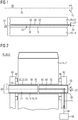
- FIG 1 the structure of an embodiment of the claimed slide bearing 30 is shown schematically, which comprises a first bearing component 10 and a second bearing component 20 and belongs to a slide bearing arrangement 40, not shown in detail.
- the first bearing component 10 and the second bearing component 20 are movable relative to one another about an axis of rotation 15, that is to say rotatable.
- a rotation of the slide bearing 30 is shown by the arrow 25.
- the first bearing component 10 has a surface 12 that is a surface 22 of the second Bearing component 20 is facing.
- a lubricant film 35 is formed between the mutually facing surfaces 12, 22 of the first and second bearing components 10, 20 and is produced by a supply of lubricant 36.
- the first bearing component 10 has a base material 14 to which a plain bearing material 16 is applied at least in sections, so that the surface 12 of the first bearing component 10 facing the second bearing component 20 is formed by the plain bearing material 16.
- a sliding coating 26 is applied to the surface 22 of the second bearing component 20 on the surface 22 of the second bearing component 20.
- the sliding coating 26 and the sliding bearing material 16 each have a reduced surface roughness and form a low-wear tribological system.
- the first and second bearing components 20 slide on one another along a contact surface 33, the rotation 25 being supported by the lubricant film 35.
- the sliding coating 26 has a thickness 27 of 3 ⁇ m to 20 ⁇ m and is at least partially made of polytetrafluoroethylene, perfluoroalkoxy copolymers, polyfluoroalkoxy-polytetrafluoroethylene copolymers, ethylene tetrafluoroethylene, polychlorotrifluoroethylene, fluorinated ethylene-propylene copolymers, polyvinyl fluoride, polyvinylidene fluoride, alternating copolymers such as perfluoroethylene propylene, polyester imides, bismaleimides, polyimide resins such as carboranimides, aromatic polyimide resins, hydrogen-free polyimide resins, polytriazo pyromellithimides, polyamide imides, in particular aromatic, polyaryl ether imides, optionally modified with isocyanates, epoxy resins, optionally modified with isocyanates, epoxy resins, optionally modified with isocyanates, epoxy resins Polyamide 6, polyamide 66, polyoxym
- the basic material 24 of the second bearing component 20 is steel, cast iron or cast steel. Accordingly, there is advantageous mutual adhesion for the base material 24 and the sliding coating 26 of the second bearing component 20.
- An existing roughness profile of the base material 24 of the second bearing component 20 is at least partially covered by the sliding coating 26. As a result, the tribological system with the sliding bearing material 16 and the sliding coating 26 on the contact surface 33 is independent of the base material 24 of the second bearing component 20.
- the plain bearing material 16 is at least partially made of bronze, brass, ceramic, white metal, a CuZn alloy, an AlZn alloy, a CuAl alloy, an AlSi alloy, an AlSnSi alloy, a CuSnZn alloy, a CuBi alloy , a bismuth alloy, a silver alloy, an AlBi alloy AlSn20Cu, AlZn4Si3 or AlZnSi4.5.
- Said plain bearing materials 16 show an advantageous run-in behavior when they come into contact with the abovementioned slide coatings 26. As a result, a run-in phase for the plain bearing 30 is shortened or completely dispensed with. A large number of advantageous material pairings result for the sliding bearing material 16 and the sliding coating 26.
- FIG 2 shows schematically the structure of an embodiment of the claimed slide bearing arrangement 40, which belongs to a transmission 50 (not shown in detail) with a housing 51 (not shown in detail).
- the slide bearing arrangement 40 comprises an axle 41 which serves as a stationary first bearing component 10 of a slide bearing 30.
- the axis 41 is received at its ends in walls 43, which are designed as cheeks of a planet carrier, on which thrust washers 46 are arranged.
- the slide bearing arrangement 40 also comprises a gearwheel 42 which is received on the axis 41 so as to be rotatable about an axis of rotation 15.
- the gear 42 serves in the plain bearing arrangement 40 as a movable, that is, rotatable second bearing component 20. A rotation of gear 42 is symbolized by arrow 25.
- recesses 44 are formed in the axis 41 and a cheek 43, through which the lubricant 35 is conveyed via the pump 36.
- the lubricant 35 forms a lubricant film 36 on a contact surface 33, so that the first bearing component 10 forms a slide bearing 30 with the second bearing component 20.
- the contact surface 33 is in FIG 2 essentially cylindrical.
- the first bearing component 10 comprises the axis 41, which also forms the base material 14, on the surface 12 of which a plain bearing material 16 is attached circumferentially.
- the plain bearing material 16 forms a bearing bush 19.
- the plain bearing material 16 covers the axis 41, that is to say the base material 14, at least partially along the axis of rotation 15.
- the plain bearing material 16 is provided with a coating 18, by means of which the surface 12 of the first bearing component 18 is further smoothed, that is to say has a reduced surface roughness.
- An inner side 45 of the gearwheel 42 is arranged opposite the plain bearing material 16, which in the assembled state surrounds the plain bearing material 16 all the way along the gearwheel 42.
- the gear 42 serves as the second bearing component 20 of the slide bearing 30 and forms a base material 24 of the second bearing component 20.
- the inside 45 of the gear 42 thereby forms a surface 22 of the second bearing component 20 and is provided with a slide coating 26.
- the sliding coating 26, corresponding to the sliding bearing material 16, is also applied circumferentially on the surface 12, that is to say the axis 41.
- the surfaces 12, 22 of the first and second bearing components 10, 20 are formed circumferentially and face one another.
- the gear 42, and thus the second bearing component 20 slides on the axle 41, that is to say the first bearing component 10, these being only separated by the lubricant film 35.
- a roughness profile of the axis 41 is covered by the sliding coating 26.
- a further reduced coefficient of friction is achieved, which in turn ensures a reduced risk of spontaneous failure of the sliding bearing 30.
- the wind power plant 70 comprises a drive train 60, which is received in a nacelle 61, to which a rotor 62 is attached.
- the drive train 60 comprises a rotor shaft 64, a gear 50 and a generator 66.
- the rotor 62 is connected to the rotor shaft 64, which in turn is coupled to the gear 50 to transmit torque.
- the transmission 50 is connected to the generator 66 in a torque-transmitting manner.
- the gear 50 is designed as a planetary gear and has at least one slide bearing arrangement 40 according to one of the embodiments outlined above. Accordingly, the at least one slide bearing arrangement 40 has a slide bearing 30 which is designed according to one of the embodiments described above.
- FIG 4 shows schematically the structure of an embodiment of a claimed industrial application 80.
- the industrial application 80 comprises an output unit 82, which can be designed, for example, as an electric motor, internal combustion engine or hydraulic motor.
- a drive power that is to say a rotation 25, is made available by the drive unit 82 and is fed to a gear 50. With conversion of the present speed and the present torque, the drive power is fed to an output unit 84.
- the output unit 84 can, for example, be designed as a mechanical application, so that the industrial application 80 can be used as a mill, vertical mill, sugar mill, cement mill, rock crusher, conveyor belt, pump, roller press, apron conveyor, tube mill, rotary kiln, rotating mechanism, agitator, lifting device, waste compactor or scrap press is trained.
- the transmission 50 via which the drive unit 82 is connected to the output unit 84, designed according to one of the embodiments outlined above. Accordingly, the transmission 50 is provided with at least one slide bearing arrangement 40 according to one of the embodiments shown above and has a slide bearing 30 according to at least one of the embodiments described above.
Landscapes
- Engineering & Computer Science (AREA)
- General Engineering & Computer Science (AREA)
- Mechanical Engineering (AREA)
- Manufacturing & Machinery (AREA)
- Sliding-Contact Bearings (AREA)
Priority Applications (1)
| Application Number | Priority Date | Filing Date | Title |
|---|---|---|---|
| EP20174148.5A EP3910206A1 (fr) | 2020-05-12 | 2020-05-12 | Palier lisse, agencement de palier lisse, boîte de vitesses et chaine cinématique pour éoliennes |
Applications Claiming Priority (1)
| Application Number | Priority Date | Filing Date | Title |
|---|---|---|---|
| EP20174148.5A EP3910206A1 (fr) | 2020-05-12 | 2020-05-12 | Palier lisse, agencement de palier lisse, boîte de vitesses et chaine cinématique pour éoliennes |
Publications (1)
| Publication Number | Publication Date |
|---|---|
| EP3910206A1 true EP3910206A1 (fr) | 2021-11-17 |
Family
ID=70682618
Family Applications (1)
| Application Number | Title | Priority Date | Filing Date |
|---|---|---|---|
| EP20174148.5A Withdrawn EP3910206A1 (fr) | 2020-05-12 | 2020-05-12 | Palier lisse, agencement de palier lisse, boîte de vitesses et chaine cinématique pour éoliennes |
Country Status (1)
| Country | Link |
|---|---|
| EP (1) | EP3910206A1 (fr) |
Citations (10)
| Publication number | Priority date | Publication date | Assignee | Title |
|---|---|---|---|---|
| EP1520779A2 (fr) * | 2003-09-30 | 2005-04-06 | B+V Industrietechnik GmbH | Dispositif de palier pivotant |
| DE102007058627A1 (de) | 2007-12-05 | 2009-06-18 | Ibg Monforts Fluorkunststoffe Gmbh & Co. Kg | Gleitlager eines Bauwerks |
| US20100124388A1 (en) * | 2008-11-19 | 2010-05-20 | Than Trong Long | Composite bearing member, manufacturing method of composite bearing member, bearing device and rotary electrical machine |
| US20110172048A1 (en) * | 2009-08-26 | 2011-07-14 | Mitsubishi Heavy Industries, Ltd. | Planetary bearing structure |
| WO2011127509A1 (fr) | 2010-04-14 | 2011-10-20 | Miba Gleitlager Gmbh | Engrenage pour une éolienne |
| WO2012071639A1 (fr) * | 2010-12-03 | 2012-06-07 | Whirlpool S.A. | Paire tribologique et procédé pour le traitement de surface dans des paires tribologiques |
| US20130188898A1 (en) * | 2012-01-20 | 2013-07-25 | Miba Gleitlager Gmbh | Solid bronze bearing with hardness gradient |
| EP2662598A1 (fr) * | 2012-05-08 | 2013-11-13 | ZF Wind Power Antwerpen NV | Étage d'engrenage planétaire avec des paliers lisses en tant que roulements planétaires |
| DE102016013451A1 (de) | 2016-11-10 | 2017-06-14 | Daimler Ag | Laseranordnung zur Lagerung einer Kurbelwelle |
| US20170286572A1 (en) | 2016-03-31 | 2017-10-05 | General Electric Company | Digital twin of twinned physical system |
-
2020
- 2020-05-12 EP EP20174148.5A patent/EP3910206A1/fr not_active Withdrawn
Patent Citations (10)
| Publication number | Priority date | Publication date | Assignee | Title |
|---|---|---|---|---|
| EP1520779A2 (fr) * | 2003-09-30 | 2005-04-06 | B+V Industrietechnik GmbH | Dispositif de palier pivotant |
| DE102007058627A1 (de) | 2007-12-05 | 2009-06-18 | Ibg Monforts Fluorkunststoffe Gmbh & Co. Kg | Gleitlager eines Bauwerks |
| US20100124388A1 (en) * | 2008-11-19 | 2010-05-20 | Than Trong Long | Composite bearing member, manufacturing method of composite bearing member, bearing device and rotary electrical machine |
| US20110172048A1 (en) * | 2009-08-26 | 2011-07-14 | Mitsubishi Heavy Industries, Ltd. | Planetary bearing structure |
| WO2011127509A1 (fr) | 2010-04-14 | 2011-10-20 | Miba Gleitlager Gmbh | Engrenage pour une éolienne |
| WO2012071639A1 (fr) * | 2010-12-03 | 2012-06-07 | Whirlpool S.A. | Paire tribologique et procédé pour le traitement de surface dans des paires tribologiques |
| US20130188898A1 (en) * | 2012-01-20 | 2013-07-25 | Miba Gleitlager Gmbh | Solid bronze bearing with hardness gradient |
| EP2662598A1 (fr) * | 2012-05-08 | 2013-11-13 | ZF Wind Power Antwerpen NV | Étage d'engrenage planétaire avec des paliers lisses en tant que roulements planétaires |
| US20170286572A1 (en) | 2016-03-31 | 2017-10-05 | General Electric Company | Digital twin of twinned physical system |
| DE102016013451A1 (de) | 2016-11-10 | 2017-06-14 | Daimler Ag | Laseranordnung zur Lagerung einer Kurbelwelle |
Similar Documents
| Publication | Publication Date | Title |
|---|---|---|
| AT509624B1 (de) | Windkraftanlage | |
| EP3396187B1 (fr) | Procédé de fabrication d'un coussinet de palier lisse | |
| EP3001071B1 (fr) | Barre planétaire - alésage d'huile | |
| EP1847713B1 (fr) | Pompe rotative réglable à usure réduite | |
| EP3631203A1 (fr) | Transmission d'éolienne | |
| EP1951443B1 (fr) | Composant, en particulier une pièce moulée comprenant un revêtement | |
| WO2003019004A1 (fr) | Lubrification pour dispositif de reglage d'angle d'attaque sur une pale de rotor d'eolienne | |
| DE102012223042A1 (de) | Gleitlagerverbundwerkstoff | |
| WO2020118336A1 (fr) | Engrenage pour éolienne comprenant au moins un palier lisse | |
| WO2019052903A1 (fr) | Vernis de glissement, élément de glissement pourvu d'un tel vernis et utilisation de celui-ci | |
| EP3404294A1 (fr) | Engrenage, en particulier pour générateurs éoliens | |
| EP3894715A1 (fr) | Nacelle pour une éolienne | |
| WO2022043080A1 (fr) | Boîte de vitesses à trains épicycloïdaux à transfert de lubrifiant amélioré, chaîne cinématique, éolienne et application industrielle | |
| EP4298359B1 (fr) | Engrenage épicycloïdal à alimentation en lubrifiant améliorée, chaîne cinématique et éolienne | |
| DE102016204199A1 (de) | Zahnradpumpe für ein Abwärmerückgewinnungssystem | |
| EP1183476B1 (fr) | Element de palier de butee | |
| DE102017118067A1 (de) | Motorradantriebskette mit gleitlackbeschichteter Hülse | |
| DE102023101335A1 (de) | Verbesserter Gleitbelag sowie Anwendungen dieses | |
| DE102008044109A1 (de) | Wellgetriebe | |
| EP4043756A1 (fr) | Ensemble porte-satellites, engrenage planétaire, chaîne cinématique, éolienne et produit programme informatique | |
| WO2017009223A1 (fr) | Palier lisse pour une boîte de vitesses d'éolienne | |
| EP4050227A1 (fr) | Palier lisse, engrenage, éolienne et procédé de fabrication | |
| EP4291805B1 (fr) | Ensemble porte-satellites, engrenage planétaire, chaîne cinématique, éolienne | |
| DE102023118943A1 (de) | Profiliertes Gleitsegment und dessen Anwendung | |
| DE102024209922A1 (de) | Getriebe für eine Antriebseinheit eines Flurförderfahrzeugs oder einer Arbeitsmaschine, Antriebseinheit für ein Flurförderfahrzeug oder eine Arbeitsmaschine und Flurförderfahrzeug oder einer Arbeitsmaschine |
Legal Events
| Date | Code | Title | Description |
|---|---|---|---|
| PUAI | Public reference made under article 153(3) epc to a published international application that has entered the european phase |
Free format text: ORIGINAL CODE: 0009012 |
|
| STAA | Information on the status of an ep patent application or granted ep patent |
Free format text: STATUS: THE APPLICATION HAS BEEN PUBLISHED |
|
| AK | Designated contracting states |
Kind code of ref document: A1 Designated state(s): AL AT BE BG CH CY CZ DE DK EE ES FI FR GB GR HR HU IE IS IT LI LT LU LV MC MK MT NL NO PL PT RO RS SE SI SK SM TR |
|
| B565 | Issuance of search results under rule 164(2) epc |
Effective date: 20201102 |
|
| STAA | Information on the status of an ep patent application or granted ep patent |
Free format text: STATUS: THE APPLICATION IS DEEMED TO BE WITHDRAWN |
|
| 18D | Application deemed to be withdrawn |
Effective date: 20220518 |