EP3910310A1 - Messung von polarisationsabhängigen verlusten - Google Patents
Messung von polarisationsabhängigen verlusten Download PDFInfo
- Publication number
- EP3910310A1 EP3910310A1 EP21172895.1A EP21172895A EP3910310A1 EP 3910310 A1 EP3910310 A1 EP 3910310A1 EP 21172895 A EP21172895 A EP 21172895A EP 3910310 A1 EP3910310 A1 EP 3910310A1
- Authority
- EP
- European Patent Office
- Prior art keywords
- sop
- lightwave
- dut
- input
- test
- Prior art date
- Legal status (The legal status is an assumption and is not a legal conclusion. Google has not performed a legal analysis and makes no representation as to the accuracy of the status listed.)
- Granted
Links
Images


Classifications
-
- G—PHYSICS
- G01—MEASURING; TESTING
- G01M—TESTING STATIC OR DYNAMIC BALANCE OF MACHINES OR STRUCTURES; TESTING OF STRUCTURES OR APPARATUS, NOT OTHERWISE PROVIDED FOR
- G01M11/00—Testing of optical apparatus; Testing structures by optical methods not otherwise provided for
- G01M11/30—Testing of optical devices, constituted by fibre optics or optical waveguides
- G01M11/33—Testing of optical devices, constituted by fibre optics or optical waveguides with a light emitter being disposed at one fibre or waveguide end-face, and a light receiver at the other end-face
- G01M11/337—Testing of optical devices, constituted by fibre optics or optical waveguides with a light emitter being disposed at one fibre or waveguide end-face, and a light receiver at the other end-face by measuring polarization dependent loss [PDL]
-
- G—PHYSICS
- G01—MEASURING; TESTING
- G01J—MEASUREMENT OF INTENSITY, VELOCITY, SPECTRAL CONTENT, POLARISATION, PHASE OR PULSE CHARACTERISTICS OF INFRARED, VISIBLE OR ULTRAVIOLET LIGHT; COLORIMETRY; RADIATION PYROMETRY
- G01J4/00—Measuring polarisation of light
- G01J4/04—Polarimeters using electric detection means
-
- G—PHYSICS
- G01—MEASURING; TESTING
- G01M—TESTING STATIC OR DYNAMIC BALANCE OF MACHINES OR STRUCTURES; TESTING OF STRUCTURES OR APPARATUS, NOT OTHERWISE PROVIDED FOR
- G01M11/00—Testing of optical apparatus; Testing structures by optical methods not otherwise provided for
- G01M11/30—Testing of optical devices, constituted by fibre optics or optical waveguides
- G01M11/33—Testing of optical devices, constituted by fibre optics or optical waveguides with a light emitter being disposed at one fibre or waveguide end-face, and a light receiver at the other end-face
- G01M11/331—Testing of optical devices, constituted by fibre optics or optical waveguides with a light emitter being disposed at one fibre or waveguide end-face, and a light receiver at the other end-face by using interferometer
-
- G—PHYSICS
- G01—MEASURING; TESTING
- G01M—TESTING STATIC OR DYNAMIC BALANCE OF MACHINES OR STRUCTURES; TESTING OF STRUCTURES OR APPARATUS, NOT OTHERWISE PROVIDED FOR
- G01M11/00—Testing of optical apparatus; Testing structures by optical methods not otherwise provided for
- G01M11/30—Testing of optical devices, constituted by fibre optics or optical waveguides
- G01M11/33—Testing of optical devices, constituted by fibre optics or optical waveguides with a light emitter being disposed at one fibre or waveguide end-face, and a light receiver at the other end-face
- G01M11/335—Testing of optical devices, constituted by fibre optics or optical waveguides with a light emitter being disposed at one fibre or waveguide end-face, and a light receiver at the other end-face using two or more input wavelengths
Definitions
- the present description generally relates to polarization dependent loss (PDL) measurement, and more particularly to measuring polarization dependent loss of a device under test using a single spectral scan.
- PDL polarization dependent loss
- PDL Polarization Dependent Loss
- the Polarization Scanning technique the Device Under Test (DUT) is exposed to virtually all States Of Polarization (SOP) and the PDL is determined from the maximum and minimum power transmission through the DUT. Because the Polarization Scanning technique needs to expose the DUT to many states of polarization, the PDL is measured at a single wavelength at a time. Measuring the PDL over a broad wavelength range can quickly become impractical.
- the classic Mueller Matrix Method aims at determining the first row of the Mueller matrix (4 elements) that characterizes the DUT, from which the PDL of the DUT is deduced.
- a lightwave having successively a small number (e.g. 4) of distinct, known input states of polarizations (SOP) is launched into the DUT, and the corresponding small number of power transmissions are measured (power of the lightwave at the output of the DUT divided by the power at the input of the DUT).
- distinct wavelength scans need to be performed sequentially for each of said small number of distinct input-SOPs (minimum of 4), wherein the input-SOP is fixed (constant as a function of time) during each individual scan.
- the classic Mueller Matrix Method is prone to substantial errors should the DUT be unstable over the interval between said sequential wavelength scans, e.g., due to moving patch-cords, in which case the PDL measurement can be utterly wrong.
- a single wavelength scan approach would resolve this problem by making the SOP of the input test lightwave vary rapidly during the wavelength scan, so the DUT response to a plurality of input-SOPs would be measured at each wavelength within a much shorter time.
- a method was proposed in the art (see US 6,856,386 to Anderson ) to measure the PDL based on the Mueller Matrix Method but using a single wavelength scan, by changing the input-SOP during the wavelength scan in a cyclic manner.
- the input-SOP can be changed using either an active or a passive device.
- one drawback of this method is that it requires that the SOP of the input test lightwave be either carefully controlled or monitored using a polarimeter and, in the case of a passive SOP generator, the combination of a polarimeter and additional polarization controller in an feedback loop, which significantly increases the difficulty of implementation, complexity and cost of the test hardware.
- the new set of equations is applied to derive the same result, i.e., the 4-element response vector of the DUT (elsewhere referred to as the first row of the Mueller matrix) as a function of optical frequency (or wavelength), from a different data set obtained by a different data acquisition procedure, i.e., a single wavelength scan over which the input-SOP varies continuously over the scan instead of a few sequential scans with fixed SOPs.
- a method for measuring the PDL of a DUT as a function of optical frequency v within a spectral range which uses a single wavelength scan over which the input-SOP varies in a continuous manner, i.e. not a finite number of discrete points, but a continuous trajectory on the surface of the Poincaré sphere as a function of v.
- the PDL is derived from the resolved sideband components of the power transmission curve T(v) that result from the continuously varying input-SOP. More specifically, the Discrete Fourier Transform (DFT) of the power transmission curve T(v) is calculated, wherein the DFT shows at least two resolved sidebands in the delay ( ⁇ ) domain (four in the hereindescribed embodiment), where delay ⁇ is the conjugate variable of v in the Fourier transform (the same way as signal-frequency f is the conjugate variable of time t). At least two sidebands are extracted individually, i.e.
- DFT Discrete Fourier Transform
- the transmissions are complex in the sense that they are complex numbers (real and imaginary parts, or equivalently, amplitude and phase).
- m(v) ⁇ of the DUT, elsewhere referred to as the first line of the Mueller matrix, is derived from the complex transmissions and a matrix that represents a system of equations to be solved.
- a system of equations can be advantageously solved by arranging the known coefficients into a matrix, and inverting said matrix.
- the provided method allows for asynchronous sampling of the power transmission curve T(v) with respect to the variation of the input-SOP, i.e. the sampled points do not need to fall on specific input-SOPs.
- This property allows to circumvent the need for monitoring the input-SOP with a polarimeter in the case of an active SOP generator (see active SOP generator approach of US 6,856,386 ), or to additionally control the SOP through a feedback loop in the case of a passive SOP generator (see passive SOP generator approach of US 6,856,386 ).
- measuring the power transmission curve T(v) comprises data sampling that is allowed to be asynchronous with respect to the SOP variation of the input test lightwave, i.e. the sampled points do not need to fall on a pre-determined set of input-SOPs, and consequently, the most usual and simple kind of sampling can be performed, i.e. sampling at equal intervals dv between successive samples, regardless of the input-SOP at the values of v corresponding to the samples.
- the phase of the SOP of the input lightwave along the continuous trajectory i.e. where exactly along the trajectory is the point that represents the SOP at a given value of v, may be either known or measured at each sampled point.
- phase reference signal P ⁇ in the detailed description
- a method for measuring the PDL of a DUT within a spectral range comprises:
- the apparatus comprises:
- wave length scan and “spectral scan” are used interchangeably herein to denote a scan that varies the optical frequency v and the wavelength ⁇ of a lightwave over a spectral range.
- word modifiers such as “substantially” and “about” which modify a value, condition, relationship or characteristic of a feature or features of an embodiment, should be understood to mean that the value, condition, relationship or characteristic is defined to within tolerances that are acceptable for proper operation of this embodiment in the context of its intended application.
- connection or coupling refers to any connection or coupling, either direct or indirect, between two or more elements.
- the connection or coupling between the elements may be mechanical, physical, operational, electrical or a combination thereof.
- m(v) ⁇ is obtained by solving a linear system of equations, where the four unknowns to be determined are the four elements of the response vector.
- the coefficients that multiply the unknowns in the different equations can be grouped to form a single matrix, say matrix A (not to be confused with the Mueller matrix), and the solution of the system of equations is obtained by first computing the inverse of A.
- the equivalent of the time-varying signal bandwidth is the "DUT extent" in the delay domain ( ⁇ ), i.e. how large is the Fourier transform of the DUT transmission curve T DUT (v).
- the DUT is a narrow optical filter such as a WDM filter
- the narrower T DUT (v) the larger its extent in the delay domain.
- the spacing between the sideband-carriers are set larger than the maximum extent of the DUT that is expected to be encountered. This spacing is a characteristic of the SOP generator that one can set in accordance with the expected application of the instrument, i.e. large enough for the sidebands not to overlap for DUTs having the largest expected extent (typically DUTs that have the narrowest and/or sharpest transmission T DUT (v)).
- the result of the measurement of the RSB method is the 4-element response vector
- the PDL can be derived as known in the art, in the same way as in the classic Mueller Matrix Method.
- the polarization-dependent center wavelength (PDCW) and the polarization-dependent bandwidth (PDBW) of the DUT can also be derived as known in the art from
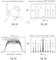
- Figs. 1A to 1D are used to illustrate the oscillating components of T(v) appearing as sidebands in the delay domain ( ⁇ ) (see Fig. 1D-1F ).
- the trajectory shown in Fig. 1 is one among an infinity of possible trajectories.
- the SOP at a given value of v corresponds to one point on the surface of the Poincaré sphere (a representation widely used in the art to depict the SOP).
- the trajectory is the overall path followed by the input-SOP on the surface of the Poincaré sphere.
- Fig. 1B shows the DFT (discrete Fourier transform) of the example trajectory of Fig. 1A ; since ⁇ (v) is a 3-element vector, there are in fact three such DFTs, one DFT for each of the Stokes parameters (coordinates); but to simplify, Fig. 1B regroups the three curves into a single one given by the root-mean-square value of the three DFTs at each point v, which suffices to illustrate the DFT of the example trajectory ⁇ (v) of Fig. 1A .
- T(v) has a much larger extent than needed in the delay domain.
- the photodetector electronics should have a larger bandwidth, which generally results in both a larger noise spectral-density and smaller signal-to-noise ratio for a given input power.
- Fig. 1A Because the example trajectory of Fig. 1A is periodical, the discrete sidebands in its Fourier transform are equally spaced. But the RSB method does not require a periodical trajectory, nor equal spacing of the sidebands. However, it may be more judicious in practice to target a substantially equal spacing in order to best separate the sidebands from one another within some given total delay range.
- Fig. 1C shows the power transmission curve T(v) through an example DUT, in response to the input-SOP trajectory of Fig. 1A .
- the example DUT is an optical filter having a passband of 30 GHz (FWHM) and a PDL of 3 dB.
- Fig. 1D shows the DFT of the power transmission curve T(v) shown in Fig. 1C .
- each sinusoidally oscillating input-SOP component l (complex phasor) ( Fig.1B , 1E ) generates a sideband l around carrier-delay ⁇ l in the DFT of T(v) ( Fig.1D , 1F ).
- v ⁇ is a column vector that may have any number of either real or complex-valued elements
- is the transposed complex-conjugate of
- bracket notation ⁇ vlv' ⁇ represents the scalar product defined as, bra: ⁇ v
- v 0 * v 1 * v 2 * ... v n ⁇ 1 * , where * means complex-conjuguate.
- T ⁇ ⁇ s ⁇
- m ⁇ ⁇ with T(v) P out (v)/P in (v), where Pin(v) and P out (v) are the power of the lightwave at input and output of the DUT,
- m(v) ⁇ (m 0 (v) m 1 (v) m 2 (v) m 3 (v) ) ⁇ is said response vector of the DUT measured by the method, and ⁇ s(v)
- (1s 1 (v) s 2 (v) s 3 (v)) ⁇ is the 4-element bra representing the 100% polarized input-SOP, where the last three elements of (s(v)
- are those of the 3-element unit Stokes vector ⁇ (v) (s 1 (v) s 2 (v) s(v)) ⁇ ,
- 1.
- each component z l e i ⁇ l of ⁇ (v) generates one and only one term in sum (3), which translates as sideband l around carrier-delay ⁇ l in the DFT of T(v) as shown in Fig. 1F .
- (1) implies that complex transmissions are given by, where ⁇ z l
- a suitable trajectory of the input-SOP as a function of v as described hereinabove is generated using a passive SOP generator.
- suitable trajectories of the input-SOP may be generated by using an actively controlled SOP generator.
- Such actively controlled SOP generators are generally known in the art and commercially available and will therefore not be herein described in detail. Actively controlled SOP generators are also much more complex, bulky and costly.
- Fig. 2 shows a passive SOP generator in accordance with one embodiment that is used to illustrate the physical principle.
- the passive SOP generator is based on a twosegment PMD emulator, abbreviated as the 2-segs from hereon.
- an input polarized ligthwave i.e. the output of a spectrally scanned polarized light source
- successively passes through a first segment Sego and a second segment Seg 1 .
- Each segment Sego, Seg 1 is characterized by a Principal State of Polarization (PSP) that is constant as a function of v and a Differential Group Delay (DGD) that may or may not be constant over the relevant spectral range but is herein assumed constant for simplicity.
- PSP Principal State of Polarization
- DGD Differential Group Delay
- Each segment Sego, Seg 1 acts as a 3D rotation on the 3-elementStokes vector that represents the SOP.
- the output-SOP ⁇ (v) is thus given by the product of these two rotations applied to the input-SOP ⁇ o .
- the first and second segments are embodied by pieces of Polarisation Maintaining Fibers (PMFs).
- PMFs Polarisation Maintaining Fibers
- the input-SOP ⁇ o and the PSPs p 0 , p 1 of respective segments Sego, Seg 1 are 3-element unit Stokes vectors.
- the DGDs of segments Sego, Seg 1 are respectively noted ⁇ 0 and ⁇ 1 .
- the coupling angles ⁇ ⁇ o and ⁇ p are respectively the angle between ⁇ o and p 0 and the angle between p 0 and p 1 .
- Parameter r is the ratio of the DGD ⁇ 0 of segment Seg 0 over the DGD ⁇ 1 of segment Seg 1 .
- the 2-segs may be designed to obtain a ratio r that is substantially an integer value such as 1, 2 or 3, so as to advantageously obtain substantially equally-spaced sidebands. There is however no requirement that the ratio r be a strictly integer value.
- the number of distinct (not superimposed) sidebands in the Fourier transform of the transmission T(v) depends on the ratio r.
- Fig. 3 shows a passive SOP generator 300 in accordance with one practical implementation of the 2-segs of Fig. 2 which is based on PMF fibers only.
- the passive SOP generator 300 comprises two concatenated pieces of PMF 302, 304 and an input polarizer 306. It also comprises an optional phase reference arm 310.
- the input polarizer 306 sets the SOP at the input of the first piece of PMF 302, and thus the coupling angle ⁇ ⁇ o .
- the two pieces of PMF 302, 304 are fused at an angle ⁇ p between their respective PSPs ( p 0 and p 1 ).
- the specific values of the coupling angles ⁇ ⁇ o and ⁇ p are not critical in the sense that no high precision alignment is required, as long as the actual angles are known or determined afterwards.
- the actual coupling angles ⁇ ⁇ o and ⁇ p can be determined afterwards through a calibration process, e.g. using a polarimeter.
- Respective lengths of PMF pieces 302, 304 determine the value of their DGDs ⁇ 0 , ⁇ 1 , thus also the ratio r.
- the two DGDs may be effectively measured live through appropriate data processing of the phase reference signal P ⁇ (v). More to the point, the two effective DGDs determine the phase of the SOP of the input lightwave along the trajectory, i.e. where exactly along the trajectory is the point that represents the SOP located at a given value of v. This phase may be either known or measured at each sampled point.
- One may target design values of angles ⁇ ⁇ o and ⁇ p , DGD ⁇ 0 and DGD ⁇ 1 with reasonable care, but the true angles and DGDs after assembly do not need to be precisely equal to the design values.
- the phase reference arm 310 comprises a coupler 308 used to extract a small portion of the light at the output of the second PMF piece 304 toward a polarizer 312 (analyzer â ) followed by a photodetector 314, which output constitutes a phase reference signal P ⁇ (v).
- This phase reference signal would not be needed in a perfect world where the DGDs and corresponding phases ⁇ 0 (v), ⁇ 1 (v) (see Fig.2 ) would be exactly known.
- the phase reference serves the following purpose: from the sampled signal P ⁇ (v), said phases ⁇ 0 (v), ⁇ 1 (v) (angles of rotation) are deduced at each sampled point of the spectral scan through appropriate data processing. There is therefore no need for the DGDs to be accurately known in advance, infinitely stable and constant as a function of v.
- the input polarizer 306 and phase reference arm 310 may be made of bulk components or optical fiber components (i.e. polarizers, coupler or beamsplitter).
- the angle ⁇ â between â and p 1 is set by rotating polarizer 312 (or by an angular fusion splice between the second PMF piece 304 and the PMF-fiber pigtail of the polarizer 312).
- ⁇ â is set to roughly 45° (not critical, but it should not be 0°, 90° or 180°, because then either one of the oscillating components of the signal P ⁇ (v) that are analyzed in the data processing to measure said phases live would have zero amplitude).
- the embodiment of Fig. 3 may suffer from a non-negligible drawback is some cases.
- DGD values e.g. in the nanoseconds order of magnitude or even greater if needed, may be obtained by replacing the PMF pieces 302, 304 by devices 402, 404 which may be named Polarization-Splitting Mach-Zehnder interferometers PS_MZ.
- Fig. 4 shows a passive SOP generator 400 in accordance with another practical implementation of the 2-segs of Fig. 2 , which is based on such PS_MZs.
- This bulk-and-fiber PS_MZ embodiment overcomes the above-mentioned drawback of the all-fiber embodiment of Fig. 3 .
- the optical path is split in two arms and then recombined using two Polarization Beam Splitters (PBS) 416.
- PBS Polarization Beam Splitters
- a path length difference (delay) between the two arms is set by a piece of fiber 418 inserted in one of the arms, preferably a piece of PMF fiber in order to minimize and stabilize the effective loss of the corresponding arm.
- each PS_MZ device 402, 404 is equal to the delay between the two arms, which is roughly equal to the path length of said piece of PMF fiber.
- a 3-ns DGD may be obtained using a PMF length of about 60 cm for a typical fiber with a refractive index of 1.5, which is indeed much less than the 2 km needed in the embodiment of Fig. 3 .
- the PSP is determined by the polarization axis of the PBSs. Multiple collimating lenses used along the optical paths are denoted c 1 to c 8 .
- the passive SOP generator 400 also comprises an optional phase reference arm 410. As in the embodiment of Fig. 3 , a small proportion of the light at the output of the second PS_MZ device 404 is extracted by a coupler 408 toward polarizer 412 followed by photodetector 414 which output constitutes the phase reference signal P ⁇ (v).
- the coupling angle ⁇ ⁇ o is set by rotating the assembly comprising the input polarizer 406 and collimator co.
- the coupling angle ⁇ p is set by the angled fusion between the two pieces of PMF 420, 422 attached respectively to collimators c 3 and c 4 .
- the PSP of each of these two pieces of PMF 420, 422 is aligned with the polarization axis of the PBS that faces the collimator to which they are attached.
- the angle ⁇ â between â and p 1 is set by rotating polarizer 412.
- the lengths of the PMF pieces 418 (denoted PMFo and PMF 1 ) mainly determine the DGDs of the two PS_MZs 402, 404: ⁇ q ⁇ n L q /c, wherein L q is the PMF length and n is the mean group index of the fiber ( ⁇ 1.5).
- L q is the PMF length
- n is the mean group index of the fiber ( ⁇ 1.5).
- Collimators c 3 and c 4 and their attached pieces of PMF are inserted for the purpose of simplifying the assembly.
- Fig. 5 shows a passive SOP generator 500 in accordance with another practical implementation of the 2-segs of Fig. 2 , which is based on all-bulk PS_MZs.
- the passive SOP generator 500 comprises two all-bulk PS_MZs 502, 504.
- the optical path is split in two arms and then recombined using two Polarization Beam Splitters (PBS) 516.
- PBS Polarization Beam Splitters
- a path length difference (delay) between the two arms is set by a free-space optical path that is made longer in one of the arms 518, using a mirror arrangement.
- the DGD of each PS_MZ 502, 504 is equal to the delay between the two arms.
- the passive SOP generator 500 also comprises an input polarizer 506, and again, as in the embodiment of Fig. 3 , a small proportion of the light at the output of the second PS_MZ 504 is extracted by a beam splitter 508 toward a phase reference arm 510 which output is the phase reference signal P ⁇ (v).
- the coupling angle ⁇ ⁇ o is set by rotating the input polarizer 506.
- the coupling angle ⁇ p is set by rotating the mounting plane of the second PS_MZ 504 (normal û 1 ) with respect to the mounting plane of the first PS_MZ 502 (normal û 0 ).
- the two PS_MZs 502, 504 may alternatively be mounted on the same plane by inserting a retardation waveplate ( ⁇ /2) in-between.
- the coupling angle ⁇ p is then set by rotating the waveplate.
- phase reference arm 310 or 410 may be replaced by the bulk phase reference arm 510 and vice versa.
- the bulk delay lines 518 of the all-bulk embodiment 500 may also be replaced by segments of PMF and associated collimator lenses c 1 -c 2 , c 5 -c 6 as in the bulk and fiber embodiment 400.
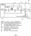
- Fig. 6 shows a PDL measurement system 600 in accordance with one embodiment which employs a single spectral scan and a passive SOP generator.
- the RBS method notably its new mathematics (see equations (1) to (10)) constituting a generalization of the mathematics of the classic Mueller Matrix Method, is more general than this embodiment, is not limited to this embodiment and does not require data to be acquired using a single wavelength scan. It rather allows dealing optimally with this much more challenging case. Data may as well be acquired using multiple scans sequentially in time with different oscillating SOPs, and whether the SOP generator is active or passive.
- the PDL measurement system 600 is still mostly advantageous compared to the classic Mueller Matrix Method in that the PDL can be derived from a single wavelength scan over which the input-SOP continuously varies instead of a few sequential scans with fixed SOPs.
- the PDL measurement system 600 comprises a tunable light source 602, an SOP generator 604, a power transmission measurement apparatus 606, an acquisition device 608 (also referred to as data sampling), a processing unit 610 implementing the RSB data processing, a data output 612 for displaying, saving in memory or otherwise outputting the measurement results.
- the tunable light source 602 generates a test lightwave and spectrally scans the test lightwave over the spectral range over which the PDL is to be measured.
- the SOP generator 604 is used to vary the SOP of the test lightwave according to a continuous trajectory on the surface of the Poincaré sphere while the test lightwave is spectrally scanned, before the test lightwave is launched into the DUT.
- passive SOP generators offer many advantages, in some implementations it may still be chosen to use an active SOP generator.
- the acquisition device 608 simultaneously samples values of P in (v), Pout(v) and optionally P ⁇ (v) during a spectral scan of the test lightwave.
- the data output 612 outputs the measured characteristics which, in addition to the spectrally-varying PDL may include the polarization-dependent center wavelength (PDCW) and the polarization-dependent bandwidth (PDBW) of the DUT.
- PDCW polarization-dependent center wavelength
- PDBW polarization-dependent bandwidth
- the tunable light source 602 generates a test lightwave and spectrally scans the test lightwave over the spectral range over which the PDL is measured.
- the tunable light source 602 may be based on a tunable narrowband single-mode laser or, alternatively, a broadband light source (e.g. a super-LED) followed by a tunable optical filter (also named "monochromator").
- single-mode intends to comprise a laser source which output spectrum substantially consists of a single peak, which peak always has some finite width in practice, the laser linewidth.
- narrowband refers to said laser linewidth.
- the bandwidth of the passband of the optical filter in refers to the width of the passband of the optical filter.
- the maximum acceptable linewidth depends on the intended application as it determines the minimal spectral resolution of the measurement. For example, the characterization of a broadband DUT, having a constant SOP-averaged transmission and constant PDL over a large range of v, is less stringent on the linewidth than other DUTs including WDM optical filters having a 3-dB bandwidth as small as 25 to 30 GHz.
- the resulting extent of T(v) in the delay domain requires that the laser linewidth be smaller than about 10 MHz (but up to 5 times this value may be acceptable if a compensation of the lowpass filtering effect of the finite laser linewidth is applied by the data processing based on the knowledge of the laser lineshape).
- tunable intends to mean that the optical frequency v of the laser or the center optical frequency v of the tunable filter passband in the broadband source alternative, can be set to a plurality of values over the spectral range of the measurement.
- the spectral range may be determined by the application or be selected by the user depending on the spectral range over which the PDL of the DUT is to be characterized.
- v(t) v o + v s t, where vs is the scanning speed.
- Such spectral scan may be obtained using what is widely referred to as a "swept-wavelength system", which allows to sample data over a very large number of values of v in a very swift way. It is however noted that such continuous scan is not necessarily required by RSB.
- sampling data P in (v), Pout(v), P ⁇ (v)
- DFT Discrete Fourier Transforms
- FFT Fast Fourier Transform algorithm
- Power transmission measurement apparatuses commonly used in the classic Mueller Method, or in simpler insertion loss measurements, may be used for this purpose.
- Fig. 7A shows a power transmission measurement apparatus 700A in accordance with an all-fiber embodiment
- Fig. 7B shows a power transmission measurement apparatus 700B in accordance with a bulk embodiment.
- the power transmission measurement apparatus 700A comprises an optical fiber power coupler 702, which may consist of a singlemode fiber coupler, to extract a portion of the input test lightwave toward a first photodetector 704 in order to measure values of input optical power Pin.
- a second photodetector 706 received the test signal lightwave at the output of the DUT to measure values of output optical power Pout.
- the power transmission meaurement apparatus 700B is similar to apparatus 700A but for the optical fiber coupler 702 that is replaced by a bulk beam splitter 712 and a pair of collimating lenses 708, 710.
- the power transmission curve T(v) is obtained by sampling both Pout and Pin while scanning the optical frequency v.
- Data Sampling can be applied using conventional data sampling.
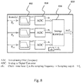
- Fig. 8 shows an acquisition device 800 in accordance with one embodiment using such conventional sampling.
- Each signal P ⁇ , Pin, Pout to be sampled is filtered using an Anti-Aliasing Filter (AAF) 802 and sampled using an Analog-to-Digital Converter (ADC) 804. Data samples are cumulated in memory 806.
- AAF Anti-Aliasing Filter
- ADC Analog-to-Digital Converter
- the signals to be sampled correspond to a given extent of the DFT of the transmission curve T(v) in the delay domain, which is independent of the scan speed vs.
- the anti-aliasing filter 802. It is a well-known and good practice to limit the bandwidth of the signal (including wideband noise and/or high-frequency spurious) before sampling. But here, care should be taken to make the filter response substantially flat over the range -f + to f + because any attenuation of the sidebands by the anti-aliasing filter 802 will result in a bias on the measured PDL. Indeed, the PDL is directly represented by the amplitude of the sidebands (relative to the mean DC part). So only 1% attenuation translates directly to roughly -1% bias. A good choice in that case may be a second-order filter which gives a flat response over a large range relative to its 3-dB cut frequency.
- the trajectory ⁇ (v) of the SOP at the output of the 2-segs of the passive SOP generator which is characterized by said complex vectorial amplitudes z l as specified in (2), only depends on two parameters, the two coupling angles ⁇ ⁇ o and ⁇ p , or equivalently the three governing Stokes vectors ⁇ o , p 0 and p 1 .
- ⁇ o is the SOP at the input of the 2-segs
- p 0 and p 1 are the PSPs of first and second segment respectively.
- Said analytical expressions of the z l given below derive from the laws of Physics.
- the specific set of equations (13) assumes that the following conditions are met:
- Fig. 9 illustrates the relationship between the governing Stokes vectors, ⁇ o , p 0 and p 1 , and the coupling angles ⁇ ⁇ 0 , ⁇ p , wherein (û 1 û 2 û 3 ) are the cartesian base vectors of the standard 3D Stokes vectors space.
- the inputs to the processing of RSB are:
- m(v n ) ⁇ , n 0..(N-1).
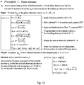
- Fig. 11 expresses the procedure (Procedure_3) of step 1002 in more details.
- the procedure involves:
- Procedure_2 the processing unit reshuffles the resulting data into a single vector of N values at sampled points n, wherein each is itself a vector whose elements are the 9 values where -4 ⁇ l ⁇ 4. This reshuffling is not fundamentaly required, but it eases the next calculations in Procedure_1 by making them faster than otherwise, as well as making this procedure very compact from a programmatic point of view.
- Fig. 12 expresses the procedure (Procedure_2) of step 1004 in more details.
- step 1006 the processing unit receives the complex transmissions derived in step 1004, or more specifically vector and computes the response vector
- the processing unit computes
- m(vn) ⁇ from vector obtained in step 1004 and known matrix defined hereinabove, for each sampled point n 0 ... (N-1)).
- Fig. 13 expresses the procedure (Procedure_1) of step 1006 in more details.
- step 1008 the processing unit computes the spectrally-varying PDL of the DUT from the response vector
- Fig. 14 expresses the procedure (Procedule_0) of step 1008 in more details.
- the input to the procedure is a vector
- m ⁇ n
- m (v n ) ⁇ of the response vector, n 0..(N-1), wherein each
- PDL value returned by Procedure_0 is expressed in dB.
- v optical frequency
- ⁇ delay (Fourier-transform conjugate variable of v) J : number of wavelength scans with fixed input-SOPs in the classic Mueller Matrix Method J : number of sidebands on one side of the Fourier transform in the resolvedsidebands method (RSB)
- T(v) power transmission curve as a function of v (v) : complex transmission associated to sideband-carrier l as a function of v, wherein ⁇ l : carrier-delay of sideband-carrier l (similar to carrier frequency but here, the carrier is characterized by its delay instead of its frequency)
- m(v) ⁇ response vector of the DUT as a function of v : equivalent matrix of RSB representing the system of equations to be solved
- z l complex vectorial amplitude of the sideband-carrier l P ⁇ (v) : phase-reference output Pin(v) : optical power of the test lightwave at the input
Landscapes
- Physics & Mathematics (AREA)
- General Physics & Mathematics (AREA)
- Optics & Photonics (AREA)
- Chemical & Material Sciences (AREA)
- Analytical Chemistry (AREA)
- Spectroscopy & Molecular Physics (AREA)
- Investigating Or Analysing Materials By Optical Means (AREA)
- Spectrometry And Color Measurement (AREA)
Applications Claiming Priority (1)
| Application Number | Priority Date | Filing Date | Title |
|---|---|---|---|
| US202063024741P | 2020-05-14 | 2020-05-14 |
Publications (2)
| Publication Number | Publication Date |
|---|---|
| EP3910310A1 true EP3910310A1 (de) | 2021-11-17 |
| EP3910310B1 EP3910310B1 (de) | 2022-10-05 |
Family
ID=75887825
Family Applications (1)
| Application Number | Title | Priority Date | Filing Date |
|---|---|---|---|
| EP21172895.1A Active EP3910310B1 (de) | 2020-05-14 | 2021-05-07 | Messung von polarisationsabhängigen verlusten |
Country Status (2)
| Country | Link |
|---|---|
| US (1) | US11644381B2 (de) |
| EP (1) | EP3910310B1 (de) |
Families Citing this family (5)
| Publication number | Priority date | Publication date | Assignee | Title |
|---|---|---|---|---|
| US10838047B2 (en) | 2018-04-17 | 2020-11-17 | Santec Corporation | Systems and methods for LIDAR scanning of an environment over a sweep of wavelengths |
| US11513228B2 (en) | 2020-03-05 | 2022-11-29 | Santec Corporation | Lidar sensing arrangements |
| US11486792B2 (en) * | 2020-06-05 | 2022-11-01 | Santec Corporation | Tunable light source for optical fiber proximity and testing |
| US12135373B2 (en) | 2021-04-16 | 2024-11-05 | santec Holdings Corporation | Systems and methods for LIDAR sensing |
| US12313883B2 (en) | 2023-03-03 | 2025-05-27 | santec Holdings Corporation | Photonic beam steering device with wavelength sweep |
Citations (3)
| Publication number | Priority date | Publication date | Assignee | Title |
|---|---|---|---|---|
| US5371597A (en) | 1993-11-23 | 1994-12-06 | At&T Corp. | System and method for measuring polarization dependent loss |
| US20040070759A1 (en) * | 2002-10-14 | 2004-04-15 | Anderson Duwayne R. | Vector representation of polarization dependent loss |
| US6856386B2 (en) | 2003-03-21 | 2005-02-15 | Thorlabs, Inc. | Single sweep polarization dependent loss measurement |
Family Cites Families (7)
| Publication number | Priority date | Publication date | Assignee | Title |
|---|---|---|---|---|
| US5298972A (en) | 1990-01-22 | 1994-03-29 | Hewlett-Packard Company | Method and apparatus for measuring polarization sensitivity of optical devices |
| US5227623A (en) | 1992-01-31 | 1993-07-13 | Hewlett-Packard Company | Method and apparatus for measuring polarization mode dispersion in optical devices |
| CA2336753C (en) | 2001-02-14 | 2007-07-03 | Itf Optical Technologies Inc.-Technologies Optiques Itf Inc. | Method for measuring polarization dependent loss and insertion loss |
| US6650406B1 (en) | 2002-09-09 | 2003-11-18 | Jds Uniphase Inc. | Polarization dependent loss measurement in photonic devices |
| US6888625B2 (en) | 2003-04-16 | 2005-05-03 | Tektronix, Inc. | Single sweep measurement of multiple optical characteristics |
| US20090141274A1 (en) | 2007-11-29 | 2009-06-04 | Bogdan Szafraniec | Polarization Dependent Loss Analyzer |
| CN102539119A (zh) | 2011-12-27 | 2012-07-04 | 上海大学 | 基于可旋转波片的Mueller矩阵测试装置和方法 |
-
2021
- 2021-05-07 EP EP21172895.1A patent/EP3910310B1/de active Active
- 2021-05-07 US US17/314,228 patent/US11644381B2/en active Active
Patent Citations (3)
| Publication number | Priority date | Publication date | Assignee | Title |
|---|---|---|---|---|
| US5371597A (en) | 1993-11-23 | 1994-12-06 | At&T Corp. | System and method for measuring polarization dependent loss |
| US20040070759A1 (en) * | 2002-10-14 | 2004-04-15 | Anderson Duwayne R. | Vector representation of polarization dependent loss |
| US6856386B2 (en) | 2003-03-21 | 2005-02-15 | Thorlabs, Inc. | Single sweep polarization dependent loss measurement |
Also Published As
| Publication number | Publication date |
|---|---|
| US20210356359A1 (en) | 2021-11-18 |
| EP3910310B1 (de) | 2022-10-05 |
| US11644381B2 (en) | 2023-05-09 |
Similar Documents
| Publication | Publication Date | Title |
|---|---|---|
| EP3910310B1 (de) | Messung von polarisationsabhängigen verlusten | |
| US6204924B1 (en) | Method and apparatus for measuring polarization mode dispersion of optical devices | |
| US6856400B1 (en) | Apparatus and method for the complete characterization of optical devices including loss, birefringence and dispersion effects | |
| JP3213104B2 (ja) | 光装置の偏光モード分散判定装置および方法 | |
| EP2397813B1 (de) | Kompensation von zeitlichen Phasenänderungen bei interferometrischen Messungen | |
| US8345238B2 (en) | Measuring optical spectral property of light based on polarization analysis | |
| US6900896B2 (en) | Method and system for measuring optical characteristics of a sub-component within a composite optical system | |
| EP1420238B1 (de) | Bestimmung einer optischen Eigenschaft unter Benutzung von überlagerten und verzögerten Signalen | |
| US7227645B2 (en) | Method and apparatus for measuring polarization mode dispersion | |
| EP1369662A2 (de) | System und Verfahren zur Entfernung der relativen Phasenungenauigkeit in einer polarimetrischen Vorrichtungscharakterisierung | |
| JPH0781888B2 (ja) | 1対のセンサ上で周囲環境の影響を遠隔的に感知する装置 | |
| US7426021B2 (en) | Interferometric optical analyzer and method for measuring the linear response of an optical component | |
| US5654793A (en) | Method and apparatus for high resolution measurement of very low levels of polarization mode dispersion (PMD) in single mode optical fibers and for calibration of PMD measuring instruments | |
| CN115266029B (zh) | 一种光器件偏振响应测量方法 | |
| US6856398B2 (en) | Method of and apparatus for making wavelength-resolved polarimetric measurements | |
| WO1996036859A1 (en) | Measurement of polarization mode dispersion | |
| US20060033927A1 (en) | Heterodyne optical spectrum analyzer | |
| US7693419B1 (en) | Optical spectrum analysis using optical interferometry | |
| EP1702203B1 (de) | Verfahren, system und einrichtung zur messung der polarisationsmodendispersion einer optischen faser | |
| CN115308483B (zh) | 一种基于机器学习的微波频率测量系统与方法 | |
| JP3998460B2 (ja) | 光学装置の特性を決定する方法及び検査装置 | |
| CA2229219A1 (en) | Method and apparatus for measuring polarization mode dispersion of optical devices | |
| US20080002972A1 (en) | All Order Polarization Mode Dispersion Compensation with Spectral Interference Based Pulse Shaping | |
| CA2236521A1 (en) | Method and apparatus for measuring polarization mode dispersion of optical devices | |
| EP4498058A1 (de) | Verfahren und vorrichtung zur einseitigen polarisationsmodendispersionsmessung |
Legal Events
| Date | Code | Title | Description |
|---|---|---|---|
| PUAI | Public reference made under article 153(3) epc to a published international application that has entered the european phase |
Free format text: ORIGINAL CODE: 0009012 |
|
| STAA | Information on the status of an ep patent application or granted ep patent |
Free format text: STATUS: THE APPLICATION HAS BEEN PUBLISHED |
|
| AK | Designated contracting states |
Kind code of ref document: A1 Designated state(s): AL AT BE BG CH CY CZ DE DK EE ES FI FR GB GR HR HU IE IS IT LI LT LU LV MC MK MT NL NO PL PT RO RS SE SI SK SM TR |
|
| B565 | Issuance of search results under rule 164(2) epc |
Effective date: 20210921 |
|
| STAA | Information on the status of an ep patent application or granted ep patent |
Free format text: STATUS: REQUEST FOR EXAMINATION WAS MADE |
|
| 17P | Request for examination filed |
Effective date: 20220119 |
|
| RBV | Designated contracting states (corrected) |
Designated state(s): AL AT BE BG CH CY CZ DE DK EE ES FI FR GB GR HR HU IE IS IT LI LT LU LV MC MK MT NL NO PL PT RO RS SE SI SK SM TR |
|
| GRAP | Despatch of communication of intention to grant a patent |
Free format text: ORIGINAL CODE: EPIDOSNIGR1 |
|
| STAA | Information on the status of an ep patent application or granted ep patent |
Free format text: STATUS: GRANT OF PATENT IS INTENDED |
|
| RIC1 | Information provided on ipc code assigned before grant |
Ipc: G01J 4/04 20060101ALI20220331BHEP Ipc: G01M 11/00 20060101AFI20220331BHEP |
|
| INTG | Intention to grant announced |
Effective date: 20220425 |
|
| GRAS | Grant fee paid |
Free format text: ORIGINAL CODE: EPIDOSNIGR3 |
|
| GRAA | (expected) grant |
Free format text: ORIGINAL CODE: 0009210 |
|
| STAA | Information on the status of an ep patent application or granted ep patent |
Free format text: STATUS: THE PATENT HAS BEEN GRANTED |
|
| AK | Designated contracting states |
Kind code of ref document: B1 Designated state(s): AL AT BE BG CH CY CZ DE DK EE ES FI FR GB GR HR HU IE IS IT LI LT LU LV MC MK MT NL NO PL PT RO RS SE SI SK SM TR |
|
| REG | Reference to a national code |
Ref country code: GB Ref legal event code: FG4D |
|
| REG | Reference to a national code |
Ref country code: CH Ref legal event code: EP |
|
| REG | Reference to a national code |
Ref country code: AT Ref legal event code: REF Ref document number: 1523012 Country of ref document: AT Kind code of ref document: T Effective date: 20221015 |
|
| REG | Reference to a national code |
Ref country code: DE Ref legal event code: R096 Ref document number: 602021000510 Country of ref document: DE |
|
| REG | Reference to a national code |
Ref country code: IE Ref legal event code: FG4D |
|
| REG | Reference to a national code |
Ref country code: LT Ref legal event code: MG9D |
|
| REG | Reference to a national code |
Ref country code: NL Ref legal event code: MP Effective date: 20221005 |
|
| REG | Reference to a national code |
Ref country code: AT Ref legal event code: MK05 Ref document number: 1523012 Country of ref document: AT Kind code of ref document: T Effective date: 20221005 |
|
| PG25 | Lapsed in a contracting state [announced via postgrant information from national office to epo] |
Ref country code: NL Free format text: LAPSE BECAUSE OF FAILURE TO SUBMIT A TRANSLATION OF THE DESCRIPTION OR TO PAY THE FEE WITHIN THE PRESCRIBED TIME-LIMIT Effective date: 20221005 |
|
| PG25 | Lapsed in a contracting state [announced via postgrant information from national office to epo] |
Ref country code: SE Free format text: LAPSE BECAUSE OF FAILURE TO SUBMIT A TRANSLATION OF THE DESCRIPTION OR TO PAY THE FEE WITHIN THE PRESCRIBED TIME-LIMIT Effective date: 20221005 Ref country code: PT Free format text: LAPSE BECAUSE OF FAILURE TO SUBMIT A TRANSLATION OF THE DESCRIPTION OR TO PAY THE FEE WITHIN THE PRESCRIBED TIME-LIMIT Effective date: 20230206 Ref country code: NO Free format text: LAPSE BECAUSE OF FAILURE TO SUBMIT A TRANSLATION OF THE DESCRIPTION OR TO PAY THE FEE WITHIN THE PRESCRIBED TIME-LIMIT Effective date: 20230105 Ref country code: LT Free format text: LAPSE BECAUSE OF FAILURE TO SUBMIT A TRANSLATION OF THE DESCRIPTION OR TO PAY THE FEE WITHIN THE PRESCRIBED TIME-LIMIT Effective date: 20221005 Ref country code: FI Free format text: LAPSE BECAUSE OF FAILURE TO SUBMIT A TRANSLATION OF THE DESCRIPTION OR TO PAY THE FEE WITHIN THE PRESCRIBED TIME-LIMIT Effective date: 20221005 Ref country code: ES Free format text: LAPSE BECAUSE OF FAILURE TO SUBMIT A TRANSLATION OF THE DESCRIPTION OR TO PAY THE FEE WITHIN THE PRESCRIBED TIME-LIMIT Effective date: 20221005 Ref country code: AT Free format text: LAPSE BECAUSE OF FAILURE TO SUBMIT A TRANSLATION OF THE DESCRIPTION OR TO PAY THE FEE WITHIN THE PRESCRIBED TIME-LIMIT Effective date: 20221005 |
|
| PG25 | Lapsed in a contracting state [announced via postgrant information from national office to epo] |
Ref country code: RS Free format text: LAPSE BECAUSE OF FAILURE TO SUBMIT A TRANSLATION OF THE DESCRIPTION OR TO PAY THE FEE WITHIN THE PRESCRIBED TIME-LIMIT Effective date: 20221005 Ref country code: PL Free format text: LAPSE BECAUSE OF FAILURE TO SUBMIT A TRANSLATION OF THE DESCRIPTION OR TO PAY THE FEE WITHIN THE PRESCRIBED TIME-LIMIT Effective date: 20221005 Ref country code: LV Free format text: LAPSE BECAUSE OF FAILURE TO SUBMIT A TRANSLATION OF THE DESCRIPTION OR TO PAY THE FEE WITHIN THE PRESCRIBED TIME-LIMIT Effective date: 20221005 Ref country code: IS Free format text: LAPSE BECAUSE OF FAILURE TO SUBMIT A TRANSLATION OF THE DESCRIPTION OR TO PAY THE FEE WITHIN THE PRESCRIBED TIME-LIMIT Effective date: 20230205 Ref country code: HR Free format text: LAPSE BECAUSE OF FAILURE TO SUBMIT A TRANSLATION OF THE DESCRIPTION OR TO PAY THE FEE WITHIN THE PRESCRIBED TIME-LIMIT Effective date: 20221005 Ref country code: GR Free format text: LAPSE BECAUSE OF FAILURE TO SUBMIT A TRANSLATION OF THE DESCRIPTION OR TO PAY THE FEE WITHIN THE PRESCRIBED TIME-LIMIT Effective date: 20230106 |
|
| P01 | Opt-out of the competence of the unified patent court (upc) registered |
Effective date: 20230513 |
|
| REG | Reference to a national code |
Ref country code: DE Ref legal event code: R097 Ref document number: 602021000510 Country of ref document: DE |
|
| PG25 | Lapsed in a contracting state [announced via postgrant information from national office to epo] |
Ref country code: SM Free format text: LAPSE BECAUSE OF FAILURE TO SUBMIT A TRANSLATION OF THE DESCRIPTION OR TO PAY THE FEE WITHIN THE PRESCRIBED TIME-LIMIT Effective date: 20221005 Ref country code: RO Free format text: LAPSE BECAUSE OF FAILURE TO SUBMIT A TRANSLATION OF THE DESCRIPTION OR TO PAY THE FEE WITHIN THE PRESCRIBED TIME-LIMIT Effective date: 20221005 Ref country code: EE Free format text: LAPSE BECAUSE OF FAILURE TO SUBMIT A TRANSLATION OF THE DESCRIPTION OR TO PAY THE FEE WITHIN THE PRESCRIBED TIME-LIMIT Effective date: 20221005 Ref country code: DK Free format text: LAPSE BECAUSE OF FAILURE TO SUBMIT A TRANSLATION OF THE DESCRIPTION OR TO PAY THE FEE WITHIN THE PRESCRIBED TIME-LIMIT Effective date: 20221005 Ref country code: CZ Free format text: LAPSE BECAUSE OF FAILURE TO SUBMIT A TRANSLATION OF THE DESCRIPTION OR TO PAY THE FEE WITHIN THE PRESCRIBED TIME-LIMIT Effective date: 20221005 |
|
| PLBE | No opposition filed within time limit |
Free format text: ORIGINAL CODE: 0009261 |
|
| STAA | Information on the status of an ep patent application or granted ep patent |
Free format text: STATUS: NO OPPOSITION FILED WITHIN TIME LIMIT |
|
| PG25 | Lapsed in a contracting state [announced via postgrant information from national office to epo] |
Ref country code: SK Free format text: LAPSE BECAUSE OF FAILURE TO SUBMIT A TRANSLATION OF THE DESCRIPTION OR TO PAY THE FEE WITHIN THE PRESCRIBED TIME-LIMIT Effective date: 20221005 Ref country code: AL Free format text: LAPSE BECAUSE OF FAILURE TO SUBMIT A TRANSLATION OF THE DESCRIPTION OR TO PAY THE FEE WITHIN THE PRESCRIBED TIME-LIMIT Effective date: 20221005 |
|
| 26N | No opposition filed |
Effective date: 20230706 |
|
| PG25 | Lapsed in a contracting state [announced via postgrant information from national office to epo] |
Ref country code: SI Free format text: LAPSE BECAUSE OF FAILURE TO SUBMIT A TRANSLATION OF THE DESCRIPTION OR TO PAY THE FEE WITHIN THE PRESCRIBED TIME-LIMIT Effective date: 20221005 |
|
| PG25 | Lapsed in a contracting state [announced via postgrant information from national office to epo] |
Ref country code: MC Free format text: LAPSE BECAUSE OF FAILURE TO SUBMIT A TRANSLATION OF THE DESCRIPTION OR TO PAY THE FEE WITHIN THE PRESCRIBED TIME-LIMIT Effective date: 20221005 |
|
| REG | Reference to a national code |
Ref country code: BE Ref legal event code: MM Effective date: 20230531 |
|
| PG25 | Lapsed in a contracting state [announced via postgrant information from national office to epo] |
Ref country code: MC Free format text: LAPSE BECAUSE OF FAILURE TO SUBMIT A TRANSLATION OF THE DESCRIPTION OR TO PAY THE FEE WITHIN THE PRESCRIBED TIME-LIMIT Effective date: 20221005 Ref country code: LU Free format text: LAPSE BECAUSE OF NON-PAYMENT OF DUE FEES Effective date: 20230507 |
|
| REG | Reference to a national code |
Ref country code: IE Ref legal event code: MM4A |
|
| PG25 | Lapsed in a contracting state [announced via postgrant information from national office to epo] |
Ref country code: IE Free format text: LAPSE BECAUSE OF NON-PAYMENT OF DUE FEES Effective date: 20230507 |
|
| PG25 | Lapsed in a contracting state [announced via postgrant information from national office to epo] |
Ref country code: IE Free format text: LAPSE BECAUSE OF NON-PAYMENT OF DUE FEES Effective date: 20230507 |
|
| PG25 | Lapsed in a contracting state [announced via postgrant information from national office to epo] |
Ref country code: IT Free format text: LAPSE BECAUSE OF FAILURE TO SUBMIT A TRANSLATION OF THE DESCRIPTION OR TO PAY THE FEE WITHIN THE PRESCRIBED TIME-LIMIT Effective date: 20221005 Ref country code: BE Free format text: LAPSE BECAUSE OF NON-PAYMENT OF DUE FEES Effective date: 20230531 |
|
| PG25 | Lapsed in a contracting state [announced via postgrant information from national office to epo] |
Ref country code: BG Free format text: LAPSE BECAUSE OF FAILURE TO SUBMIT A TRANSLATION OF THE DESCRIPTION OR TO PAY THE FEE WITHIN THE PRESCRIBED TIME-LIMIT Effective date: 20221005 |
|
| PG25 | Lapsed in a contracting state [announced via postgrant information from national office to epo] |
Ref country code: BG Free format text: LAPSE BECAUSE OF FAILURE TO SUBMIT A TRANSLATION OF THE DESCRIPTION OR TO PAY THE FEE WITHIN THE PRESCRIBED TIME-LIMIT Effective date: 20221005 |
|
| REG | Reference to a national code |
Ref country code: CH Ref legal event code: PL |
|
| PG25 | Lapsed in a contracting state [announced via postgrant information from national office to epo] |
Ref country code: CH Free format text: LAPSE BECAUSE OF NON-PAYMENT OF DUE FEES Effective date: 20240531 |
|
| PGFP | Annual fee paid to national office [announced via postgrant information from national office to epo] |
Ref country code: DE Payment date: 20250409 Year of fee payment: 5 |
|
| PGFP | Annual fee paid to national office [announced via postgrant information from national office to epo] |
Ref country code: FR Payment date: 20250409 Year of fee payment: 5 |
|
| PG25 | Lapsed in a contracting state [announced via postgrant information from national office to epo] |
Ref country code: CY Free format text: LAPSE BECAUSE OF FAILURE TO SUBMIT A TRANSLATION OF THE DESCRIPTION OR TO PAY THE FEE WITHIN THE PRESCRIBED TIME-LIMIT; INVALID AB INITIO Effective date: 20210507 |
|
| PG25 | Lapsed in a contracting state [announced via postgrant information from national office to epo] |
Ref country code: HU Free format text: LAPSE BECAUSE OF FAILURE TO SUBMIT A TRANSLATION OF THE DESCRIPTION OR TO PAY THE FEE WITHIN THE PRESCRIBED TIME-LIMIT; INVALID AB INITIO Effective date: 20210507 |
|
| PG25 | Lapsed in a contracting state [announced via postgrant information from national office to epo] |
Ref country code: TR Free format text: LAPSE BECAUSE OF FAILURE TO SUBMIT A TRANSLATION OF THE DESCRIPTION OR TO PAY THE FEE WITHIN THE PRESCRIBED TIME-LIMIT Effective date: 20221005 |
|
| PGFP | Annual fee paid to national office [announced via postgrant information from national office to epo] |
Ref country code: GB Payment date: 20260320 Year of fee payment: 6 |