EP3910995B1 - Verfahren und vorrichtung zur anzeige des messzwecks von kanalzustandsinformationen und system - Google Patents
Verfahren und vorrichtung zur anzeige des messzwecks von kanalzustandsinformationen und system Download PDFInfo
- Publication number
- EP3910995B1 EP3910995B1 EP19909578.7A EP19909578A EP3910995B1 EP 3910995 B1 EP3910995 B1 EP 3910995B1 EP 19909578 A EP19909578 A EP 19909578A EP 3910995 B1 EP3910995 B1 EP 3910995B1
- Authority
- EP
- European Patent Office
- Prior art keywords
- csi
- measurement
- csi report
- resource
- occupied
- Prior art date
- Legal status (The legal status is an assumption and is not a legal conclusion. Google has not performed a legal analysis and makes no representation as to the accuracy of the status listed.)
- Active
Links
Images




Classifications
-
- H—ELECTRICITY
- H04—ELECTRIC COMMUNICATION TECHNIQUE
- H04B—TRANSMISSION
- H04B17/00—Monitoring; Testing
- H04B17/30—Monitoring; Testing of propagation channels
- H04B17/309—Measuring or estimating channel quality parameters
-
- H—ELECTRICITY
- H04—ELECTRIC COMMUNICATION TECHNIQUE
- H04B—TRANSMISSION
- H04B7/00—Radio transmission systems, i.e. using radiation field
- H04B7/02—Diversity systems; Multi-antenna system, i.e. transmission or reception using multiple antennas
- H04B7/04—Diversity systems; Multi-antenna system, i.e. transmission or reception using multiple antennas using two or more spaced independent antennas
- H04B7/06—Diversity systems; Multi-antenna system, i.e. transmission or reception using multiple antennas using two or more spaced independent antennas at the transmitting station
- H04B7/0613—Diversity systems; Multi-antenna system, i.e. transmission or reception using multiple antennas using two or more spaced independent antennas at the transmitting station using simultaneous transmission
- H04B7/0615—Diversity systems; Multi-antenna system, i.e. transmission or reception using multiple antennas using two or more spaced independent antennas at the transmitting station using simultaneous transmission of weighted versions of same signal
- H04B7/0619—Diversity systems; Multi-antenna system, i.e. transmission or reception using multiple antennas using two or more spaced independent antennas at the transmitting station using simultaneous transmission of weighted versions of same signal using feedback from receiving side
- H04B7/0621—Feedback content
- H04B7/0626—Channel coefficients, e.g. channel state information [CSI]
-
- H—ELECTRICITY
- H04—ELECTRIC COMMUNICATION TECHNIQUE
- H04B—TRANSMISSION
- H04B7/00—Radio transmission systems, i.e. using radiation field
- H04B7/02—Diversity systems; Multi-antenna system, i.e. transmission or reception using multiple antennas
- H04B7/04—Diversity systems; Multi-antenna system, i.e. transmission or reception using multiple antennas using two or more spaced independent antennas
- H04B7/06—Diversity systems; Multi-antenna system, i.e. transmission or reception using multiple antennas using two or more spaced independent antennas at the transmitting station
- H04B7/0686—Hybrid systems, i.e. switching and simultaneous transmission
- H04B7/0695—Hybrid systems, i.e. switching and simultaneous transmission using beam selection
- H04B7/06952—Selecting one or more beams from a plurality of beams, e.g. beam training, management or sweeping
-
- H—ELECTRICITY
- H04—ELECTRIC COMMUNICATION TECHNIQUE
- H04L—TRANSMISSION OF DIGITAL INFORMATION, e.g. TELEGRAPHIC COMMUNICATION
- H04L5/00—Arrangements affording multiple use of the transmission path
- H04L5/003—Arrangements for allocating sub-channels of the transmission path
- H04L5/0048—Allocation of pilot signals, i.e. of signals known to the receiver
- H04L5/005—Allocation of pilot signals, i.e. of signals known to the receiver of common pilots, i.e. pilots destined for multiple users or terminals
-
- H—ELECTRICITY
- H04—ELECTRIC COMMUNICATION TECHNIQUE
- H04L—TRANSMISSION OF DIGITAL INFORMATION, e.g. TELEGRAPHIC COMMUNICATION
- H04L5/00—Arrangements affording multiple use of the transmission path
- H04L5/003—Arrangements for allocating sub-channels of the transmission path
- H04L5/0053—Allocation of signalling, i.e. of overhead other than pilot signals
- H04L5/0057—Physical resource allocation for CQI
-
- H—ELECTRICITY
- H04—ELECTRIC COMMUNICATION TECHNIQUE
- H04W—WIRELESS COMMUNICATION NETWORKS
- H04W24/00—Supervisory, monitoring or testing arrangements
- H04W24/08—Testing, supervising or monitoring using real traffic
-
- H—ELECTRICITY
- H04—ELECTRIC COMMUNICATION TECHNIQUE
- H04W—WIRELESS COMMUNICATION NETWORKS
- H04W24/00—Supervisory, monitoring or testing arrangements
- H04W24/10—Scheduling measurement reports ; Arrangements for measurement reports
-
- H—ELECTRICITY
- H04—ELECTRIC COMMUNICATION TECHNIQUE
- H04B—TRANSMISSION
- H04B17/00—Monitoring; Testing
- H04B17/20—Monitoring; Testing of receivers
- H04B17/24—Monitoring; Testing of receivers with feedback of measurements to the transmitter
-
- H—ELECTRICITY
- H04—ELECTRIC COMMUNICATION TECHNIQUE
- H04B—TRANSMISSION
- H04B17/00—Monitoring; Testing
- H04B17/30—Monitoring; Testing of propagation channels
- H04B17/309—Measuring or estimating channel quality parameters
- H04B17/345—Interference values
-
- H—ELECTRICITY
- H04—ELECTRIC COMMUNICATION TECHNIQUE
- H04L—TRANSMISSION OF DIGITAL INFORMATION, e.g. TELEGRAPHIC COMMUNICATION
- H04L1/00—Arrangements for detecting or preventing errors in the information received
- H04L1/004—Arrangements for detecting or preventing errors in the information received by using forward error control
- H04L1/0072—Error control for data other than payload data, e.g. control data
-
- H—ELECTRICITY
- H04—ELECTRIC COMMUNICATION TECHNIQUE
- H04L—TRANSMISSION OF DIGITAL INFORMATION, e.g. TELEGRAPHIC COMMUNICATION
- H04L5/00—Arrangements affording multiple use of the transmission path
- H04L5/0001—Arrangements for dividing the transmission path
- H04L5/0014—Three-dimensional division
- H04L5/0023—Time-frequency-space
Definitions
- This disclosure relates to the field of communications, and in particular to indicating a resource occupied for channel state information calculation.
- CSI channel state information
- a network device usually configures CSI measurement resources to allow a terminal equipment to measure CSI in corresponding resources. Furthermore, the network device needs to make the terminal equipment know calculation results of which CSI need to be fed back.
- a 5G-NR system may indicate a measurement purpose of CSI. That is, by indicating the number of CSI measurement resources corresponding to the CSI report resource, the terminal equipment may learn the measurement purpose of the CSI measurement resource, so as to perform corresponding feedback of calculation.
- FIG. 1 shows three pieces of different measurement feedback. As shown in FIG.
- a CSI report setting configuration (CSI-Report) is associated with a resource setting, for example, when the CSI-Report is associated with a channel measurement resource (CMR), the resource setting (such as a CMR) is used for layer 1 reference signal received power (L1-RSRP) channel measurement; when a CSI report setting configuration is associated with more than one resource settings, for example, the CSI-Report is associated with the CMR and a non-zero power CSI reference signal-based (NZP-CSI-RS based) interference measurement resource (IMR) (NZP-IMR for short), or the CSI-Report is associated with the CMR and a zero power CSI reference signal-based (ZP-CSI-RS based) interference measurement resource (IMR) (ZP-IMR for short), or the CSI-Report is associated with the CMR, the NZP-IMR and the ZP-IMR, a first resource setting (such as a CMR) is used for channel measurement instead of L1-RSRP
- the CSI calculation resources occupied thereby are also different.
- the calculation resources occupied by its corresponding measurement resources are unclear, which may make it impossible for the terminal equipment and network device to make an agreement on the number of occupied CSI calculation resources within a period of time, and as a result, the number of CSI measurements or calculations configured by the network device for the terminal equipment goes beyond the computing capacity of the terminal equipment, which affects the system performance.
- embodiments of this disclosure provide a method and apparatus for indicating a resource occupied for channel state information and a system.
- the network device and the terminal equipment may have a common understanding of a purpose of the same CSI measurement resource, thereby avoiding CSI measurement errors and corresponding transmission failures due to misunderstanding of the network device and the terminal equipment.
- terms “first”, and “second”, etc. are used to differentiate different elements with respect to names, and do not indicate spatial arrangement or temporal orders of these elements, and these elements should not be limited by these terms.
- Terms “and/or” include any one and all combinations of one or more relevantly listed terms.
- Terms “contain”, “include” and “have” refer to existence of stated features, elements, components, or assemblies, but do not exclude existence or addition of one or more other features, elements, components, or assemblies.
- single forms “a”, and “the”, etc. include plural forms, and should be understood as “a kind of' or “a type of' in a broad sense, but should not defined as a meaning of "one”; and the term “the” should be understood as including both a single form and a plural form, except specified otherwise.
- the term “according to” should be understood as “at least partially according to”, the term “based on” should be understood as “at least partially based on”, except specified otherwise.
- the term “communication network” or “wireless communication network” may refer to a network satisfying any one of the following communication standards: long term evolution (LTE), long term evolution-advanced (LTE-A), wideband code division multiple access (WCDMA), and high-speed packet access (HSPA), etc.
- LTE long term evolution
- LTE-A long term evolution-advanced
- WCDMA wideband code division multiple access
- HSPA high-speed packet access
- communication between devices in a communication system may be performed according to communication protocols at any stage, which may, for example, include but not limited to the following communication protocols: 1G (generation), 2G, 2.5G, 2.75G, 3G, 4G, 4.5G, and 5G and new radio (NR) in the future, etc., and/or other communication protocols that are currently known or will be developed in the future.
- 1G generation
- 2G 2.5G, 2.75G
- NR new radio
- the term "network device”, for example, refers to an equipment in a communication system that accesses a terminal equipment to the communication network and provides services for the terminal equipment.
- the network device may include but not limited to the following equipment: a base station (BS), an access point (AP), a transmission reception point (TRP), a broadcast transmitter, a mobile management entity (MME), a gateway, a server, a radio network controller (RNC), a base station controller (BSC), etc.
- the base station may include but not limited to a node B (NodeB or NB), an evolved node B (eNodeB or eNB), and a 5G base station (gNB), etc. Furthermore, it may include a remote radio head (RRH), a remote radio unit (RRU), a relay, or a low-power node (such as a femto, and a pico, etc.).
- NodeB or NB node B
- eNodeB or eNB evolved node B
- gNB 5G base station
- RRH remote radio head
- RRU remote radio unit
- relay or a low-power node (such as a femto, and a pico, etc.).
- base station may include some or all of its functions, and each base station may provide communication coverage for a specific geographical area.
- a term "cell” may refer to a base station and/or its coverage area, which may be expressed as a serving cell, and may be a macro cell or
- the term "user equipment (UE)” refers to, for example, equipment accessing to a communication network and receiving network services via a network device, and may also be referred to as "terminal equipment (TE)".
- the terminal equipment may be fixed or mobile, and may also be referred to as a mobile station (MS), a terminal, a subscriber station (SS), an access terminal (AT), or a station, etc.
- the terminal equipment may include but not limited to the following devices: a cellular phone, a personal digital assistant (PDA), a wireless modem, a wireless communication device, a hand-held device, a machine-type communication device, a lap-top, a cordless telephone, a smart cell phone, a smart watch, and a digital camera, etc.
- PDA personal digital assistant
- wireless modem a wireless communication device
- hand-held device a machine-type communication device
- a machine-type communication device a lap-top
- a cordless telephone a smart cell phone, a smart watch, and a digital camera, etc.
- the user equipment may also be a machine or a device performing monitoring or measurement.
- the user equipment may include but not limited to a machine-type communication (MTC) terminal, a vehicle mounted communication terminal, a device to device (D2D) terminal, and a machine to machine (M2M) terminal, etc.
- MTC machine-type communication
- D2D device to device
- M2M machine to machine
- FIG. 3 is a schematic diagram of a communication system of an embodiment of this disclosure, in which a case where a terminal equipment and a network device are taken as examples is schematically shown.
- a communication system 300 may include a network device 301 and a terminal equipment 302.
- the network device 301 is, for example, a network device gNB in an NR system.
- eMBB enhanced mobile broadband
- MTC massive machine type communication
- URLLC ultra-reliable and low-latency communication
- the terminal equipment 302 may transmit data to the network device 301, for example, in a grant-free transmission mode.
- the network device 301 may receive data transmitted by one or more terminal equipments 302, and feed back information (such as acknowledgement ACK/non-acknowledgement NACK) to the terminal equipment 302, and the terminal equipment 302 may acknowledge terminating a transmission process according to the feedback information, or may further perform new data transmission, or may perform data retransmission.
- FIG. 4 is a schematic diagram of the method for indicating a measurement purpose of CSI of this example. Referring to FIG. 4 , the method includes:
- the network device directly indicates a measurement purpose of a CSI measurement resource set via the above first indication information. Therefore, the terminal equipment may directly determine the measurement purpose of the CSI measurement resource set after receiving the first indication information. Thus, CSI measurement errors due to misunderstanding of the purpose of the CSI measurement resource set by the network device and the terminal equipment may be avoided.
- the above measurement purpose may be channel measurement, or interference measurement, or channel measurement and interference measurement.
- the channel measurement may be channel measurement used for beam management, or channel measurement used for CSI acquisition, or channel measurement used for time-frequency pursuit, or any combination thereof.
- the channel measurement used for beam management may include at least one of the following:
- the channel measurement used for CSI acquisition may include at least one of the following:
- Types of the channel measurement and interference measurement are not limited in this example, and reference may be made to existing standards or future-developed channel measurement or interference measurement techniques.
- At least one CSI measurement resource in the first CSI measurement resource set may be used to perform at least one of the following measurements:
- the terminal equipment may acknowledge which one or more of the above types are measurement purposes of the CSI measurement resources in the first CSI measurement resource set according to the first indication information.
- the above first CSI measurement resource set may be any one of the following:
- the terminal equipment may acknowledge measurement purposes of the reference signal resources in any one of the above sets according to the first indication information.
- the above one or more CSI measurement resource sets may be associated with a CSI report set.
- the above first CSI measurement resource set may include at least one of the following reference signal resources:
- the terminal equipment may acknowledge the measurement purposes of the reference signal resources included in the first CSI measurement resource set according to the first indication information.
- the measurement purpose of the first CSI measurement resource set may be identical to a measurement purpose of another CSI measurement resource set (referred to as a second CSI measurement resource set), and the first CSI measurement resource set is related to the second CSI measurement resource set.
- the second CSI measurement resource set may be a set of all CSI measurement resources.
- the first CSI measurement resource set may be a subset of the second CSI measurement resource set, that is, the network device indicates a measurement purpose of a part of the CSI measurement resources via the first indication information.
- the first CSI measurement resource set and the second CSI measurement resource set may be identical, that is, the network device indicates measurement purpose of all CSI measurement resources via the first indication information.
- the first CSI measurement resource set may correspond to all resources with which a CSI report is associated.
- the CSI report set with which the second CSI measurement resource set is associated and the CSI report set with which the first CSI measurement resource set is associated may be identical.
- the first indication information may indicate more flexibly.
- a CSI measurement resource set to which a CSI report set A corresponds is ⁇ A0, A1, A2, A3 ⁇ .
- the first CSI measurement resource set is A1
- the second CSI measurement resource set is ⁇ A0, A1, A2, A3 ⁇ . thus, it may be extended to indicating all or a part of resources included in the entire CSI report set A by indicating a purpose of one resource.
- the network device directly indicates the measurement purpose of the CSI measurement resource set, thereby avoiding CSI measurement errors due to misunderstanding of the measurement purpose of the CSI measurement resource set by the network device and the terminal equipment.
- the example provides a method for indicating a measurement purpose of CSI, applicable to a network device. This method is processing at a network device side corresponding to the method of Example 1, with contents identical to those in Example 1 being not going to be described herein any further.
- FIG. 5 is a schematic diagram of the method for indicating a measurement purpose of CSI of this example. As shown in FIG. 5 , the method includes:
- a manner of generating the first indication information is not limited.
- the network device directly indicates the measurement purpose of the CSI measurement resource set, thereby avoiding CSI measurement errors due to misunderstanding of the measurement purpose of the CSI measurement resource set by the network device and the terminal equipment.
- FIG. 6 is a schematic diagram of the method for indicating a measurement purpose of CSI of this example. Referring to FIG. 6 , the method includes:
- the network device indicates via the second indication information that a CSI measurement resource set (referred to as a second CSI measurement resource set) is related to one or some aspects.
- the terminal equipment may indirectly determine the measurement purpose of the CSI measurement resource set, thereby avoiding CSI measurement errors due to misunderstanding of the measurement purpose of the CSI measurement resource set by the network device and the terminal equipment.
- whether the IE is configured may be taken as a basis for determining whether the CSI measurement resource set is for beam management (such as L1-SINR or L1-RSRP or L1-RSRQ, etc.).
- an SSB itself occupies less time-frequency resources and is not suitable for being taken as a measurement purpose of CSI acquisition or time-frequency pursuit.
- the purpose of the measurement resource set may be used for beam management (L1 -SINR or L1-RSRP or L1-RSRQ etc.).
- its corresponding reported contents may indirectly indicate the purpose of the CSI measurement resource in many cases. For example, if a reported content corresponding to a CSI measurement resource is related to L1-SINR, L1 -RSRP and L1-RSRQ, the set may be used for beam management, and if the set is related to PMI, LI, CQI, and RI, etc., the set may be used for CSI acquisition.
- the measurement purpose of the second CSI measurement resource set is channel measurement for beam management.
- the above “repetition” refers to an IE in RRC signaling, which is used to configure an NZP CSI-RS measurement set.
- all NZPCSI-RS resources in the above NZP CSI-RS measurement set are transmitted by the same spatial filter, and each of the above NZPCSI-RS resources is transmitted on different OFDM symbols.
- the terminal equipment shall not assume that all CSI-RS resources in the NZP CSI-RS measurement set are transmitted by the same spatial filter.
- the terminal equipment may determine the measurement purpose of the second CSI measurement resource set according to the above relationship (for the second CSI measurement resource set, whether "repetition" is configured) indicated by the second indication information.
- the measurement purpose of the above second CSI measurement resource set is for channel measurement for beam management.
- the above CSI measurement resource set used for channel measurement including "SSB” refers to that the CSI measurement resource set only includes “SSB” resources or the CSI measurement resource set includes not only "SSB” resources but also "CSI-RS” resources.
- the SSB is a synchronization signal/physical broadcast channel (SS/PBCH) block.
- the terminal equipment may determine the measurement purpose of the second CSI measurement resource set according to the relationship indicated by the second indication information (the second CSI measurement resource set includes the "SSB").
- the second CSI measurement resource may include only CSI measurement resources, or may include CSI measurement resources and interference measurement resources related to the CSI measurement resources.
- the CSI measurement resource used for channel measurement in the second CSI measurement resource set includes at least one CSI-RS set and the CSI-RS set is configured with "repetition”
- the measurement purpose of the second CSI measurement resource set is channel measurement for beam management
- the second CSI measurement resource set includes at least one of the following: a CSI measurement resource used for channel measurement, and an interference measurement resource related to the CSI measurement resource used for channel measurement.
- the terminal equipment may determine the measurement purpose of the second CSI measurement resource set according to the relationship indicated by the above second indication information (the second CSI measurement resource set includes a CSI-RS, and the CSI-RS is configured with "repetition").
- the second CSI measurement resource set may include only CSI measurement resources used for channel measurement, or include not only the CSI measurement resources used for channel measurement, but also interference measurement resources related to the CSI measurement resources used for channel measurement.
- the report information corresponding to the CSI measurement resources used for channel measurement in the second CSI measurement resource set is related to at least one of L1-RSRP, L1-RSRQ, and an L1-SINR
- the measurement purpose of the second CSI measurement resource set is channel measurement for beam management
- the second CSI measurement resource set includes at least one of the following: CSI measurement resources used for channel measurement, and interference measurement resources related to the CSI measurement resources used for channel measurement.
- the terminal equipment may determine the measurement purpose of the second CSI measurement resource set according to the relationship indicated by the second indication information (the report information is related to at least one of L1-RSRP, L1-RSRQ and an L1-SINR).
- the second CSI measurement resource set may include only CSI measurement resources used for channel measurement, or may include not only the CSI measurement resources used for channel measurement, but also interference measurement resources related to the CSI measurement resources used for channel measurement.
- the channel measurement used for beam management may be at least one of the following: channel measurement used for L1-RSRP calculation, channel measurement used for L1-RSRQ calculation, and channel measurement used for L1-SINR calculation. Implementations of channel measurement used for beam management are not limited in this example.
- the CSI measurement resources used for channel measurement in the second CSI measurement resource set include at least one CSI-RS set and the CSI-RS set is not configured with "repetition”
- the measurement purpose of the second CSI measurement resource set is CSI acquisition or time-frequency pursuit
- the second CSI measurement resource set includes at least one of the following: CSI measurement resources used for channel measurement, and interference measurement resources related to the CSI measurement resources used for channel measurement.
- the terminal equipment may determine the measurement purpose of the second CSI measurement resource set according to the relationship indicated by the second indication information (the second CSI measurement resource set includes an CSI-RS, and the CSI-RS is not configured with "repetition").
- the second CSI measurement resource set may include only CSI measurement resources used for channel measurement, or may include not only the CSI measurement resources used for channel measurement, but also interference measurement resources related to the CSI measurement resources used for channel measurement.
- the report information corresponding to the CSI measurement resources used for channel measurement in the second CSI measurement resource set is related to at least one of a CQI, a PMI, an RI and L1
- the measurement purpose of the second CSI measurement resource set is CSI acquisition or time-frequency pursuit
- the second CSI measurement resource set includes at least one of the following: CSI measurement resources used for channel measurement, and interference measurement resources related to the CSI measurement resources used for channel measurement.
- the terminal equipment may determine the measurement purpose of the second CSI measurement resource set according to the relationship indicated by the second indication information (the report information is related to at least one of a CQI, a PMI, an RI and L1).
- the second CSI measurement resource set may include only CSI measurement resources used for channel measurement, or may include not only the CSI measurement resources used for channel measurement, but also interference measurement resources related to the CSI measurement resources used for channel measurement.
- the measurement purpose of the second CSI measurement resource set is for L1-RSRP or L1-RSRQ measurement if at least one of the following conditions is satisfied:
- the terminal equipment may determine that the measurement purpose of the second CSI measurement resource set is L1-RSRP or L1-RSRQ measurement.
- the CSI measurement resource set used for channel measurement is not used for time-frequency pursuit, that is, the CSI measurement resource set used for channel measurement is not configured with trs-info, the trs-info IE being used to indicate that all CSI-RS resources in the set have identical antenna ports.
- being only associated with the CSI measurement resources used for channel measurement refers that, being not associated with the interference measurement resources.
- the measurement purpose of the second CSI measurement resource set is L1-SINR measurement if at least one of the following conditions is satisfied:
- the terminal equipment when the terminal equipment acknowledges according to the above second indication information that at least one of the above conditions is satisfied, it may determine that the measurement purpose of the second CSI measurement resource set is L 1-SINR measurement.
- a meaning of the fifth condition is identical to that of the second condition, and shall not be described herein any further.
- a relationship between the CSI-RS or SSB and a corresponding interference measurement resource is of a quasi-colocation (QCL) type C and/or a quasi-colocation type D.
- QCL quasi-colocation
- the CSI measurement resources used for channel measurement in the second CSI measurement resource set include only CSI-RSs or include only SSBs, and a relationship between the CSI measurement resources (CSI-RSs or SSBs) and corresponding interference measurement resources is of the QCL Type-C and/or the QCL Type-D.
- FIG. 7 is a schematic diagram of the relationship between the CSI-RSs or SSBs and the corresponding interference measurement resources.
- the CSI measurement resources used for channel measurement in the second CSI measurement resource set include CSI-RSs and SSBs
- a relationship between the CSI-RSs and SSBs and corresponding interference measurement resources is of the QCL Type-C and/or the QCL Type-D.
- the CSI measurement resources used for channel measurement in the second CSI measurement resource set include not only CSI-RSs but also SSBs, the relationship between the CSI measurement resources (CSI-RSs and SSBs) and the corresponding interference measurement resources is of the QCL Type-C and/or QCL Type-D.
- FIG. 8 is a schematic diagram of the relationship between the CSI-RSs and SSBs and the corresponding interference measurement resources.
- the numbers of the CSI-RSs and SSBs may be identical, and they may one by one to correspond each other according to their orders in respective resource sets, as shown in FIG. 8 .
- the CSI measurement resource used for channel measurement in the second CSI measurement resource set and a QCL assumption of the corresponding interference measurement resources may be identical.
- their spatial filters for reception are identical. Hence, consistency of the channel measurement and the interference measurement may be ensured, and inaccurate measurement results may be avoided.
- the number of subsets of CSI measurement resources used for channel measurement in the second CSI measurement resource set and the number of subsets of corresponding interference measurement resources may be identical and sequentially correspond, as shown in FIG. 7 or 8 .
- the subsets may have only one reference signal (an SSB or a CSI-RS), or they may have multiple reference signals.
- serial numbers (#1, and #2, etc.) in FIG. 7 and FIG. 8 may refer to one or more than one reference signal resources.
- the second CSI measurement resource set is related to at least one of L1-RSRP, L1-RSRQ and an L1-SINR
- contents reported by the terminal equipment may consist of a part (CSI feedback consist of a single part). Therefore, as the reported contents of L1-RSRP, L1-RSRQ and L1-SINR need less bits, there is no need to divide them into multiple parts for performing CSI feedback. Therefore, all CSI feedback needs to be reported at a time to avoid additional overhead.
- the network device indirectly indicates the measurement purpose the CSI measurement resource set, thereby avoiding CSI measurement errors due to misunderstanding of the measurement purpose of the CSI measurement resource set by the network device and the terminal equipment.
- the example provides a method for indicating a measurement purpose of CSI, applicable to a network device. This method is processing at a network device side corresponding to the method of Example 3, with contents identical to those in Example 3 being not going to be described herein any further.
- FIG. 9 is a schematic diagram of the method for indicating a measurement purpose of CSI of this example. As shown in FIG. 9 , the method includes:
- a manner of generating the second indication information is not limited.
- the network device indirectly indicates the measurement purpose of the CSI measurement resource set, thereby avoiding CSI measurement errors due to misunderstanding of the measurement purpose of the CSI measurement resource set by the network device and the terminal equipment.
- the embodiment of this disclosure provides a method for indicating a resource occupied for CSI calculation, applicable to a terminal equipment.
- indication information from a base station is interpreted as corresponding resource occupied for CSI calculation.
- the resource occupied for CSI calculation can be different, hence, the resource occupied for CSI calculation is a representation of a measurement purpose of CSI (this embodiment is not limited thereto).
- This embodiment may also be understood as that a terminal equipment directly associates an indication of the base station with the resources occupied for CSI calculation, independent of the measurement purpose of CSI, which is hereby stated.
- the terminal equipment may determine a measurement purpose of a corresponding CSI measurement resource set. For CSI report or CSI measurement to which CSI measurement resource sets of different measurement purposes correspond, the number and duration of CSI processing units (CPUs in brief) occupied thereby are different. In this embodiment, it may also be understood as that the terminal equipment directly determines the number and duration of CPUs corresponding to the indication information after receiving the above indication information (the first indication information or second indication information).
- the conditions associated with a first CSI report set include:
- the terminal equipment determines the time T and the number K of the CPUs occupied by the CSI report or the CSI measurement to which the first CSI report set corresponds according to the conditions associated with the first CSI report set indicated by the third indication information.
- the number K of the CPUs occupied by the CSI report or the CSI measurement to which the first CSI report set corresponds may be at least one of the following: 0; 1; 2; K s ; and N CPU .
- K s may be at least one of the following: the number of SSB resources, the number of CSI-RS resources, a maximum value of the number of CSI-RS resources and the number of SSB resources, and a sum of the number of CSI-RS resources and the number of SSB resources.
- K s is the number of SSB resources; if the CSI channel measurement resource set with which the first CSI report set is associated only includes CSI-RSs, K s is the number of CSI-RS resources; and if the CSI channel measurement resource set with which the first CSI report set is associated includes CSI-RSs and SSBs, K s is a maximum value of the number of CSI-RS resources and the number of SSB resources, or K s is the sum of the number of CSI-RS resources and the number of SSB resources.
- the above N CPU is the number of parallel CPUs supported by the terminal equipment.
- the terminal equipment may report its parallel CSI calculation capability N CPU to the network side according to its own capabilities.
- N CPU refers to the number of CSI processing units (CPUs) used by terminal equipment in CSI report processing in all configured cells. If L CPUs on a given OFDM symbol are occupied to calculate the CSI report, it is deemed that the terminal equipment has N CPU -L unoccupied CPUs.
- the terminal equipment needs not to report measurement results of N-M pieces of CSI of lowest priorities.
- a time T of a CPU occupied by CSI report corresponding to the first CSI report set may be at least one of the following: for example, if the CSI report is aperiodic CSI report, time T of the CPU occupied by the CSI report is: from a first or a last symbol after downlink control information (PDCCH) triggering the CSI report to a first or a last symbol of an uplink shared channel (PUSCH) or an uplink control channel (PUCCH) carrying the CSI report.
- PDCCH downlink control information
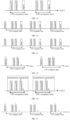
- FIG. 11 shows an example of a time T of a CPU occupied by CSI report in a case of aperiodic CSI report.
- the time T is from a first symbol after a PDCCH triggering the CSI report to a last symbol of a PUCCH/PUSCH carrying the CSI report.
- time T of the CPU occupied by the CSI report is: from a first or a last symbol of a CSI measurement occasion related to the CSI report to a first or a last symbol of an uplink shared channel (PUSCH) or an uplink control channel (PUCCH) carrying the CSI report.
- PUSCH uplink shared channel
- PUCCH uplink control channel
- CSI measurement resources to which the above CSI measurement occasion corresponds may be channel measurement resources or interference measurement resources (if there exist interference measurement resources).
- they may be CSI-RS resources, or CSI-IM resources, or SSB resources.
- FIG. 12 shows an example of a time T of a CPU occupied by CSI report in a case of periodic CSI report.
- the time T is from a first symbol of a CSI measurement occasion to a last symbol of a PUCCH or PUSCH carrying the CSI report.
- the time T of the CPU occupied by the CSI report is: from a first or a last symbol after the downlink control information (PDCCH) triggering the CSI report to a first or a last symbol of the uplink shared channel (PUSCH) carrying the CSI report.
- PUSCH uplink shared channel
- FIG. 13 shows an example of a time T of a CPU occupied by CSI report in a case of semi-persistent CSI report triggered by a PDCCH.
- the time T is from a first symbol after the PDCCH triggering the CSI report to a last symbol of a PUSCH carrying the CSI report.
- the time T of the CPU occupied by the CSI report is: from a first or a last symbol of a CSI measurement occasion related to the CSI report to a first or a last symbol of an uplink shared channel (PUSCH) carrying the CSI report. Meanings of the CSI measurement occasion and CSI measurement resources to which the CSI measurement occasion corresponds are identical to those described above, and shall not be described herein any further.
- the time (T) of CPUs occupied by CSI measurement to which the first CSI report set corresponds may be at least one of the following.
- the time (T) of CPUs occupied by the CSI measurement to which the CSI report set corresponds is: from a first or a last symbol after the downlink control information (PDCCH) triggering the CSI report set to a maximum value of x+Z 0 and y+Z 1 .
- PDCCH downlink control information
- the above Z 1 is related to an ability of the terminal equipment to report to the network side.
- the ability refers to that the terminal equipment reports different report processing times related to the CSI calculation for beam management to the network side according to different subcarrier spacings.
- the processing times related to the CSI calculation for beam management may refer to being related a calculation purpose (L1-RSRP, L1-SINR, L1-RSRQ) corresponding to the above CSI report set.
- the above channel measurement resources or interference measurement resources may be used for L1-SINR measurement, for example, they may be one of a CSI-RS, an SSB, and a CSI-IM. Furthermore, periods of the above channel measurement resources and interference measurement resources (if there exist interference measurement resources) used for the L1-SINR measurement may be identical. An advantage that the periods of these resources are identical is that fairness and accuracy of results of joint estimation by channel measurement and interference measurement may be ensured.
- FIG. 15 shows two examples of a time T of a CPU occupied by corresponding CSI measurement in a case where a CSI report set is aperiodic.
- x+Z 0 ⁇ y+Z 1
- the time T of the CPU occupied by the corresponding CSI measurement is a first symbol after a PDCCH triggering the CSI report to y+Z 1
- x+Z 0 >y+Z 1
- the time T of the CPU occupied by the corresponding CSI measurement is a first symbol after a PDCCH triggering the CSI report to x+Z 0 .
- the time (T) of the CPU occupied by the CSI measurement corresponding to the CSI report set is: from a first symbol of an earliest measurement occasion in measurement occasions of the CSI measurement resources associated with the CSI report set in a transmission occasion associated with the CSI report set to y'+Z 1 .
- Z 1 is identical to what is described above
- y' is a last symbol of a latest measurement occasion in transmission occasions of the CSI measurement resources related to the CSI report set in the above transmission occasions.
- the above CSI measurement resources may be resources used for CSI channel measurement, and may also be resources used for interference measurement.
- FIG. 16 shows an example of a time T of a CPU occupied by CSI measurement in a case where a CSI report set is periodic.
- the CPU occupancy time is from resource #1 to resource #3+Z 1
- resource #1 is (the first symbol of) the above earliest measurement occasion
- resource #3 is (the first or last symbol of) the above latest measurement occasion.
- the time domain behavior corresponding to the above CSI report set is semi-persistent, and initial CSI measurement corresponding to the CSI report set is triggered by downlink control information (PDCCH), for the CSI measurement, the time (T) of the CPU it occupies is from a first symbol after the downlink control information (PDCCH) triggering the CSI report set to a maximum value of x+Z 0 and y+Z 1 . Meanings of x, Z 0 , y and Z 1 are identical to what is described above.
- FIGs. 17 and 18 show two examples of a time T occupied by CSI measurement corresponding to the CSI report set in a case of a semi-persistent CSI report set triggered by a PDCCH.
- the time T of the CPU occupied by the CSI measurement is a first symbol after the PDCCH triggering the CSI measurement to y+Z 1 ; and in the example in FIG. 18 , x+Z 0 >y+Z 1 , the time T of the CPU occupied by the CSI measurement is a first symbol after the PDCCH triggering the CSI report to x+Z 0 .
- a time (T) of a CPU occupied by CSI measurement to which the CSI report corresponds other than CSI measurement initially triggered by a PDCCH is: from a first symbol of an earliest measurement occasion in measurement occasions of the CSI measurement resources related to the CSI report set to y'+Z 1 . Meanings of y' and Z 1 are identical to what is described above.
- the above CSI measurement resources may be resources used for CSI channel measurement, and may also be resources used for interference measurement.
- FIG. 19 shows an example of a time T of a CPU occupied by CSI measurement to which a CSI report set corresponds in a case of semi-persistent CSI report triggered by an MAC-CE.
- the CPU occupancy time T is from resource #1 to resource #2+Z 1
- resource #1 is (the first symbol of) the above earliest measurement occasion
- resource #2 is (the first symbol of) the above latest measurement occasion.
- the CPU occupancy time T for each of other transmission occasions than the transmission occasion (a first transmission occasion) to which related CSI measurement initially triggered by a PDCCH corresponds is from resource #1 to resource #2+Z 1 , resource #1 is (the first symbol of) the earliest transmission occasion in the other transmission occasions, and resource #2 is (the last symbol of) the latest measurement occasion in the other transmission occasions.
- the terminal equipment receives signaling (such as RRC signaling) from a network device.
- the signaling indicates that the above CSI report set needs to perform CSI report and a content of the CSI report is related to L1-SINR measurement, then the CSI report to which the CSI report set corresponds occupies K CPUs, and a corresponding occupancy time is the occupancy time T in the case where the terminal equipment needs to perform CSI report described above, examples of which being as shown in FIGs. 11-14 .
- the terminal equipment receives signaling (such as RRC signaling) from the network device.
- the signaling indicates that the above CSI report set need not to perform CSI report, and a channel measurement set to which the CSI report set corresponds is not used for time-frequency pursuit ("trs-info" is not configured), and the CSI measurement resource set with which the CSI report set is associated includes only a channel measurement resource set (not including an interference measurement resource set), then the CSI measurement to which the CSI report set corresponds occupies K CPUs, and a corresponding occupancy time is the occupancy time T in the case where the terminal equipment does not need to perform CSI report described above, examples of which being as shown in FIGs. 15-19 .
- the terminal equipment receives signaling (such as RRC signaling) from the network device.
- the signaling indicates that the above CSI report set need not to perform CSI report, and a channel measurement set to which the CSI report set corresponds is not used for time-frequency pursuit ("trs-info" is not configured), and the CSI measurement resource set with which the CSI report set is associated includes not only a channel measurement resource set but also an interference measurement resource set, then the CSI measurement to which the CSI report set corresponds occupies K CPUs, and a corresponding occupancy time is the occupancy time T in the case where the terminal equipment does not need to perform CSI report described above, examples of which being as shown in FIGs. 15-19 .
- the terminal equipment receives signaling (such as RRC signaling) from the network device.
- the signaling indicates that the above CSI report set needs to perform CSI report and a channel measurement set to which the CSI report set corresponds is configured with "repetition", then the CSI report to which the CSI report set corresponds occupies K CPUs, and a corresponding occupancy time is the occupancy time T in the case where the terminal equipment needs to perform CSI report described above, examples of which being as shown in FIGs. 11-14 .
- the terminal equipment receives signaling (such as RRC signaling) from the network device.
- the signaling indicates that the above CSI report set does not need to perform CSI report and a channel measurement set to which the CSI report set corresponds is configured with "repetition", then the CSI measurement to which the CSI report set corresponds occupies K CPUs, and a corresponding occupancy time is the occupancy time T in the case where the terminal equipment does not need to perform CSI report described above, examples of which being as shown in FIGs. 15-19 .
- the terminal equipment receives signaling (such as RRC signaling) from the network device.
- the signaling indicates that the above CSI report set needs to perform CSI report and a channel measurement set to which the CSI report set corresponds is not configured with "repetition” and is not used for time-frequency pursuit ("trs-info" is not configured), then the CSI report to which the CSI report set corresponds occupies K CPUs, and a corresponding occupancy time is the occupancy time T in the case where the terminal equipment needs to perform CSI report described above, examples of which being as shown in FIGs. 11-14 .
- the terminal equipment receives signaling (such as RRC signaling) from the network device.
- the signaling indicates that the above CSI report set does not need to perform CSI report and a channel measurement set to which the CSI report set corresponds is not configured with "repetition” and is not used for time-frequency pursuit ("trs-info" is not configured), then the CSI measurement to which the CSI report set corresponds occupies K CPUs, and a corresponding occupancy time is the occupancy time T in the case where the terminal equipment does not need to perform CSI report described above, examples of which being as shown in FIGs. 15-19 .
- the network device indicates the conditions related to the CSI measurement resource set, thereby avoiding CSI measurement errors due to misunderstanding of the measurement purpose of the CSI measurement resource set by the network device and the terminal equipment.
- the embodiment provides a method for indicating a resource occupied for CSI calculation, applicable to a network device. This method is processing at a network device side corresponding to the method of Embodiment 5, with contents identical to those in Embodiment 5 being not going to be described herein any further.
- FIG. 20 is a schematic diagram of the method for indicating a resource occupied for CSI calculation of this embodiment. As shown in FIG. 20 , the method includes:
- a manner of generating the third indication information is not limited.
- the network device indicates the conditions related to the CSI measurement resource set, thereby avoiding CSI measurement errors due to misunderstanding of the measurement purpose of the CSI measurement resource set by the network device and the terminal equipment.
- This example provides an apparatus for indicating a measurement purpose of channel state information, configured in a terminal equipment.
- principles of the apparatus for solving problems are similar to that of the method in Example 1, reference may be made to the implementation of the method in Example 1 for implementation of this apparatus, with identical contents being not going to be described herein any further.
- FIG. 21 is a schematic diagram of an apparatus 2100 for indicating a measurement purpose of CSI of this example. As shown in FIG. 21 , the apparatus 2100 includes:
- the network device indicates directly the measurement purpose of the CSI measurement resource set, thereby avoiding CSI measurement errors due to misunderstanding of the measurement purpose of the CSI measurement resource set by the network device and the terminal equipment.
- This example provides an apparatus for indicating a measurement purpose of CSI, configured in a network device.
- the apparatus for solving problems are similar to that of the method in Example 2, reference may be made to the implementation of the method in Example 2 for implementation of this apparatus, with identical contents being not going to be described herein any further.
- FIG. 22 is a schematic diagram of an apparatus 2200 for indicating a measurement purpose of CSI of this example. As shown in FIG. 22 , the apparatus 2200 includes:
- the network device directly indicates the measurement purpose of the CSI measurement resource set, thereby avoiding CSI measurement errors due to misunderstanding of the measurement purpose of the CSI measurement resource set by the network device and the terminal equipment.
- This example provides an apparatus for indicating a measurement purpose of CSI, configured in a terminal equipment.
- principles of the apparatus for solving problems are similar to that of the method in Example 3, reference may be made to the implementation of the method in Example 3 for implementation of this apparatus, with identical contents being not going to be described herein any further.
- FIG. 23 is a schematic diagram of an apparatus 2300 for indicating a measurement purpose of CSI of this example. As shown in FIG. 23 , the apparatus 2300 includes:
- the network device indirectly indicates the measurement purpose of the CSI measurement resource set, thereby avoiding CSI measurement errors due to misunderstanding of the measurement purpose of the CSI measurement resource set by the network device and the terminal equipment.
- This example provides an apparatus for indicating a measurement purpose of CSI, configured in a network device.
- principles of the apparatus for solving problems are similar to that of the method in Example 4, reference may be made to the implementation of the method in Example 4 for implementation of this apparatus, with identical contents being not going to be described herein any further.
- FIG. 24 is a schematic diagram of an apparatus 2400 for indicating a measurement purpose of CSI of this example. As shown in FIG. 24 , the apparatus 2400 includes:
- the network device indirectly indicates the measurement purpose of the CSI measurement resource set, thereby avoiding CSI measurement errors due to misunderstanding of the measurement purpose of the CSI measurement resource set by the network device and the terminal equipment.
- This embodiment provides an apparatus for indicating a resource occupied for CSI calculation, configured in a terminal equipment.
- an apparatus for indicating a resource occupied for CSI calculation configured in a terminal equipment.
- FIG. 25 is a schematic diagram of an apparatus 2500 for indicating a resource occupied for CSI calculation of this embodiment. As shown in FIG. 25 , the apparatus 2500 includes:
- the network device indicates the conditions related to the CSI measurement resource set, thereby avoiding CSI measurement errors due to misunderstanding of the measurement purpose of the CSI measurement resource set by the network device and the terminal equipment.
- This embodiment provides an apparatus for indicating a resource occupied for CSI calculation, configured in a network device.
- principles of the apparatus for solving problems are similar to that of the method in Embodiment 6, reference may be made to the implementation of the method in Embodiment 6 for implementation of this apparatus, with identical contents being not going to be described herein any further.
- FIG. 26 is a schematic diagram of an apparatus 2600 for indicating a resource occupied for CSI calculation of this embodiment. As shown in FIG. 26 , the apparatus 2600 includes:
- the network device indicates the conditions related to the CSI measurement resource set, thereby avoiding CSI measurement errors due to misunderstanding of the measurement purpose of the CSI measurement resource set by the network device and the terminal equipment.
- This embodiment provides a terminal equipment, including the apparatus described in Example 3 or 7 or Embodiment 11.
- FIG. 27 is a schematic diagram of the terminal equipment of the embodiment of this disclosure.
- a terminal equipment 2700 may include a central processing unit 2701 and a memory 2702, the memory 2702 being coupled to the central processing unit 2701.
- this figure is illustrative only, and other types of structures may also be used, so as to supplement or replace this structure and achieve a telecommunications function or other functions.
- the functions of the apparatus described in Example 3 or 7 or Embodiment 11 may be integrated into the central processing unit 2701, and the central processing unit 2701 achieves the functions of the apparatus described in Example 3 or 7 or Embodiment 11.
- the functions of the apparatus described in Example 3 or 7 or Embodiment 11 are incorporated herein, and shall not be described herein any further.
- the apparatus described in Example 3 or 7 or Embodiment 11 and the central processing unit 2701 may be configured separately; for example, the apparatus described in Example 3 or 7 or Embodiment 11 may be configured as a chip connected to the central processing unit 2701, and the functions of the apparatus described in Example 3 or 7 or Embodiment 11 are executed under control of the central processing unit 2701.
- the terminal equipment 2700 may further include a communication module 2703, an input unit 2704, an audio processing unit 2705, a display 2706, and a power supply 2707, etc. It should be noted that the terminal equipment 2700 does not necessarily include all the parts shown in FIG. 27 . Furthermore, the terminal equipment 2700 may include parts not shown in FIG. 27 , and the related art may be referred to.
- the central processing unit 2701 is sometimes referred to as a controller or an operational control, which may include a microprocessor or other processor devices and/or logic devices.
- the central processing unit 2701 receives input and controls operations of components of the terminal equipment 2700.
- the memory 2702 may be, for example, one or more of a buffer memory, a flash memory, a hard drive, a mobile medium, a volatile memory, a nonvolatile memory, or other suitable devices, which may store various data, etc., and furthermore, store programs executing related information. And the central processing unit 2701 may execute programs stored in the memory 2702, so as to realize information storage or processing, etc. Functions of other parts are similar to those of the related art, which shall not be described herein any further.
- the parts of the terminal equipment 2700 may be realized by specific hardware, firmware, software, or any combination thereof, without departing from the scope of this disclosure.
- the embodiment of this disclosure provides a network device, including the apparatus described in Example 4 or 8 or Embodiment 12.
- FIG. 28 is a schematic diagram of a structure of one implementation of the network device of the embodiment of this disclosure.
- a network device 2800 may include a central processing unit (CPU) 2801 and a memory 2802, the memory 2802 being coupled to the central processing unit 2801.
- the memory 2802 may store various data, and furthermore, it may store a program for data processing, and execute the program under control of the central processing unit 2801, so as to receive various information transmitted by a terminal equipment, and transmit various information to the terminal equipment.
- the functions of the apparatus described in Example 4 or 8 or Embodiment 12 may be integrated into the central processing unit 2801, and the central processing unit 2801 achieves the functions of the apparatus described in Example 4 or 8 or Embodiment 12.
- the functions of the apparatus described in Example 4 or 8 or Embodiment 12 are incorporated herein, and shall not be described herein any further.
- the apparatus described in Example 4 or 8 or Embodiment 12 and the central processing unit 2801 may be configured separately; for example, the apparatus described in Example 4 or 8 or Embodiment 12 may be configured as a chip connected to the central processing unit 2801, and the functions of the apparatus described in Example 4 or 8 or Embodiment 12 are executed under control of the central processing unit 2801.
- the network device 2800 may include a transceiver 2803, and an antenna 2804, etc. Functions of the above components are similar to those in the related art, and shall not be described herein any further. It should be noted that the network device 2800 does not necessarily include all the parts shown in FIG. 28 . Furthermore, the network device 2800 may include parts not shown in FIG. 28 , and the related art may be referred to.
- the embodiment of this disclosure provides a communication system, including a network device and a terminal equipment.
- the network device is, for example, the network device 2800 described in Embodiment 14
- the terminal equipment is, for example, the terminal equipment 2700 described in Embodiment 13.
- the terminal equipment is, for example, a UE served by a gNB, and may include conventional compositions and functions of a terminal equipment in addition to the functions of the apparatus described in Example 3 or 7 or Embodiment 11, which are as described in Embodiment 13, and shall not be described herein any further.
- the network device may be, for example, a gNB in NR, and may include conventional compositions and functions of a network device in addition to the functions of the apparatus described in Example 4 or 8 or Embodiment 12, which are as described in Embodiment 14, and shall not be described herein any further.
- An embodiment of this disclosure provides a computer readable program, which, when executed in a terminal equipment, will cause a computer to carry out the method described in Example 1 or 9 or Embodiment 5 in the terminal equipment.
- An embodiment of this disclosure provides a storage medium storing a computer readable program, which will cause a computer to carry out the method described in Example 1 or 9 or Embodiment 5 in a terminal equipment.
- An embodiment of this disclosure provides a computer readable program, which, when executed in a network device, will cause a computer to carry out the method described in Example 2 or 10 or Embodiment 6 in the network device.
- An embodiment of this disclosure provides a storage medium storing a computer readable program code, which will cause a computer to carry out the method described in Example 2 or 10 or Embodiment 6 in a network device.
- the above apparatuses and methods of this disclosure may be implemented by hardware, or by hardware in combination with software.
- This disclosure relates to such a computer-readable program that when the program is executed by a logic device, the logic device is enabled to carry out the apparatus or components as described above, or to carry out the methods or steps as described above.
- the present disclosure also relates to a storage medium for storing the above program, such as a hard disk, a floppy disk, a CD, a DVD, and a flash memory, etc.
- the methods/apparatuses described with reference to the embodiments of this disclosure may be directly embodied as hardware, software modules executed by a processor, or a combination thereof.
- one or more functional block diagrams and/or one or more combinations of the functional block diagrams shown in the drawings may either correspond to software modules of procedures of a computer program, or correspond to hardware modules.
- Such software modules may respectively correspond to the steps shown in the drawings.
- the hardware module for example, may be carried out by firming the soft modules by using a field programmable gate array (FPGA).
- FPGA field programmable gate array
- the soft modules may be located in an RAM, a flash memory, an ROM, an EPROM, and EEPROM, a register, a hard disc, a floppy disc, a CD-ROM, or any memory medium in other forms known in the art.
- a memory medium may be coupled to a processor, so that the processor may be able to read information from the memory medium, and write information into the memory medium; or the memory medium may be a component of the processor.
- the processor and the memory medium may be located in an ASIC.
- the soft modules may be stored in a memory of a mobile terminal, and may also be stored in a memory card of a pluggable mobile terminal.
- the soft modules may be stored in the MEGA-SIM card or the flash memory device of a large capacity.
- One or more functional blocks and/or one or more combinations of the functional blocks in the drawings may be realized as a universal processor, a digital signal processor (DSP), an application-specific integrated circuit (ASIC), a field programmable gate array (FPGA) or other programmable logic devices, discrete gate or transistor logic devices, discrete hardware component or any appropriate combinations thereof carrying out the functions described in this application.
- DSP digital signal processor
- ASIC application-specific integrated circuit
- FPGA field programmable gate array
- the one or more functional block diagrams and/or one or more combinations of the functional block diagrams in the drawings may also be realized as a combination of computing equipment, such as a combination of a DSP and a microprocessor, multiple processors, one or more microprocessors in communication combination with a DSP, or any other such configuration.
Landscapes
- Engineering & Computer Science (AREA)
- Signal Processing (AREA)
- Computer Networks & Wireless Communication (AREA)
- Physics & Mathematics (AREA)
- Electromagnetism (AREA)
- Quality & Reliability (AREA)
- Mobile Radio Communication Systems (AREA)
Claims (9)
- In einem Endgerät (2700) konfigurierte Einrichtung (2500) zum Anzeigen einer Ressource, die für eine Berechnung von Kanalzustandsinformationen belegt ist, wobei die Einrichtung Folgendes umfasst:
eine Empfangseinheit (2501), die dazu konfiguriert ist, von einer Netzwerkvorrichtung (2800) übertragene Anzeigeinformationen zu empfangen, wobei die Anzeigeinformationen anzeigen, dass der erste CSI-Berichtssatz einen CSI-Bericht durchführen muss und ein Inhalt des CSI-Berichts auf LL-SINR bezogen ist, und die Anzeigeinformationen ferner mindestens eine der folgenden einem ersten CSI-Berichtssatz zugeordneten Bedingungen anzeigen, dass:ein dem ersten CSI-Berichtssatz zugeordneter CSI-Messressourcensatz nur (eine) Kanalmessressource(n) umfasst; undein dem ersten CSI-Berichtssatz zugeordneter CSI-Messressourcensatz (eine) Kanalmessressource(n) und (eine) Störungsmessressource(n) umfasst; undeine Bestimmungseinheit (2502), die dazu konfiguriert ist, eine Zeit, T und eine Anzahl, K, von CSI-Verarbeitungseinheiten, CPUs, die durch einen CSI-Bericht oder eine CSI-Messung belegt ist, dem/der der erste CSI-Berichtssatz entspricht, gemäß den Anzeigeinformationen zu bestimmen, wobei die Anzahl, K, von CSI-Verarbeitungseinheiten, die durch einen CSI-Bericht oder eine CSI-Messung belegt ist, dem/der der erste CSI-Berichtssatz entspricht, 1 ist. - Vorrichtung (2500) nach Anspruch 1, wobei die Zeit, T, von CSI-Verarbeitungseinheiten, CPUs, die durch einen CSI-Bericht belegt ist, dem der erste CSI-Berichtssatz entspricht, mindestens einer der Folgenden entspricht, wenn das Endgerät (2700) einen CSI-Bericht durchführen muss:wenn der CSI-Bericht ein aperiodischer CSI-Bericht ist, ist die Zeit, T, von CSI-Verarbeitungseinheiten, CPUs, die durch den CSI-Bericht belegt ist: von einem ersten oder einem letzten Symbol nach Downlink-Steuerinformationen, die den CSI-Bericht auslösen, bis zu einem ersten oder einem letzten Symbol eines gemeinsam genutzten Uplink-Kanals oder eines den CSI-Bericht tragenden Uplink-Steuerkanals;wenn der CSI-Bericht ein periodischer CSI-Bericht ist, ist die Zeit, T, von CSI-Verarbeitungseinheiten, CPUs, die durch den CSI-Bericht belegt ist: von einem ersten oder einem letzten Symbol einer auf den CSI-Bericht bezogenen CSI-Messgelegenheit bis zu einem ersten oder einem letzten Symbol eines gemeinsam genutzten Uplink-Kanals oder eines den CSI-Bericht tragenden Uplink-Steuerkanals;wenn der CSI-Bericht ein von einem gemeinsam genutzten Uplink-Kanal getragener semipersistierender CSI-Bericht ist und anfänglich durch Downlink-Steuerinformationen ausgelöst ist, ist die Zeit, T, von CSI-Verarbeitungseinheiten, CPUs, die durch den CSI-Bericht belegt ist: von einem ersten oder einem letzten Symbol nach den Downlink-Steuerinformationen, die den CSI-Bericht auslösen, bis zu einem ersten oder einem letzten Symbol des gemeinsam genutzten den CSI-Bericht tragenden Uplink-Kanals; undwenn der CSI-Bericht ein von einem gemeinsam genutzten Uplink-Kanal getragener semipersistierender CSI-Bericht ist und anfänglich nicht durch Downlink-Steuerinformationen ausgelöst ist, ist die Zeit, T, von CSI-Verarbeitungseinheiten, CPUs, die durch den CSI-Bericht belegt ist: von einem ersten oder einem letzten Symbol einer auf den CSI-Bericht bezogenen CSI-Messgelegenheit bis zu einem ersten oder einem letzten Symbol des gemeinsam genutzten den CSI-Bericht tragenden Uplink-Kanals.
- Vorrichtung (2500) nach Anspruch 1, wobei die Zeit, T, von CSI-Verarbeitungseinheiten, CPUs, die durch eine CSI-Messung belegt ist, der der erste CSI-Berichtssatz entspricht, mindestens eine der Folgenden entspricht, wenn das Endgerät (2700) keinen CSI-Bericht durchführen muss:wenn ein Zeitdomäneverhalten, dem der CSI-Berichtssatz entspricht, aperiodisch ist, ist die Zeit, T, von CSI-Verarbeitungseinheiten, CPUs, die durch die CSI-Messung belegt ist, der der CSI-Berichtssatz entspricht: von einem ersten oder einem letzten Symbol nach den Downlink-Steuerinformationen, die den CSI-Berichtssatz auslösen, bis zu einem Maximalwert von x + Z0 und y + Z1;wenn ein Zeitdomäneverhalten, dem der CSI-Berichtssatz entspricht, periodisch ist, ist die Zeit, T, von CSI-Verarbeitungseinheiten, CPUs, die durch die CSI-Messung belegt ist, der der CSI-Berichtssatz entspricht: von einem ersten Symbol einer früheren Messgelegenheit unter Messgelegenheiten der auf den CSI-Berichtssatz bezogenen CSI-Messressource in einer auf den CSI-Berichtssatz bezogenen Übertragungsgelegenheit bis y' + Z1;wenn ein Zeitdomäneverhalten, dem der CSI-Berichtssatz entspricht, semipersistierend ist und eine anfängliche CSI-Ressourcenmessung, der der CSI-Berichtssatz entspricht, durch Downlink-Steuerinformationen für die anfängliche CSI-Ressourcenmessung ausgelöst ist, ist die Zeit, T, von CSI-Verarbeitungseinheiten, CPUs, die durch die CSI-Messung belegt ist, der der CSI-Berichtssatz entspricht: von einem ersten Symbol nach den Downlink-Steuerinformationen, die den CSI-Berichtssatz auslösen, bis zu einem Maximalwert von x + Z0 und y + Z1;wenn ein Zeitdomäneverhalten, dem der CSI-Berichtssatz entspricht, semipersistierend ist, aber eine anfängliche CSI-Ressourcenmessung, der der CSI-Berichtssatz entspricht, nicht durch Downlink-Steuerinformationen ausgelöst ist, ist die Zeit, T, von CSI-Verarbeitungseinheiten, CPUs, die durch die CSI-Messung belegt ist, der der CSI-Berichtssatz entspricht: von einem ersten Symbol einer früheren Messgelegenheit unter Messgelegenheiten der auf den CSI-Berichtssatz bezogenen CSI-Messressource bis y' + Z1; undwenn ein Zeitdomäneverhalten, dem der CSI-Berichtssatz entspricht, semipersistierend ist und eine anfängliche CSI-Ressourcenmessung, der der CSI-Berichtssatz entspricht, durch Downlink-Steuerinformationen ausgelöst ist, ist die Zeit, T, von CSI-Verarbeitungseinheiten, CPUs, die durch die CSI-Messung belegt ist, der der CSI-Berichtssatz entspricht, bei anderen CSI-Ressourcemessungen abgesehen von der anfängliche CSI-Ressourcenmessung: von einem ersten Symbol einer früheren Messgelegenheit unter Messgelegenheiten der auf den CSI-Berichtssatz bezogenen CSI-Messressource bis y' + Z1;wobei x das erste oder das letzte Symbol nach den Downlink-Steuerinformationen ist, die den CSI-Berichtssatz auslöst, y ein letztes Symbol einer letzten auf den CSI-Berichtssatz bezogenen CSI-Kanalmessressource oder Störungsmessressource ist, y' ein erstes Symbol einer letzten Messgelegenheit in Übertragungsgelegenheit der auf den CSI-Berichtssatz bezogenen CSI-Messressource in den Übertragungsgelegenheiten ist, Z0 ein CSI-Berechnungszeitpunkt ist, der auf eine CSI-Messung oder einen durch Steuerinformationen ausgelösten Bericht bezogen ist, und Z1 ein auf die CSI-Messressource bezogener CSI-Berechnungszeitpunkt ist.
- Verfahren zum Anzeigen einer Ressource, die für eine von einem Endgerät (2700) durchgeführte Berechnung von Kanalzustandsinformationen belegt ist, wobei das Verfahren Folgendes umfasst:
Empfangen (1001) von von einer Netzwerkvorrichtung (2800) übertragenen Anzeigeinformationen, wobei die Anzeigeinformationen anzeigen, dass der erste CSI-Berichtssatz einen CSI-Bericht durchführen muss und ein Inhalt des CSI-Berichts auf LL-SINR bezogen ist, und die Anzeigeinformationen ferner mindestens eine der folgenden einem ersten CSI-Berichtssatz zugeordneten Bedingungen anzeigen, dass:ein dem ersten CSI-Berichtssatz zugeordneter CSI-Messressourcensatz nur eine Kanalmessressource umfasst; undein dem ersten CSI-Berichtssatz zugeordneter CSI-Messressourcensatz eine Kanalmessressource und eine Störungsmessressource beinhaltet; undBestimmen (1002) einer Zeit, T und einer Anzahl, K, von CSI-Verarbeitungseinheiten, CPUs, die durch einen CSI-Bericht oder eine CSI-Messung belegt ist, dem/der der erste CSI-Berichtssatz entspricht, gemäß den Anzeigeinformationen zu bestimmen, wobei die Anzahl, K, von CSI-Verarbeitungseinheiten, die durch einen CSI-Bericht oder eine CSI-Messung belegt ist, dem/der der erste CSI-Berichtssatz entspricht, 1 ist. - In einer Netzwerkvorrichtung (2800) konfigurierte Einrichtung (2600) zum Anzeigen einer Ressource, die für eine Berechnung von Kanalzustandsinformationen belegt ist, wobei die Einrichtung Folgendes umfasst:
eine Generierungseinheit (2601), die dazu konfiguriert ist, Anzeigeinformationen zu generieren, wobei die Anzeigeinformationen anzeigen, dass der erste CSI-Berichtssatz einen CSI-Bericht durchführen muss und ein Inhalt des CSI-Berichts auf LL-SINR bezogen ist, und die Anzeigeinformationen ferner mindestens eine der folgenden einem ersten CSI-Berichtssatz zugeordneten Bedingungen anzeigen, dass:ein dem ersten CSI-Berichtssatz zugeordneter CSI-Messressourcensatz nur eine Kanalmessressource umfasst; undein dem ersten CSI-Berichtssatz zugeordneter CSI-Messressourcensatz eine Kanalmessressource und eine Störungsmessressource beinhaltet; undeine Übertragungseinheit (2602), die dazu konfiguriert ist, die Anzeigeinformationen an ein Endgerät (2700) zu übertragen, wobei die Anzeigeinformationen von dem Endgerät dazu verwendet werden, eine Zeit, T und eine Anzahl, K, von CSI-Verarbeitungseinheiten, CPUs, die durch einen CSI-Bericht oder eine CSI-Messung belegt ist, dem/der der erste CSI-Berichtssatz entspricht, zu bestimmen, wobei die Anzahl, K, von CSI-Verarbeitungseinheiten, die durch einen CSI-Bericht oder eine CSI-Messung belegt ist, dem/der der erste CSI-Berichtssatz entspricht, 1 ist. - Verfahren zum Anzeigen einer Ressource, die für eine von einer Netzwerkvorrichtung (2800) durchgeführte Berechnung von Kanalzustandsinformationen belegt ist, wobei das Verfahren Folgendes umfasst:
Generieren (2001) von Anzeigeinformationen, wobei die Anzeigeinformationen anzeigen, dass der erste CSI-Berichtssatz einen CSI-Bericht durchführen muss und ein Inhalt des CSI-Berichts auf LL-SINR bezogen ist, und die Anzeigeinformationen ferner mindestens eine der folgenden einem ersten CSI-Berichtssatz zugeordneten Bedingungen anzeigen, dass:ein dem ersten CSI-Berichtssatz zugeordneter CSI-Messressourcensatz nur eine Kanalmessressource umfasst; undein dem ersten CSI-Berichtssatz zugeordneter CSI-Messressourcensatz eine Kanalmessressource und eine Störungsmessressource beinhaltet; undÜbertragen (2002) der Anzeigeinformationen an ein Endgerät (2700), wobei die Anzeigeinformationen von dem Endgerät dazu verwendet werden, eine Zeit, T und eine Anzahl, K, von CSI-Verarbeitungseinheiten, CPUs, die durch einen CSI-Bericht oder eine CSI-Messung belegt ist, dem/der der erste CSI-Berichtssatz entspricht, zu bestimmen, wobei die Anzahl, K, von CSI-Verarbeitungseinheiten, die durch einen CSI-Bericht oder eine CSI-Messung belegt ist, dem/der der erste CSI-Berichtssatz entspricht, 1 ist. - Kommunikationssystem (300) zum Anzeigen einer Ressource, die für eine Berechnung von Kanalzustandsinformationen belegt ist, wobei das System Folgendes umfasst:eine Netzwerkvorrichtung (301; 2600), die mit der Einrichtung (2600) nach Anspruch 5 konfiguriert ist; undein Endgerät (302; 2700), das mit der Einrichtung (2500) nach Anspruch 1 konfiguriert ist.
- Für das Kommunikationssystem nach Anspruch 7 anwendbare Verfahren zum Anzeigen einer Ressource, die für eine Berechnung von Kanalzustandsinformationen belegt ist, wobei das Verfahren das für ein Endgerät anwendbare Verfahren nach Anspruch 4 und das für eine Netzwerkvorrichtung anwendbare Verfahren nach Anspruch 6 umfasst.
- Computerlesbares Programm, das Anweisungen umfasst, die, wenn das Programm durch einen Computer ausgeführt wird, den Computer dazu veranlassen, das Verfahren nach Anspruch 4 oder Anspruch 6 durchzuführen.
Applications Claiming Priority (1)
| Application Number | Priority Date | Filing Date | Title |
|---|---|---|---|
| PCT/CN2019/071037 WO2020142951A1 (zh) | 2019-01-09 | 2019-01-09 | 指示信道状态信息的测量目的的方法、装置和系统 |
Publications (3)
| Publication Number | Publication Date |
|---|---|
| EP3910995A1 EP3910995A1 (de) | 2021-11-17 |
| EP3910995A4 EP3910995A4 (de) | 2022-05-11 |
| EP3910995B1 true EP3910995B1 (de) | 2024-10-23 |
Family
ID=71521844
Family Applications (1)
| Application Number | Title | Priority Date | Filing Date |
|---|---|---|---|
| EP19909578.7A Active EP3910995B1 (de) | 2019-01-09 | 2019-01-09 | Verfahren und vorrichtung zur anzeige des messzwecks von kanalzustandsinformationen und system |
Country Status (6)
| Country | Link |
|---|---|
| US (1) | US12335761B2 (de) |
| EP (1) | EP3910995B1 (de) |
| JP (2) | JP2022517205A (de) |
| KR (1) | KR102697137B1 (de) |
| CN (1) | CN113228731B (de) |
| WO (1) | WO2020142951A1 (de) |
Families Citing this family (33)
| Publication number | Priority date | Publication date | Assignee | Title |
|---|---|---|---|---|
| CN111106916B (zh) * | 2019-01-11 | 2021-11-09 | 维沃移动通信有限公司 | 一种信道和干扰测量方法和设备 |
| CN110535515B (zh) * | 2019-04-30 | 2025-10-03 | 中兴通讯股份有限公司 | 信道测量方法和装置 |
| US12177706B2 (en) * | 2019-05-16 | 2024-12-24 | Lg Electronics Inc. | Method for reporting beam information in wireless communication system, and apparatus therefor |
| CN112533230B (zh) * | 2019-09-18 | 2022-07-15 | 中国移动通信有限公司研究院 | 一种测量配置方法、终端及基站 |
| US11581932B2 (en) | 2019-10-23 | 2023-02-14 | Qualcomm Incorporated | Techniques for channel state information processing unit occupancy determination for layer 1 signal to interference plus noise ratio reporting |
| CN114747279B (zh) * | 2019-11-28 | 2025-06-27 | 苹果公司 | 用于增强uci复用的用户装备设备(ue)、装置和非暂态计算机可读存储器介质 |
| CN112888012B (zh) * | 2019-11-29 | 2022-09-30 | 维沃移动通信有限公司 | 测量目的确定方法、装置、设备及介质 |
| US20230028348A1 (en) * | 2019-12-20 | 2023-01-26 | Ntt Docomo, Inc. | Terminal and measuring method |
| US11758425B2 (en) * | 2020-01-31 | 2023-09-12 | Qualcomm Incorporated | Techniques for indicating a user equipment capability for layer 1 signal to interference plus noise ratio measurement |
| US11824608B2 (en) * | 2020-02-10 | 2023-11-21 | Qualcomm Incorporated | Channel state information (CSI) processing unit procedures for CSI report pre-emption |
| US12284015B2 (en) * | 2020-03-11 | 2025-04-22 | Qualcomm Incorporated | Processing unit reporting for sounding reference signal precoder calculation |
| US11916609B2 (en) * | 2020-03-16 | 2024-02-27 | Qualcomm Incorporated | Techniques for indicating a user equipment capability for Layer 1 signal to interference plus noise ratio measurement |
| US11705949B2 (en) * | 2020-04-24 | 2023-07-18 | Qualcomm Incorporated | Techniques for channel state information report transmission triggered by negative acknowledgment (NACK) |
| BR112022021596A2 (pt) * | 2020-04-24 | 2022-12-06 | Lenovo Singapore Pte Ltd | Relatório de informação de estado de canal |
| CN114071532B (zh) * | 2020-07-31 | 2024-07-26 | 大唐移动通信设备有限公司 | 测量结果上报方法、接收方法、终端和网络设备 |
| CN114205015B (zh) | 2020-09-18 | 2023-06-06 | 维沃移动通信有限公司 | 测量方法、发送方法及相关设备 |
| CN114390554B (zh) * | 2020-10-20 | 2024-10-18 | 维沃移动通信有限公司 | 信道状态信息确定方法、上报设置确定方法、装置及相关设备 |
| CN112840726A (zh) * | 2021-01-18 | 2021-05-25 | 北京小米移动软件有限公司 | 一种信道状态信息确定方法、装置及存储介质 |
| WO2022188111A1 (zh) * | 2021-03-11 | 2022-09-15 | Oppo广东移动通信有限公司 | Csi上报方法、终端设备、网络设备及存储介质 |
| CN115190526A (zh) * | 2021-04-02 | 2022-10-14 | 华为技术有限公司 | 发送信道状态信息报告的方法和装置 |
| CN115190503A (zh) * | 2021-04-02 | 2022-10-14 | 华为技术有限公司 | 一种通信方法及装置 |
| CN115333694B (zh) * | 2021-05-10 | 2024-05-31 | 维沃移动通信有限公司 | Csi测量资源的处理方法及装置、终端及可读存储介质 |
| US12563583B2 (en) * | 2021-07-05 | 2026-02-24 | Mediatek Inc. | Channel state information reference signal configuration for high velocity |
| CN117135648A (zh) * | 2022-05-20 | 2023-11-28 | 中国移动通信有限公司研究院 | Csi上报方法、装置、设备及存储介质 |
| CN119547549A (zh) * | 2022-07-28 | 2025-02-28 | 高通股份有限公司 | 用于预测性波束管理的资源之间的连接 |
| US20240275455A1 (en) * | 2023-02-15 | 2024-08-15 | Qualcomm Incorporated | Beam management using multiple channel state information reference signal resource configurations |
| EP4693937A2 (de) * | 2023-04-06 | 2026-02-11 | LG Electronics Inc. | Vorrichtung und verfahren zur meldung von kanalstatusinformationen auf basis von subkonfigurationen in einem drahtloskommunikationssystem |
| WO2024207325A1 (zh) * | 2023-04-06 | 2024-10-10 | 北京小米移动软件有限公司 | 发送或接收能力信息的方法、装置及可读存储介质 |
| JPWO2025027855A1 (de) * | 2023-08-03 | 2025-02-06 | ||
| WO2025166664A1 (zh) * | 2024-02-07 | 2025-08-14 | 富士通株式会社 | 信息处理方法、装置和通信系统 |
| WO2025173996A1 (ko) * | 2024-02-13 | 2025-08-21 | 한국전자통신연구원 | 통신 시스템에서 저사양 단말을 지원하는 방법 및 장치 |
| WO2025174122A1 (ko) * | 2024-02-16 | 2025-08-21 | 한국전자통신연구원 | 무선 통신 시스템에서 빔 정보를 전달하는 방법 및 장치 |
| WO2025210812A1 (ja) * | 2024-04-04 | 2025-10-09 | 富士通株式会社 | 端末装置、基地局装置、及び無線通信システム |
Family Cites Families (8)
| Publication number | Priority date | Publication date | Assignee | Title |
|---|---|---|---|---|
| US9155098B2 (en) * | 2012-03-29 | 2015-10-06 | Qualcomm Incorporated | Channel state information reference signal (CSI-RS) configuration and CSI reporting restrictions |
| EP3205163B1 (de) * | 2014-10-10 | 2018-09-26 | Telefonaktiebolaget LM Ericsson (publ) | Systeme und verfahren im zusammenhang mit flexibler csi-rs-konfiguration und zugehörige rückkopplung |
| CN105991244A (zh) * | 2015-01-29 | 2016-10-05 | 北京三星通信技术研究有限公司 | 测量和报告信道状态信息的方法和设备 |
| US10333680B2 (en) * | 2015-10-21 | 2019-06-25 | Lg Electronics Inc. | Method of reporting CSI in wireless communication system supporting unlicensed band and apparatus supporting the same |
| CN108810932A (zh) | 2017-05-05 | 2018-11-13 | 华为技术有限公司 | 信道状态信息处理方法及其装置 |
| CN108810966B (zh) * | 2017-05-05 | 2020-05-08 | 华为技术有限公司 | 一种通信方法及装置 |
| CN108418667B (zh) * | 2017-11-17 | 2019-04-19 | 华为技术有限公司 | 测量csi-rs的方法和指示方法,网络设备、终端 |
| CN110971382B (zh) * | 2018-09-30 | 2023-04-07 | 维沃移动通信有限公司 | 一种确定信道状态信息csi处理单元占用时间的方法、终端设备 |
-
2019
- 2019-01-09 EP EP19909578.7A patent/EP3910995B1/de active Active
- 2019-01-09 WO PCT/CN2019/071037 patent/WO2020142951A1/zh not_active Ceased
- 2019-01-09 JP JP2021539609A patent/JP2022517205A/ja active Pending
- 2019-01-09 CN CN201980086491.7A patent/CN113228731B/zh active Active
- 2019-01-09 KR KR1020217020752A patent/KR102697137B1/ko active Active
-
2021
- 2021-06-29 US US17/361,969 patent/US12335761B2/en active Active
-
2022
- 2022-09-26 JP JP2022153121A patent/JP7364004B2/ja active Active
Also Published As
| Publication number | Publication date |
|---|---|
| KR102697137B1 (ko) | 2024-08-22 |
| JP2022188139A (ja) | 2022-12-20 |
| KR20210095700A (ko) | 2021-08-02 |
| JP2022517205A (ja) | 2022-03-07 |
| JP7364004B2 (ja) | 2023-10-18 |
| CN113228731B (zh) | 2024-05-07 |
| EP3910995A4 (de) | 2022-05-11 |
| WO2020142951A1 (zh) | 2020-07-16 |
| EP3910995A1 (de) | 2021-11-17 |
| US20210337415A1 (en) | 2021-10-28 |
| US12335761B2 (en) | 2025-06-17 |
| CN113228731A (zh) | 2021-08-06 |
Similar Documents
| Publication | Publication Date | Title |
|---|---|---|
| US12335761B2 (en) | Method and apparatus for indicating measurement purpose of channel state information and system | |
| US12089223B2 (en) | Signal reception or transmission method and apparatus and system | |
| US11438898B2 (en) | Beam indication method, apparatus and system | |
| US20200304263A1 (en) | Method and Apparatus for Indicating and Receiving Signaling, and Communication System | |
| US10251081B2 (en) | Method and radio node for handling CSI reporting | |
| US20190297519A1 (en) | Channel state information processing method and apparatus thereof | |
| US12470351B2 (en) | Sidelink information transmission method and terminal device | |
| EP2995113B1 (de) | Messungen in einem drahtlosen system | |
| US12167397B2 (en) | Signal reception apparatus and method and communications system | |
| US20190273600A1 (en) | Transmission Apparatus and Method of Suppressing Interference Information and Communication System | |
| US20210168636A1 (en) | Method for assessing radio link quality, parameter configuration method, apparatuses thereof and system | |
| US11405938B2 (en) | Resource configuration method, resource determination method, apparatuses thereof and communication system | |
| US20230269753A1 (en) | Wireless communication method and apparatus and system | |
| US20250158768A1 (en) | Information transceiving method and apparatus | |
| JP2024513796A (ja) | 測定方法及び装置 | |
| US20260032480A1 (en) | Method and apparatus for transmitting and receiving channel state information report | |
| US20250379630A1 (en) | Methods and apparatuses for transmitting and receiving channel state information and communication system | |
| US20250062874A1 (en) | Signal transmitting and receiving apparatus and method | |
| JP2026508002A (ja) | 情報送受信方法と装置 | |
| WO2025091166A1 (zh) | 信道状态信息上报和配置方法以及装置 |
Legal Events
| Date | Code | Title | Description |
|---|---|---|---|
| STAA | Information on the status of an ep patent application or granted ep patent |
Free format text: STATUS: THE INTERNATIONAL PUBLICATION HAS BEEN MADE |
|
| PUAI | Public reference made under article 153(3) epc to a published international application that has entered the european phase |
Free format text: ORIGINAL CODE: 0009012 |
|
| STAA | Information on the status of an ep patent application or granted ep patent |
Free format text: STATUS: REQUEST FOR EXAMINATION WAS MADE |
|
| 17P | Request for examination filed |
Effective date: 20210702 |
|
| AK | Designated contracting states |
Kind code of ref document: A1 Designated state(s): AL AT BE BG CH CY CZ DE DK EE ES FI FR GB GR HR HU IE IS IT LI LT LU LV MC MK MT NL NO PL PT RO RS SE SI SK SM TR |
|
| RIC1 | Information provided on ipc code assigned before grant |
Ipc: H04B 17/24 20150101ALN20211208BHEP Ipc: H04W 24/10 20090101AFI20211208BHEP |
|
| DAV | Request for validation of the european patent (deleted) | ||
| DAX | Request for extension of the european patent (deleted) | ||
| A4 | Supplementary search report drawn up and despatched |
Effective date: 20220412 |
|
| RIC1 | Information provided on ipc code assigned before grant |
Ipc: H04L 1/00 20060101ALN20220406BHEP Ipc: H04B 17/24 20150101ALN20220406BHEP Ipc: H04B 7/06 20060101ALI20220406BHEP Ipc: H04L 5/00 20060101ALI20220406BHEP Ipc: H04W 24/10 20090101AFI20220406BHEP |
|
| STAA | Information on the status of an ep patent application or granted ep patent |
Free format text: STATUS: EXAMINATION IS IN PROGRESS |
|
| 17Q | First examination report despatched |
Effective date: 20230327 |
|
| GRAP | Despatch of communication of intention to grant a patent |
Free format text: ORIGINAL CODE: EPIDOSNIGR1 |
|
| STAA | Information on the status of an ep patent application or granted ep patent |
Free format text: STATUS: GRANT OF PATENT IS INTENDED |
|
| RIC1 | Information provided on ipc code assigned before grant |
Ipc: H04L 1/00 20060101ALN20240617BHEP Ipc: H04B 17/24 20150101ALN20240617BHEP Ipc: H04B 7/06 20060101ALI20240617BHEP Ipc: H04L 5/00 20060101ALI20240617BHEP Ipc: H04W 24/10 20090101AFI20240617BHEP |
|
| INTG | Intention to grant announced |
Effective date: 20240712 |
|
| GRAS | Grant fee paid |
Free format text: ORIGINAL CODE: EPIDOSNIGR3 |
|
| GRAA | (expected) grant |
Free format text: ORIGINAL CODE: 0009210 |
|
| STAA | Information on the status of an ep patent application or granted ep patent |
Free format text: STATUS: THE PATENT HAS BEEN GRANTED |
|
| AK | Designated contracting states |
Kind code of ref document: B1 Designated state(s): AL AT BE BG CH CY CZ DE DK EE ES FI FR GB GR HR HU IE IS IT LI LT LU LV MC MK MT NL NO PL PT RO RS SE SI SK SM TR |
|
| REG | Reference to a national code |
Ref country code: GB Ref legal event code: FG4D |
|
| REG | Reference to a national code |
Ref country code: CH Ref legal event code: EP |
|
| REG | Reference to a national code |
Ref country code: DE Ref legal event code: R096 Ref document number: 602019060962 Country of ref document: DE |
|
| REG | Reference to a national code |
Ref country code: IE Ref legal event code: FG4D |
|
| REG | Reference to a national code |
Ref country code: LT Ref legal event code: MG9D |
|
| REG | Reference to a national code |
Ref country code: NL Ref legal event code: MP Effective date: 20241023 |
|
| REG | Reference to a national code |
Ref country code: AT Ref legal event code: MK05 Ref document number: 1735854 Country of ref document: AT Kind code of ref document: T Effective date: 20241023 |
|
| PG25 | Lapsed in a contracting state [announced via postgrant information from national office to epo] |
Ref country code: NL Free format text: LAPSE BECAUSE OF FAILURE TO SUBMIT A TRANSLATION OF THE DESCRIPTION OR TO PAY THE FEE WITHIN THE PRESCRIBED TIME-LIMIT Effective date: 20241023 |
|
| PG25 | Lapsed in a contracting state [announced via postgrant information from national office to epo] |
Ref country code: NL Free format text: LAPSE BECAUSE OF FAILURE TO SUBMIT A TRANSLATION OF THE DESCRIPTION OR TO PAY THE FEE WITHIN THE PRESCRIBED TIME-LIMIT Effective date: 20241023 |
|
| PG25 | Lapsed in a contracting state [announced via postgrant information from national office to epo] |
Ref country code: IS Free format text: LAPSE BECAUSE OF FAILURE TO SUBMIT A TRANSLATION OF THE DESCRIPTION OR TO PAY THE FEE WITHIN THE PRESCRIBED TIME-LIMIT Effective date: 20250223 Ref country code: HR Free format text: LAPSE BECAUSE OF FAILURE TO SUBMIT A TRANSLATION OF THE DESCRIPTION OR TO PAY THE FEE WITHIN THE PRESCRIBED TIME-LIMIT Effective date: 20241023 Ref country code: PT Free format text: LAPSE BECAUSE OF FAILURE TO SUBMIT A TRANSLATION OF THE DESCRIPTION OR TO PAY THE FEE WITHIN THE PRESCRIBED TIME-LIMIT Effective date: 20250224 |
|
| PG25 | Lapsed in a contracting state [announced via postgrant information from national office to epo] |
Ref country code: FI Free format text: LAPSE BECAUSE OF FAILURE TO SUBMIT A TRANSLATION OF THE DESCRIPTION OR TO PAY THE FEE WITHIN THE PRESCRIBED TIME-LIMIT Effective date: 20241023 |
|
| PG25 | Lapsed in a contracting state [announced via postgrant information from national office to epo] |
Ref country code: BG Free format text: LAPSE BECAUSE OF FAILURE TO SUBMIT A TRANSLATION OF THE DESCRIPTION OR TO PAY THE FEE WITHIN THE PRESCRIBED TIME-LIMIT Effective date: 20241023 |
|
| PG25 | Lapsed in a contracting state [announced via postgrant information from national office to epo] |
Ref country code: ES Free format text: LAPSE BECAUSE OF FAILURE TO SUBMIT A TRANSLATION OF THE DESCRIPTION OR TO PAY THE FEE WITHIN THE PRESCRIBED TIME-LIMIT Effective date: 20241023 |
|
| PG25 | Lapsed in a contracting state [announced via postgrant information from national office to epo] |
Ref country code: NO Free format text: LAPSE BECAUSE OF FAILURE TO SUBMIT A TRANSLATION OF THE DESCRIPTION OR TO PAY THE FEE WITHIN THE PRESCRIBED TIME-LIMIT Effective date: 20250123 |
|
| PG25 | Lapsed in a contracting state [announced via postgrant information from national office to epo] |
Ref country code: AT Free format text: LAPSE BECAUSE OF FAILURE TO SUBMIT A TRANSLATION OF THE DESCRIPTION OR TO PAY THE FEE WITHIN THE PRESCRIBED TIME-LIMIT Effective date: 20241023 Ref country code: GR Free format text: LAPSE BECAUSE OF FAILURE TO SUBMIT A TRANSLATION OF THE DESCRIPTION OR TO PAY THE FEE WITHIN THE PRESCRIBED TIME-LIMIT Effective date: 20250124 Ref country code: LV Free format text: LAPSE BECAUSE OF FAILURE TO SUBMIT A TRANSLATION OF THE DESCRIPTION OR TO PAY THE FEE WITHIN THE PRESCRIBED TIME-LIMIT Effective date: 20241023 |
|
| PG25 | Lapsed in a contracting state [announced via postgrant information from national office to epo] |
Ref country code: PL Free format text: LAPSE BECAUSE OF FAILURE TO SUBMIT A TRANSLATION OF THE DESCRIPTION OR TO PAY THE FEE WITHIN THE PRESCRIBED TIME-LIMIT Effective date: 20241023 |
|
| PG25 | Lapsed in a contracting state [announced via postgrant information from national office to epo] |
Ref country code: RS Free format text: LAPSE BECAUSE OF FAILURE TO SUBMIT A TRANSLATION OF THE DESCRIPTION OR TO PAY THE FEE WITHIN THE PRESCRIBED TIME-LIMIT Effective date: 20250123 |
|
| PG25 | Lapsed in a contracting state [announced via postgrant information from national office to epo] |
Ref country code: SM Free format text: LAPSE BECAUSE OF FAILURE TO SUBMIT A TRANSLATION OF THE DESCRIPTION OR TO PAY THE FEE WITHIN THE PRESCRIBED TIME-LIMIT Effective date: 20241023 |
|
| PG25 | Lapsed in a contracting state [announced via postgrant information from national office to epo] |
Ref country code: DK Free format text: LAPSE BECAUSE OF FAILURE TO SUBMIT A TRANSLATION OF THE DESCRIPTION OR TO PAY THE FEE WITHIN THE PRESCRIBED TIME-LIMIT Effective date: 20241023 |
|
| PG25 | Lapsed in a contracting state [announced via postgrant information from national office to epo] |
Ref country code: EE Free format text: LAPSE BECAUSE OF FAILURE TO SUBMIT A TRANSLATION OF THE DESCRIPTION OR TO PAY THE FEE WITHIN THE PRESCRIBED TIME-LIMIT Effective date: 20241023 |
|
| PG25 | Lapsed in a contracting state [announced via postgrant information from national office to epo] |
Ref country code: RO Free format text: LAPSE BECAUSE OF FAILURE TO SUBMIT A TRANSLATION OF THE DESCRIPTION OR TO PAY THE FEE WITHIN THE PRESCRIBED TIME-LIMIT Effective date: 20241023 |
|
| REG | Reference to a national code |
Ref country code: DE Ref legal event code: R097 Ref document number: 602019060962 Country of ref document: DE |
|
| PG25 | Lapsed in a contracting state [announced via postgrant information from national office to epo] |
Ref country code: SK Free format text: LAPSE BECAUSE OF FAILURE TO SUBMIT A TRANSLATION OF THE DESCRIPTION OR TO PAY THE FEE WITHIN THE PRESCRIBED TIME-LIMIT Effective date: 20241023 |
|
| PG25 | Lapsed in a contracting state [announced via postgrant information from national office to epo] |
Ref country code: CZ Free format text: LAPSE BECAUSE OF FAILURE TO SUBMIT A TRANSLATION OF THE DESCRIPTION OR TO PAY THE FEE WITHIN THE PRESCRIBED TIME-LIMIT Effective date: 20241023 |
|
| PG25 | Lapsed in a contracting state [announced via postgrant information from national office to epo] |
Ref country code: IT Free format text: LAPSE BECAUSE OF FAILURE TO SUBMIT A TRANSLATION OF THE DESCRIPTION OR TO PAY THE FEE WITHIN THE PRESCRIBED TIME-LIMIT Effective date: 20241023 |
|
| PLBE | No opposition filed within time limit |
Free format text: ORIGINAL CODE: 0009261 |
|
| REG | Reference to a national code |
Ref country code: CH Ref legal event code: PL |
|
| STAA | Information on the status of an ep patent application or granted ep patent |
Free format text: STATUS: NO OPPOSITION FILED WITHIN TIME LIMIT |
|
| PG25 | Lapsed in a contracting state [announced via postgrant information from national office to epo] |
Ref country code: SE Free format text: LAPSE BECAUSE OF FAILURE TO SUBMIT A TRANSLATION OF THE DESCRIPTION OR TO PAY THE FEE WITHIN THE PRESCRIBED TIME-LIMIT Effective date: 20241023 |
|
| PG25 | Lapsed in a contracting state [announced via postgrant information from national office to epo] |
Ref country code: LU Free format text: LAPSE BECAUSE OF NON-PAYMENT OF DUE FEES Effective date: 20250109 Ref country code: MC Free format text: LAPSE BECAUSE OF FAILURE TO SUBMIT A TRANSLATION OF THE DESCRIPTION OR TO PAY THE FEE WITHIN THE PRESCRIBED TIME-LIMIT Effective date: 20241023 |
|
| 26N | No opposition filed |
Effective date: 20250724 |
|
| PG25 | Lapsed in a contracting state [announced via postgrant information from national office to epo] |
Ref country code: BE Free format text: LAPSE BECAUSE OF NON-PAYMENT OF DUE FEES Effective date: 20250131 |
|
| PG25 | Lapsed in a contracting state [announced via postgrant information from national office to epo] |
Ref country code: CH Free format text: LAPSE BECAUSE OF NON-PAYMENT OF DUE FEES Effective date: 20250131 |
|
| REG | Reference to a national code |
Ref country code: BE Ref legal event code: MM Effective date: 20250131 |
|
| REG | Reference to a national code |
Ref country code: DE Ref legal event code: R081 Ref document number: 602019060962 Country of ref document: DE Owner name: 1FINITY INC., KAWASAKI-SHI, JP Free format text: FORMER OWNER: FUJITSU LIMITED, KAWASAKI-SHI, KANAGAWA, JP |
|
| REG | Reference to a national code |
Ref country code: GB Ref legal event code: 732E Free format text: REGISTERED BETWEEN 20251127 AND 20251203 |
|
| PGFP | Annual fee paid to national office [announced via postgrant information from national office to epo] |
Ref country code: GB Payment date: 20251220 Year of fee payment: 8 |
|
| PGFP | Annual fee paid to national office [announced via postgrant information from national office to epo] |
Ref country code: FR Payment date: 20251217 Year of fee payment: 8 |
|
| PG25 | Lapsed in a contracting state [announced via postgrant information from national office to epo] |
Ref country code: IE Free format text: LAPSE BECAUSE OF NON-PAYMENT OF DUE FEES Effective date: 20250109 |
|
| PGFP | Annual fee paid to national office [announced via postgrant information from national office to epo] |
Ref country code: DE Payment date: 20251217 Year of fee payment: 8 |