EP3911122B1 - Verfahren und system zur einstellung des strahlwinkels einer lampe und lampe mit einstellbarem strahlwinkel - Google Patents
Verfahren und system zur einstellung des strahlwinkels einer lampe und lampe mit einstellbarem strahlwinkel Download PDFInfo
- Publication number
- EP3911122B1 EP3911122B1 EP19910946.3A EP19910946A EP3911122B1 EP 3911122 B1 EP3911122 B1 EP 3911122B1 EP 19910946 A EP19910946 A EP 19910946A EP 3911122 B1 EP3911122 B1 EP 3911122B1
- Authority
- EP
- European Patent Office
- Prior art keywords
- lamp
- irradiation angle
- signal intensity
- infrared signal
- infrared
- Prior art date
- Legal status (The legal status is an assumption and is not a legal conclusion. Google has not performed a legal analysis and makes no representation as to the accuracy of the status listed.)
- Active
Links
Images


Classifications
-
- H—ELECTRICITY
- H05—ELECTRIC TECHNIQUES NOT OTHERWISE PROVIDED FOR
- H05B—ELECTRIC HEATING; ELECTRIC LIGHT SOURCES NOT OTHERWISE PROVIDED FOR; CIRCUIT ARRANGEMENTS FOR ELECTRIC LIGHT SOURCES, IN GENERAL
- H05B47/00—Circuit arrangements for operating light sources in general, i.e. where the type of light source is not relevant
- H05B47/10—Controlling the light source
- H05B47/105—Controlling the light source in response to determined parameters
- H05B47/115—Controlling the light source in response to determined parameters by determining the presence or movement of objects or living beings
- H05B47/13—Controlling the light source in response to determined parameters by determining the presence or movement of objects or living beings by using passive infrared detectors
-
- F—MECHANICAL ENGINEERING; LIGHTING; HEATING; WEAPONS; BLASTING
- F21—LIGHTING
- F21V—FUNCTIONAL FEATURES OR DETAILS OF LIGHTING DEVICES OR SYSTEMS THEREOF; STRUCTURAL COMBINATIONS OF LIGHTING DEVICES WITH OTHER ARTICLES, NOT OTHERWISE PROVIDED FOR
- F21V21/00—Supporting, suspending, or attaching arrangements for lighting devices; Hand grips
- F21V21/14—Adjustable mountings
-
- G—PHYSICS
- G08—SIGNALLING
- G08C—TRANSMISSION SYSTEMS FOR MEASURED VALUES, CONTROL OR SIMILAR SIGNALS
- G08C23/00—Non-electrical signal transmission systems, e.g. optical systems
- G08C23/04—Non-electrical signal transmission systems, e.g. optical systems using light waves, e.g. infrared
-
- H—ELECTRICITY
- H05—ELECTRIC TECHNIQUES NOT OTHERWISE PROVIDED FOR
- H05B—ELECTRIC HEATING; ELECTRIC LIGHT SOURCES NOT OTHERWISE PROVIDED FOR; CIRCUIT ARRANGEMENTS FOR ELECTRIC LIGHT SOURCES, IN GENERAL
- H05B47/00—Circuit arrangements for operating light sources in general, i.e. where the type of light source is not relevant
- H05B47/10—Controlling the light source
- H05B47/175—Controlling the light source by remote control
- H05B47/19—Controlling the light source by remote control via wireless transmission
- H05B47/195—Controlling the light source by remote control via wireless transmission the transmission using visible or infrared light
-
- F—MECHANICAL ENGINEERING; LIGHTING; HEATING; WEAPONS; BLASTING
- F21—LIGHTING
- F21V—FUNCTIONAL FEATURES OR DETAILS OF LIGHTING DEVICES OR SYSTEMS THEREOF; STRUCTURAL COMBINATIONS OF LIGHTING DEVICES WITH OTHER ARTICLES, NOT OTHERWISE PROVIDED FOR
- F21V21/00—Supporting, suspending, or attaching arrangements for lighting devices; Hand grips
- F21V21/14—Adjustable mountings
- F21V21/15—Adjustable mountings specially adapted for power operation, e.g. by remote control
-
- Y—GENERAL TAGGING OF NEW TECHNOLOGICAL DEVELOPMENTS; GENERAL TAGGING OF CROSS-SECTIONAL TECHNOLOGIES SPANNING OVER SEVERAL SECTIONS OF THE IPC; TECHNICAL SUBJECTS COVERED BY FORMER USPC CROSS-REFERENCE ART COLLECTIONS [XRACs] AND DIGESTS
- Y02—TECHNOLOGIES OR APPLICATIONS FOR MITIGATION OR ADAPTATION AGAINST CLIMATE CHANGE
- Y02B—CLIMATE CHANGE MITIGATION TECHNOLOGIES RELATED TO BUILDINGS, e.g. HOUSING, HOUSE APPLIANCES OR RELATED END-USER APPLICATIONS
- Y02B20/00—Energy efficient lighting technologies, e.g. halogen lamps or gas discharge lamps
- Y02B20/40—Control techniques providing energy savings, e.g. smart controller or presence detection
Definitions
- the invention relates to the field of lighting technology, especially to an irradiation angle adjustment method and system of a lamp and a lamp with adjustable irradiation angle.
- the irradiation angle of lamps is generally fixed, which cannot be adjusted according to requirements.
- the irradiation range of the lamps is small, for example, the guide rail spotlight is generally installed on the guide rail or directly installed on the ceiling or wall, and most of the guide rail spotlights can only irradiate in a fixed direction.
- the irradiation angle of lamps is needed to be adjusted according to specific conditions.
- US 20150308642 A1 describes a camera, a mechanical movement system and a video control board are used to locate a recognizable light source on a stationary or moving object to be illuminated. Once the recognizable light source is recognized by the camera, the video control board provides instructions to the mechanical movement system to move the light output from the source of illumination in a track light fixture assembly to the location of the recognizable light source.
- US 20080186720 A1 discloses a spotlight unit comprising a light source for producing a light beam, and motor means for adjusting the direction of the light beam.
- a detector detects a laser beam of a laser pointer being directed towards the spotlight unit.
- the detector comprises means for detecting the location of said laser pointer, while motor control means control said motor means in order to direct the light beam towards the laser pointer.
- the invention provides an irradiation angle adjustment method and system of a lamp and a lamp with adjustable irradiation angle to overcome the above problems or at least partially solve the above problems.
- an irradiation angle adjustment method of a lamp the lamp comprises a plurality of infrared receivers and a driving motor, and the method comprises: receiving an infrared signal from a remote controller via the plurality of infrared receivers; determining an irradiation angle adjustment value of the lamp based on a plurality of infrared signal intensity values of the plurality of infrared receivers; and adjusting an irradiation angle of the lamp via the driving motor based on the irradiation angle adjustment value.
- the lamp further comprises three infrared receivers, the three infrared receivers are mounted on an extension of a plane where the lamp is located, and coordinates of the three infrared receivers are normalized to be (0, 1), (-0.5, -0.5) and (0.5, -0.5) in an X-Y rectangular coordinate that is established with the lamp as an origin.
- the irradiation angle adjustment value comprises an X-axis adjustment value and a Y-axis adjustment value
- determining the irradiation angle adjustment value of the lamp based on the plurality of infrared signal intensity values of the plurality of infrared receivers comprises: performing a proportional superposition algorithm based on infrared signal intensity values respectively received by the three infrared receivers to determine the X-axis adjustment value and the Y-axis adjustment value.
- the X-axis adjustment value an infrared signal intensity value 1 * 0 + an infrared signal intensity value 2 * (-0.5) + an infrared signal intensity value 3 * 0.5;
- the Y-axis adjustment value the infrared signal intensity value 1 * 1 + the infrared signal intensity value 2 * (- 0.5) + the infrared signal intensity value 3 * (-0.5); where the infrared signal intensity value 1, the infrared signal intensity value 2 and the infrared signal intensity value 3 are the infrared signal intensity values received by the three infrared receivers, respectively.
- the method described above further comprises: update the X-axis adjustment value and the Y-axis adjustment value in real time based on the infrared signal intensity values that are updated in real time, in a process of adjusting the irradiation angle of the lamp via the driving motor, until that the X-axis adjustment value and the Y-axis adjustment value are zero to stop adjusting the irradiation angle of the lamp via the driving motor.
- the method described above further comprises: receiving an irradiation angle adjustment stop signal from the remote controller, and stopping adjusting the irradiation angle of the lamp via the driving motor.
- a lamp with an adjustable irradiation angle the lamp comprises a plurality of infrared receivers, a driving motor and a processor.
- the plurality of infrared receivers are configured to receive an infrared signal from a remote controller and transmit a plurality of infrared signal intensity values of the plurality of infrared receivers to the processor.
- the processor is configured to determine an irradiation angle adjustment value of the lamp based on the plurality of infrared signal intensity values, and transmit the irradiation angle adjustment value to the driving motor.
- the driving motor is configured to adjust an irradiation angle of the lamp based on the irradiation angle adjustment value.
- the lamp further comprises three infrared receivers, the three infrared receivers are mounted on an extension of a plane where the lamp is located, and coordinates of the three infrared receivers are normalized to be (0, 1), (-0.5, -0.5) and (0.5, -0.5) in an X-Y rectangular coordinate that is established with the lamp as an origin.
- the irradiation angle adjustment value comprises an X-axis adjustment value and a Y-axis adjustment value
- the processor is further configured to perform a proportional superposition algorithm based on infrared signal intensity values respectively received by the three infrared receivers to determine the X-axis adjustment value and the Y-axis adjustment value.
- the X-axis adjustment value an infrared signal intensity value 1 * 0 + an infrared signal intensity value 2 * (-0.5) + an infrared signal intensity value 3 * 0.5;
- the Y-axis adjustment value the infrared signal intensity value 1 * 1 + the infrared signal intensity value 2 * (-0.5) + the infrared signal intensity value 3 * (-0.5); where the infrared signal intensity value 1, the infrared signal intensity value 2 and the infrared signal intensity value 3 are the infrared signal intensity values received by the three infrared receivers respectively.
- the processor is further configured to, in a process of the driving motor adjusting the irradiation angle of the lamp, update the X-axis adjustment value and the Y-axis adjustment value in real time based on the infrared signal intensity values that are updated in real time until that the X-axis adjustment value and the Y-axis adjustment value are zero to stop adjusting the irradiation angle of the lamp via the driving motor.
- the processor is further configured to stop adjusting the irradiation angle of the lamp via the driving motor after receiving an irradiation angle adjustment stop signal from the remote controller.
- an irradiation angle adjustment system of a lamp comprising: a remote controller and the lamp according to any one as described above, in which the remote controller is configured to transmit the infrared signal to the lamp.
- the remote controller is further configured to be connected with the lamp in wireless communication, and the remote controller is configured to send an irradiation angle adjustment start signal to the lamp and simultaneously transmit the infrared signal to the lamp; and the lamp is configured to turn on the plurality of infrared receivers, the processor and the driving motor after receiving the irradiation angle adjustment start signal.
- the remote controller is further configured to send an irradiation angle adjustment stop signal to the lamp and simultaneously turn off transmitting the infrared signal; and the lamp is further configured to stop an operation of the plurality of infrared receivers, the processor and the driving motor after receiving the irradiation angle adjustment stop signal.
- the embodiments of the invention provide the irradiation angle adjustment scheme of the lamp.
- the lamp comprises the plurality of infrared sensors and the driving motor. Firstly, the infrared signal from the remote controller is received by the plurality of infrared receivers, then the irradiation angle adjustment value of the lamp is determined based on the plurality of infrared signal intensity values received by a plurality of infrared receivers, and then based on the irradiation angle adjustment value, the irradiation angle of the lamp is adjusted by the driving motor.
- the technical scheme provided by the embodiments of the invention adjusts the irradiation angle of the lamp based on the plurality of infrared receivers and the driving motor, which can achieve better lighting effect, so as to meet the lighting needs of users in practical application. Further, when the irradiation angle of the lamp needs to be adjusted, the technical scheme provided by the embodiments of the invention controls the irradiation angle of the lamp only by operating the remote controller, so as to realize the intelligent adjustment of the irradiation angle of the lamp and achieve better irradiation effect.
- Fig. 1 is a flowchart of an irradiation angle adjustment method of a lamp according to an embodiment of the present invention.
- the lamp comprises a plurality of infrared receivers and a driving motor.
- the irradiation angle adjustment method of the lamp at least comprises: step S102, receiving an infrared signal from a remote controller via the plurality of infrared receivers; Step S104, determining an irradiation angle adjustment value of the lamp based on a plurality of infrared signal intensity values of the plurality of infrared receivers; and Step S106, adjusting an irradiation angle of the lamp via the driving motor based on the irradiation angle adjustment value.
- the embodiment of the invention provides the irradiation angle adjustment scheme of the lamp.
- the lamp comprises the plurality of infrared sensors and the driving motor. Firstly, the infrared signal from the remote controller is received by the plurality of infrared receivers, then the irradiation angle adjustment value of the lamp is determined based on the plurality of infrared signal intensity values received by the plurality of infrared receivers, and then, based on the irradiation angle adjustment value, the irradiation angle of the lamp is adjusted by the driving motor.
- the technical scheme provided by the embodiment of the invention adjusts the irradiation angle of the lamp based on the plurality of infrared receivers and the driving motor, which can achieve better lighting effect, so as to meet the lighting needs of users in practical application. Further, when the irradiation angle of the lamp needs to be adjusted, the technical scheme provided by the embodiment of the invention controls the irradiation angle of the lamp only by operating the remote controller, so as to realize the intelligent adjustment of the irradiation angle of the lamp and achieve better irradiation effect.
- the installation position and the total number on the lamp can be selected according to actual requirements.
- the lamp comprises three infrared receivers, the three infrared receivers are installed on the extension of the plane where the lamp is located, and in the X-Y rectangular coordinate system established with the lamp as the origin, the coordinates of the three infrared receivers are normalized to be (0, 1), (- 0.5, - 0.5) and (0.5, - 0.5).
- three infrared receivers are installed on the extension of the plane where the lamp is located, and then the coordinates of the installation positions of the three infrared receivers are normalized to be (0, 1), (- 0.5, - 0.5) and (0.5, - 0.5) in the X-Y axis plane rectangular coordinate system established with the lamp as the coordinate origin on the plane where the lamp is located.
- the coordinates of the three infrared receivers are normalized to be (0,1), (- 0.5, - 0.5) and (0.5, - 0.5), that is, three points corresponding to the installation positions of the three infrared receivers are connected to form an isosceles triangle, and the vector sum of the three points on each of the X-axis and Y-axis is zero.
- a coordinate system easy for algorithm calculation is established, and then the coordinates of the three infrared receivers are normalized, so as to simplify the calculation process.
- the scheme provided by the preferred embodiment simplifies the calculation complexity to the greatest extent and improves the product response speed.
- a start button is arranged on the remote controller
- a Bluetooth communication module is arranged in each of the remote controller and the lamp
- the remote controller and the lamp interact with each other via the Bluetooth communication modules.
- the method further comprises: sending an irradiation angle adjustment start signal in response to pressing the start button of the remote controller; after receiving the start signal, the lamp turns on receiving the infrared signal.
- the irradiation angle adjustment value mentioned in step S104 described above preferably, the irradiation angle adjustment value comprises X-axis and Y-axis adjustment values.
- step S104 determines the irradiation angle adjustment value of the lamp based on the plurality of infrared signal intensity values of the plurality of infrared receivers.
- the embodiment of the invention provides an optional scheme in which the proportional superposition algorithm is carried out based on the infrared signal intensity values received by the three infrared receivers to determine the X-axis and Y-axis adjustment values respectively.
- the scheme provided by the embodiment of the invention directly carries out the proportional superposition algorithm for three infrared signal intensity values received by the three infrared receivers, so as to quickly determine the adjustment values of X-axis and Y-axis.
- the X-axis adjustment value an infrared signal intensity value 1 * 0 + an infrared signal intensity value 2 * (- 0.5) + an infrared signal intensity value 3 * 0.5;
- the Y-axis adjustment value the infrared signal intensity value 1 * 1 + the infrared signal intensity value 2 * (- 0.5) + the infrared signal intensity value 3 * (- 0.5).
- the infrared signal intensity values 1, 2 and 3 are the infrared signal intensity values received by three infrared receivers respectively.
- the proportional superposition algorithm is easy to calculate, the X-axis adjustment value and Y-axis adjustment value are easy to calculate, so as to improve the adjustment efficiency.
- the calculation of the Y-axis adjustment value is the same as the calculation of the X-axis adjustment value and will not be repeated here.
- the driving motor in step S106 comprises an X-axis direction rotating motor and a Y-axis direction rotating motor.
- the X-axis direction rotating motor and / or the Y-axis direction rotating motor it is preferable to drive the X-axis direction rotating motor and / or the Y-axis direction rotating motor to adjust the irradiation angle of the lamp based on the irradiation angle adjustment value. That is, in the embodiment of the invention, on the one hand, the X-axis direction rotating motor is driven independently, and then the irradiation angle of the lamp in the X-axis direction is adjusted; on the other hand, the Y-axis direction rotating motor is driven independently, so as to adjust the irradiation angle of the lamp in the Y-axis direction. In addition, the X-axis and Y-axis rotating motors are driven simultaneously to adjust the irradiation angle of the lamp. The scheme provided by the embodiment of the invention adjusts the irradiation angle of the lamp by driving the rotation of the motor.
- the X-axis direction rotating motor is controlled to rotate in the negative direction of the X-axis. If the X-axis adjustment value is positive, the X-axis direction rotating motor is controlled to rotate in the positive direction of the X-axis. If the Y-axis adjustment value is negative, the Y-axis direction rotating motor is controlled to rotate in the negative direction of the Y-axis. If the Y-axis adjustment value is positive, the Y-axis direction rotating motor is controlled to rotate in the X-axis positive direction.
- the irradiation angle adjustment method of the lamp further comprises: in the process of adjusting the irradiation angle of the lamp via the driving motor, updating the X-axis and Y-axis adjustment values in real time based on the infrared signal intensity values that are updated in real time until that the X-axis and Y-axis adjustment values are zero to stop adjusting the irradiation angle of the lamp via the driving motor.
- the infrared signal intensity values received by the infrared receivers also change, so that the X-axis and Y-axis adjustment values are updated, and the rotation direction of the motor is controlled in real time according to the updated X-axis and Y-axis adjustment values until that the X-axis and Y-axis adjustment values are zero, the rotation of the motor is stopped and the adjustment is completed.
- the X-axis and Y-axis adjustment values are updated in real time with the change of the irradiation angle of the lamp, so as to meet the real-time requirements.
- the irradiation angle adjustment method of the lamp further comprises: receiving an irradiation angle adjustment stop signal from the remote controller and stopping adjusting the irradiation angle of the lamp via the driving motor.
- the rotation of the driving motor is stopped, so as to stop the adjustment of the irradiation angle of the lamp.
- the scheme provided by the preferred embodiment can adjust the irradiation angle of the lamp according to the user's wishes to improve the user's experience of using the product.
- the embodiment of the invention further provides a lamp with adjustable irradiation angle.
- Fig. 3 is a structural block diagram of the lamp with adjustable irradiation angle according to an embodiment of the invention.
- the structural block diagram of the lamp with adjustable irradiation angle comprises at least: a plurality of infrared receivers 202 configured to receive an infrared signal from a remote controller and transmit a plurality of infrared signal intensity values of the infrared receivers to a processor; the processor 204 configured to determine an irradiation angle adjustment value of the lamp based on the plurality of infrared signal intensity values and transmit the irradiation angle adjustment value to a driving motor; and the driving motor 206 configured to adjust the irradiation angle of the lamp based on the irradiation angle adjustment value.
- the lamp comprises three infrared receivers, and the three infrared receivers are installed on the extension of the plane where the lamp is located, and the coordinates of the three infrared receivers are normalized to be (0, 1), (-0.5, -0.5) and (0.5, -0.5) in the X-Y rectangular coordinate established with the lamp as the origin.
- the irradiation angle adjustment value comprises X-axis and Y-axis adjustment values
- the processor 104 is further configured to perform a proportional superposition algorithm on the infrared signal intensity values received by the three infrared receivers to determine the X-axis and Y-axis adjustment values respectively.
- the X-axis adjustment value an infrared signal intensity value 1 * 0 + an infrared signal intensity value 2 * (-0.5) + an infrared signal intensity value 3 * 0.5;
- the Y-axis adjustment value the infrared signal intensity value 1 * 1 + the infrared signal intensity value 2 * (-0.5) + the infrared signal intensity value 3 * (-0.5);
- the infrared signal intensity values 1, 2 and 3 are the infrared signal intensity values received by the three infrared receivers respectively.
- the processor 204 in the process of adjusting the irradiation angle of the lamp via the driving motor 206, is further configured to update the X-axis and Y-axis adjustment values in real time based on the infrared signal intensity values that are updated in real time until the X-axis and Y-axis adjustment values are zero to stop adjusting the irradiation angle of the lamp via the driving motor.
- the processor 204 is further configured to stop the adjustment of the irradiation angle of the lamp via the driving motor after receiving an irradiation angle adjustment stop signal from the remote controller.
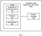
- the embodiment of the invention further provides an irradiation angle adjustment system of a lamp.
- the irradiation angle adjustment system of the lamp according to the embodiment of the present invention comprises at least a remote controller 300 and any lamp as described above, and the remote controller 300 is configured to transmit the infrared signal to the lamp.
- the remote controller 300 is further configured to be connected to the lamp in wireless communication; and the remote controller 300 is configured to send an irradiation angle adjustment start signal to the lamp and simultaneously transmit the infrared signal to the lamp; the lamp is configured to turn on the infrared receivers 202, the processor 204 and the driving motor 206 after receiving the start signal.
- the remote controller 300 is further configured to send an irradiation angle adjustment stop signal to the lamp and simultaneously turn off transmitting the infrared signal; the lamp is further configured to stop an operation of the infrared receiver 202, the processor 204 and the driving motor 206 after receiving the stop signal.
- the embodiment of the invention provides the irradiation angle adjustment scheme of the lamp.
- the lamp comprises the plurality of infrared sensors and the driving motor. Firstly, the infrared signal from the remote controller is received by the plurality of infrared receivers, then the irradiation angle adjustment value of the lamp is determined based on the plurality of infrared signal intensity values received by the plurality of infrared receivers, and then based on the irradiation angle adjustment value, the irradiation angle of the lamp is adjusted by the driving motor.
- the technical scheme provided by the embodiment of the invention adjusts the irradiation angle of the lamp based on the plurality of infrared receivers and the driving motor, and achieves better lighting effect, so as to meet the lighting needs of users in practical application. Further, when the irradiation angle of the lamp needs to be adjusted, the technical scheme provided by the embodiment of the invention controls the irradiation angle of the lamp only by operating the remote controller, so as to realize the intelligent adjustment of the irradiation angle of the lamp and achieve better irradiation effect.
Landscapes
- Engineering & Computer Science (AREA)
- Computer Networks & Wireless Communication (AREA)
- General Engineering & Computer Science (AREA)
- Physics & Mathematics (AREA)
- General Physics & Mathematics (AREA)
- Selective Calling Equipment (AREA)
- Circuit Arrangement For Electric Light Sources In General (AREA)
Claims (11)
- Abstrahlungswinkeleinstellverfahren für eine Leuchte, wobei die Leuchte mehrere Infrarotempfänger (202) und einen Antriebsmotor (206) aufweist, wobei das Verfahren die folgenden Schritte aufweist:Empfangen eines Infrarotsignals von einer Fernsteuerung (300) über die mehreren Infrarotempfänger (202);Ermitteln eines Abstrahlungswinkeleinstellwerts der Leuchte basierend auf mehreren Infrarotsignalintensitätswerten der mehreren Infrarotempfänger (202); undEinstellen eines Abstrahlungswinkels der Leuchte über den Antriebsmotor (206) basierend auf dem Abstrahlungswinkeleinstellwert,wobei die mehreren Infrarotempfänger drei Infrarotempfänger (202) umfassen, welche auf einer Verlängerung einer Ebene angebracht sind, in welcher sich die Leuchte befindet, und die Koordinaten der drei Infrarotsensoren (202) mit (0, 1), (-0,5, -0,5) und (0,5, -0,5) in einem rechtwinkligen X-Y-Koordinatensystem normiert sind, das mit der Leuchte als Ursprung aufgezogen ist,dadurch gekennzeichnet,dass der Abstrahlungswinkeleinstellwert einen X-Achsen-Einstellwert und einen Y-Achsen-Einstellwert aufweist, und das Ermitteln des Abstrahlungswinkeleinstellwerts der Leuchte basierend auf mehreren Infrarotsignalintensitätswerten der mehreren Infrarotempfänger (202) den folgenden Schritt aufweist:
Ausführen eines Proportionalüberlagerungsalgorithmus basierend auf den jeweils von den drei Infrarotempfängern (202) empfangenen Infrarotsignalintensitätswerten, um den X-Achsen-Einstellwert und den Y-Achsen-Einstellwert zu ermitteln. - Abstrahlungswinkeleinstellverfahren nach Anspruch 1, bei welchemder X-Achsen-Einstellwert = einem Infrarotsignalintensitätswert 1 * 0 + einem Infrarotsignalintensitätswert 2 * (-0,5) + einem Infrarotsignalintensitätswert 3 * 0,5 ist;der Y-Achsen-Einstellwert = einem Infrarotsignalintensitätswert 1 * 1 + einem Infrarotsignalintensitätswert 2 * (-0,5) + einem Infrarotsignalintensitätswert 3 * (-0,5) ist,wobei der Infrarotsignalintensitätswert 1, der Infrarotsignalintensitätswert 2 und der Infrarotsignalintensitätswert 3 jeweils von den drei Infrarotempfängern (202) empfangene Infrarotsignalintensitätswerte sind.
- Abstrahlungswinkeleinstellverfahren nach Anspruch 1 oder 2, ferner mit dem Schritt:
Aktualisieren des X-Achsen Einstellwerts und des Y-Achsen-Einstellwerts in Echtzeit, basierend auf den in Echtzeit aktualisierten Infrarotsignalintensitätswerten, in einem Vorgang des Einstellens des Abstrahlungswinkels der Leuchte über den Antriebsmotor (206), bis der X-Achsen-Einstellwert und der Y-Achsen-Einstellwert null sind, um das Einstellen des Abstrahlungswinkels der Leuchte über den Antriebsmotor (206) zu stoppen. - Abstrahlungswinkeleinstellverfahren nach einem der Ansprüche 1-3, ferner mit dem Schritt:
Empfangen eines Abstrahlungswinkeleinstellstoppsignals von der Fernsteuerung (300), und Stoppen des Einstellens des Abstrahlungswinkels der Leuchte über den Antriebsmotor (206). - Leuchte mit einstellbarem Abstrahlungswinkel, wobei die Leuchte mehrere Infrarotempfänger (202), einen Antriebsmotor (206) und einen Prozessor (204) aufweist, wobeidie mehreren Infrarotempfänger (202) dazu ausgebildet sind, ein Infrarotsignal von einer Fernsteuerung (300) zu empfangen und mehrere Infrarotsignalintensitätswerte der mehreren Infrarotempfänger (202) an den Prozessor (204) zu übertragen;der Prozessor (204) dazu ausgebildet ist, einen Abstrahlungswinkeleinstellwert der Leuchte basierend auf den mehreren Infrarotsignalintensitätswerten zu ermitteln und die den Abstrahlungswinkeleinstellwert an den Antriebsmotor (206) zu übertragen; undder Antriebsmotor (206) dazu ausgebildet ist, einen Abstrahlungswinkel der Leuchte basierend auf dem Abstrahlungswinkeleinstellwert einzustellen,wobei die mehreren Infrarotempfänger (202) drei Infrarotempfänger (202) aufweisen, die drei Infrarotempfänger (202) auf einer Verlängerung einer Ebene angebracht sind, in welcher sich die Leuchte befindet, und Koordinaten der drei Infrarotsensoren (202) mit (0, 1), (-0,5, -0,5) und (0,5, -0,5) in einem rechtwinkligen X-Y-Koordinatensystem normiert sind, das mit der Leuchte als Ursprung aufgezogen ist,dadurch gekennzeichnet,dass der Abstrahlungswinkeleinstellwert einen X-Achsen-Einstellwert und einen Y-Achsen-Einstellwert aufweist,der Prozessor (204) ferner dazu ausgebildet ist, einen Proportionalüberlagerungsalgorithmus basierend auf den jeweils von den drei Infrarotempfängern (202) empfangenen Infrarotsignalintensitätswerten auszuführen, um den X-Achsen-Einstellwert und den Y-Achsen-Einstellwert zu ermitteln.
- Leuchte nach Anspruch 5, bei welcherder X-Achsen-Einstellwert = einem Infrarotsignalintensitätswert 1 * 0 + einem Infrarotsignalintensitätswert 2 * (-0,5) + einem Infrarotsignalintensitätswert 3 * 0,5 ist;der Y-Achsen-Einstellwert = einem Infrarotsignalintensitätswert 1 * 1 + einem Infrarotsignalintensitätswert 2 * (-0,5) + einem Infrarotsignalintensitätswert 3 * (-0,5) ist,wobei der Infrarotsignalintensitätswert 1, der Infrarotsignalintensitätswert 2 und der Infrarotsignalintensitätswert 3 jeweils von den drei Infrarotempfängern (202) empfangene Infrarotsignalintensitätswerte sind.
- Leuchte nach Anspruch 5 oder 6, bei welcher der Prozessor (204) ferner dazu ausgebildet ist, in einem Vorgang des Einstellens des Abstrahlungswinkels der Leuchte durch den Antriebsmotor (206), den X-Achsen-Einstellwert und den Y-Achsen-Einstellwert, die in Echtzeit aktualisiert werden, in Echtzeit einzustellen, bis der X-Achsen-Einstellwert und der Y-Achsen-Einstellwert null sind, um das Einstellen des Abstrahlungswinkels der Leuchte über den Antriebsmotor (206) zu stoppen.
- Leuchte nach einem der Ansprüche 5 - 7, bei welcher der Prozessor (204) ferner dazu ausgebildet ist, das Einstellen des Abstrahlungswinkels der Leuchte über den Antriebsmotor (206) nach dem Empfang eines Abstrahlungswinkeleinstellstoppsignals von der Fernsteuerung (300) zu stoppen.
- Abstrahlungswinkeleinstellsystem einer Leuchte mit:
einer Fernsteuerung (300) und der Leuchte nach einem der Ansprüche 5-8, wobei die Fernsteuerung (300) dazu ausgebildet ist, das Infrarotsignal an die Leuchte zu übertragen. - Abstrahlungswinkeleinstellsystem nach Anspruch 9, bei welchemdie Fernsteuerung (300) ferner dazu ausgebildet ist, mit der Leuchte in drahtloser Kommunikation verbunden zu sein, und die Fernsteuerung (300) dazu ausgebildet ist, ein Abstrahlungswinkeleinstellstartsignal an die Leuchte zu senden und gleichzeitig das Infrarotsignal an die Leuchte zu übertragen; unddie Leuchte dazu ausgebildet ist, nach dem Empfang des Abstrahlungswinkeleinstellstartsignals die mehreren Infrarotempfänger (202), den Prozessor (204) und den Antriebsmotor (206) einzuschalten.
- Abstrahlungswinkeleinstellsystem nach Anspruch 9 oder 10, bei welchemdie Fernsteuerung (300) ferner dazu ausgebildet ist, ein Abstrahlungswinkeleinstellstoppsignal an die Leuchte zu senden und gleichzeitig die Übertragung des Infrarotsignals an die Leuchte abzuschalten; unddie Leuchte ferner dazu ausgebildet ist, bei Empfang des Abstrahlungswinkeleinstellstoppsignals den Betrieb der mehreren Infrarotempfänger (202), des Prozessors (204) und des Antriebsmotor (206) zu stoppen.
Applications Claiming Priority (3)
| Application Number | Priority Date | Filing Date | Title |
|---|---|---|---|
| CN201920138528.3U CN210641116U (zh) | 2019-01-25 | 2019-01-25 | 可调节照射角度的灯具和灯具的照射角度调节系统 |
| CN201910074698.4A CN109640493A (zh) | 2019-01-25 | 2019-01-25 | 灯具的照射角度调节方法、系统和可调节照射角度的灯具 |
| PCT/CN2019/130138 WO2020151462A1 (zh) | 2019-01-25 | 2019-12-30 | 灯具的照射角度调节方法、系统和可调节照射角度的灯具 |
Publications (3)
| Publication Number | Publication Date |
|---|---|
| EP3911122A1 EP3911122A1 (de) | 2021-11-17 |
| EP3911122A4 EP3911122A4 (de) | 2022-02-23 |
| EP3911122B1 true EP3911122B1 (de) | 2024-03-20 |
Family
ID=71736122
Family Applications (1)
| Application Number | Title | Priority Date | Filing Date |
|---|---|---|---|
| EP19910946.3A Active EP3911122B1 (de) | 2019-01-25 | 2019-12-30 | Verfahren und system zur einstellung des strahlwinkels einer lampe und lampe mit einstellbarem strahlwinkel |
Country Status (3)
| Country | Link |
|---|---|
| US (1) | US11968760B2 (de) |
| EP (1) | EP3911122B1 (de) |
| WO (1) | WO2020151462A1 (de) |
Family Cites Families (11)
| Publication number | Priority date | Publication date | Assignee | Title |
|---|---|---|---|---|
| US9955551B2 (en) * | 2002-07-12 | 2018-04-24 | Yechezkal Evan Spero | Detector controlled illuminating system |
| WO2004038962A1 (ja) * | 2002-10-24 | 2004-05-06 | Nakagawa Laboratories, Inc. | 照明光通信装置 |
| EP1839014A2 (de) * | 2005-01-12 | 2007-10-03 | Koninklijke Philips Electronics N.V. | Scheinwerfereinheit mit mitteln zum einstellen der lichtstrahlrichtung |
| EP2217852A4 (de) * | 2007-11-08 | 2014-03-19 | Lite On It Corp | 2d-gesten-lichtsteuerung auf grundlage von ultraschallechoerkennung |
| US7866848B2 (en) * | 2008-07-07 | 2011-01-11 | Edison Opto Corporation | Illumination system capable of automatically adjusting illumination direction according to human body's signal |
| US20150308642A1 (en) * | 2014-04-23 | 2015-10-29 | General Led, Inc. | Self-Aiming Track Light Fixture System and Method |
| CN106482005A (zh) * | 2015-08-25 | 2017-03-08 | 上海本星电子科技有限公司 | 一体化遥控灯及其锥形光束遥控器 |
| CN205014298U (zh) * | 2015-10-20 | 2016-02-03 | 广州力铭光电科技有限公司 | Led会议灯照射角度控制系统 |
| CN206918814U (zh) * | 2017-07-14 | 2018-01-23 | 四川溯源科技有限公司 | 一种可调节照射角度的灯具 |
| US11184967B2 (en) * | 2018-05-07 | 2021-11-23 | Zane Coleman | Angularly varying light emitting device with an imager |
| CN109640493A (zh) * | 2019-01-25 | 2019-04-16 | 欧普照明股份有限公司 | 灯具的照射角度调节方法、系统和可调节照射角度的灯具 |
-
2019
- 2019-12-30 WO PCT/CN2019/130138 patent/WO2020151462A1/zh not_active Ceased
- 2019-12-30 EP EP19910946.3A patent/EP3911122B1/de active Active
-
2021
- 2021-08-13 US US17/402,266 patent/US11968760B2/en active Active
Also Published As
| Publication number | Publication date |
|---|---|
| WO2020151462A1 (zh) | 2020-07-30 |
| US11968760B2 (en) | 2024-04-23 |
| EP3911122A4 (de) | 2022-02-23 |
| EP3911122A1 (de) | 2021-11-17 |
| US20210378075A1 (en) | 2021-12-02 |
Similar Documents
| Publication | Publication Date | Title |
|---|---|---|
| US20230366530A1 (en) | Directionally maniupulatable view enhancement apparatus and system | |
| US20150308642A1 (en) | Self-Aiming Track Light Fixture System and Method | |
| KR101573218B1 (ko) | 이동식 조명 장치 및 그 제어 방법 | |
| CN103777637A (zh) | 无反射板激光自主导航agv小车及其导航方法 | |
| EP2443381A1 (de) | Intelligente lichtarmatur mit manueller punktverfolgungsfunktion | |
| CN103135589A (zh) | 可任意改变投射区域的射灯、跟随投射系统及其实现方法 | |
| WO2009136270A3 (en) | "stage -lighting apparatus and method for controlling the orientation of a light beam emitted by said apparatus" | |
| EP1515210A3 (de) | Robotersystem und Steuerverfahren hierzu | |
| CN202649819U (zh) | 一种舞台灯光跟随装置 | |
| CA2489159A1 (en) | Light controlled movable toy | |
| EP3911122B1 (de) | Verfahren und system zur einstellung des strahlwinkels einer lampe und lampe mit einstellbarem strahlwinkel | |
| WO2015038595A1 (en) | Kinematic light control system | |
| US9718395B1 (en) | Apparatus and method for controlling a vehicle light with adjustable light output | |
| JP2010257742A (ja) | 照明システム | |
| JPH0971386A (ja) | 遠隔操作装置 | |
| CA2548688A1 (en) | Inductively coupled plasma alignment apparatus and method | |
| CN120096440A (zh) | 自闭环车灯参数配置系统 | |
| CN109640493A (zh) | 灯具的照射角度调节方法、系统和可调节照射角度的灯具 | |
| CN119717796A (zh) | 一种集成自动化定点和划线功能的建筑机器人及其路径规划方法 | |
| CN210641116U (zh) | 可调节照射角度的灯具和灯具的照射角度调节系统 | |
| JP5344215B2 (ja) | レーザー墨出し器及びそれを用いたレーザーシステム | |
| JP2746508B2 (ja) | 舞台用照明装置の制御方法 | |
| EP3052997B1 (de) | Resonanzbewegungsdämpfungssystem für eine automatisierte leuchte | |
| JP2014089537A (ja) | ビジョン走行システム | |
| JPH07101167B2 (ja) | 画像センサの照明方法およびその装置 |
Legal Events
| Date | Code | Title | Description |
|---|---|---|---|
| STAA | Information on the status of an ep patent application or granted ep patent |
Free format text: STATUS: THE INTERNATIONAL PUBLICATION HAS BEEN MADE |
|
| PUAI | Public reference made under article 153(3) epc to a published international application that has entered the european phase |
Free format text: ORIGINAL CODE: 0009012 |
|
| STAA | Information on the status of an ep patent application or granted ep patent |
Free format text: STATUS: REQUEST FOR EXAMINATION WAS MADE |
|
| 17P | Request for examination filed |
Effective date: 20210809 |
|
| AK | Designated contracting states |
Kind code of ref document: A1 Designated state(s): AL AT BE BG CH CY CZ DE DK EE ES FI FR GB GR HR HU IE IS IT LI LT LU LV MC MK MT NL NO PL PT RO RS SE SI SK SM TR |
|
| A4 | Supplementary search report drawn up and despatched |
Effective date: 20220126 |
|
| RIC1 | Information provided on ipc code assigned before grant |
Ipc: F21V 21/15 20060101ALN20220120BHEP Ipc: H05B 47/13 20200101ALI20220120BHEP Ipc: H05B 47/195 20200101AFI20220120BHEP |
|
| DAV | Request for validation of the european patent (deleted) | ||
| DAX | Request for extension of the european patent (deleted) | ||
| REG | Reference to a national code |
Ref country code: DE Ref legal event code: R079 Free format text: PREVIOUS MAIN CLASS: H05B0039040000 Ipc: H05B0047195000 Ref country code: DE Ref legal event code: R079 Ref document number: 602019048825 Country of ref document: DE Free format text: PREVIOUS MAIN CLASS: H05B0039040000 Ipc: H05B0047195000 |
|
| RIC1 | Information provided on ipc code assigned before grant |
Ipc: F21V 21/15 20060101ALN20230530BHEP Ipc: G08C 23/04 20060101ALI20230530BHEP Ipc: H05B 47/13 20200101ALI20230530BHEP Ipc: H05B 47/195 20200101AFI20230530BHEP |
|
| RIC1 | Information provided on ipc code assigned before grant |
Ipc: F21V 21/15 20060101ALN20230615BHEP Ipc: G08C 23/04 20060101ALI20230615BHEP Ipc: H05B 47/13 20200101ALI20230615BHEP Ipc: H05B 47/195 20200101AFI20230615BHEP |
|
| GRAP | Despatch of communication of intention to grant a patent |
Free format text: ORIGINAL CODE: EPIDOSNIGR1 |
|
| STAA | Information on the status of an ep patent application or granted ep patent |
Free format text: STATUS: GRANT OF PATENT IS INTENDED |
|
| INTG | Intention to grant announced |
Effective date: 20231005 |
|
| GRAS | Grant fee paid |
Free format text: ORIGINAL CODE: EPIDOSNIGR3 |
|
| GRAA | (expected) grant |
Free format text: ORIGINAL CODE: 0009210 |
|
| STAA | Information on the status of an ep patent application or granted ep patent |
Free format text: STATUS: THE PATENT HAS BEEN GRANTED |
|
| AK | Designated contracting states |
Kind code of ref document: B1 Designated state(s): AL AT BE BG CH CY CZ DE DK EE ES FI FR GB GR HR HU IE IS IT LI LT LU LV MC MK MT NL NO PL PT RO RS SE SI SK SM TR |
|
| REG | Reference to a national code |
Ref country code: GB Ref legal event code: FG4D |
|
| REG | Reference to a national code |
Ref country code: CH Ref legal event code: EP |
|
| REG | Reference to a national code |
Ref country code: IE Ref legal event code: FG4D |
|
| REG | Reference to a national code |
Ref country code: DE Ref legal event code: R096 Ref document number: 602019048825 Country of ref document: DE |
|
| PG25 | Lapsed in a contracting state [announced via postgrant information from national office to epo] |
Ref country code: LT Free format text: LAPSE BECAUSE OF FAILURE TO SUBMIT A TRANSLATION OF THE DESCRIPTION OR TO PAY THE FEE WITHIN THE PRESCRIBED TIME-LIMIT Effective date: 20240320 |
|
| REG | Reference to a national code |
Ref country code: NL Ref legal event code: FP Ref country code: LT Ref legal event code: MG9D |
|
| PG25 | Lapsed in a contracting state [announced via postgrant information from national office to epo] |
Ref country code: GR Free format text: LAPSE BECAUSE OF FAILURE TO SUBMIT A TRANSLATION OF THE DESCRIPTION OR TO PAY THE FEE WITHIN THE PRESCRIBED TIME-LIMIT Effective date: 20240621 |
|
| PG25 | Lapsed in a contracting state [announced via postgrant information from national office to epo] |
Ref country code: RS Free format text: LAPSE BECAUSE OF FAILURE TO SUBMIT A TRANSLATION OF THE DESCRIPTION OR TO PAY THE FEE WITHIN THE PRESCRIBED TIME-LIMIT Effective date: 20240620 Ref country code: HR Free format text: LAPSE BECAUSE OF FAILURE TO SUBMIT A TRANSLATION OF THE DESCRIPTION OR TO PAY THE FEE WITHIN THE PRESCRIBED TIME-LIMIT Effective date: 20240320 |
|
| PG25 | Lapsed in a contracting state [announced via postgrant information from national office to epo] |
Ref country code: RS Free format text: LAPSE BECAUSE OF FAILURE TO SUBMIT A TRANSLATION OF THE DESCRIPTION OR TO PAY THE FEE WITHIN THE PRESCRIBED TIME-LIMIT Effective date: 20240620 Ref country code: NO Free format text: LAPSE BECAUSE OF FAILURE TO SUBMIT A TRANSLATION OF THE DESCRIPTION OR TO PAY THE FEE WITHIN THE PRESCRIBED TIME-LIMIT Effective date: 20240620 Ref country code: LT Free format text: LAPSE BECAUSE OF FAILURE TO SUBMIT A TRANSLATION OF THE DESCRIPTION OR TO PAY THE FEE WITHIN THE PRESCRIBED TIME-LIMIT Effective date: 20240320 Ref country code: HR Free format text: LAPSE BECAUSE OF FAILURE TO SUBMIT A TRANSLATION OF THE DESCRIPTION OR TO PAY THE FEE WITHIN THE PRESCRIBED TIME-LIMIT Effective date: 20240320 Ref country code: GR Free format text: LAPSE BECAUSE OF FAILURE TO SUBMIT A TRANSLATION OF THE DESCRIPTION OR TO PAY THE FEE WITHIN THE PRESCRIBED TIME-LIMIT Effective date: 20240621 Ref country code: FI Free format text: LAPSE BECAUSE OF FAILURE TO SUBMIT A TRANSLATION OF THE DESCRIPTION OR TO PAY THE FEE WITHIN THE PRESCRIBED TIME-LIMIT Effective date: 20240320 Ref country code: BG Free format text: LAPSE BECAUSE OF FAILURE TO SUBMIT A TRANSLATION OF THE DESCRIPTION OR TO PAY THE FEE WITHIN THE PRESCRIBED TIME-LIMIT Effective date: 20240320 |
|
| REG | Reference to a national code |
Ref country code: AT Ref legal event code: MK05 Ref document number: 1668952 Country of ref document: AT Kind code of ref document: T Effective date: 20240320 |
|
| PG25 | Lapsed in a contracting state [announced via postgrant information from national office to epo] |
Ref country code: SE Free format text: LAPSE BECAUSE OF FAILURE TO SUBMIT A TRANSLATION OF THE DESCRIPTION OR TO PAY THE FEE WITHIN THE PRESCRIBED TIME-LIMIT Effective date: 20240320 Ref country code: LV Free format text: LAPSE BECAUSE OF FAILURE TO SUBMIT A TRANSLATION OF THE DESCRIPTION OR TO PAY THE FEE WITHIN THE PRESCRIBED TIME-LIMIT Effective date: 20240320 |
|
| PG25 | Lapsed in a contracting state [announced via postgrant information from national office to epo] |
Ref country code: IS Free format text: LAPSE BECAUSE OF FAILURE TO SUBMIT A TRANSLATION OF THE DESCRIPTION OR TO PAY THE FEE WITHIN THE PRESCRIBED TIME-LIMIT Effective date: 20240720 |
|
| PG25 | Lapsed in a contracting state [announced via postgrant information from national office to epo] |
Ref country code: SM Free format text: LAPSE BECAUSE OF FAILURE TO SUBMIT A TRANSLATION OF THE DESCRIPTION OR TO PAY THE FEE WITHIN THE PRESCRIBED TIME-LIMIT Effective date: 20240320 Ref country code: PT Free format text: LAPSE BECAUSE OF FAILURE TO SUBMIT A TRANSLATION OF THE DESCRIPTION OR TO PAY THE FEE WITHIN THE PRESCRIBED TIME-LIMIT Effective date: 20240722 |
|
| PG25 | Lapsed in a contracting state [announced via postgrant information from national office to epo] |
Ref country code: ES Free format text: LAPSE BECAUSE OF FAILURE TO SUBMIT A TRANSLATION OF THE DESCRIPTION OR TO PAY THE FEE WITHIN THE PRESCRIBED TIME-LIMIT Effective date: 20240320 |
|
| PG25 | Lapsed in a contracting state [announced via postgrant information from national office to epo] |
Ref country code: CZ Free format text: LAPSE BECAUSE OF FAILURE TO SUBMIT A TRANSLATION OF THE DESCRIPTION OR TO PAY THE FEE WITHIN THE PRESCRIBED TIME-LIMIT Effective date: 20240320 Ref country code: EE Free format text: LAPSE BECAUSE OF FAILURE TO SUBMIT A TRANSLATION OF THE DESCRIPTION OR TO PAY THE FEE WITHIN THE PRESCRIBED TIME-LIMIT Effective date: 20240320 |
|
| PG25 | Lapsed in a contracting state [announced via postgrant information from national office to epo] |
Ref country code: AT Free format text: LAPSE BECAUSE OF FAILURE TO SUBMIT A TRANSLATION OF THE DESCRIPTION OR TO PAY THE FEE WITHIN THE PRESCRIBED TIME-LIMIT Effective date: 20240320 |
|
| PG25 | Lapsed in a contracting state [announced via postgrant information from national office to epo] |
Ref country code: PL Free format text: LAPSE BECAUSE OF FAILURE TO SUBMIT A TRANSLATION OF THE DESCRIPTION OR TO PAY THE FEE WITHIN THE PRESCRIBED TIME-LIMIT Effective date: 20240320 |
|
| PG25 | Lapsed in a contracting state [announced via postgrant information from national office to epo] |
Ref country code: SK Free format text: LAPSE BECAUSE OF FAILURE TO SUBMIT A TRANSLATION OF THE DESCRIPTION OR TO PAY THE FEE WITHIN THE PRESCRIBED TIME-LIMIT Effective date: 20240320 |
|
| PG25 | Lapsed in a contracting state [announced via postgrant information from national office to epo] |
Ref country code: SM Free format text: LAPSE BECAUSE OF FAILURE TO SUBMIT A TRANSLATION OF THE DESCRIPTION OR TO PAY THE FEE WITHIN THE PRESCRIBED TIME-LIMIT Effective date: 20240320 Ref country code: SK Free format text: LAPSE BECAUSE OF FAILURE TO SUBMIT A TRANSLATION OF THE DESCRIPTION OR TO PAY THE FEE WITHIN THE PRESCRIBED TIME-LIMIT Effective date: 20240320 Ref country code: RO Free format text: LAPSE BECAUSE OF FAILURE TO SUBMIT A TRANSLATION OF THE DESCRIPTION OR TO PAY THE FEE WITHIN THE PRESCRIBED TIME-LIMIT Effective date: 20240320 Ref country code: PT Free format text: LAPSE BECAUSE OF FAILURE TO SUBMIT A TRANSLATION OF THE DESCRIPTION OR TO PAY THE FEE WITHIN THE PRESCRIBED TIME-LIMIT Effective date: 20240722 Ref country code: PL Free format text: LAPSE BECAUSE OF FAILURE TO SUBMIT A TRANSLATION OF THE DESCRIPTION OR TO PAY THE FEE WITHIN THE PRESCRIBED TIME-LIMIT Effective date: 20240320 Ref country code: IS Free format text: LAPSE BECAUSE OF FAILURE TO SUBMIT A TRANSLATION OF THE DESCRIPTION OR TO PAY THE FEE WITHIN THE PRESCRIBED TIME-LIMIT Effective date: 20240720 Ref country code: ES Free format text: LAPSE BECAUSE OF FAILURE TO SUBMIT A TRANSLATION OF THE DESCRIPTION OR TO PAY THE FEE WITHIN THE PRESCRIBED TIME-LIMIT Effective date: 20240320 Ref country code: EE Free format text: LAPSE BECAUSE OF FAILURE TO SUBMIT A TRANSLATION OF THE DESCRIPTION OR TO PAY THE FEE WITHIN THE PRESCRIBED TIME-LIMIT Effective date: 20240320 Ref country code: CZ Free format text: LAPSE BECAUSE OF FAILURE TO SUBMIT A TRANSLATION OF THE DESCRIPTION OR TO PAY THE FEE WITHIN THE PRESCRIBED TIME-LIMIT Effective date: 20240320 Ref country code: AT Free format text: LAPSE BECAUSE OF FAILURE TO SUBMIT A TRANSLATION OF THE DESCRIPTION OR TO PAY THE FEE WITHIN THE PRESCRIBED TIME-LIMIT Effective date: 20240320 |
|
| PG25 | Lapsed in a contracting state [announced via postgrant information from national office to epo] |
Ref country code: IT Free format text: LAPSE BECAUSE OF FAILURE TO SUBMIT A TRANSLATION OF THE DESCRIPTION OR TO PAY THE FEE WITHIN THE PRESCRIBED TIME-LIMIT Effective date: 20240320 |
|
| REG | Reference to a national code |
Ref country code: DE Ref legal event code: R097 Ref document number: 602019048825 Country of ref document: DE |
|
| PG25 | Lapsed in a contracting state [announced via postgrant information from national office to epo] |
Ref country code: IT Free format text: LAPSE BECAUSE OF FAILURE TO SUBMIT A TRANSLATION OF THE DESCRIPTION OR TO PAY THE FEE WITHIN THE PRESCRIBED TIME-LIMIT Effective date: 20240320 |
|
| PG25 | Lapsed in a contracting state [announced via postgrant information from national office to epo] |
Ref country code: DK Free format text: LAPSE BECAUSE OF FAILURE TO SUBMIT A TRANSLATION OF THE DESCRIPTION OR TO PAY THE FEE WITHIN THE PRESCRIBED TIME-LIMIT Effective date: 20240320 |
|
| PGFP | Annual fee paid to national office [announced via postgrant information from national office to epo] |
Ref country code: BE Payment date: 20241220 Year of fee payment: 6 |
|
| PGFP | Annual fee paid to national office [announced via postgrant information from national office to epo] |
Ref country code: FR Payment date: 20241224 Year of fee payment: 6 |
|
| PLBE | No opposition filed within time limit |
Free format text: ORIGINAL CODE: 0009261 |
|
| STAA | Information on the status of an ep patent application or granted ep patent |
Free format text: STATUS: NO OPPOSITION FILED WITHIN TIME LIMIT |
|
| PG25 | Lapsed in a contracting state [announced via postgrant information from national office to epo] |
Ref country code: DK Free format text: LAPSE BECAUSE OF FAILURE TO SUBMIT A TRANSLATION OF THE DESCRIPTION OR TO PAY THE FEE WITHIN THE PRESCRIBED TIME-LIMIT Effective date: 20240320 |
|
| 26N | No opposition filed |
Effective date: 20241223 |
|
| PG25 | Lapsed in a contracting state [announced via postgrant information from national office to epo] |
Ref country code: SI Free format text: LAPSE BECAUSE OF FAILURE TO SUBMIT A TRANSLATION OF THE DESCRIPTION OR TO PAY THE FEE WITHIN THE PRESCRIBED TIME-LIMIT Effective date: 20240320 |
|
| PG25 | Lapsed in a contracting state [announced via postgrant information from national office to epo] |
Ref country code: MC Free format text: LAPSE BECAUSE OF FAILURE TO SUBMIT A TRANSLATION OF THE DESCRIPTION OR TO PAY THE FEE WITHIN THE PRESCRIBED TIME-LIMIT Effective date: 20240320 |
|
| REG | Reference to a national code |
Ref country code: CH Ref legal event code: PL |
|
| PG25 | Lapsed in a contracting state [announced via postgrant information from national office to epo] |
Ref country code: LU Free format text: LAPSE BECAUSE OF NON-PAYMENT OF DUE FEES Effective date: 20241230 |
|
| PG25 | Lapsed in a contracting state [announced via postgrant information from national office to epo] |
Ref country code: CH Free format text: LAPSE BECAUSE OF NON-PAYMENT OF DUE FEES Effective date: 20241231 |
|
| PG25 | Lapsed in a contracting state [announced via postgrant information from national office to epo] |
Ref country code: IE Free format text: LAPSE BECAUSE OF NON-PAYMENT OF DUE FEES Effective date: 20241230 |
|
| PGFP | Annual fee paid to national office [announced via postgrant information from national office to epo] |
Ref country code: NL Payment date: 20251127 Year of fee payment: 7 |
|
| PGFP | Annual fee paid to national office [announced via postgrant information from national office to epo] |
Ref country code: GB Payment date: 20251229 Year of fee payment: 7 |
|
| PGFP | Annual fee paid to national office [announced via postgrant information from national office to epo] |
Ref country code: DE Payment date: 20251231 Year of fee payment: 7 |