EP3911498B1 - Surveillance et régulation du processus d'une fabrication additive d'une pièce à usiner - Google Patents
Surveillance et régulation du processus d'une fabrication additive d'une pièce à usiner Download PDFInfo
- Publication number
- EP3911498B1 EP3911498B1 EP20706975.8A EP20706975A EP3911498B1 EP 3911498 B1 EP3911498 B1 EP 3911498B1 EP 20706975 A EP20706975 A EP 20706975A EP 3911498 B1 EP3911498 B1 EP 3911498B1
- Authority
- EP
- European Patent Office
- Prior art keywords
- detector
- workpiece
- light
- unit
- designed
- Prior art date
- Legal status (The legal status is an assumption and is not a legal conclusion. Google has not performed a legal analysis and makes no representation as to the accuracy of the status listed.)
- Active
Links
Images



Classifications
-
- B—PERFORMING OPERATIONS; TRANSPORTING
- B29—WORKING OF PLASTICS; WORKING OF SUBSTANCES IN A PLASTIC STATE IN GENERAL
- B29C—SHAPING OR JOINING OF PLASTICS; SHAPING OF MATERIAL IN A PLASTIC STATE, NOT OTHERWISE PROVIDED FOR; AFTER-TREATMENT OF THE SHAPED PRODUCTS, e.g. REPAIRING
- B29C64/00—Additive manufacturing, i.e. manufacturing of three-dimensional [3D] objects by additive deposition, additive agglomeration or additive layering, e.g. by 3D printing, stereolithography or selective laser sintering
- B29C64/10—Processes of additive manufacturing
- B29C64/141—Processes of additive manufacturing using only solid materials
- B29C64/153—Processes of additive manufacturing using only solid materials using layers of powder being selectively joined, e.g. by selective laser sintering or melting
-
- B—PERFORMING OPERATIONS; TRANSPORTING
- B22—CASTING; POWDER METALLURGY
- B22F—WORKING METALLIC POWDER; MANUFACTURE OF ARTICLES FROM METALLIC POWDER; MAKING METALLIC POWDER; APPARATUS OR DEVICES SPECIALLY ADAPTED FOR METALLIC POWDER
- B22F10/00—Additive manufacturing of workpieces or articles from metallic powder
- B22F10/30—Process control
- B22F10/36—Process control of energy beam parameters
- B22F10/366—Scanning parameters, e.g. hatch distance or scanning strategy
-
- B—PERFORMING OPERATIONS; TRANSPORTING
- B22—CASTING; POWDER METALLURGY
- B22F—WORKING METALLIC POWDER; MANUFACTURE OF ARTICLES FROM METALLIC POWDER; MAKING METALLIC POWDER; APPARATUS OR DEVICES SPECIALLY ADAPTED FOR METALLIC POWDER
- B22F12/00—Apparatus or devices specially adapted for additive manufacturing; Auxiliary means for additive manufacturing; Combinations of additive manufacturing apparatus or devices with other processing apparatus or devices
- B22F12/40—Radiation means
- B22F12/44—Radiation means characterised by the configuration of the radiation means
-
- B—PERFORMING OPERATIONS; TRANSPORTING
- B22—CASTING; POWDER METALLURGY
- B22F—WORKING METALLIC POWDER; MANUFACTURE OF ARTICLES FROM METALLIC POWDER; MAKING METALLIC POWDER; APPARATUS OR DEVICES SPECIALLY ADAPTED FOR METALLIC POWDER
- B22F12/00—Apparatus or devices specially adapted for additive manufacturing; Auxiliary means for additive manufacturing; Combinations of additive manufacturing apparatus or devices with other processing apparatus or devices
- B22F12/40—Radiation means
- B22F12/49—Scanners
-
- B—PERFORMING OPERATIONS; TRANSPORTING
- B22—CASTING; POWDER METALLURGY
- B22F—WORKING METALLIC POWDER; MANUFACTURE OF ARTICLES FROM METALLIC POWDER; MAKING METALLIC POWDER; APPARATUS OR DEVICES SPECIALLY ADAPTED FOR METALLIC POWDER
- B22F12/00—Apparatus or devices specially adapted for additive manufacturing; Auxiliary means for additive manufacturing; Combinations of additive manufacturing apparatus or devices with other processing apparatus or devices
- B22F12/90—Means for process control, e.g. cameras or sensors
-
- B—PERFORMING OPERATIONS; TRANSPORTING
- B23—MACHINE TOOLS; METAL-WORKING NOT OTHERWISE PROVIDED FOR
- B23K—SOLDERING OR UNSOLDERING; WELDING; CLADDING OR PLATING BY SOLDERING OR WELDING; CUTTING BY APPLYING HEAT LOCALLY, e.g. FLAME CUTTING; WORKING BY LASER BEAM
- B23K26/00—Working by laser beam, e.g. welding, cutting or boring
- B23K26/02—Positioning or observing the workpiece, e.g. with respect to the point of impact; Aligning, aiming or focusing the laser beam
- B23K26/03—Observing, e.g. monitoring, the workpiece
- B23K26/034—Observing the temperature of the workpiece
-
- B—PERFORMING OPERATIONS; TRANSPORTING
- B23—MACHINE TOOLS; METAL-WORKING NOT OTHERWISE PROVIDED FOR
- B23K—SOLDERING OR UNSOLDERING; WELDING; CLADDING OR PLATING BY SOLDERING OR WELDING; CUTTING BY APPLYING HEAT LOCALLY, e.g. FLAME CUTTING; WORKING BY LASER BEAM
- B23K26/00—Working by laser beam, e.g. welding, cutting or boring
- B23K26/34—Laser welding for purposes other than joining
-
- B—PERFORMING OPERATIONS; TRANSPORTING
- B29—WORKING OF PLASTICS; WORKING OF SUBSTANCES IN A PLASTIC STATE IN GENERAL
- B29C—SHAPING OR JOINING OF PLASTICS; SHAPING OF MATERIAL IN A PLASTIC STATE, NOT OTHERWISE PROVIDED FOR; AFTER-TREATMENT OF THE SHAPED PRODUCTS, e.g. REPAIRING
- B29C64/00—Additive manufacturing, i.e. manufacturing of three-dimensional [3D] objects by additive deposition, additive agglomeration or additive layering, e.g. by 3D printing, stereolithography or selective laser sintering
- B29C64/20—Apparatus for additive manufacturing; Details thereof or accessories therefor
- B29C64/264—Arrangements for irradiation
- B29C64/268—Arrangements for irradiation using laser beams; using electron beams [EB]
-
- B—PERFORMING OPERATIONS; TRANSPORTING
- B29—WORKING OF PLASTICS; WORKING OF SUBSTANCES IN A PLASTIC STATE IN GENERAL
- B29C—SHAPING OR JOINING OF PLASTICS; SHAPING OF MATERIAL IN A PLASTIC STATE, NOT OTHERWISE PROVIDED FOR; AFTER-TREATMENT OF THE SHAPED PRODUCTS, e.g. REPAIRING
- B29C64/00—Additive manufacturing, i.e. manufacturing of three-dimensional [3D] objects by additive deposition, additive agglomeration or additive layering, e.g. by 3D printing, stereolithography or selective laser sintering
- B29C64/30—Auxiliary operations or equipment
- B29C64/386—Data acquisition or data processing for additive manufacturing
- B29C64/393—Data acquisition or data processing for additive manufacturing for controlling or regulating additive manufacturing processes
-
- B—PERFORMING OPERATIONS; TRANSPORTING
- B33—ADDITIVE MANUFACTURING TECHNOLOGY
- B33Y—ADDITIVE MANUFACTURING, i.e. MANUFACTURING OF THREE-DIMENSIONAL [3D] OBJECTS BY ADDITIVE DEPOSITION, ADDITIVE AGGLOMERATION OR ADDITIVE LAYERING, e.g. BY 3D PRINTING, STEREOLITHOGRAPHY OR SELECTIVE LASER SINTERING
- B33Y10/00—Processes of additive manufacturing
-
- B—PERFORMING OPERATIONS; TRANSPORTING
- B33—ADDITIVE MANUFACTURING TECHNOLOGY
- B33Y—ADDITIVE MANUFACTURING, i.e. MANUFACTURING OF THREE-DIMENSIONAL [3D] OBJECTS BY ADDITIVE DEPOSITION, ADDITIVE AGGLOMERATION OR ADDITIVE LAYERING, e.g. BY 3D PRINTING, STEREOLITHOGRAPHY OR SELECTIVE LASER SINTERING
- B33Y30/00—Apparatus for additive manufacturing; Details thereof or accessories therefor
-
- B—PERFORMING OPERATIONS; TRANSPORTING
- B33—ADDITIVE MANUFACTURING TECHNOLOGY
- B33Y—ADDITIVE MANUFACTURING, i.e. MANUFACTURING OF THREE-DIMENSIONAL [3D] OBJECTS BY ADDITIVE DEPOSITION, ADDITIVE AGGLOMERATION OR ADDITIVE LAYERING, e.g. BY 3D PRINTING, STEREOLITHOGRAPHY OR SELECTIVE LASER SINTERING
- B33Y50/00—Data acquisition or data processing for additive manufacturing
- B33Y50/02—Data acquisition or data processing for additive manufacturing for controlling or regulating additive manufacturing processes
-
- B—PERFORMING OPERATIONS; TRANSPORTING
- B22—CASTING; POWDER METALLURGY
- B22F—WORKING METALLIC POWDER; MANUFACTURE OF ARTICLES FROM METALLIC POWDER; MAKING METALLIC POWDER; APPARATUS OR DEVICES SPECIALLY ADAPTED FOR METALLIC POWDER
- B22F10/00—Additive manufacturing of workpieces or articles from metallic powder
- B22F10/20—Direct sintering or melting
- B22F10/28—Powder bed fusion, e.g. selective laser melting [SLM] or electron beam melting [EBM]
-
- B—PERFORMING OPERATIONS; TRANSPORTING
- B22—CASTING; POWDER METALLURGY
- B22F—WORKING METALLIC POWDER; MANUFACTURE OF ARTICLES FROM METALLIC POWDER; MAKING METALLIC POWDER; APPARATUS OR DEVICES SPECIALLY ADAPTED FOR METALLIC POWDER
- B22F10/00—Additive manufacturing of workpieces or articles from metallic powder
- B22F10/30—Process control
- B22F10/31—Calibration of process steps or apparatus settings, e.g. before or during manufacturing
-
- B—PERFORMING OPERATIONS; TRANSPORTING
- B22—CASTING; POWDER METALLURGY
- B22F—WORKING METALLIC POWDER; MANUFACTURE OF ARTICLES FROM METALLIC POWDER; MAKING METALLIC POWDER; APPARATUS OR DEVICES SPECIALLY ADAPTED FOR METALLIC POWDER
- B22F10/00—Additive manufacturing of workpieces or articles from metallic powder
- B22F10/30—Process control
- B22F10/38—Process control to achieve specific product aspects, e.g. surface smoothness, density, porosity or hollow structures
-
- B—PERFORMING OPERATIONS; TRANSPORTING
- B22—CASTING; POWDER METALLURGY
- B22F—WORKING METALLIC POWDER; MANUFACTURE OF ARTICLES FROM METALLIC POWDER; MAKING METALLIC POWDER; APPARATUS OR DEVICES SPECIALLY ADAPTED FOR METALLIC POWDER
- B22F10/00—Additive manufacturing of workpieces or articles from metallic powder
- B22F10/80—Data acquisition or data processing
- B22F10/85—Data acquisition or data processing for controlling or regulating additive manufacturing processes
-
- B—PERFORMING OPERATIONS; TRANSPORTING
- B22—CASTING; POWDER METALLURGY
- B22F—WORKING METALLIC POWDER; MANUFACTURE OF ARTICLES FROM METALLIC POWDER; MAKING METALLIC POWDER; APPARATUS OR DEVICES SPECIALLY ADAPTED FOR METALLIC POWDER
- B22F2999/00—Aspects linked to processes or compositions used in powder metallurgy
-
- Y—GENERAL TAGGING OF NEW TECHNOLOGICAL DEVELOPMENTS; GENERAL TAGGING OF CROSS-SECTIONAL TECHNOLOGIES SPANNING OVER SEVERAL SECTIONS OF THE IPC; TECHNICAL SUBJECTS COVERED BY FORMER USPC CROSS-REFERENCE ART COLLECTIONS [XRACs] AND DIGESTS
- Y02—TECHNOLOGIES OR APPLICATIONS FOR MITIGATION OR ADAPTATION AGAINST CLIMATE CHANGE
- Y02P—CLIMATE CHANGE MITIGATION TECHNOLOGIES IN THE PRODUCTION OR PROCESSING OF GOODS
- Y02P10/00—Technologies related to metal processing
- Y02P10/25—Process efficiency
Definitions
- the invention relates to a device for the additive manufacturing of a workpiece, comprising a scanning unit configured to direct a melt beam, also called a writing beam, onto a writing point on a writing surface, as well as an optical detector, a control unit, and an imaging unit.
- the invention also relates to a method for monitoring the additive manufacturing of a workpiece, as well as a method for process control of the additive manufacturing of a workpiece, and a corresponding computer program.
- document DE 10 2012 221218 A1 describes a device for laser melting with a laser source and a device for deflecting the laser beam, which is controlled by a system controller.
- the device has an optical sensor, to which infrared radiation emanating from the melted area is directed via a beam splitter.
- the device has a dispenser with which successive layers of a material can be applied to a platform.
- document DE 10 2015 207834 A1 refers to a processing machine for a manufacturing or joining process using a laser beam. imaged on an image sensor using imaging optics.
- the improved concept is based on the idea of providing a spatially resolving detector for monitoring a writing surface and dynamically changing the position of a portion of the writing surface observed by the detector during production.
- a device for additive manufacturing of a workpiece has a scanning unit configured to direct a melt beam onto a writing point on a writing surface.
- the device also has an optical detector, a control unit, and an imaging unit.
- the detector is designed as a spatially resolving detector, and the imaging unit is configured and arranged to To image a partial area of the writing surface at least two-dimensionally using the detector.
- the control unit is configured to control the device, in particular the imaging unit or the scanning unit, in order to change the position of the partial area during production.
- the detector is configured to generate at least one detector signal based on the image of the partial area.
- the device has an evaluation unit for evaluating and/or processing the at least one detector signal.
- the device has a light field camera which contains the detector.
- a light field camera offers the advantage that an asymmetric pre-embossing of edges, for example due to a predetermined triangulation direction through the structure of the hardware, is not possible.
- the melting beam may, for example, be a light beam, in particular a laser beam, an electron beam or another energy beam that is suitable for additive manufacturing, in particular for selective additive manufacturing.
- the writing surface can, for example, be a surface or part of the surface of a powder bed from which the workpiece is manufactured.
- the writing surface can include part of the powder bed surface and part of a workpiece surface.
- the writing surface can also be the workpiece surface or part of the workpiece surface, for example, in manufacturing processes without a powder bed, where, for example, material is applied and fused directly onto the workpiece surface.
- Additive manufacturing can be an additive manufacturing process, in particular a selective additive manufacturing process, for example electron beam melting, selective laser melting (SLM) or selective laser sintering (SLS).
- SLM selective laser melting
- SLS selective laser sintering
- the detector may, for example, be a camera, a camera detector or a camera sensor, or a camera may contain the detector.
- the detector is designed as a spatially resolving detector can mean that the detector has multiple pixels, in particular an array of pixels.
- the detector can contain several thousand pixels, in particular an array with a number of pixels in the range of 100,000 pixels to 10,000,000 pixels.
- the subarea can be imaged quickly, with high resolution and high quality.
- the image of the partial area on the detector occurs, for example, in the visible and/or infrared range. Accordingly, the detector is sensitive in the visible and/or infrared range.
- the term “light” can be understood to include electromagnetic waves in the visible, infrared, and/or ultraviolet ranges. Accordingly, the term “optical” can be understood to refer to light as defined in this sense.
- the scanning unit which can also be called scanning unit or deflection unit, is used in particular to deflect the melt jet in a controlled manner and thus To control the writing point on the writing surface in order to carry out the selective production of the workpiece according to a defined work order, in particular according to a defined work program.
- the two-dimensional image of the sub-area can be a two-dimensional image.
- a surface of the sub-area is not necessarily even or flat, which can lead to different heights, for example of the powder bed, within the sub-area, i.e., a topography.
- the at least two-dimensional mapping of the subarea can also be understood as a two-and-a-half-dimensional mapping, in the sense that, in addition to coordinates lying in a base plane of the writing surface or powder bed, associated topographic information, i.e., height information, is also captured by the mapping onto the detector.
- the term "two-and-a-half-dimensional" can be understood to mean that the third dimension is available as an attribute or function of the two-dimensional plane coordinates. For each pair of Cartesian plane coordinates, there is exactly one height coordinate in a two-and-a-half-dimensional model. Thus, for example, vertical walls, overhangs, or cavities, which would require a complete 3D mapping, cannot be captured with a two-dimensional mapping.
- the at least two-dimensional image of the subarea can also be a three-dimensional image.
- the evaluation and/or processing of the detector signal may, for example, include a representation of the image of the partial area, for example on a display device.
- the evaluation and/or processing may also include storage of the detector signal or of information or data determined based on the detector signal.
- the evaluation and/or processing of the detector signal may also include an evaluation of image data of the image, in particular for the detection of defects or for thermographic evaluation or assessment.
- the partial area does not cover the entire writing surface or the entire powder bed.
- the partial area is therefore smaller than an entire working area. This further increases the achievable spatial resolution and the corresponding imaging and image quality.
- the position of the partial area can be changed under the control of the control unit by deflecting imaging beams or imaging light for imaging the partial area by the scanning unit synchronously with the melt beam. This is the case, for example, in embodiments in which the imaging beam or imaging light is coupled into a beam path of the melt beam.
- the position of the partial area can be changed under the control of the imaging unit, in particular under the control of the control unit, for example in embodiments in which the camera includes its own dynamic system for changing its image area.
- the described steps of the method are repeated after changing the position of the partial area. This enables monitoring of the writing surface, in particular an area around the writing point, directly at the time of production, i.e., in real time, also referred to as "online" monitoring.
- the writing point lies within the sub-area, in particular the writing point lies
- the sub-area is always changed, meaning that the sub-area is changed in such a way that it follows a movement of the writing point or vice versa.
- the evaluation of additive manufacturing may, for example, include observing or identifying defects or potential defects or imperfections, particularly immediately in front of the writing point.
- the evaluation or observation may also include detecting bumps, defects, splashes, debris, and so on on the writing surface, which may arise, for example, during the manufacturing process or a subsequent coating process. In particular, they may have arisen during a previous writing process of neighboring structures in the vicinity of the current writing point. According to the improved concept, such disturbances and imperfections can be adequately addressed and responded to.
- the evaluation or observation of the manufacturing process can be used to take into account elevations and other defects or defects in a coating process following or included in the manufacturing process.
- the scanning unit has a beam splitter which is arranged on an input side of the scanning unit in a beam path of the melt beam.
- the scanning unit has an input side and, in particular, an output side.
- the input side faces a source of the melt beam, i.e., in particular, a heating, writing, beam, electron, or laser source, while the output side faces the writing surface or the powder bed and the workpiece.
- a source of the melt beam i.e., in particular, a heating, writing, beam, electron, or laser source
- the output side faces the writing surface or the powder bed and the workpiece.
- Such embodiments are particularly suitable for processes in which the melt beam is a laser beam, for example, for SLS or SLM processes.
- the beam splitter is arranged in particular in such a way that imaging light which strikes the beam splitter from the writing surface via the deflection unit is at least partially decoupled from the beam path of the melt beam and directed in the direction of the detector.
- the scanning unit acts on the imaging light or imaging beam in a manner analogous to that which it acts on the melting beam. Consequently, the observed subarea is always coupled to the melting beam, especially the writing point.
- the writing point is located in particular in a center or approximately in a center of the partial area. Due to the synchronous deflection of melting beam and imaging beam, the coupling of the partial area to the melting beam and the writing point is independent of a current direction or deflection of the melting beam or a corresponding deflection state of the scanning unit.
- image quality can be highest near the center of the detector array. This is exploited accordingly in such designs.
- the device includes a filter, in particular a dichroic filter, which is arranged on the beam splitter and/or between the beam splitter and the detector.
- narrow-band blocking filters in particular adapted to a laser wavelength of the melting beam, can also be used.
- melt beam is a polarized laser beam
- a polarizing filter can also be used as a beam splitter.
- the device includes the heating source, in particular the laser source or the electron beam source.
- the scanning unit includes one or more deflection mirrors which are used by the control unit to direct and deflect the melt beam and, in corresponding embodiments, also the imaging beam and thus to change the position of the partial area.
- the imaging unit has one or more actuators which are configured to track the detector and/or an objective of the imaging unit in accordance with a deflection of the melt beam by the scanning unit, in particular controlled by the control unit, in order to image the partial area.
- Movement of the melt beam during imaging of the partial area onto the detector can, for example, lead to smearing of the image content or motion blurring due to beam deflection. This can be at least partially compensated by tracking the detector or the lens.
- the device in particular the control unit, is configured to temporally couple the imaging of the partial area with a deflection of the melt jet by the scanning unit such that a movement of the melt jet during the imaging of the partial area is prevented or avoided.
- the light field camera may include a main lens and an array of microlenses arranged between the main lens and the detector.
- the array of microlenses can divide a corresponding imaging beam path into subapertures. For each of these subapertures, a separate image is then created on the detector, for example, with a slightly different viewing angle due to the spatial offset of the microlenses. From the slightly different partial images, the spatial structure of the subarea can then be calculated using triangulation methods, resulting in two-and-a-half-dimensional or three-dimensional images.
- different microlenses of the array of microlenses have different focal lengths.
- two or three lens types with different focal lengths can be used for the microlenses. This can further improve depth measurement.
- the light field camera has an objective with the main lens, wherein the objective has a focusing device.
- the focusing device is designed as an autofocus device.
- the lens of the light field camera is designed as a zoom lens, for example in order to be able to adjust the magnification or resolution in the partial area of the light field camera.
- a larger depth of field can be achieved. This can eliminate blurring that can occur, for example, along a direction of an incidence plane of the imaging beam changes, can be partially or completely compensated.
- the evaluation unit is configured to determine at least one piece of topographic information of the partial area based on the at least one detector signal.
- the topographic information can be determined in particular from depth information captured by the light field camera or from two-and-a-half-dimensional or three-dimensional information.
- the evaluation unit is configured to determine a deflection position, in particular an actual current deflection position, of the melt jet based on the at least one detector signal.
- the device comprises a focusing unit, which in particular contains an F-theta lens.
- the focusing unit is arranged between the scanning unit and the writing surface or the powder bed and serves to focus the melt jet onto the writing point.
- melt beam passes through the focusing unit, in particular the F-Theta lens, at different points with different beam inclinations due to the scanning and deflection by the scanning unit, geometric imaging errors can occur which cannot be compensated for or cannot be completely compensated for, in particular by a lens design.
- embodiments of the device that can determine the actual deflection position of the melt jet are particularly advantageous. This allows the imaging errors to be at least partially compensated.
- the melt jet is not necessarily perpendicular to the plane of the writing surface.
- a two-and-a-half-dimensional or three-dimensional image of the partial area can be obtained, which in turn allows conclusions to be drawn about the deflection angle of the melt jet, particularly by evaluating any distortion of the partial area or the image of the partial area compared to a perpendicular beam without deflection.
- the device comprises a spectroscope and/or a spectrometer configured and arranged to detect light emanating from the writing surface and, based thereon, to generate a spectrometer signal containing spectrometric or spectroscopic information about the light.
- the device can include one or more sound sensors, in particular structure-borne sound sensors or microphones.
- the sound sensor is coupled to the workpiece, for example, arranged directly on the workpiece or on a support on which the powder bed or the workpiece is located.
- a sound sensor can be used to generate sound signals that contain information about cracks, splashes, and the like that occur in the workpiece during production.
- the device may also include further sensors, for example sensors for measuring a mechanical stress in the workpiece.
- the device comprises an illumination device which is configured to at least partially illuminate the partial area.
- the lighting device can be configured to illuminate the entire writing surface or the entire powder bed. Alternatively or additionally, the lighting device can be configured to dynamically change an illumination area that includes or partially includes the sub-area, for example, coupled with a movement or change of the sub-area.
- the lighting device in particular controlled by the control unit, is configured to change the lighting area, in particular depending on a position or the change of the partial area.
- illumination can be understood, for example, as illumination with light, especially visible light.
- a wavelength or wavelength range of the illuminating light or the light for illumination is, for example, matched to a sensitivity or sensitivity spectrum of the detector.
- the illumination can improve the light available for imaging the partial area on the detector and thus the image quality of the image.
- the lighting device can switch the lighting on and off.
- the lighting device and/or the control unit can be configured such that the lighting is switched off during a thermographic imaging or thermographic examination or detection of the partial area.
- thermographic recording is not distorted by the light from the lighting device.
- the light for illumination i.e., the illumination light and/or an illumination beam
- the light for illumination can be coupled into the beam path of the melt beam. This allows the position of the illumination region to be coupled to the subregion, so that a change in the position of the illumination region can occur synchronously with a change in the position of the subregion.
- the device includes an optics for steel forming, which is arranged between the illumination device and the scanning unit or between the illumination device and the writing surface or the powder bed.
- a light source of the illumination device is arranged and configured such that it can couple light for illumination on an input side of the scanning unit into a beam path of the melt beam.
- the light source may, for example, contain one or more laser sources and/or one or more light-emitting diodes.
- the light sources can, for example, be coupled directly into the beam path of the melting beam, i.e. be arranged in the immediate vicinity of the beam path or at an edge of the beam path.
- the device may include a further beam splitter arranged between the detector and the beam splitter for coupling out the imaging light or imaging beam.
- the further beam splitter is arranged in particular such that the light source of the illumination device can couple the illumination light or the illumination beam into the beam path of the melt beam via the further beam splitter and the beam splitter.
- At least one further light source of the illumination device is arranged between the scanning unit and the writing surface or the powder bed.
- the further light source can be arranged in particular between the F-Theta lens and the writing surface or the powder bed and/or around the F-Theta lens or focusing unit.
- the at least one further light source can be arranged, for example, outside a workspace, in particular outside a closed or lockable workspace of the device, within which the writing surface and the workpiece are located.
- the at least one further light source can be arranged between the scanning unit and a cover or a cover window of the workspace.
- the entire work space or a large part or a major part of the work space can be illuminated.
- Placing it outside the work area can protect the additional light source from dirt and the like.
- the evaluation unit is configured to determine at least one thermal parameter, in particular for thermographic detection or evaluation, of the partial area based on the at least one detector signal.
- the at least one thermal parameter may, for example, include a temperature of the writing surface or the powder bed in the partial region or a temperature distribution or a temperature profile of the temperature in the partial region.
- the at least one thermal parameter may alternatively or additionally include a cooling behavior or a cooling parameter or a cooling time in the subregion.
- the thermal parameter may also include a temperature or temperature distribution at the writing point or around the writing point.
- the determination of the thermal characteristic based on the at least one detector signal is carried out, for example, based on one of the detector signals or on several of the at least one detector signals.
- the partial area can radiate energy in the form of thermal radiation and/or in the form of visible light.
- the partial area can radiate electromagnetic radiation in the visible and/or infrared range, in particular in the near-infrared range. The intensity of the radiated electromagnetic radiation allows conclusions to be drawn about the temperature or temperature distribution or the at least one thermal parameter.
- the sub-area may appear as a Lambertian radiator or black body radiator or approximately as a Lambertian radiator or black body radiator.
- a temperature value of the subregion may be proportional to a maximum wavelength of a spectrum of electromagnetic radiation thermally emitted by the subregion.
- Wien's displacement law may apply or be approximately applied.
- thermographic monitoring and observation of the partial area the melting behavior of the material can be observed and monitored.
- temperature control For example, this can be done by controlling the energy of the melt jet to regulate the temperature of the partial area in real time to a desired temperature, such as a constant target temperature. Accordingly, more homogeneous material properties can be achieved and, in particular, defects caused by locally excessive or insufficient temperatures, which can lead, for example, to insufficient melting of the material, can be avoided.
- the detector comprises a silicon-based sensor having a sensitivity at least in the visible range and in the near infrared range, for example in a range from 300 nm to 1100 nm.
- Sensitivity can be understood here, for example, as a sufficiently high sensitivity to enable an image of sufficient quality for the respective purposes.
- the detector comprises a sensor based on a compound semiconductor, for example, indium gallium antimonide or zinc selenide.
- a compound semiconductor for example, indium gallium antimonide or zinc selenide.
- Such sensors are particularly sensitive, for example, in the infrared range.
- the camera can be designed as a thermoelectric camera for a near infrared and/or a far infrared range.
- the camera includes a polarization filter and/or the detector is designed as a polarization-sensitive detector.
- the evaluation unit can, for example, be configured to, based on the at least one detector signal, in particular based on a to determine material information about the material of the powder bed or the workpiece from the polarization information derived or determined from the at least one detector signal.
- the evaluation unit is configured, for example, to determine the at least one thermal parameter based on or as a function of the material information.
- the evaluation unit can, for example, be configured to maintain different material-dependent thermal calibrations and apply a corresponding thermal calibration when determining and determining the thermal parameter.
- a device for additive manufacturing of a workpiece comprises a scanning unit configured to direct a melt beam onto a writing point on a writing surface.
- the device further comprises a control unit, an imaging unit, and a light field camera with a spatially resolving optical detector.
- the imaging unit is configured and arranged to image the writing surface, the powder bed, or a portion of the writing surface on the detector.
- a method for monitoring an additive manufacturing of a workpiece is specified, wherein for the manufacturing a melt jet is directed onto a writing point on a writing surface
- the method includes recording an at least two-dimensional, spatially resolved image of a partial region of the writing surface, wherein a position of the partial region is changed during production.
- At least one detector signal is generated based on the image.
- the production of the workpiece is monitored based on the at least one detector signal.
- Monitoring may, for example, include observing, evaluating and/or processing the image and/or the detector signals.
- a method for process control of the additive manufacturing of a workpiece is specified.
- the manufacturing of the workpiece is monitored according to a method according to the improved concept for monitoring additive manufacturing.
- At least one thermal parameter of the subregion is determined based on the at least one detector signal.
- At least one process parameter for the manufacturing is determined or changed depending on the at least one thermal parameter.
- Setting or changing the at least one process parameter may, for example, include calculating optimized or updated write data for controlling the scanning device.
- the setting or changing of at least one process parameter may also include the generation and/or output of information, in particular status information, regarding potential errors or deviations from a target parameter during production.
- Setting or changing the at least one process parameter can, for example, also result in the termination of the writing process, in particular if a tolerance is exceeded. contamination or the identification of cracks or other defects.
- the setting or changing of the at least one process parameter may also include the setting or changing of a coating parameter, for example a layer thickness for coating the workpiece, the setting or changing of a melt jet parameter, for example a deflection speed, or an energy of the melt jet.
- a coating parameter for example a layer thickness for coating the workpiece
- a melt jet parameter for example a deflection speed, or an energy of the melt jet.
- the setting or changing of at least one process parameter may also include the setting or changing of a focusing parameter, for example of the focusing unit, in particular the F-Theta lens.
- a process control method based on the improved concept enables online or real-time process control, particularly thermal process control. Accordingly, the influence of errors that could, for example, limit the usability of the workpiece or lead to a risk of failure of the workpiece during subsequent operation, or other problems in additive manufacturing that can arise due to thermal inhomogeneities, can be avoided. This allows a particularly thermally stable process to be created and operated reproducibly.
- a sound signal is detected by a sound sensor coupled to the workpiece and the setting or changing of the at least one process parameter is carried out depending on the sound signal.
- information about possible crack formation in the workpiece or about material splashes during production can be determined from the sound signal.
- the sound signal is filtered, in particular high-pass filtered, and the at least one process parameter is determined or changed depending on the filtered sound signal.
- High-pass filtering can be used to limit a detected frequency range downwards, for example to largely suppress acoustic interference from the environment of the device or drives.
- a microphone designed and adapted for high frequency ranges can be used as a sound sensor.
- the microphone can be designed, for example, as a piezo microphone, an optical microphone or a microphone with a moving coil.
- the microphone can also be designed as a micro electrical mechanical system, MEMS, in particular as an optical MEMS.
- a spectrometer signal is generated based on light emanating from the powder bed or the partial region or the writing surface or the workpiece, and the setting or changing of the at least one process parameter is carried out depending on the spectrometer signal.
- a computer program is provided with instructions which, when the computer program is executed by a computer system, cause a device according to the improved concept to carry out a method for monitoring an additive manufacturing process or a method for process control of an additive manufacturing process according to the improved concept.
- the computer system can in particular be included in the device.
- the computer system can, for example, be the control unit, contain the evaluation unit and/or another processor unit to carry out the necessary calculation steps.
- a computer-readable storage medium is provided on which a computer program according to the improved concept is stored.
- a device according to the improved concept can be designed, in particular programmed, to carry out a method according to the improved concept.
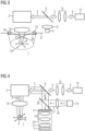
- FIG 1 An exemplary embodiment of a device according to the improved concept is shown schematically.
- the device is used for the additive manufacturing of a workpiece, for example from a powder bed 1.
- the powder bed 1 can be arranged in a working space which is, for example, completely or partially enclosed by a housing (not shown).
- a heating source 14 is configured to generate a melt beam 3, in particular a laser beam or electron beam.
- the device includes a scanning unit 2, also called a scanning unit, which can receive the melt beam 3 on an input side facing the heating source 14.
- a scanning unit 2 also called a scanning unit
- An optical system 15 for beam shaping the melt beam 3 can optionally be arranged between the scanning unit 2 and the heating source 14.
- the device further includes a focusing unit 16, which is designed, for example, as an F-theta lens or contains one, and which is arranged on the output side of the scanning unit 2, i.e., in particular, between the scanning unit 2 and the powder bed 1.
- the focusing unit 16 can focus the melt jet 3 and direct it onto a writing point 4 on a surface of the powder bed 1 or the workpiece.
- the scanning unit 2 can be controlled, for example, by a control unit 6 of the device, to deflect the melt jet 3 as required for the production of the workpiece according to the order.
- the device also has an imaging unit 7, by means of which a partial area 8 of the powder bed 1, in the example shown the FIG 1 a partial area 8 around the writing point 4 can be imaged onto a detector 5 of the device.
- the detector 5 is designed as a spatially resolved detector with an array of light-sensitive sensors and can For example, it may be part of a camera.
- the imaging unit may, for example, include a beam splitter 9 arranged between the heating source 14 and the scanning unit 2. Light emitted from the partial region 8 and incident on the beam splitter 9 via the imaging unit 2 can be decoupled by the beam splitter 9 and directed onto the detector 5.
- the imaging unit 7 includes a lens 10 for beam shaping and/or focusing the coupled-out light on the detector 5.
- the imaging unit may comprise a filter 17 which preferably allows light to pass to which the detector 5 is sensitive and preferably blocks or attenuates light corresponding to a wavelength or wavelength range of the melt jet 3.
- the device can also have an illumination unit 11, in particular with a light source 13 and an optional beam-shaping optics 18.
- the illumination unit 11 is arranged and configured such that it can couple an illumination light 12 into the beam path of the melt jet 3 and thereby illuminate an illumination region on the powder bed 1 which at least partially includes the partial region 8.
- the imaging unit 7 or the illumination device 11 has a further beam splitter 26, which can first couple the illumination light 12 into a beam path of the light for imaging the partial area 8 onto the detector 5 and then, for example, via the beam splitter 9 into the beam path of the melt beam 3.
- both the partial area and the illumination area are directly coupled to the melt beam 3 in such a way that the scanning unit 2, in the event of a deflection of the melt beam 3 also synchronously deflects the illumination light 12 and the imaging light for imaging the partial area 8 onto the detector 5.
- FIG 2 a schematic representation of another exemplary embodiment of the device is shown.
- the design of the FIG 2 differs from that in the FIG 1 at least in that the illumination device 11 has further light sources 19, 19' that can couple the illumination light 12 directly into the beam path of the melting beam 3.
- the light sources 19, 19' are arranged, for example, around the beam path of the melting beam 3, for example on the beam splitter 9.
- the further beam splitter 26 can be omitted.
- FIG 3 a schematic representation of another exemplary embodiment of the device is shown.
- the design of the FIG 3 differs from those of the FIG 2 in particular, in that the additional light sources 19, 19' are arranged between the scanning unit 2 and the powder bed 1, in particular outside a workspace housing 27 within which the powder bed 1 is arranged.
- the additional light sources 19, 19' can, for example, direct the illumination light 12 directly onto the powder bed 1 through a cover window 28 of the workspace housing 27.
- An illumination area 24 can thus cover large parts or the entire powder bed 1 and the workpiece.
- the devices as they are in FIG 1 to FIG 3 , or also in FIG 4 to FIG 6 , can be used in particular for monitoring additive manufacturing and/or for process control of additive manufacturing according to respective methods according to the improved concept.
- the device according to the improved concept can perform process monitoring and process control in real time or near real time, in particular online.
- the imaging unit 11 which in particular contains imaging optics, is used to image the partial area 8, in particular the partial area 8 around the writing point 4, onto the spatially resolved detector 5.
- a pixel size can be achieved that is selected to be at least half as large as a resolution limit determined according to a Rayleigh or Sparrow criterion.
- a detector sensor size 10 megapixels and an average edge length of approximately 3000 pixels results in a detection area of over 30 mm edge length, i.e., an area of approximately 10 cm2 .
- the grain size of a powder for production in particular a metal powder, is, for example, in the range of approximately 10 ⁇ m.
- Other parameterizations are possible, for example, to obtain optimal imaging conditions in other specific applications.
- the light for imaging on the detector can be branched off from a beam path of the melt beam 3 by means of a beam splitter 9.
- the beam splitter 9 By arranging the beam splitter 9 between the heating source 14 and the scanning unit 2, the optical system always remains centered to the melt beam 3, in particular regardless of a deflection state a deflection mirror of the scanning unit 2 during the respective writing process.
- the location of the melt beam 3 can advantageously be located in a central area of the detector image, since this is where the writing process takes place and, for example, in the case of SLM, a melt pool is formed.
- the optional illumination system allows for particularly high-quality images to be captured.
- the illumination wavelength can be adapted to the sensitivity range of detector 5.
- the lighting unit is advantageously designed so that it can be switched on and off, so that, on the one hand, when switched on, for example, the entire field of view can be illuminated with basic lighting. Since a writing area and the areas surrounding it in the powder bed 1 or on the workpiece can also radiate in the infrared or visible spectral range due to a correspondingly elevated temperature, these areas can appear even brighter in the image. On the other hand, when the lighting unit 11 is switched off, apart from possible ambient light, only the self-illumination of the writing area and its surroundings can be seen. This area can then be recorded thermographically, for example, and its temperature evaluated.
- the partial area 8 thus lights up due to the energy introduced by the melting beam 3, because the heated material partially radiates the energy thermally.
- the brightness with which an object appears in the image in the detector 5 correlates with the temperature of this object, for example, of the partial area 8.
- This assignment of brightness to recording parameters, such as exposure time or gain, or to settings of an imaging optics, such as aperture or diaphragm, or material parameters, such as material, grain size, emissivity of the powder or of the corresponding fused material can be determined using a thermometric Calibration and then used for measurement, especially thermometric measurement.
- thermometric measurement makes it possible, in particular, to directly convert a brightness distribution in the image into a temperature distribution of the workpiece, so that a thermal profile of the workpiece can be detected and measured in an area around the melt jet 3, in particular in the partial area 8, using a device according to the improved concept.
- the emissivity of the powder differs from that of the sintered or molten material, it may be advantageous and useful to first analyze the image using image processing before applying the thermometric calibration to determine which image areas are covered with powder and which with sintered or molten material. The respective thermal calibration can then be performed, for example, based on the material types present.
- sintered material may occur at the edge of a writing path, for example, if the energy or temperature was not sufficient for complete melting and the material was only partially melted, thus sintering neighboring powder particles.
- a polarization-sensitive camera can be understood here as a camera that either has a polarization-sensitive camera chip with a corresponding structure.
- a camera can be provided in which a polarization filter 17 is arranged in front of a conventional camera chip, preferably on a beam path between beam splitter 9 and camera chip, i.e. detector 5. This polarization filter 17 has either been introduced into the beam path or can be variable in its transmission direction, so that the polarization state of the light from the object area can be measured with different settings of the polarization filter 17.
- a reflection behavior of the partial area 8 can also be used. For example, if one has structured illumination that contains two grid patterns that are rotated relative to each other by a fixed angle, for example 45°, and one of the grid patterns is projected sharply onto a surface of the powder bed 1 or the workpiece, while the other pattern is emitted diffusely, a material type, for example powdery or molten, can be identified based on the reflection quality using deflectometry or fringe projection and the respective degree of reflection or contrast.
- the imaging of the partial area 8 on the detector 5 can be carried out, for example, with a camera that contains the detector 5.
- the image is advantageous for the image to be recorded with the camera coupled to the melting beam 3 or the imaging unit 2 in order to record an image with only one flash of light, so that a movement of the melting beam 3 and thus also of the observation beam path due to the beam deflection in the imaging unit 2 does not result in smearing of the image content or in motion blurring.
- motion blurring can be compensated using well-known motion deblurring methods. This requires a relative motion between sub-area 8 and the camera to be known, so that at least larger structures can be more easily recognized and displayed with better contrast.
- the detector 5 and/or the lens 10 can be equipped with one or more actuators (not shown) so that the lens 10 and/or the detector 5 or the camera can be tracked according to a movement of the writing beam 3.
- a current position of the imaging unit 2 or a deflection mirror of the imaging unit 2 or a position of the writing point 4 can be known so that the movement information can be determined from a corresponding location signal.
- the detector 5 can be designed as a camera sensor that is movable relative to the lens 10 in a direction within a detector plane.
- a mobility perpendicular to the detector plane can also be advantageous, for example, to compensate for defocusing by the scanning system 2 or the F-theta of the focusing unit 16, for example, at the edges of the field of view. With tracking of the detector 5 perpendicular The focus can then be adjusted as best as possible to the detector plane.
- the detector can, for example, be equipped with a gimbal suspension with an effective pivot point in the center of the detector 5. This can be advantageous because it also allows for compensation of an inclination of the partial area 5 relative to the optical axis across the working range of the device. If the distance of the pivot point from the detector surface is particularly advantageously selected to match a magnification ratio of the focusing unit 16 or a deflection by the scanning unit 2 or magnification by the imaging optics, complete correction of displacement, inclination, and focus is possible with only three drives for the detector 5.
- a tilt of the image can also be achieved by decentering at least one lens or lens group in the imaging optics, or special correction elements can be provided for this purpose for the displacement and correction of possible imaging errors, such as astigmatism or spherical aberration.
- These can be designed, for example, with a plate in the imaging optics between beam splitter 9 and detector 5 that can be tilted about two axes or rotated about an optical axis and a plate that can be tilted perpendicular to the optical axis, in particular a plane-parallel plate.
- the tiltable plate can at least largely correct both a focus position and the imaging errors caused by the possibly inclined beam path of the melt beam 3 to the writing location 4.
- two wedge plates arranged in opposite directions can be provided instead of the tilting plate, which, for example, can be rotated against each other by an axis parallel to the vertex axis of the wedge plates.
- This also allows for adjustable beam deflection of the melt beam 3, which can compensate for the inclination of the imaging beam with respect to the partial area 8 or the powder bed 1 and allows the image on the detector 5 to be sharply focused over the entire area.
- thermal radiation of sub-area 8 can be captured using cameras in the near-infrared or visible spectral range.
- cameras with sensitivities in the infrared range or thermoelectric cameras for near-infrared and/or far-infrared can be used.
- the filter 17 can include a dichroic filter or a narrowband blocking filter for a wavelength of the melting beam 3, in particular one adapted to a wavelength range of the melting beam 3.
- a corresponding filter can be arranged in the beam splitter 9. If the melting beam 3 contains polarized light, the polarization can also be used for efficient filtering.
- the device according to FIG 1 to FIG 6 As described, it can also be detected in areas adjacent to the current writing point 4, particularly from previously written paths or even in the powder bed. With knowledge of the temperature in the workpiece, the parameters of the current writing process can then be adjusted so that, for example, the most uniform temperature profile possible is achieved during writing. This can minimize thermal stresses that can arise from local heating in the workpiece during the manufacturing process.
- Devices according to the improved concept according to FIG 1 to FIG 6 allow a planar image of the partial area 8 around the writing point 4. Disturbances such as defects, voids, excess material, splashes, and so on, especially immediately in front of the writing point 4 and also in an overlapping area, can be detected.
- a thermal two-dimensional image can be generated, in which a temperature profile in sub-area 8 can be measured. Accordingly, an adapted control of a melt jet power can be achieved for the most homogeneous temperature control possible at the writing point 4 and in sub-area 8.
- the topography of sub-area 8 can also be detected using three-dimensional methods such as fringe projection or deflectometry.
- a camera with the detector 5 can also be directed directly into the workspace and, for example, follow the melt jet 3 or the writing point 4 using its own kinematics.
- the melt jet 3 can be followed in this case using an image processing-based approach. Motion blurring can also be avoided with appropriate control.
- FIG 4 schematically shows another exemplary embodiment of a device according to the improved concept.
- the basic structure of the device corresponds to that shown in FIG 1 shown.
- the device according to FIG 4 includes a light field camera 20, also known as a plenoptic or multi-aperture camera.
- the light field camera 20 includes the detector 5, the lens 10, and the optional filter 17.
- the light field camera 20 includes, for example, an array of microlenses 21 arranged between the objective lens 10 and the detector 5.
- the microlenses 21 divide a corresponding imaging beam path into subapertures. For each of these subapertures, a separate image is then created on the detector 5, each with slightly different viewing angles due to the spatial offset of the microlens 21. From the slightly different partial images, a spatial structure of the partial area 8 can be calculated using triangulation methods, resulting in two-and-a-half-dimensional or three-dimensional images.
- different focal lengths can be used for different lenses of the microlenses 21. Lenses with two, three, or more different focal lengths can be used for this purpose.
- the light field camera 20 can be used to avoid asymmetric pre-embossing at edges due to the specified triangulation direction and the structure of the hardware.
- the light field camera 20 can monitor the entire powder bed 1 and workpiece in a single shot.
- the setting of the light field camera 20 can then remain fixed or constant during production.
- the light field camera 20 can be specifically directed at regions of the powder bed 1, in particular at the partial region 8, and inspect them with a correspondingly higher resolution.
- the imaging beam for the light field camera 20 can be guided at least partially coaxially with the melt jet 3 and can strike the powder bed 1 coaxially with the melt jet 3. This is the case in the exemplary embodiment of the FIG 4 the case.
- an optical axis of the imaging optics tilts according to the pivoting movements, and consequently, the sharply imaged object plane of the optics, which is perpendicular to the optical axis, also tilts.
- the image sharpness of the image changes along the direction of the incidence plane of the imaging beam.
- the light field camera 20, particularly in the version with microlenses 21 of different focal lengths can sharply image a much larger depth of field, this blurring can be fully or partially compensated.
- the image on the detector 5 of the light field camera 20 can be digitally refocused. This results in a sharp image being calculated for an image plane oblique to the optical axis, which is conjugated to the tilted object plane via the optics, depending on the existing tilt position of the optical axis relative to a workpiece surface or a surface of the powder bed 1.
- a three-dimensional point cloud can be determined from measurement data of the light field camera 20, which can then represent the tilted object plane, in particular together with a topography of individual features in the partial area 8, such as elevations or depressions, for example, material splashes on the powder bed 1 or holes in the powder bed 1.
- the data can therefore be represented in a reference coordinate system, preferably a workpiece coordinate system or machine coordinate system.
- Images from the light field camera 20 can, for example, be metrically calibrated for a fixed focus and zoom setting of the imaging lens. With metrically calibrated images, stitching can be performed more effectively because the distortions from the camera image can be minimized.
- the effect of the optics for different beam tilt angles and associated effective beam axes can also be determined via simulation and then taken into account, for example, in an evaluation. Combinations of measurement and simulation are also possible, for example, to take advantage of the time savings of simulation while still capturing a comparison with the actual system as completely as possible.
- the light field camera 20 can be configured, for example, as a color camera or a black-and-white camera with a sensitivity range, for example, in the ultraviolet, visible, infrared, near-infrared, mid-infrared, and/or far-infrared spectral range.
- a version with a silicon detector may be advantageous, particularly with a sensitivity range of approximately 400 to 1100 nm.
- a direction-dependent three-dimensional or two-and-a-half-dimensional detection of the partial area 8 can be carried out.
- the depth of field can, for example, be increased in order to digitally compensate for tilting of the imaging beam.
- distance control from a writing head to the workpiece surface or to the powder bed 1 can be carried out approximately in real time.
- thermal recording and calibration please refer to the explanations for FIG 1 to FIG 3 referred to.
- FIG 5 A schematic representation of another exemplary embodiment of a device according to the improved concept is shown.
- a basic structure of the device corresponds to that of the device according to FIG 1 to FIG 4 .
- the device includes a camera 25, which may, for example, correspond to the light field camera 20 and/or the detector 5 according to FIG 1 to FIG 3 may contain. Also shown is an evaluation unit 23 coupled to the camera 25.
- the evaluation unit 23 can, for example, detect detector signals generated by the camera 25 or the detector 5 and, based thereon, control a manufacturing process for additive manufacturing.
- the device also includes a spectroscope or spectrometer 22, which can detect light emanating from the partial area 8 and, based thereon, generate spectral signals and, for example, supply them to the evaluation unit 23.
- a spectroscope or spectrometer 22 which can detect light emanating from the partial area 8 and, based thereon, generate spectral signals and, for example, supply them to the evaluation unit 23.
- FIG 6 shows a further schematic representation of an exemplary embodiment of a device according to the improved concept.
- the device of FIG 6 largely corresponds to the device from FIG 5 .
- the beam splitter 9 is provided to decouple light from the beam path of the melt jet 3 and to direct it to the further beam splitter 26, which directs light to the camera 25 and to the spectroscope or spectrometer 22, are in FIG 6 both beam splitters 9 and 26 one after the other in the beam path of the melt beam 3 arranged and independently couple light for the camera 25 or the spectroscope or spectrometer 22 from the beam path of the melt jet 3.
- a device according to FIG 5 or FIG6 can be used in particular to carry out a process control method according to the improved concept, in particular as described below with regard to the FIG 7 to FIG 9 is explained.
- FIG 7 A flowchart schematically depicts a method for process control according to the improved concept.
- a step 601 detector signals from detector 5, in particular containing two-dimensional, two-and-a-half-dimensional, or three-dimensional information about subregion 8, are detected and transmitted, for example, to evaluation unit 23.
- the evaluation unit 23 determines, for example, a topography of the writing location 4 or the sub-area 8.
- the information from 601 is optionally used in a step 603 to create a thermal profile of the writing location 5 or the partial area 8, for example by means of the evaluation unit 23.
- spectral signals can be transmitted from the spectroscope or spectrometer 22 to the evaluation unit 23.
- the spectral signals can be taken into account, for example, when determining the thermal profile.
- the evaluation unit 23 uses the spectral signals to determine information about possible contamination in the sub-area 8.
- step 606 sound signals or acoustic signals, in particular structure-borne sound signals, are received from a Sound sensor of the device, which is coupled to the workpiece, is transmitted to the evaluation unit 23.
- the evaluation unit 23 can determine information about the occurrence of cracks, stresses or relaxations in the workpiece based on the sound data.
- Additional sensors or measuring devices can optionally acquire additional measured variables in a step 608 and transmit them to the evaluation unit 23.
- the evaluation unit 23 can, for example, generate derived process information based on the additional measured variables.
- the information, profiles, topographies, and so on generated in steps 602, 603, 605, 607, or 609 can be used, for example, in a step 610 for process control, in particular for controlling a writing process for manufacturing the workpiece by the device.
- the evaluation unit 23 can calculate optimized writing data with current process information based on the information and data thus acquired. Deviations of a writing path or the writing point 4 from target values can be minimized or compensated based on the optimized writing data.
- the evaluation unit 23 can control the heating source 14 and/or the scanning unit to control the writing process.
- the evaluation unit can, for example, determine information or status information on potential deviations or errors and output it, for example, to a user of the device, for example via a user interface or a display device.
- the evaluation unit 23 can, for example, also abort the writing process in step 610. In particular, the evaluation unit 23 can deactivate the heating source 14 for this purpose.
- the evaluation unit 23 can, for example in a step 611, also acquire target data or layer data for the production of the workpiece or, for example, CAD data and take these into account in the required calculations.
- the evaluation unit 23 can directly or indirectly control various system components of the device in order to control the process.
- the evaluation unit 23 can control a coating unit in order to determine or adjust a layer thickness for a coating after the actual additive manufacturing of the workpiece.
- the evaluation unit 23 can, for example, control the heating source 14 in such a way that the energy of the melt jet 3 is changed. Alternatively or additionally, the evaluation unit 23 can control the scanning unit 2 to compensate or minimize the deviations accordingly. Alternatively or additionally, the evaluation unit 23 can also control the focusing unit 16, in particular the F-theta lens, to correct a focus.
- FIG 8 A flowchart of a further exemplary embodiment of a method for process control according to the improved concept is shown.
- a thermal image for example of a melting area or the writing location or the partial area 8 is transmitted to the evaluation unit 23.
- a surface image in particular a two-dimensional and/or two-and-a-half-dimensional and/or three-dimensional surface image of the powder bed 1 or the partial area 8 is transmitted to the evaluation unit 23.
- the evaluation unit 23 can, for example, determine a temperature profile or isotherms based on the thermal image.
- the evaluation unit 23 can, for example, determine topographic information of the partial area 8 and, for example, detect holes, splashes, other structures or powder residues.
- the evaluation unit 23 can, for example, determine a required or adjustable energy quantity of the melt jet 3, for example from the temperature profile or from the surface image of the partial region 8. Alternatively or additionally, the evaluation unit 23 can also determine an operating mode of the heating source 14, for example to optimize a temperature profile before writing or, depending on the location, alternating with the writing.
- the evaluation unit 23 can, for example, control the heating source 14 and/or the scanning unit 2 and/or the focusing unit 16, for example to adapt the manufacturing process.
- the evaluation unit can switch between different operating modes of the device, for example, between a heating mode and a writing mode.
- step 705 can optionally be supported, for example, by CAD data or layer data or target data from a step 704.
- a flowchart of another exemplary embodiment of a method for process control according to the improved concept is shown.
- a step 801 corresponds to a step 701 in FIG 8 .
- a step 802 corresponds to a step 702 in FIG 8 .
- further data such as sensor data, further measured variables, sound signals and/or spectral signals can be transmitted to the evaluation unit 23.
- a step 804 corresponds to a step 704 in FIG 8 .
- the evaluation unit 23 can perform steps, in particular calculation steps, for thermal process control.
- the evaluation unit 23 can dynamically determine one or more process parameters.
- the evaluation unit 23 can, for example, activate one of several operating modes of the device, for example a write mode, a write and heat mode, or a heat mode.
- a step 806 the workpiece can then be manufactured.
- a quality inspection of the workpiece can be performed.
- a step 808 for example, deviations of the actual values of the workpiece from the target values and/or defects in the workpiece can be determined.
- step 809 for example, data from measurements taken during production can be provided.
- step 810 production parameters can be provided.
- the evaluation unit can, for example, optimize the model for dynamically determining process parameters based on the deviations or defects determined in step 808 and optionally on the data from 809 and the parameters from 810.
- structural elements and/or morphologies can be determined.
- the model can be adapted, in particular, on a component-specific or area-specific basis.
- the optimized adapted model can be taken into account in the thermal process control, for example for future production of another workpiece.
- the signals of further, previously unmentioned sensors or also control or positioning signals or information are included in a processing of the respective measurement data in the sense of process control.
- Process control based on the improved concept uses this information about the writing process or the workpiece itself to regulate the writing process in such a way that the dimensional tolerances of the workpiece are minimized and, for example, thermal loads and/or temperature gradients in the component are minimized or kept as stable and controlled as possible. This can advantageously minimize stresses in the workpiece.
- Measurements with additional sensors also serve to more comprehensively capture the writing process and other parameters and variables that influence the quality of the workpiece. For example, sound measurement is described here.
- Process control according to the improved concept allows for a more precise use of the available information to improve the production result.
- the process control can take over geometric information from the images of subarea 8 in order to monitor and control a focus position or height positioning in the process.
- the height control can also indirectly influence, for example, the depth effect of the writing process. For example, more complex structures, such as protrusions or undercuts, which are typical in workpieces can be manufactured with greater precision.
- the layer thickness of the next layer or layer can be adjusted so that, for example, defects in the current layer can be reliably filled, or protruding parts do not interfere with the coating process or cause disruptions.
- defects in the current layer can be reliably filled, or protruding parts do not interfere with the coating process or cause disruptions.
- defects can build up over several layers before causing process disruptions.
- Such defects can then be intercepted with early correction or countermeasures, preventing process disruptions.
- a heating power or energy input or laser power can be controlled, particularly of the melting beam 3, so that the writing point 4 has a desired lateral extent. For example, this allows controlled processing of writing points 4 of different sizes within the workpiece and within a layer in order to optimize the production result.
- the geometric guidance of the melt jet 3 can be monitored in such a way that geometric distortions in the manufacturing process can be corrected online.
- Options for geometric melt jet guidance via a two-dimensional or three-dimensional detection of the partial area 8 are described.
- the position and size of structures or adjacent writing paths can be determined and taken into account for process control.
- the process control also uses thermal or spectroscopic information and signals, for example, to achieve the most homogeneous or stable temperature in the writing area, to minimize thermal gradients, and/or to create a depth profile for local heat input and dissipation. Furthermore, Material changes can be detected, such as oxidation from previous overheating. Finally, foreign materials can also be detected.
- Additional sensor information such as sound signals, can be taken into account, for example, to detect crack formation or splashes and/or to determine other production-relevant or process-relevant parameters.
- the process control uses the above information and, if necessary, further information from machines and/or material-specific specifications or even geometry information, for example from CAD data, in order to enable optimized process control with deterministic and/or learned evaluations and/or modeling.
- information collected from the manufacturing process can be analyzed in detail for the entire workpiece or for parts of a workpiece, for example, to further optimize the process control, for example for other similar parts or for modular or recurring structural elements in new or comparable workpieces.
- An analysis concerning, for example, crack formation or material changes or other quality criteria or material contamination can be used in addition to the analysis of purely geometric deviations to stop or abort an ongoing production order as soon as it is expected or recognized that the manufactured workpiece can no longer meet existing quality criteria.
- a single- or multi-stage heating process can also be carried out according to the process control, for example, whereby only the workpiece is successively heated with increasing power by means of the melting jet 3 until a stable writing process, favorable temperature distribution and corresponding cooling behavior are achieved.
- This method can also be used preferentially when hybrid manufacturing processes are used, for example, when an additional part is to be added to an existing part or semi-finished product using additive manufacturing or manufactured in a stable material composite. Such scenarios can arise in repair and maintenance, where areas damaged by wear or removed during the repair process need to be reproduced.
Landscapes
- Engineering & Computer Science (AREA)
- Chemical & Material Sciences (AREA)
- Materials Engineering (AREA)
- Manufacturing & Machinery (AREA)
- Physics & Mathematics (AREA)
- Optics & Photonics (AREA)
- Mechanical Engineering (AREA)
- Toxicology (AREA)
- Health & Medical Sciences (AREA)
- General Health & Medical Sciences (AREA)
- Plasma & Fusion (AREA)
- Automation & Control Theory (AREA)
- Analytical Chemistry (AREA)
- Powder Metallurgy (AREA)
- Laser Beam Processing (AREA)
Claims (14)
- Dispositif pour la fabrication additive d'une pièce à usiner, le dispositif comprenant :- une unité de balayage (2) qui est conçue afin de diriger un faisceau de fusion (3) vers un point d'écriture (4) sur une surface d'écriture (1) ;- une caméra à champ lumineux (20) dotée d'un détecteur optique à résolution locale (5) ;- une unité d'imagerie (7) qui est conçue et agencée afin d'imager une zone partielle (8) de la surface d'écriture (1) au moins en deux dimensions au moyen du détecteur (5), dans laquelle le détecteur (5) est conçu afin de générer au moins un signal de détecteur sur la base de l'image de la zone partielle (8) ;- une unité de commande (6) qui est conçue afin de commander le dispositif permettant de modifier une position de la zone partielle (8) pendant la fabrication ; et- une unité d'évaluation (23) pour l'évaluation et/ou le traitement du au moins un signal de détecteur.
- Dispositif selon la revendication 1, dans lequel l'unité d'imagerie (2) présente un séparateur de faisceau (9) qui est agencé sur un côté d'entrée de l'unité de balayage (2) dans un trajet de faisceau du faisceau de fusion (3).
- Dispositif selon l'une quelconque des revendications 1 ou 2, dans lequel l'unité d'imagerie (2) contient un actionneur qui est conçu afin de, par l'intermédiaire de l'unité de balayage (2), suivre le détecteur (5) et/ou un objectif (10) de l'unité d'imagerie (7) en fonction d'une déviation du faisceau de fusion (3) pour l'imagerie de la zone partielle (8).
- Dispositif selon l'une quelconque des revendications 1 à 3, comprenant en outre un dispositif d'éclairage (11) qui est conçu afin d'éclairer au moins partiellement la zone partielle (8).
- Dispositif selon la revendication 4, dans lequel au moins une source de lumière (13) du dispositif d'éclairage (11) est agencée et conçue afin de coupler la lumière pour l'éclairage sur un côté d'entrée de l'unité de balayage (2) dans un trajet de faisceau du faisceau de fusion (3).
- Dispositif selon l'une quelconque des revendications 4 ou 5, dans lequel au moins une source de lumière supplémentaire (19, 19') du dispositif d'éclairage (11) est agencée entre l'unité de balayage (2) et la surface d'écriture (1).
- Dispositif selon l'une quelconque des revendications 1 à 6, dans lequel l'unité d'évaluation (23) est conçue afin de déterminer au moins une caractéristique thermique de la zone partielle (8) sur la base du au moins un signal de détecteur.
- Dispositif selon l'une quelconque des revendications 1 à 7, dans lequel l'unité d'évaluation (23) est conçue afin de déterminer une information topographique de la zone partielle (8) sur la base du au moins un signal de détecteur.
- Dispositif selon l'une quelconque des revendications 1 à 8, dans lequel l'unité d'évaluation (2) est conçue afin de déterminer une position de déviation du faisceau de fusion (3) sur la base du au moins un signal de détecteur.
- Procédé selon l'une quelconque des revendications 1 à 9,- présente un spectroscope et/ou un spectromètre (22), qui est conçu et agencé afin de détecter de la lumière émanant de la surface d'écriture (1) et de générer un signal de spectromètre sur cette base, qui contient des informations spectrométriques ou spectroscopiques sur la lumière ; et/ou- comprend un ou plusieurs capteurs acoustiques, le capteur acoustique pouvant être couplé à la pièce à usiner.
- Procédé de fabrication additive d'une pièce à usiner, dans lequel un faisceau de fusion (3) est dirigé vers un point d'écriture (4) sur une surface d'écriture (1) pour la fabrication, le procédé comprenant les étapes suivantes consistant à :- capturer une image à résolution spatiale d'au moins deux dimensions d'une zone partielle (8) de la surface d'écriture (1) au moyen d'un détecteur à résolution spatiale (5) d'une caméra à champ lumineux (20), une position de la zone partielle (8) étant modifiée pendant la fabrication ;- générer au moins un signal de détecteur sur la base de l'image au moyen du détecteur (5) ;- surveiller la fabrication sur la base du au moins un signal de détecteur ; et- évaluer et/ou traiter le au moins un signal de détecteur.
- Procédé de fabrication additive d'une pièce à usiner selon la revendication 11, comprenant en outre les étapes suivantes consistant à :- déterminer au moins une caractéristique thermique de la zone partielle (8) sur la base du au moins un signal de détecteur ; et- définir ou modifier au moins un paramètre de processus pour la fabrication en fonction de la au moins une caractéristique thermique.
- Procédé selon la revendication 12, dans lequel- un signal acoustique est détecté par un capteur acoustique couplé à la pièce à usiner et la définition ou la modification du au moins un paramètre de processus est effectuée en fonction du signal acoustique ; et/ou- un signal de spectromètre est généré sur la base de la lumière émise par la surface d'écriture (1) et la définition ou la modification du au moins un paramètre de processus est effectué en fonction du signal de spectromètre.
- Programme informatique avec des instructions qui, lors de l'exécution du programme informatique par un système informatique, amènent un dispositif selon l'une quelconque des revendications 1 à 10 à exécuter un procédé selon l'une quelconque des revendications 11 à 13.
Applications Claiming Priority (2)
| Application Number | Priority Date | Filing Date | Title |
|---|---|---|---|
| EP19158124.8A EP3698947A1 (fr) | 2019-02-19 | 2019-02-19 | Surveillance et régulation du processus d'une fabrication additive d'une pièce à usiner |
| PCT/EP2020/053683 WO2020169433A1 (fr) | 2019-02-19 | 2020-02-13 | Surveillance et régulation de processus d'une fabrication additive d'une pièce |
Publications (3)
| Publication Number | Publication Date |
|---|---|
| EP3911498A1 EP3911498A1 (fr) | 2021-11-24 |
| EP3911498C0 EP3911498C0 (fr) | 2025-04-02 |
| EP3911498B1 true EP3911498B1 (fr) | 2025-04-02 |
Family
ID=65529299
Family Applications (2)
| Application Number | Title | Priority Date | Filing Date |
|---|---|---|---|
| EP19158124.8A Pending EP3698947A1 (fr) | 2019-02-19 | 2019-02-19 | Surveillance et régulation du processus d'une fabrication additive d'une pièce à usiner |
| EP20706975.8A Active EP3911498B1 (fr) | 2019-02-19 | 2020-02-13 | Surveillance et régulation du processus d'une fabrication additive d'une pièce à usiner |
Family Applications Before (1)
| Application Number | Title | Priority Date | Filing Date |
|---|---|---|---|
| EP19158124.8A Pending EP3698947A1 (fr) | 2019-02-19 | 2019-02-19 | Surveillance et régulation du processus d'une fabrication additive d'une pièce à usiner |
Country Status (4)
| Country | Link |
|---|---|
| US (1) | US12358214B2 (fr) |
| EP (2) | EP3698947A1 (fr) |
| CN (1) | CN113784832A (fr) |
| WO (1) | WO2020169433A1 (fr) |
Families Citing this family (5)
| Publication number | Priority date | Publication date | Assignee | Title |
|---|---|---|---|---|
| FR3112602B1 (fr) * | 2020-07-20 | 2023-04-07 | Office National Detudes Rech Aerospatiales | Dispositif de contrôle pour fabrication d’une piece avec ajout de matiere |
| DE102021104440A1 (de) * | 2021-02-24 | 2022-08-25 | Fraunhofer-Gesellschaft zur Förderung der angewandten Forschung eingetragener Verein | Messsystem für ein Fertigungssystem zur in-situ Erfassung einer Eigenschaft und Verfahren |
| US11954842B2 (en) * | 2021-09-06 | 2024-04-09 | Huaneng Nanjing Jinling Power Generation Co., Ltd. | Powder leakage monitoring device and powder leakage monitoring method |
| TWI811926B (zh) * | 2021-12-28 | 2023-08-11 | 國家中山科學研究院 | 積層製造鋪粉表面監測系統 |
| DE102022101379B4 (de) | 2022-01-21 | 2023-08-24 | Precitec Gmbh & Co. Kg | Laserbearbeitungskopf und laserbearbeitungssystem mit entsprechendem laserbearbeitungskopf |
Family Cites Families (11)
| Publication number | Priority date | Publication date | Assignee | Title |
|---|---|---|---|---|
| WO2007147221A1 (fr) * | 2006-06-20 | 2007-12-27 | Katholieke Universiteit Leuven | Procédure et appareil pour la surveillance in situ et la commande par rétroaction d'un traitement sélectif de poudre laser |
| DE102012221218A1 (de) * | 2011-11-22 | 2013-05-23 | Leibniz-Institut Für Festkörper- Und Werkstoffforschung Dresden E.V. | Vorrichtung zur Qualitätssicherung von mittels Laserstrahlbearbeitung hergestellten Produkten |
| DE102013008085B4 (de) * | 2013-05-10 | 2017-02-16 | Fraunhofer-Gesellschaft zur Förderung der angewandten Forschung e.V. | Verfahren und Vorrichtung zum Fügen von Werkstücken mit einem Bearbeitungsstrahl |
| DE102015011013B4 (de) | 2014-08-22 | 2023-05-04 | Sigma Additive Solutions, Inc. | Verfahren zur Überwachung von generativen Fertigungsprozessen |
| US10786948B2 (en) * | 2014-11-18 | 2020-09-29 | Sigma Labs, Inc. | Multi-sensor quality inference and control for additive manufacturing processes |
| DE102015000102A1 (de) | 2015-01-14 | 2016-07-14 | Cl Schutzrechtsverwaltungs Gmbh | Vorrichtung zur generativen Herstellung dreidimensionaler Bauteile |
| DE102015207834A1 (de) * | 2015-04-28 | 2016-11-03 | Siemens Aktiengesellschaft | Bearbeitungsmaschine für ein mit einem Laserstrahl durchzuführendes Produktionsverfahren und Verfahren zu deren Betrieb |
| DE102016001355B4 (de) * | 2016-02-08 | 2022-03-24 | Primes GmbH Meßtechnik für die Produktion mit Laserstrahlung | Verfahren und Vorrichtung zur Analyse von Laserstrahlen in Anlagen für generative Fertigung |
| DE102016011801A1 (de) | 2016-09-30 | 2018-04-05 | Eos Gmbh Electro Optical Systems | Verfahren zum Kalibrieren einer Vorrichtung zum Herstellen eines dreidimensionalen Objekts und zum Durchführen des Verfahrens ausgebildete Vorrichtung |
| US11268933B2 (en) * | 2016-10-27 | 2022-03-08 | Jentek Sensors, Inc. | In-process quality assessment for additive manufacturing |
| US10710307B2 (en) * | 2017-08-11 | 2020-07-14 | Applied Materials, Inc. | Temperature control for additive manufacturing |
-
2019
- 2019-02-19 EP EP19158124.8A patent/EP3698947A1/fr active Pending
-
2020
- 2020-02-13 EP EP20706975.8A patent/EP3911498B1/fr active Active
- 2020-02-13 WO PCT/EP2020/053683 patent/WO2020169433A1/fr not_active Ceased
- 2020-02-13 US US17/432,316 patent/US12358214B2/en active Active
- 2020-02-13 CN CN202080029917.8A patent/CN113784832A/zh active Pending
Also Published As
| Publication number | Publication date |
|---|---|
| CN113784832A (zh) | 2021-12-10 |
| WO2020169433A1 (fr) | 2020-08-27 |
| US12358214B2 (en) | 2025-07-15 |
| EP3698947A1 (fr) | 2020-08-26 |
| EP3911498C0 (fr) | 2025-04-02 |
| US20220168840A1 (en) | 2022-06-02 |
| EP3911498A1 (fr) | 2021-11-24 |
Similar Documents
| Publication | Publication Date | Title |
|---|---|---|
| EP3911498B1 (fr) | Surveillance et régulation du processus d'une fabrication additive d'une pièce à usiner | |
| US20230202120A1 (en) | Method and System for Quality Assurance and Control of Additive Manufacturing Process | |
| EP3003633B1 (fr) | Dispositif et procédé pour déterminer la position focale d'un faisceau d'énergie à haute densité | |
| DE112018001597B4 (de) | Systeme und Verfahren zum Messen abgestrahlter thermischer Energie während der Ausführung einer additiven Fertigung | |
| EP3581884B1 (fr) | Fabrication additive avec surveillance du procédé par mesure optique | |
| DE102011078276C5 (de) | Verfahren zum Erkennen von Fehlern während eines Laser-Bearbeitungsprozesses sowie Laser-Bearbeitungsvorrichtung | |
| US20170368640A1 (en) | Device for the additive production of three-dimensional components | |
| DE112019000498T5 (de) | Systeme und Verfahren zum Messen abgestrahlter thermischer Energie während der Ausführung einer additiven Fertigung | |
| DE102013017795C5 (de) | Prozessüberwachungsverfahren und -vorrichtung | |
| US20160114431A1 (en) | System and methods for real-time enhancement of build parameters of a component | |
| EP1693141B1 (fr) | Dispositif et procédé de mesure localisée de température au cours d'un procédé de traitement laser | |
| WO2022179663A1 (fr) | Système de mesure destiné à un système de fabrication pour la détection in situ d'une propriété, et procédé | |
| EP4337911B1 (fr) | Dispositif de mesure, dispositif de fabrication doté d'un dispositif de mesure de ce type et procédé de fonctionnement d'un dispositif de fabrication pour la fabrication additive d'un composant à partir d'un matériau en poudre | |
| Gutknecht et al. | Relevance of single channel signals for two-colour pyrometer process monitoring of laser powder bed fusion | |
| EP4173741A1 (fr) | Procédé et dispositif de surveillance d'un processus d'usinage laser par photométrie de speckle | |
| WO2012037955A1 (fr) | Utilisation de la polarisation du rayonnement thermique pour la détection de structures 3d | |
| DE10310854B3 (de) | Verfahren, Überwachungsvorrichtung und Laserbearbeitungsanlage mit Fehlstellenüberwachung einer optischen Komponente | |
| DE102020201097B4 (de) | Anordnung und Verfahren zur optischen Objektkoordinatenermittlung | |
| Breese et al. | In-situ defect detection for laser powder bed fusion with active laser thermography | |
| Wang | Multi-physics Sensing and Real-time Quality Control in Metal Additive Manufacturing | |
| DE102018211832A1 (de) | Verfahren sowie eine Vorrichtung zur Messung und Regelung eines Energieaufnahmepotentials in der Interaktionszone eines Beleuchtungsstrahls mit einem Pulvergasstrahl | |
| DE102022109014A1 (de) | Vorrichtung zum Herstellen und/oder Bearbeiten eines Werkstücks, insbesondere zum additiven Herstellen eines Werkstücks und Verfahren zum Betreiben einer Vorrichtung | |
| DE102024118601A1 (de) | Verfahren zum Testen einer Fertigungsvorrichtung, Steuervorrichtung und Fertigungsvorrichtung zum additiven Fertigen von Bauteilen aus einem Pulvermaterial |
Legal Events
| Date | Code | Title | Description |
|---|---|---|---|
| STAA | Information on the status of an ep patent application or granted ep patent |
Free format text: STATUS: UNKNOWN |
|
| STAA | Information on the status of an ep patent application or granted ep patent |
Free format text: STATUS: THE INTERNATIONAL PUBLICATION HAS BEEN MADE |
|
| PUAI | Public reference made under article 153(3) epc to a published international application that has entered the european phase |
Free format text: ORIGINAL CODE: 0009012 |
|
| STAA | Information on the status of an ep patent application or granted ep patent |
Free format text: STATUS: REQUEST FOR EXAMINATION WAS MADE |
|
| 17P | Request for examination filed |
Effective date: 20210817 |
|
| AK | Designated contracting states |
Kind code of ref document: A1 Designated state(s): AL AT BE BG CH CY CZ DE DK EE ES FI FR GB GR HR HU IE IS IT LI LT LU LV MC MK MT NL NO PL PT RO RS SE SI SK SM TR |
|
| DAV | Request for validation of the european patent (deleted) | ||
| DAX | Request for extension of the european patent (deleted) | ||
| REG | Reference to a national code |
Ref country code: DE Ref legal event code: R079 Free format text: PREVIOUS MAIN CLASS: B29C0064393000 Ipc: B22F0012440000 Ref document number: 502020010741 Country of ref document: DE |
|
| GRAP | Despatch of communication of intention to grant a patent |
Free format text: ORIGINAL CODE: EPIDOSNIGR1 |
|
| STAA | Information on the status of an ep patent application or granted ep patent |
Free format text: STATUS: GRANT OF PATENT IS INTENDED |
|
| RIC1 | Information provided on ipc code assigned before grant |
Ipc: B22F 3/105 20060101ALI20241010BHEP Ipc: B23K 26/03 20060101ALI20241010BHEP Ipc: B33Y 50/02 20150101ALI20241010BHEP Ipc: B33Y 30/00 20150101ALI20241010BHEP Ipc: B33Y 10/00 20150101ALI20241010BHEP Ipc: B29C 64/268 20170101ALI20241010BHEP Ipc: B29C 64/153 20170101ALI20241010BHEP Ipc: B29C 64/393 20170101ALI20241010BHEP Ipc: B22F 12/90 20210101ALI20241010BHEP Ipc: B22F 12/49 20210101ALI20241010BHEP Ipc: B22F 12/44 20210101AFI20241010BHEP |
|
| INTG | Intention to grant announced |
Effective date: 20241106 |
|
| GRAS | Grant fee paid |
Free format text: ORIGINAL CODE: EPIDOSNIGR3 |
|
| GRAA | (expected) grant |
Free format text: ORIGINAL CODE: 0009210 |
|
| STAA | Information on the status of an ep patent application or granted ep patent |
Free format text: STATUS: THE PATENT HAS BEEN GRANTED |
|
| AK | Designated contracting states |
Kind code of ref document: B1 Designated state(s): AL AT BE BG CH CY CZ DE DK EE ES FI FR GB GR HR HU IE IS IT LI LT LU LV MC MK MT NL NO PL PT RO RS SE SI SK SM TR |
|
| REG | Reference to a national code |
Ref country code: GB Ref legal event code: FG4D Free format text: NOT ENGLISH |
|
| REG | Reference to a national code |
Ref country code: CH Ref legal event code: EP |
|
| REG | Reference to a national code |
Ref country code: IE Ref legal event code: FG4D Free format text: LANGUAGE OF EP DOCUMENT: GERMAN |
|
| U01 | Request for unitary effect filed |
Effective date: 20250402 |
|
| U07 | Unitary effect registered |
Designated state(s): AT BE BG DE DK EE FI FR IT LT LU LV MT NL PT RO SE SI Effective date: 20250408 |
|
| PG25 | Lapsed in a contracting state [announced via postgrant information from national office to epo] |
Ref country code: ES Free format text: LAPSE BECAUSE OF FAILURE TO SUBMIT A TRANSLATION OF THE DESCRIPTION OR TO PAY THE FEE WITHIN THE PRESCRIBED TIME-LIMIT Effective date: 20250402 |
|
| PG25 | Lapsed in a contracting state [announced via postgrant information from national office to epo] |
Ref country code: GR Free format text: LAPSE BECAUSE OF FAILURE TO SUBMIT A TRANSLATION OF THE DESCRIPTION OR TO PAY THE FEE WITHIN THE PRESCRIBED TIME-LIMIT Effective date: 20250703 Ref country code: NO Free format text: LAPSE BECAUSE OF FAILURE TO SUBMIT A TRANSLATION OF THE DESCRIPTION OR TO PAY THE FEE WITHIN THE PRESCRIBED TIME-LIMIT Effective date: 20250702 |
|
| PG25 | Lapsed in a contracting state [announced via postgrant information from national office to epo] |
Ref country code: PL Free format text: LAPSE BECAUSE OF FAILURE TO SUBMIT A TRANSLATION OF THE DESCRIPTION OR TO PAY THE FEE WITHIN THE PRESCRIBED TIME-LIMIT Effective date: 20250402 |
|
| PG25 | Lapsed in a contracting state [announced via postgrant information from national office to epo] |
Ref country code: HR Free format text: LAPSE BECAUSE OF FAILURE TO SUBMIT A TRANSLATION OF THE DESCRIPTION OR TO PAY THE FEE WITHIN THE PRESCRIBED TIME-LIMIT Effective date: 20250402 |
|
| PG25 | Lapsed in a contracting state [announced via postgrant information from national office to epo] |
Ref country code: RS Free format text: LAPSE BECAUSE OF FAILURE TO SUBMIT A TRANSLATION OF THE DESCRIPTION OR TO PAY THE FEE WITHIN THE PRESCRIBED TIME-LIMIT Effective date: 20250702 |
|
| PG25 | Lapsed in a contracting state [announced via postgrant information from national office to epo] |
Ref country code: IS Free format text: LAPSE BECAUSE OF FAILURE TO SUBMIT A TRANSLATION OF THE DESCRIPTION OR TO PAY THE FEE WITHIN THE PRESCRIBED TIME-LIMIT Effective date: 20250802 |
|
| PG25 | Lapsed in a contracting state [announced via postgrant information from national office to epo] |
Ref country code: SM Free format text: LAPSE BECAUSE OF FAILURE TO SUBMIT A TRANSLATION OF THE DESCRIPTION OR TO PAY THE FEE WITHIN THE PRESCRIBED TIME-LIMIT Effective date: 20250402 |
|
| PG25 | Lapsed in a contracting state [announced via postgrant information from national office to epo] |
Ref country code: CZ Free format text: LAPSE BECAUSE OF FAILURE TO SUBMIT A TRANSLATION OF THE DESCRIPTION OR TO PAY THE FEE WITHIN THE PRESCRIBED TIME-LIMIT Effective date: 20250402 |
|
| PG25 | Lapsed in a contracting state [announced via postgrant information from national office to epo] |
Ref country code: SK Free format text: LAPSE BECAUSE OF FAILURE TO SUBMIT A TRANSLATION OF THE DESCRIPTION OR TO PAY THE FEE WITHIN THE PRESCRIBED TIME-LIMIT Effective date: 20250402 |
|
| PLBE | No opposition filed within time limit |
Free format text: ORIGINAL CODE: 0009261 |
|
| STAA | Information on the status of an ep patent application or granted ep patent |
Free format text: STATUS: NO OPPOSITION FILED WITHIN TIME LIMIT |
|
| REG | Reference to a national code |
Ref country code: CH Ref legal event code: L10 Free format text: ST27 STATUS EVENT CODE: U-0-0-L10-L00 (AS PROVIDED BY THE NATIONAL OFFICE) Effective date: 20260211 |
|
| 26N | No opposition filed |
Effective date: 20260105 |
|
| U20 | Renewal fee for the european patent with unitary effect paid |
Year of fee payment: 7 Effective date: 20260219 |