EP3912232B1 - Einrastbarer schleifringmodul - Google Patents
Einrastbarer schleifringmodul Download PDFInfo
- Publication number
- EP3912232B1 EP3912232B1 EP20700171.0A EP20700171A EP3912232B1 EP 3912232 B1 EP3912232 B1 EP 3912232B1 EP 20700171 A EP20700171 A EP 20700171A EP 3912232 B1 EP3912232 B1 EP 3912232B1
- Authority
- EP
- European Patent Office
- Prior art keywords
- module
- slipring
- holder
- slipring module
- fingers
- Prior art date
- Legal status (The legal status is an assumption and is not a legal conclusion. Google has not performed a legal analysis and makes no representation as to the accuracy of the status listed.)
- Active
Links
Images


Classifications
-
- H—ELECTRICITY
- H01—ELECTRIC ELEMENTS
- H01R—ELECTRICALLY-CONDUCTIVE CONNECTIONS; STRUCTURAL ASSOCIATIONS OF A PLURALITY OF MUTUALLY-INSULATED ELECTRICAL CONNECTING ELEMENTS; COUPLING DEVICES; CURRENT COLLECTORS
- H01R39/00—Rotary current collectors, distributors or interrupters
- H01R39/02—Details for dynamo electric machines
- H01R39/14—Fastenings of commutators or slip-rings to shafts
-
- H—ELECTRICITY
- H01—ELECTRIC ELEMENTS
- H01R—ELECTRICALLY-CONDUCTIVE CONNECTIONS; STRUCTURAL ASSOCIATIONS OF A PLURALITY OF MUTUALLY-INSULATED ELECTRICAL CONNECTING ELEMENTS; COUPLING DEVICES; CURRENT COLLECTORS
- H01R39/00—Rotary current collectors, distributors or interrupters
- H01R39/02—Details for dynamo electric machines
- H01R39/08—Slip-rings
-
- H—ELECTRICITY
- H01—ELECTRIC ELEMENTS
- H01R—ELECTRICALLY-CONDUCTIVE CONNECTIONS; STRUCTURAL ASSOCIATIONS OF A PLURALITY OF MUTUALLY-INSULATED ELECTRICAL CONNECTING ELEMENTS; COUPLING DEVICES; CURRENT COLLECTORS
- H01R39/00—Rotary current collectors, distributors or interrupters
- H01R39/64—Devices for uninterrupted current collection
- H01R39/643—Devices for uninterrupted current collection through ball or roller bearing
Definitions
- the invention relates to a slipring module bearing sliding tracks of a slipring. Sliprings are used for transferring electrical signals and power between rotating parts.
- EP 1 320 155 A2 A slipring module held by cylindrical metal tube is disclosed in EP 1 320 155 A2 .
- This assembly is comparatively stiff and solid. The disadvantage is a high weight and the expensive and complex manufacturing process.
- US 9,742,135 B2 discloses a slipring having sliding tracks mounted to a structured shaft. This is also complex and expensive.
- EP 1482 604 A2 discloses a method of gluing multiple contact rings together with a flange. The flange is used as a chuck in a lathe and as mechanical reference. This method is also complex and expensive.
- WO 90/05395 discloses a slip ring assembly relating to the preamble of claims 1 and 2.
- the body has a circular cylindrical shape around a center axis and comprises an electrically insulating material.
- the body may have structural or structure enhancing metal components. It is preferred, if the body comprises insulating material only.
- the insulating material may be any suitable monomer or preferably polymer, for example epoxy or polyurethane.
- the insulating material may also comprise a preferably non-conductive filler, for example ceramic, aluminum oxide or others.
- the modules might also be strengthened by glass fiber mats or metal wire meshes incorporated into the insulating material.
- the modules may be hollow bodies with free inner bores.
- the slip-ring module For mounting the slipring module into a slipring device, at least one slip-ring holder is provided. Preferably, there are two slipring holders. The slip-ring holders are attached to one or both ends of the slipring module like end caps.
- the slip-ring module has a groove at least at one end, preferably at both ends.
- the groove preferably is at the outside of the cylinder - shaped body, but it may also be at the inner side.
- the groove may have a distance from the end in a range of 2mm and 20mm, preferably between 3mm and 10mm, most preferably between 5mm and 8mm.
- the groove may have a depth in a range of 1mm to 10mm, preferably between 2mm and 6mm, most preferably between 3mm and 5mm.
- the at least one holder preferably comprises a plastic material, preferably made from thermosets or thermoplastics. Preferably, it is an injection molded part or a 3D printed part. Alternatively, it may be made of any metal or any other material as long as it provides enough flexibility to the fingers to snap into a groove of the module.
- the at least one holder has a round outer shape. It may have a free inner bore. This inner bore may be used to guide wires to the module or to insert another rotary joint like another slipring, a RF joint, an optical joint or a media joint.
- the at least one holder has a bearing seat for a ball bearing. Such a ball bearing may provide a rotatable support within a housing.
- the at least one sealing ring preferably comprises an elastic material like a polymer or rubber.
- the at least one sealing ring may be compressed by the holding force generated by the fingers.
- the at least one sealing ring generates friction between the module and the holder, such that there is no movement and specifically no rotational movement between the at least one holder and the module. This increases mechanical stability.
- the sealing ring could also be realized by 3D printing a ring shaped or wavy structure into the groove of the module or onto the modules front side.
- a slipring assembly comprising a module assembly which further comprises a slipring module and at least one, preferably two holders.
- the assembly may further comprise a stationary part holding a first holder by a first bearing and a rotating part holding a second holder by a second bearing.
- the slipring holders may be coded by different pilot diameters lathed into the front side to prevent a wrong combination of slipring holder and module or a wrong orientation of the module.
- the interface between slipring module and slipring holder may have integrated teeth oriented axially or radially to transfer torque or to code different modules (e.g. for data, signal or power transmission) and ensure their correct orientation during assembly.
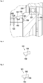
- FIG 2 a sectional view of a slip-ring assembly 200 is shown.
- the slip-ring assembly 200 comprises a stationary part 210 and a rotating part 220 forming a housing for the slip-ring module assembly 100 and holding the slip-ring module assembly 100.
- the slip-ring module assembly 100 comprises at least a slip-ring module body 105 and a plurality of sliding tracks 120.
- the slip-ring module assembly 100 preferably is cylindrical and rotational symmetrical about an axis of rotation 101. There may be minor deviations like the sliding track contact pins 122.
- figure 3 a detail of figure 2 is shown. Here, the section comprising a finger 181 at the second holder 170 is shown enlarged.
- a modified finger 181 is shown.
- the protrusion 192 has an undercut which may interface with a protrusion in groove 182 and which may lock the finger 181 within the module 105.
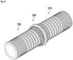
- Figure 8 shows a double slipring module assembly.
- two modules 105, 315 are connected together by a double holder 320.
- the double holder has fingers 181 on two axially opposing sides and around a common rotation axis.
- here may be holders 160, 170 (not shown) at the ends of the modules.
Landscapes
- Snaps, Bayonet Connections, Set Pins, And Snap Rings (AREA)
- Rolling Contact Bearings (AREA)
- Power Steering Mechanism (AREA)
- Mutual Connection Of Rods And Tubes (AREA)
Claims (15)
- Schleifringmodul-Baugruppe (100), umfassend ein Schleifringmodul (105) und einen ersten Halter (160) und/oder einen zweiten Halter (170),wobei das Schleifringmodul (105) eine zylindrische Form um eine Mittelachse (101) aufweist und ein erstes Ende (175a) und ein zweites, dem ersten Ende gegenüberliegendes Ende (175b) hat, und Folgendes umfasst:- einen Schleifringmodulkörper (110), wobei der Körper zumindest ein elektrisch isolierendes Material umfasst,- mindestens eine Schleifbahn (120), wobei die mindestens eine Schleifbahn (120) ein elektrisch leitfähiges Material umfasst,dadurch gekennzeichnet, dassa) das Schleifringmodul (105) an dem ersten Ende (175a) eine erste radiale Nut (182a) aufweist, und der erste Halter (160) an das erste Ende (175a) des Schleifringmoduls (105) passt, und der erste Halter (160) mehrere Fingern (181) umfasst, die in die erste radiale Nut (181) hineinreichen, wenn er an dem Schleifringmodul (105) angebracht ist, wobei die Finger (181) den ersten Halter (160) an dem Modul (105) verriegeln,
und/oderb) das Schleifringmodul (105) eine zweite radiale Nut (182) an dem zweiten Ende (175b) aufweist und der zweite Halter (170) an das zweite Ende (175b) des Schleifringmoduls (105) passt, und der zweite Halter (170) mehrere Fingern (181) umfasst, die in die zweite radiale Nut (182) hineinreichen, wenn er an dem Schleifringmodul (105) angebracht ist, wobei die Finger (181) den zweiten Halter (170) an dem Modul (105) verriegeln. - Schleifringmodul-Baugruppe (100), umfassend ein erstes Schleifringmodul (105), ein zweites Schleifringmodul (315) und einen Doppelhalter (320), wobei das erste Schleifringmodul (105) und das zweite Schleifringmodul (315) jeweils eine zylindrische Form um eine Mittelachse (101) aufweisen, und jeweils ein erstes Ende (175a) und ein dem ersten Ende gegenüberliegendes zweites Ende (175b) aufweisen, und jeweils weiterhin Folgendes umfassen:- einen Schleifringmodulkörper (110), wobei der Körper zumindest ein elektrisch isolierendes Material umfasst,- mindestens eine Schleifbahn (120), wobei die mindestens eine Schleifbahn (120) ein elektrisch leitfähiges Material umfasst,dadurch gekennzeichnet, dassdas erste Schleifringmodul (105) eine erste radiale Nut (182a) an dem ersten Ende aufweist, und das zweite Schleifringmodul (315) eine zweite radiale Nut (182b) an dem zweiten Ende aufweist, undder Doppelhalter (320) zwei axial gegenüberliegende Enden (331, 332) aufweist, welche mehrere Fingern (181) um eine gemeinsame Mittelachse (101) umfassen, undein erstes Ende (331) des Doppelhalters in das erste Ende des ersten Schleifringmoduls (105) passt, wobei die mehreren Finger auf dem ersten Ende des Doppelhalters in die erste radiale Nut (182) hineinreichen, wenn er an dem ersten Schleifringmodul (105) angebracht wird,und ein zweites Ende (332) des Doppelhalters in das zweite Ende des zweiten Schleifringmoduls (315) passt, wobei die mehreren Finger auf dem zweiten Ende des Doppelhalters in die zweite radiale Nut (182) hineinreichen, wenn er an dem zweiten Schleifringmodul (315) angebracht wird, undwobei die Finger den Doppelhalter (320) mit den Modulen (105, 315) verriegeln.
- Schleifringmodul-Baugruppe (100) nach Anspruch 1,
dadurch gekennzeichnet, dassentweder der erste Halter (160) und/oder der zweite Halter (170) ein Doppelhalter (320) ist,die Schleifringmodul-Baugruppe (100) weiterhin ein erstes Schleifringmodul (105) und ein zweites Schleifmodul (315) umfasst,das zweite Schleifringmodul (315) eine zylindrische Form um eine Mittelachse (101) aufweist und ein erstes Ende (175a) und ein zweites, dem ersten Ende gegenüberliegendes Ende (175b) aufweist, und das zweite Schleifringmodul (315) weiterhin Folgendes umfasst:- einen Schleifringmodulkörper (110), wobei der Körper mindestens ein elektrisch isolierendes Material umfasst,- mindestens eine Schleifbahn (120), wobei die mindestens eine Schleifbahn (120) ein elektrisch leitfähiges Material umfasst,dadurch gekennzeichnet, dassdas erste Schleifringmodul (105) eine erste radiale Nut (182a) an dem ersten Ende, und das zweite Schleifringmodul (315) eine zweite radiale Nut (182b) an dem zweiten Ende aufweist, undder Doppelhalter (320) zwei axial gegenüberliegende Enden (331, 332) aufweist, welche mehrere Finger (181) um eine gemeinsame Mittelachse (101) umfassen, und ein erstes (331) Ende des Doppelhalters in das erste Ende des ersten Schleifringmoduls (105) passt, wobei die mehreren Finger auf dem Doppelhalter in die erste radiale Nut (182) hineinreichen, wenn er an dem ersten Schleifringmodul (105) angebracht wird,und ein zweites Ende (332) des Doppelhalters in das zweite Ende des zweiten Schleifringmoduls (315) passt, wobei die mehreren Finger auf dem Doppelhalter in die zweite radiale Nut (182) hineinreichen, wenn er an dem zweiten Schleifringmodul (315) angebracht wird, unddie Finger den Doppelhalter (320) mit den Modulen (105, 315) verriegeln. - Schleifringmodul-Baugruppe (100) nach Anspruch 1 und 2 oder Anspruch 3, umfassend einen Doppelhalter (320) zwischen einem zweiten Ende eines ersten Schleifringmoduls (105) und einem ersten Ende eines zweiten Schleifringmoduls (315), und
einen ersten Halter (160) an einem ersten Ende des ersten Schleifringmoduls (105) und einen zweiten Halter (170) an einem zweiten Ende des ersten Schleifringmoduls (315). - Schleifringmodul-Baugruppe (100) nach beliebigen der vorhergehenden Ansprüche,
dadurch gekennzeichnet, dass
das Schleifringmodul (105) mehrere voneinander isolierte Schleifbahnen (120) umfasst. - Schleifringmodul-Baugruppe (100) nach beliebigen der vorhergehenden Ansprüche,
dadurch gekennzeichnet, dass
mindestens eine Endfläche (130) des Modulkörpers (110) eine Aufnahme zum Aufnehmen gegenläufiger Federn des mindestens einen Halters (160) aufweist. - Schleifringmodul-Baugruppe (100) nach beliebigen der vorhergehenden Ansprüche,
dadurch gekennzeichnet, dass
die mindestens eine Endfläche (130) des Modulkörpers (110) eine Nut für einen Dichtungsring (184) aufweist. - Schleifringmodul-Baugruppe (100) nach beliebigen der vorhergehenden Ansprüche,
dadurch gekennzeichnet, dass
mindestens einer der Halter (160, 170) eine Fläche aufweist, die mit mindestens einer eine Nut für einen Dichtungsring (184) aufweisenden Endfläche (130) des Modulkörpers (110) zusammenpasst. - Schleifringmodul-Baugruppe (100) nach beliebigen der vorhergehenden Ansprüche,
dadurch gekennzeichnet, dass
mindestens ein Dichtungsring (184) zwischen mindestens einer Endfläche (130) des Modulkörpers (110) und mindestens einem der Halter (160, 170) angeordnet ist. - Schleifringmodul-Baugruppe (100) nach beliebigen der vorhergehenden Ansprüche,
dadurch gekennzeichnet, dass
mindestens einer der Halter (160, 170) eine Nut (186) für einen Wellenverriegelungsring (185) aufweist. - Schleifringmodul-Baugruppe (100) nach beliebigen der vorhergehenden Ansprüche,
dadurch gekennzeichnet, dass
mindestens einer der Halter (160, 170) einen Lagersitz für ein Kugellager (211, 221) oder ein Gleitlager aufweist. - Schleifringmodul-Baugruppe (100) nach beliebigen der vorhergehenden Ansprüche,
dadurch gekennzeichnet, dass
mindestens einer der Halter (160, 170, 310) eine Axialfeder (311, 321) zum Aufbringen einer Axialkraft zwischen dem mindestens einen Halter und dem Schleifringmodul aufweist. - Schleifringmodul-Baugruppe (100) nach beliebigen der vorhergehenden Ansprüche,
dadurch gekennzeichnet, dass
mindestens zwei Schleifringmodule (105, 315) durch einen Doppelhalter miteinander verbunden sind, wobei der Doppelhalter mehrere Finger an zwei axial gegenüberliegenden Seiten und um eine gemeinsame Mittelachse umfasst. - Schleifringmodul-Baugruppe (100) nach beliebigen der vorhergehenden Ansprüche,
dadurch gekennzeichnet, dass
die Schleifringmodul-Baugruppe (100) eine freie innere Bohrung bereitstellt. - Schleifring-Baugruppe (200) umfassend eine Schleifringmodul-Baugruppe (100) nach einem der vorhergehenden Ansprüche,
dadurch gekennzeichnet, dass
ein stationärer Teil (210) welcher den ersten Halter (160) durch ein erstes Lagers (211) und ein rotierender Teil (220), der den zweiten Halter (170) durch ein zweites Lager (221) hält, vorgesehen sind.
Applications Claiming Priority (2)
| Application Number | Priority Date | Filing Date | Title |
|---|---|---|---|
| EP19152302.6A EP3683902B1 (de) | 2019-01-17 | 2019-01-17 | Einrastbares schleifringmodul |
| PCT/EP2020/050668 WO2020148221A1 (en) | 2019-01-17 | 2020-01-13 | Snap-in slipring module |
Publications (2)
| Publication Number | Publication Date |
|---|---|
| EP3912232A1 EP3912232A1 (de) | 2021-11-24 |
| EP3912232B1 true EP3912232B1 (de) | 2024-07-03 |
Family
ID=65036676
Family Applications (2)
| Application Number | Title | Priority Date | Filing Date |
|---|---|---|---|
| EP19152302.6A Active EP3683902B1 (de) | 2019-01-17 | 2019-01-17 | Einrastbares schleifringmodul |
| EP20700171.0A Active EP3912232B1 (de) | 2019-01-17 | 2020-01-13 | Einrastbarer schleifringmodul |
Family Applications Before (1)
| Application Number | Title | Priority Date | Filing Date |
|---|---|---|---|
| EP19152302.6A Active EP3683902B1 (de) | 2019-01-17 | 2019-01-17 | Einrastbares schleifringmodul |
Country Status (3)
| Country | Link |
|---|---|
| EP (2) | EP3683902B1 (de) |
| CN (1) | CN112868142B (de) |
| WO (1) | WO2020148221A1 (de) |
Families Citing this family (1)
| Publication number | Priority date | Publication date | Assignee | Title |
|---|---|---|---|---|
| DE102023206469A1 (de) | 2023-07-07 | 2025-01-09 | Vitesco Technologies Germany Gmbh | Schleifringmodul, Rotor für eine fremderregte elektrische Maschine und Verfahren zur Herstellung eines Rotors |
Family Cites Families (9)
| Publication number | Priority date | Publication date | Assignee | Title |
|---|---|---|---|---|
| FR2524212A1 (fr) * | 1982-03-23 | 1983-09-30 | Mecanismes Comp Ind De | Collecteur pour moteur electrique miniature |
| DE3838436C2 (de) * | 1988-11-12 | 2002-09-19 | Bosch Gmbh Robert | Schleifringanordnung |
| GB2339635B (en) * | 1998-06-24 | 2003-01-29 | Jasun Engineering Ltd | Slip ring assembly |
| DE10161740B4 (de) | 2001-12-15 | 2006-01-26 | Stemmann-Technik Gmbh | Schleifringübertrager |
| DE10324708A1 (de) | 2003-05-30 | 2004-12-16 | Ltn Servotechnik Gmbh | Schleifringelement und Verfahren zu dessen Herstellung |
| JP2008092706A (ja) * | 2006-10-03 | 2008-04-17 | Nippon Densan Corp | ブラシレスモータおよびこれを搭載するディスク駆動装置 |
| DK200801474A (en) * | 2008-10-27 | 2009-11-19 | Vestas Wind Sys As | Slip ring assembly with shaft holder |
| DE102012220293A1 (de) | 2012-11-07 | 2014-05-08 | Wobben Properties Gmbh | Schleifringübertrager |
| CN205985694U (zh) * | 2016-07-12 | 2017-02-22 | 杭州欣扬科技有限公司 | 一种分体式过孔导电滑环 |
-
2019
- 2019-01-17 EP EP19152302.6A patent/EP3683902B1/de active Active
-
2020
- 2020-01-13 WO PCT/EP2020/050668 patent/WO2020148221A1/en not_active Ceased
- 2020-01-13 CN CN202080005769.6A patent/CN112868142B/zh active Active
- 2020-01-13 EP EP20700171.0A patent/EP3912232B1/de active Active
Also Published As
| Publication number | Publication date |
|---|---|
| EP3912232A1 (de) | 2021-11-24 |
| CN112868142B (zh) | 2023-11-07 |
| EP3683902B1 (de) | 2022-07-27 |
| WO2020148221A1 (en) | 2020-07-23 |
| CN112868142A (zh) | 2021-05-28 |
| EP3683902A1 (de) | 2020-07-22 |
Similar Documents
| Publication | Publication Date | Title |
|---|---|---|
| EP0180773B1 (de) | Bürstenhalter für drehende elektrische Maschinen | |
| US8616897B2 (en) | Slip-ring unit | |
| EP2063501B1 (de) | Koaxialkabelstecker für geriffeltes Kabel | |
| US9570849B2 (en) | Float plate for blind matable electrical cable connectors | |
| EP3912232B1 (de) | Einrastbarer schleifringmodul | |
| CN110148866B (zh) | 导电滑环 | |
| US4870311A (en) | Wireless slip ring assembly | |
| US20070167032A1 (en) | Slip-ring brush and slip-ring unit equipped with such a slip-ring brush | |
| JPH08236238A (ja) | ロータリー電気コネクタ | |
| CN1071897C (zh) | 复合环构件、特别是一种可装配于滚动轴承的磁性探测构件 | |
| EP4358375B1 (de) | Montagestruktur für den erdungsring eines motors | |
| US20020034887A1 (en) | Device for contacting transmission of electrical signals by means of roll bodies | |
| JP2006084212A (ja) | 両端変位型コンタクトプローブ | |
| US6007344A (en) | Multiple brush steering wheel commutator | |
| CN101361237B (zh) | 旋转连接器 | |
| US20250230838A1 (en) | Roller flange, external rotor motor and conveyor roller | |
| EP4188752B1 (de) | Uhrfeder mit rollkontakten | |
| US7256713B2 (en) | Absolute angle detecting device | |
| EP3641076B1 (de) | Schleifringgehäuse mit bajonettverschluss | |
| JP2011204423A (ja) | 同軸コネクタ用回転機構部品および同軸コネクタ | |
| US20030124891A1 (en) | Electrical connector between two end points | |
| CN100476362C (zh) | 绝对角检测装置 | |
| CN113875099A (zh) | 具有卡口锁的滑环壳体 | |
| CN109642993A (zh) | 光连接器 | |
| EP0809873B1 (de) | Steuerradverbinder mit mehrfachbürste |
Legal Events
| Date | Code | Title | Description |
|---|---|---|---|
| STAA | Information on the status of an ep patent application or granted ep patent |
Free format text: STATUS: UNKNOWN |
|
| STAA | Information on the status of an ep patent application or granted ep patent |
Free format text: STATUS: THE INTERNATIONAL PUBLICATION HAS BEEN MADE |
|
| PUAI | Public reference made under article 153(3) epc to a published international application that has entered the european phase |
Free format text: ORIGINAL CODE: 0009012 |
|
| STAA | Information on the status of an ep patent application or granted ep patent |
Free format text: STATUS: REQUEST FOR EXAMINATION WAS MADE |
|
| 17P | Request for examination filed |
Effective date: 20210519 |
|
| AK | Designated contracting states |
Kind code of ref document: A1 Designated state(s): AL AT BE BG CH CY CZ DE DK EE ES FI FR GB GR HR HU IE IS IT LI LT LU LV MC MK MT NL NO PL PT RO RS SE SI SK SM TR |
|
| DAV | Request for validation of the european patent (deleted) | ||
| DAX | Request for extension of the european patent (deleted) | ||
| STAA | Information on the status of an ep patent application or granted ep patent |
Free format text: STATUS: EXAMINATION IS IN PROGRESS |
|
| 17Q | First examination report despatched |
Effective date: 20231121 |
|
| GRAP | Despatch of communication of intention to grant a patent |
Free format text: ORIGINAL CODE: EPIDOSNIGR1 |
|
| STAA | Information on the status of an ep patent application or granted ep patent |
Free format text: STATUS: GRANT OF PATENT IS INTENDED |
|
| RIC1 | Information provided on ipc code assigned before grant |
Ipc: H01R 39/64 20060101ALN20240223BHEP Ipc: H01R 39/08 20060101ALN20240223BHEP Ipc: H01R 39/14 20060101AFI20240223BHEP |
|
| INTG | Intention to grant announced |
Effective date: 20240315 |
|
| GRAS | Grant fee paid |
Free format text: ORIGINAL CODE: EPIDOSNIGR3 |
|
| GRAA | (expected) grant |
Free format text: ORIGINAL CODE: 0009210 |
|
| STAA | Information on the status of an ep patent application or granted ep patent |
Free format text: STATUS: THE PATENT HAS BEEN GRANTED |
|
| AK | Designated contracting states |
Kind code of ref document: B1 Designated state(s): AL AT BE BG CH CY CZ DE DK EE ES FI FR GB GR HR HU IE IS IT LI LT LU LV MC MK MT NL NO PL PT RO RS SE SI SK SM TR |
|
| RAP3 | Party data changed (applicant data changed or rights of an application transferred) |
Owner name: SCHLEIFRING GMBH |
|
| REG | Reference to a national code |
Ref country code: CH Ref legal event code: EP |
|
| REG | Reference to a national code |
Ref country code: DE Ref legal event code: R096 Ref document number: 602020033263 Country of ref document: DE |
|
| REG | Reference to a national code |
Ref country code: LT Ref legal event code: MG9D |
|
| REG | Reference to a national code |
Ref country code: NL Ref legal event code: MP Effective date: 20240703 |
|
| PG25 | Lapsed in a contracting state [announced via postgrant information from national office to epo] |
Ref country code: PT Free format text: LAPSE BECAUSE OF FAILURE TO SUBMIT A TRANSLATION OF THE DESCRIPTION OR TO PAY THE FEE WITHIN THE PRESCRIBED TIME-LIMIT Effective date: 20241104 |
|
| REG | Reference to a national code |
Ref country code: AT Ref legal event code: MK05 Ref document number: 1700824 Country of ref document: AT Kind code of ref document: T Effective date: 20240703 |
|
| PG25 | Lapsed in a contracting state [announced via postgrant information from national office to epo] |
Ref country code: NL Free format text: LAPSE BECAUSE OF FAILURE TO SUBMIT A TRANSLATION OF THE DESCRIPTION OR TO PAY THE FEE WITHIN THE PRESCRIBED TIME-LIMIT Effective date: 20240703 |
|
| PG25 | Lapsed in a contracting state [announced via postgrant information from national office to epo] |
Ref country code: PT Free format text: LAPSE BECAUSE OF FAILURE TO SUBMIT A TRANSLATION OF THE DESCRIPTION OR TO PAY THE FEE WITHIN THE PRESCRIBED TIME-LIMIT Effective date: 20241104 Ref country code: NL Free format text: LAPSE BECAUSE OF FAILURE TO SUBMIT A TRANSLATION OF THE DESCRIPTION OR TO PAY THE FEE WITHIN THE PRESCRIBED TIME-LIMIT Effective date: 20240703 |
|
| PG25 | Lapsed in a contracting state [announced via postgrant information from national office to epo] |
Ref country code: NO Free format text: LAPSE BECAUSE OF FAILURE TO SUBMIT A TRANSLATION OF THE DESCRIPTION OR TO PAY THE FEE WITHIN THE PRESCRIBED TIME-LIMIT Effective date: 20241003 |
|
| PG25 | Lapsed in a contracting state [announced via postgrant information from national office to epo] |
Ref country code: FI Free format text: LAPSE BECAUSE OF FAILURE TO SUBMIT A TRANSLATION OF THE DESCRIPTION OR TO PAY THE FEE WITHIN THE PRESCRIBED TIME-LIMIT Effective date: 20240703 Ref country code: GR Free format text: LAPSE BECAUSE OF FAILURE TO SUBMIT A TRANSLATION OF THE DESCRIPTION OR TO PAY THE FEE WITHIN THE PRESCRIBED TIME-LIMIT Effective date: 20241004 Ref country code: PL Free format text: LAPSE BECAUSE OF FAILURE TO SUBMIT A TRANSLATION OF THE DESCRIPTION OR TO PAY THE FEE WITHIN THE PRESCRIBED TIME-LIMIT Effective date: 20240703 |
|
| PG25 | Lapsed in a contracting state [announced via postgrant information from national office to epo] |
Ref country code: BG Free format text: LAPSE BECAUSE OF FAILURE TO SUBMIT A TRANSLATION OF THE DESCRIPTION OR TO PAY THE FEE WITHIN THE PRESCRIBED TIME-LIMIT Effective date: 20240703 |
|
| PG25 | Lapsed in a contracting state [announced via postgrant information from national office to epo] |
Ref country code: LV Free format text: LAPSE BECAUSE OF FAILURE TO SUBMIT A TRANSLATION OF THE DESCRIPTION OR TO PAY THE FEE WITHIN THE PRESCRIBED TIME-LIMIT Effective date: 20240703 |
|
| PG25 | Lapsed in a contracting state [announced via postgrant information from national office to epo] |
Ref country code: AT Free format text: LAPSE BECAUSE OF FAILURE TO SUBMIT A TRANSLATION OF THE DESCRIPTION OR TO PAY THE FEE WITHIN THE PRESCRIBED TIME-LIMIT Effective date: 20240703 Ref country code: IS Free format text: LAPSE BECAUSE OF FAILURE TO SUBMIT A TRANSLATION OF THE DESCRIPTION OR TO PAY THE FEE WITHIN THE PRESCRIBED TIME-LIMIT Effective date: 20241103 |
|
| PG25 | Lapsed in a contracting state [announced via postgrant information from national office to epo] |
Ref country code: CZ Free format text: LAPSE BECAUSE OF FAILURE TO SUBMIT A TRANSLATION OF THE DESCRIPTION OR TO PAY THE FEE WITHIN THE PRESCRIBED TIME-LIMIT Effective date: 20240703 Ref country code: HR Free format text: LAPSE BECAUSE OF FAILURE TO SUBMIT A TRANSLATION OF THE DESCRIPTION OR TO PAY THE FEE WITHIN THE PRESCRIBED TIME-LIMIT Effective date: 20240703 |
|
| PG25 | Lapsed in a contracting state [announced via postgrant information from national office to epo] |
Ref country code: RS Free format text: LAPSE BECAUSE OF FAILURE TO SUBMIT A TRANSLATION OF THE DESCRIPTION OR TO PAY THE FEE WITHIN THE PRESCRIBED TIME-LIMIT Effective date: 20241003 Ref country code: ES Free format text: LAPSE BECAUSE OF FAILURE TO SUBMIT A TRANSLATION OF THE DESCRIPTION OR TO PAY THE FEE WITHIN THE PRESCRIBED TIME-LIMIT Effective date: 20240703 |
|
| PG25 | Lapsed in a contracting state [announced via postgrant information from national office to epo] |
Ref country code: RS Free format text: LAPSE BECAUSE OF FAILURE TO SUBMIT A TRANSLATION OF THE DESCRIPTION OR TO PAY THE FEE WITHIN THE PRESCRIBED TIME-LIMIT Effective date: 20241003 Ref country code: PL Free format text: LAPSE BECAUSE OF FAILURE TO SUBMIT A TRANSLATION OF THE DESCRIPTION OR TO PAY THE FEE WITHIN THE PRESCRIBED TIME-LIMIT Effective date: 20240703 Ref country code: NO Free format text: LAPSE BECAUSE OF FAILURE TO SUBMIT A TRANSLATION OF THE DESCRIPTION OR TO PAY THE FEE WITHIN THE PRESCRIBED TIME-LIMIT Effective date: 20241003 Ref country code: LV Free format text: LAPSE BECAUSE OF FAILURE TO SUBMIT A TRANSLATION OF THE DESCRIPTION OR TO PAY THE FEE WITHIN THE PRESCRIBED TIME-LIMIT Effective date: 20240703 Ref country code: IS Free format text: LAPSE BECAUSE OF FAILURE TO SUBMIT A TRANSLATION OF THE DESCRIPTION OR TO PAY THE FEE WITHIN THE PRESCRIBED TIME-LIMIT Effective date: 20241103 Ref country code: HR Free format text: LAPSE BECAUSE OF FAILURE TO SUBMIT A TRANSLATION OF THE DESCRIPTION OR TO PAY THE FEE WITHIN THE PRESCRIBED TIME-LIMIT Effective date: 20240703 Ref country code: GR Free format text: LAPSE BECAUSE OF FAILURE TO SUBMIT A TRANSLATION OF THE DESCRIPTION OR TO PAY THE FEE WITHIN THE PRESCRIBED TIME-LIMIT Effective date: 20241004 Ref country code: FI Free format text: LAPSE BECAUSE OF FAILURE TO SUBMIT A TRANSLATION OF THE DESCRIPTION OR TO PAY THE FEE WITHIN THE PRESCRIBED TIME-LIMIT Effective date: 20240703 Ref country code: ES Free format text: LAPSE BECAUSE OF FAILURE TO SUBMIT A TRANSLATION OF THE DESCRIPTION OR TO PAY THE FEE WITHIN THE PRESCRIBED TIME-LIMIT Effective date: 20240703 Ref country code: CZ Free format text: LAPSE BECAUSE OF FAILURE TO SUBMIT A TRANSLATION OF THE DESCRIPTION OR TO PAY THE FEE WITHIN THE PRESCRIBED TIME-LIMIT Effective date: 20240703 Ref country code: BG Free format text: LAPSE BECAUSE OF FAILURE TO SUBMIT A TRANSLATION OF THE DESCRIPTION OR TO PAY THE FEE WITHIN THE PRESCRIBED TIME-LIMIT Effective date: 20240703 Ref country code: AT Free format text: LAPSE BECAUSE OF FAILURE TO SUBMIT A TRANSLATION OF THE DESCRIPTION OR TO PAY THE FEE WITHIN THE PRESCRIBED TIME-LIMIT Effective date: 20240703 |
|
| REG | Reference to a national code |
Ref country code: DE Ref legal event code: R097 Ref document number: 602020033263 Country of ref document: DE |
|
| PG25 | Lapsed in a contracting state [announced via postgrant information from national office to epo] |
Ref country code: DK Free format text: LAPSE BECAUSE OF FAILURE TO SUBMIT A TRANSLATION OF THE DESCRIPTION OR TO PAY THE FEE WITHIN THE PRESCRIBED TIME-LIMIT Effective date: 20240703 Ref country code: RO Free format text: LAPSE BECAUSE OF FAILURE TO SUBMIT A TRANSLATION OF THE DESCRIPTION OR TO PAY THE FEE WITHIN THE PRESCRIBED TIME-LIMIT Effective date: 20240703 Ref country code: SM Free format text: LAPSE BECAUSE OF FAILURE TO SUBMIT A TRANSLATION OF THE DESCRIPTION OR TO PAY THE FEE WITHIN THE PRESCRIBED TIME-LIMIT Effective date: 20240703 |
|
| PG25 | Lapsed in a contracting state [announced via postgrant information from national office to epo] |
Ref country code: EE Free format text: LAPSE BECAUSE OF FAILURE TO SUBMIT A TRANSLATION OF THE DESCRIPTION OR TO PAY THE FEE WITHIN THE PRESCRIBED TIME-LIMIT Effective date: 20240703 |
|
| PG25 | Lapsed in a contracting state [announced via postgrant information from national office to epo] |
Ref country code: SK Free format text: LAPSE BECAUSE OF FAILURE TO SUBMIT A TRANSLATION OF THE DESCRIPTION OR TO PAY THE FEE WITHIN THE PRESCRIBED TIME-LIMIT Effective date: 20240703 Ref country code: IT Free format text: LAPSE BECAUSE OF FAILURE TO SUBMIT A TRANSLATION OF THE DESCRIPTION OR TO PAY THE FEE WITHIN THE PRESCRIBED TIME-LIMIT Effective date: 20240703 |
|
| PLBE | No opposition filed within time limit |
Free format text: ORIGINAL CODE: 0009261 |
|
| STAA | Information on the status of an ep patent application or granted ep patent |
Free format text: STATUS: NO OPPOSITION FILED WITHIN TIME LIMIT |
|
| 26N | No opposition filed |
Effective date: 20250404 |
|
| REG | Reference to a national code |
Ref country code: CH Ref legal event code: PL |
|
| PG25 | Lapsed in a contracting state [announced via postgrant information from national office to epo] |
Ref country code: SE Free format text: LAPSE BECAUSE OF FAILURE TO SUBMIT A TRANSLATION OF THE DESCRIPTION OR TO PAY THE FEE WITHIN THE PRESCRIBED TIME-LIMIT Effective date: 20240703 |
|
| PG25 | Lapsed in a contracting state [announced via postgrant information from national office to epo] |
Ref country code: LU Free format text: LAPSE BECAUSE OF NON-PAYMENT OF DUE FEES Effective date: 20250113 Ref country code: MC Free format text: LAPSE BECAUSE OF FAILURE TO SUBMIT A TRANSLATION OF THE DESCRIPTION OR TO PAY THE FEE WITHIN THE PRESCRIBED TIME-LIMIT Effective date: 20240703 |
|
| PG25 | Lapsed in a contracting state [announced via postgrant information from national office to epo] |
Ref country code: BE Free format text: LAPSE BECAUSE OF NON-PAYMENT OF DUE FEES Effective date: 20250131 |
|
| PG25 | Lapsed in a contracting state [announced via postgrant information from national office to epo] |
Ref country code: CH Free format text: LAPSE BECAUSE OF NON-PAYMENT OF DUE FEES Effective date: 20250131 |
|
| REG | Reference to a national code |
Ref country code: BE Ref legal event code: MM Effective date: 20250131 |
|
| PG25 | Lapsed in a contracting state [announced via postgrant information from national office to epo] |
Ref country code: IE Free format text: LAPSE BECAUSE OF NON-PAYMENT OF DUE FEES Effective date: 20250113 |
|
| PGFP | Annual fee paid to national office [announced via postgrant information from national office to epo] |
Ref country code: GB Payment date: 20260122 Year of fee payment: 7 |
|
| PGFP | Annual fee paid to national office [announced via postgrant information from national office to epo] |
Ref country code: DE Payment date: 20260120 Year of fee payment: 7 |
|
| PGFP | Annual fee paid to national office [announced via postgrant information from national office to epo] |
Ref country code: FR Payment date: 20260128 Year of fee payment: 7 |