EP3912456B1 - Véhicule agricole avec dispositif de retenue pour déblocage de coupe-vent - Google Patents
Véhicule agricole avec dispositif de retenue pour déblocage de coupe-vent Download PDFInfo
- Publication number
- EP3912456B1 EP3912456B1 EP21174859.5A EP21174859A EP3912456B1 EP 3912456 B1 EP3912456 B1 EP 3912456B1 EP 21174859 A EP21174859 A EP 21174859A EP 3912456 B1 EP3912456 B1 EP 3912456B1
- Authority
- EP
- European Patent Office
- Prior art keywords
- windguard
- tines
- pickup
- actuator
- retainer
- Prior art date
- Legal status (The legal status is an assumption and is not a legal conclusion. Google has not performed a legal analysis and makes no representation as to the accuracy of the status listed.)
- Active
Links
Images


Classifications
-
- A—HUMAN NECESSITIES
- A01—AGRICULTURE; FORESTRY; ANIMAL HUSBANDRY; HUNTING; TRAPPING; FISHING
- A01F—PROCESSING OF HARVESTED PRODUCE; HAY OR STRAW PRESSES; DEVICES FOR STORING AGRICULTURAL OR HORTICULTURAL PRODUCE
- A01F15/00—Baling presses for straw, hay or the like
- A01F15/08—Details
- A01F15/10—Feeding devices for the crop material e.g. precompression devices
- A01F15/106—Feeding devices for the crop material e.g. precompression devices for round balers
-
- A—HUMAN NECESSITIES
- A01—AGRICULTURE; FORESTRY; ANIMAL HUSBANDRY; HUNTING; TRAPPING; FISHING
- A01D—HARVESTING; MOWING
- A01D89/00—Pick-ups for loaders, chaff-cutters, balers, field-threshers, or the like, i.e. attachments for picking-up hay or the like field crops
- A01D89/006—Accessories
- A01D89/008—Devices cooperating with the pick-up
-
- A—HUMAN NECESSITIES
- A01—AGRICULTURE; FORESTRY; ANIMAL HUSBANDRY; HUNTING; TRAPPING; FISHING
- A01F—PROCESSING OF HARVESTED PRODUCE; HAY OR STRAW PRESSES; DEVICES FOR STORING AGRICULTURAL OR HORTICULTURAL PRODUCE
- A01F15/00—Baling presses for straw, hay or the like
- A01F15/07—Rotobalers, i.e. machines for forming cylindrical bales by winding and pressing
-
- A—HUMAN NECESSITIES
- A01—AGRICULTURE; FORESTRY; ANIMAL HUSBANDRY; HUNTING; TRAPPING; FISHING
- A01F—PROCESSING OF HARVESTED PRODUCE; HAY OR STRAW PRESSES; DEVICES FOR STORING AGRICULTURAL OR HORTICULTURAL PRODUCE
- A01F15/00—Baling presses for straw, hay or the like
- A01F15/08—Details
- A01F15/10—Feeding devices for the crop material e.g. precompression devices
- A01F2015/107—Means for withdrawing knives, rotor or walls of the feeding chamber in case of plugging or congestion
Definitions
- the present invention pertains to feeding assemblies for agricultural vehicles, wherein the assemblies include a windguard.
- Agricultural harvesting machines such as balers, are used to consolidate and package crop material so as to facilitate the storage and handling of the crop material for later use.
- a mower-conditioner is typically used to cut and condition the crop material for windrow drying in the sun.
- an agricultural combine discharges non-grain crop material from the rear of the combine defining the straw (such as wheat or oat straw) which is to be picked up by the baler.
- the cut crop material is typically raked and dried, and a baler, such as a large square baler or round baler, straddles the windrows and travels along the windrows to pick up the crop material and form it into bales.
- a round baler may generally include a chassis, supported by wheels, a pickup unit to engage and lift the crop material into the baler, a cutting unit, a main bale chamber for forming a bale, and a wrapping mechanism for wrapping or tying a material around the bale after it has been formed in the main bale chamber.
- the pickup unit lifts the crop material into the baler. Then, the crop material may be cut into smaller pieces by the cutting unit.
- Many balers include a windguard, which holds down crop material as it is being fed to prevent it from being blown off the pickup floor and ensure adequate compaction of the crop material for appropriate feeding into the vehicle.
- multiple carrier elements e.g.
- rollers, chains and slats, and/or belts will begin to roll a bale of hay within the chamber.
- These carrier elements are movable so that the chamber can initially contract and subsequently expand to maintain an appropriate amount of pressure on the periphery of the bale.
- the rear of the baler is configured to open for allowing the bale to be discharged onto the field.
- US2014/250855 A1 discloses a pick-up assembly having a pick-up drum, rotatably mounted to a frame, a windguard, attached to a support linkage which is pivotably mounted to the frame, at least one winch drum, rotatably attached with respect to the frame and at least one flexible elongate element having opposite first and second end regions. The first end region is attached to the support linkage and the second end region is windably attached to the at least one winch drum.
- the present invention provides a feeding assembly as defined by appended claim 1.
- Preferred aspects of the invention are defined by the dependent claims.
- windguard retainer can retain the windguard in the second position to make it easier to remove a crop material blockage in an area around the pickup.
- An advantage of the present invention is that the windguard tines may be moved while the windguard is retained in the second position, without moving the entirety of the windguard, in order to remove a crop material blockage.
- forward when used in connection with the agricultural baler and/or components thereof are usually determined with reference to the direction of forward operative travel of the towing vehicle, but they should not be construed as limiting.
- longitudinal and “transverse” are determined with reference to the fore-and-aft direction of the towing vehicle and are equally not to be construed as limiting.
- an exemplary embodiment of an agricultural vehicle 10 in the form of a round baler is shown to include a chassis terminating forwardly in a tongue 11 and rearward slightly beyond a transverse axle 12a to which a pair of wheels 12b (only one shown) is mounted, thus forming a wheel supported chassis.
- the chassis supports a series of belts 16 and floor rolls, which together with a first sidewall 14a (shown in the breakout) behind and generally parallel to cover panel 15 and a second sidewall 14b, collectively forming a bale chamber 20.
- Cut crop material is picked up by a pickup 30 and fed through a harvesting assembly into the bale chamber 20 where it is formed into a cylindrically shaped bale by a series of conveyor belts 16.
- the pickup 30 is carried by the chassis and includes a transverse pickup reel 31 and a plurality of tines 32 carried by the pickup reel 31.
- the bale is then optionally wrapped with twine or a net wrapping material dispensed from a wrapping mechanism generally behind shield 40.
- the tailgate 50 pivots upwardly about pivot points 51a, 51b and the bale is discharged onto the ground.
- the agricultural vehicle 10 is illustrated and described as a round baler, in some embodiments the agricultural vehicle 10 is configured as a different type of baler, such as a large square baler, or a different type of vehicle altogether, such as a forage harvester.
- the agricultural vehicle 10 includes a feeding assembly 100 including the previously described pickup 30, a rotor 110 having rotor fins 111 disposed rearwardly from the pickup 30, and a windguard assembly 200.
- the windguard assembly 200 includes a pair of movable support arms 201 (with only one illustrated in FIG. 2 ), which may be pivotably coupled to the chassis of the vehicle 10, and a windguard 202 coupled to the support arms 201.
- the windguard 202 includes a tube 203 and a plurality of windguard tines 204 that are coupled to the tube 203.
- the windguard 202 may be moved, such as pivoted, by the support arms 201 between various positions, as is known.
- the windguard 202 may be moved, e.g., pivoted, from a first position to a second position that is elevated relative to the first position.
- the second position is a fully raised position of the windguard 202.
- the windguard 202 is pivoted by the support arms 201 about a first axis of rotation AR1, but it should be appreciated that the windguard 202 may be moved between the first position and the second position in a variety of ways.
- the windguard 202 can be moved to various positions to hold down and compact crop material as it is collected by the pickup 30.
- the feeding assembly 100 includes a windguard retainer 220 that is configured to engage the windguard 202 when the windguard 202 is elevated to the second position and retain the windguard 202 in the second position.
- the windguard retainer 220 is coupled to a frame 230 of the vehicle 10 and may include a base portion 221 with at least one hook 222, illustrated as two hooks, that is placed, or may be placed, in the movement path of the windguard 202 to the second position.
- the windguard 202 may engage the hooks 222, which retain the windguard 202 in place.
- the tube 203 of the windguard 202 may be engaged by the hooks 222 so the hooks 222 retain the windguard 202 in the second position via the tube 203.
- the windguard retainer 220 is illustrated and described as including hooks 222 to engage and retain the windguard 202 in the second position, the windguard retainer 220 may be configured in other ways to engage and retain the windguard 202 in the second position, e.g., by including a slot that captures a portion of the windguard 202.
- windguard retainer 220 is illustrated as engaging the tube 203 of the windguard 202 to retain the windguard 202 in the second position, in some embodiments a windguard retainer 220A (illustrated in dashed lines) is provided, alternatively or additionally to the windguard retainer 220, that is configured to engage at least one of the support arms 201 when the windguard 202 is in the second position to retain the windguard 202 in the second position. It should thus be appreciated that the windguard 202 may be retained by one or more windguard retainers 220, 220A in a variety of ways according to the present disclosure.
- the support arms 201 are pivotable about the first axis of rotation AR1 to pivot the entirety of the windguard 202 between the first position and the second position, as previously described.
- the windguard tines 204 may be configured to move, such as pivot, without moving the entirety of the windguard 202 while the windguard 202 is in the second position to, for example, dislodge and remove a crop material blockage that has developed in an area around the pickup 30.
- the windguard tines 204 may be configured to be pivoted toward and/or away from the pickup 30, e.g., downwardly and/or upwardly, to dislodge the crop material blockage.
- the windguard tines 204 may be pivotable about a second axis of rotation AR2, illustrated as being defined by the tube 203, that is non-coaxial with the first axis of rotation AR1.
- FIG. 3 illustrates the windguard tines 204 in an unpivoted position (illustrated in solid lines) and a pivoted position (illustrated in dashed lines), with the windguard tines 204 being pivoted to the pivoted position to act as a rake and remove crop material from the area around the pickup 30.
- Retaining the windguard 202 in the second position with the windguard retainer 220 provides support for the windguard 202, which allows the windguard tines 204 to be moved, such as pivoted toward the pickup 30, independently of movement of the support arms 201 and be used to clear a blockage from the area around the pickup 30.
- the windguard tines 204 are be moved, for example, by the tube 203 being pivotable with respect to the support arms 201 so the tube 203 and the coupled windguard tines 204 are pivotable independently of the support arms 201.
- the tube 203 may be pivotable independently of the support arms 201 by, for example, mounting the tube 203 on a bushing 205 carried by each support arm 201 or by journaling each end of the tube 203 in a slot formed in the support arms 201.
- the windguard tines 204 may be pivotable with respect to the tube 203 without the tube 203 being pivotable with respect to the support arms 201 by, for example, forming the windguard tines 204 of a flexible material that can elastically bend when force is applied thereto or by pivotably mounting each of the windguard tines 204 to the tube 203. It should thus be appreciated that the windguard tines 204 may be moved without moving the entirety of the windguard 202 in a large variety of ways according to the present disclosure.
- the feeding assembly 100 includes an actuator 310 that is configured to selectively activate and move at least one of the windguard tines 204 toward, and/or away from, the pickup 30 to clear a crop material blockage.
- the actuator 310 may, as illustrated, include a movable actuator rod 311 and a bar 312 coupled to the actuator rod 311.
- the bar 312 is configured to bear on at least two of the windguard tines 204 to pivot the at least two windguard tines 204 downwardly.
- the actuator rod 311 may be extended to force the bar 312 against the windguard tines 204 and cause the windguard tines 204 to pivot about the second axis of rotation AR2.
- an actuator may be provided to move, e.g., pivot, the windguard tines 204 toward and/or away from the pickup 30 in other ways, e.g., by coupling an actuator directly to one or more of the windguard tines 204 and activating the actuator to pivot the windguard tines 204.
- the actuator rod 311 can then be retracted to return the windguard tines 204 to the unpivoted position.
- the tube 203 and/or at least one of the windguard tines 204 is coupled to a spring 206 that is configured to return the tube 203 and/or the windguard tines 204 to the unpivoted position when the pivoting force acting on the tube 203 and/or the windguard tine(s) 204 is removed.
- a stop 207 may also be included to ensure the tube 203 and/or the windguard tines 204 do not excessively pivot when returning to the unpivoted position.
- a controller 320 is operatively coupled to the actuator 310 and configured to output signals to the actuator 310 to control function of the actuator 310.
- the controller 320 may be a baler controller of the baler 10.
- the controller 320 is carried by a vehicle towing the baler 10, such as a tractor, and/or part of an ISOBUS system that controls various functions of the towing vehicle and/or the baler 10.
- the controller 320 is configured to execute a blockage clear protocol, which may begin with the controller 320 outputting a windguard raise signal that causes raising of the windguard 202 to the second position.
- the controller 320 may be configured to determine a clearance C between the pickup reel 31 and the windguard 202 in the second position is at least a defined amount. When the controller 320 determines that the clearance C is at least the defined amount, the controller 320 may responsively output an actuation signal to the actuator 310 to activate the actuator 310, e.g., to extend the actuator rod 311, to move at least one of the windguard tines 204 toward and/or away from the pickup 30 to clear a blockage. The controller 320 may determine the clearance C based on signals from one or more position sensors 321, 322 associated with the windguard 202 and/or the pickup reel 31, which may also be movable, and a difference between the positions of the windguard 202 and the pickup reel 31.
- the controller 320 may be configured to lockout activation of the actuator 310 until the clearance C is at least the defined amount when the windguard 202 is in the second position. By locking out the actuator 310 when the clearance C is not at least the defined amount, the controller 320 can prevent the pivoted windguard tines 204 from contacting the pickup reel 31 and/or tines 32 while clearing the blockage. In some embodiments, the controller 320 is also configured to output a pickup lower signal to cause lowering of the pickup reel 31 when the clearance C is less than the defined amount and the windguard 202 is in the second position.
- the pickup lower signal may cause an actuator coupled to the pickup reel 31 to lower the pickup reel 31 further and, if necessary, may also cause the vehicle 10 to adjust so the ground clearance of the vehicle 10 increases to allow further downward movement of the pickup reel 31.
- the controller 320 may output signals to cause retraction of the actuator rod 311 and lowering of the windguard 202 from the second position to an operating position, e.g., the first position, for further crop material collection. It should thus be appreciated that the controller 320 may automate some or all of the functions needed to clear out a blockage from the area around the pickup 30 using the windguard tines 204 and then return the windguard 202 to an operating position.
- the windguard retainer 220 is movable to engage the windguard 202 and/or disengage from the windguard 202.
- the windguard retainer 220 may be configured similarly to a latch gate where the windguard retainer 220 latches into engagement with the windguard 202 when the windguard 202 is moved to the second position.
- a retainer actuator 240 coupled to the windguard retainer 220 may be selectively activated, by the controller 320 or otherwise, to selectively move the windguard retainer 220 into engagement and/or out of engagement with the windguard 202.
- the retainer actuator 240 may, for example, be coupled to the hooks 222 and configured to move the hooks 222 toward the tube 203 to engage the tube 203 and/or away from the tube 203 to disengage from the windguard 202.
- the retainer actuator 240 moves the windguard retainer 220 in a first direction to engage the windguard 202 in the second position to retain the windguard 202 in the second position and then moves the windguard retainer 220 in a second direction, opposite the first direction, to disengage from the windguard 202 and allow return of the windguard 202 to the first position.
- the controller 320 may control activation of the windguard retainer 220 so the windguard retainer 220 engages the windguard 202 when the windguard 202 reaches the second position and/or disengages from the windguard 202 after pivoting of the windguard tines 204 to clear a blockage.
- the feeding assembly 100 provided according to the present disclosure includes a windguard retainer 220, 220A that can retain the windguard 202 in an elevated second position.
- the windguard 202 being in the elevated second position can maintain an increased clearance between the windguard 202 and the pickup reel 31, which may help with removing crop material blockages around the pickup 30.
- the windguard tines 204 can be moved, without moving the entirety of the windguard 202, toward and/or away from the pickup 30 to remove a crop material blockage, providing additional functionality to the windguard tines 204 and allowing an operator to clear crop material blockages without having to manually remove the crop material blockage.
- the feeding assembly 100 provided according to the present disclosure can reduce the risk of an operator getting injured while clearing crop material blockages around the pickup 30 and also provides a convenient way for an operator to clear crop material blockages without having to leave an operator cabin of a vehicle.
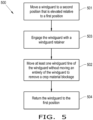
- the method 500 includes moving 501 the windguard 202 to the second position, which is elevated relative to the first position, and moving 502 at least one windguard tine 204 of the windguard 202 without moving the entirety of the windguard 202 to remove a crop material blockage from an area around the pickup 30, as previously described.
- the windguard tine(s) 204 may be moved, for example, by pivoting the windguard tine(s) 204 toward and/or away from the pickup 30.
- the windguard 202 is engaged 503 with the windguard retainer 220, 220A when the windguard 202 is in the second position, prior to moving 502 the windguard tine(s) 204, to support the windguard 202 while moving 502 the windguard tine(s) 204.
- the windguard 202 may be returned 504 to the first position, which may be a collection position, so operation of the vehicle 10 may resume as normal.
Landscapes
- Life Sciences & Earth Sciences (AREA)
- Environmental Sciences (AREA)
- Harvester Elements (AREA)
- Fertilizing (AREA)
Claims (7)
- Un ensemble alimentation (100) pour un véhicule agricole (10), comprenant :un ramasseur (30) comprenant un rabatteur de ramassage (31) portant une pluralité de dents (32) ;un rotor (110) comprenant une pluralité d'ailettes de rotor (111) disposées vers l'arrière du ramasseur (30) ; etun ensemble pare-vent (200) comprenant une paire de bras de soutien mobiles (201) et un pare-vent (202) couplé aux bras de soutien (201), le pare-vent (202) comprenant un tube (203) et une pluralité de dents de pare-vent (204) couplées au tube (203), le pare-vent (202) étant mobile entre une première position à une seconde position qui est surélevée par rapport à la première position ;un dispositif de retenue de pare-vent (220, 220A) configuré pour engager le pare-vent (202) lorsque le pare-vent (202) se trouve dans la seconde position et pour maintenir le pare-vent (202) dans la seconde position, dans lequel les dents du pare-vent (204) sont configurées pour se déplacer sans déplacer la totalité du pare-vent (202) lorsque le pare-vent (202) se trouve dans la seconde position, et dans lequel les bras de soutien (201) peuvent pivoter autour d'un premier axe de rotation (AR1) et les dents du pare-vent (204) peuvent pivoter autour d'un second axe de rotation (AR2) qui n'est pas coaxial avec le premier axe de rotation (AR1), les dents du pare-vent (204) étant configurées pour pivoter en direction et/ou à l'opposé du ramasseur (30) afin de déloger un blocage de matériau récolté ;caractérisé en ce que :
un actionneur (310) configuré pour activer et pivoter de manière sélective au moins une des dents du pare-vent (204) sans déplacer l'intégralité du pare-vent (202). - L'ensemble alimentation (100) selon la revendication 1, comprenant en outre un contrôleur (320) couplé fonctionnellement à l'actionneur (310) et configuré pour :déterminer qu'un dégagement (C) entre le rabatteur de ramassage (31) et le pare-vent (202) dans la seconde position est au moins égal à une valeur définie ; ettransmettre un signal d'actionnement à l'actionneur (310) pour activer l'actionneur (310) afin de faire pivoter l'au moins une dent du pare-vent (204) suite à la détermination que le dégagement (C) est au moins égal à la valeur définie.
- L'ensemble alimentation (100) selon la revendication 2, dans lequel le contrôleur (320) est configuré pour verrouiller l'activation de l'actionneur (310) jusqu'à ce que le dégagement (C) soit au moins égal à la valeur définie pendant que le pare-vent (202) est dans la seconde position.
- L'ensemble alimentation (100) selon l'une quelconque des revendications 1 à 3, dans lequel l'actionneur (310) comprend une tige d'actionneur mobile (311) et une barre (312) couplée à la tige d'actionneur (311) et configurée pour appuyer sur au moins deux des dents du pare-vent (204) afin de déplacer les au moins deux dents du pare-vent (204).
- L'ensemble alimentation (100) selon l'une quelconque des revendications précédentes, dans lequel le dispositif de retenue de pare-vent (220) est configuré pour engager le tube (203) afin de maintenir le pare-vent (202) dans la seconde position.
- L'ensemble alimentation (100) selon l'une quelconque des revendications précédentes, dans lequel le dispositif de retenue de pare-vent (220, 220A) est mobile pour engager le pare-vent (202) et/ou se dégager du pare-vent (202).
- Un véhicule agricole (10) comprenant un châssis soutenant l'ensemble alimentation (100) selon l'une quelconque des revendications précédentes.
Applications Claiming Priority (1)
| Application Number | Priority Date | Filing Date | Title |
|---|---|---|---|
| US202063027122P | 2020-05-19 | 2020-05-19 |
Publications (2)
| Publication Number | Publication Date |
|---|---|
| EP3912456A1 EP3912456A1 (fr) | 2021-11-24 |
| EP3912456B1 true EP3912456B1 (fr) | 2024-12-25 |
Family
ID=76034460
Family Applications (1)
| Application Number | Title | Priority Date | Filing Date |
|---|---|---|---|
| EP21174859.5A Active EP3912456B1 (fr) | 2020-05-19 | 2021-05-19 | Véhicule agricole avec dispositif de retenue pour déblocage de coupe-vent |
Country Status (2)
| Country | Link |
|---|---|
| US (1) | US12089536B2 (fr) |
| EP (1) | EP3912456B1 (fr) |
Families Citing this family (8)
| Publication number | Priority date | Publication date | Assignee | Title |
|---|---|---|---|---|
| US12035659B2 (en) * | 2021-06-23 | 2024-07-16 | Cnh Industrial America Llc | Agricultural implement system with a controller for detecting and mitigating plug conditions |
| US12396402B2 (en) * | 2022-01-31 | 2025-08-26 | Cnh Industrial America Llc | Repositionable windguard assembly for agricultural baler feeder system |
| US12396404B2 (en) * | 2022-01-31 | 2025-08-26 | Cnh Industrial America Llc | Repositionable windguard assembly for agricultural baler feeder system |
| EP4285705B1 (fr) * | 2022-05-30 | 2025-04-16 | CNH Industrial Belgium N.V. | Protection anti-poussière pour un pickup à herbe |
| EP4285711B1 (fr) * | 2022-05-30 | 2025-05-14 | CNH Industrial Belgium N.V. | Élévateur pare-vent pour tête de ramassage d'herbe |
| EP4285710A1 (fr) * | 2022-05-30 | 2023-12-06 | CNH Industrial Belgium N.V. | Lumières de travail pour un collecteur de ramassage de gazon |
| EP4285709B1 (fr) * | 2022-05-30 | 2025-04-23 | CNH Industrial Belgium N.V. | Verrou de protection anti-poussière pour un pickup à herbe |
| US20250151656A1 (en) * | 2023-11-10 | 2025-05-15 | Cnh Industrial America Llc | Windguard assembly for agricultural baler |
Family Cites Families (29)
| Publication number | Priority date | Publication date | Assignee | Title |
|---|---|---|---|---|
| US5131214A (en) * | 1991-01-15 | 1992-07-21 | Vermeer Manufacturing Company | Baler fill monitor |
| FR2776469B1 (fr) * | 1998-03-27 | 2000-05-05 | Idass Sa | Dispositif de relevage d'une vis sans fin de ramasseur d'andains |
| US6134868A (en) | 1999-01-07 | 2000-10-24 | Inforcer, Inc. | Baler plug removing system |
| GB9903624D0 (en) * | 1999-02-18 | 1999-04-07 | Ford New Holland Nv | Movable windguard |
| DE10120124C2 (de) * | 2001-04-25 | 2003-04-30 | Krone Bernhard Gmbh Maschf | Landwirtschaftliche Erntemaschine |
| US6810650B2 (en) * | 2002-03-28 | 2004-11-02 | New Holland North America, Inc. | Replaceable windguard tines for a round baler |
| US6679042B1 (en) * | 2002-11-12 | 2004-01-20 | Acco Corporation | Infeed cutter baler having increased throughput |
| US20060277889A1 (en) * | 2005-06-10 | 2006-12-14 | Sheedy Ronald L | Wind screen hold down attachment |
| DE102005030702A1 (de) * | 2005-06-29 | 2007-01-04 | Deere & Company, Moline | Erntegutaufnahmeeinrichtung und Erntemaschine |
| FR2898243B1 (fr) * | 2006-03-10 | 2008-05-09 | Idass Sa | Engin agricole ramasseur d'andains |
| DE102006059265A1 (de) * | 2006-12-15 | 2008-07-10 | Deere & Company, Moline | Landwirtschaftliche Presse |
| US7448196B2 (en) * | 2007-01-05 | 2008-11-11 | Agco Corporation | Baler with multi-auger pickup |
| DE102007058313B4 (de) | 2007-12-04 | 2016-03-10 | Deere & Company | Anordnung zur Verstellung der Position einer Aufnehmertrommel und eines Niederhalters einer landwirtschaftlichen Erntemaschine |
| DE102008041331A1 (de) * | 2008-08-19 | 2010-02-25 | Deere & Company, Moline | Niederhaltereinrichtung |
| NL1038109C2 (en) * | 2010-06-22 | 2012-01-23 | Forage Innovations Bv | Tine control for balers. |
| BE1019902A3 (nl) * | 2011-04-08 | 2013-02-05 | Cnh Belgium Nv | Opraapeenheid voor een landbouwmachine. |
| BE1020227A3 (nl) * | 2011-10-10 | 2013-06-04 | Cnh Belgium Nv | Opraapeenheid met beweegbaar windscherm. |
| DE102012011591C5 (de) * | 2012-06-13 | 2018-02-15 | Claas Saulgau Gmbh | Aufnahmevorrichtung für eine landwirtschaftliche Erntemaschine |
| BE1020850A3 (nl) * | 2012-07-27 | 2014-06-03 | Cnh Belgium Nv | Windschermmechanisme van een opraper voor een landbouwmachine. |
| US9253948B2 (en) * | 2012-11-27 | 2016-02-09 | Agco Corporation | Continuous round baler with adjustable screed |
| FR2999868B1 (fr) * | 2012-12-20 | 2014-12-12 | Kuhn Sa | Machine agricole de recolte comportant un dispositif de guidage perfectionne des vegetaux |
| EP2777379B1 (fr) | 2013-03-15 | 2016-12-21 | CNH Industrial Belgium nv | Pare-vent à action de came |
| US20140261023A1 (en) * | 2013-03-15 | 2014-09-18 | Cnh Industrial America Llc | Bale forming control system and method |
| US9521807B2 (en) * | 2014-05-05 | 2016-12-20 | Roc S.R.L. | Guiding unit for a device for harvesting the long agricultural products and device for harvesting agricultural products comprising the guiding unit |
| US10111387B1 (en) * | 2017-04-28 | 2018-10-30 | Deere & Company | Baffle float system for baler |
| DE202018107313U1 (de) * | 2018-12-20 | 2020-03-23 | Pöttinger Landtechnik Gmbh | Landwirtschaftliche Erntemaschine |
| US11547053B2 (en) * | 2020-03-04 | 2023-01-10 | Cnh Industrial America Llc | Agricultural vehicle with windguard having offset arms |
| EP4066623A1 (fr) * | 2021-03-31 | 2022-10-05 | CNH Industrial Belgium N.V. | Véhicule agricole avec plaque de guidage flottante |
| US12035659B2 (en) * | 2021-06-23 | 2024-07-16 | Cnh Industrial America Llc | Agricultural implement system with a controller for detecting and mitigating plug conditions |
-
2021
- 2021-05-19 EP EP21174859.5A patent/EP3912456B1/fr active Active
- 2021-05-19 US US17/324,469 patent/US12089536B2/en active Active
Also Published As
| Publication number | Publication date |
|---|---|
| EP3912456A1 (fr) | 2021-11-24 |
| US20210360859A1 (en) | 2021-11-25 |
| US12089536B2 (en) | 2024-09-17 |
Similar Documents
| Publication | Publication Date | Title |
|---|---|---|
| EP3912456B1 (fr) | Véhicule agricole avec dispositif de retenue pour déblocage de coupe-vent | |
| EP0807379B1 (fr) | Presse à balles rondes | |
| US8056314B1 (en) | Wide crop pick-up having primary and secondary stripper plates for converging augers respectively mounted to movable crop guide plate portion and to fixed walls behind the augers | |
| US11547053B2 (en) | Agricultural vehicle with windguard having offset arms | |
| EP1621068B1 (fr) | Ramasseur pour une machine agricole | |
| EP3864952B1 (fr) | Ramasseuse-presse agricole dotée d'un système d'atténuation de surcharge de couteau | |
| EP4223103A1 (fr) | Pare-vent à géométrie variable | |
| EP3871489A1 (fr) | Véhicule agricole à capture réglable | |
| EP3847885B1 (fr) | Ramasseuse-presse agricole dotée de bras de mise sous tension indépendants | |
| US4858419A (en) | Swath treating attachment for a swather | |
| EP4218397A1 (fr) | Pare-vent à géométrie variable | |
| EP4205533B1 (fr) | Ramasseuse-presse agricole avec rampe de libération de balle de préhension | |
| US11917948B2 (en) | Agricultural baler with wrapping material knife to reduce rotor wrap-around | |
| US11672207B2 (en) | Agricultural vehicle with guided rotor knives | |
| US20250151655A1 (en) | Windguard assembly for agricultural baler | |
| US20250151656A1 (en) | Windguard assembly for agricultural baler | |
| US20240138309A1 (en) | Support Wheels for a Pickup Header | |
| US20240423138A1 (en) | Consistent flow windguard for agricultural baler | |
| US12058962B2 (en) | Belt tension lockout device for an agricultural baler | |
| BR102023022417A2 (pt) | Rodas de apoio para um coletor do captador |
Legal Events
| Date | Code | Title | Description |
|---|---|---|---|
| PUAI | Public reference made under article 153(3) epc to a published international application that has entered the european phase |
Free format text: ORIGINAL CODE: 0009012 |
|
| STAA | Information on the status of an ep patent application or granted ep patent |
Free format text: STATUS: THE APPLICATION HAS BEEN PUBLISHED |
|
| AK | Designated contracting states |
Kind code of ref document: A1 Designated state(s): AL AT BE BG CH CY CZ DE DK EE ES FI FR GB GR HR HU IE IS IT LI LT LU LV MC MK MT NL NO PL PT RO RS SE SI SK SM TR |
|
| B565 | Issuance of search results under rule 164(2) epc |
Effective date: 20211019 |
|
| STAA | Information on the status of an ep patent application or granted ep patent |
Free format text: STATUS: REQUEST FOR EXAMINATION WAS MADE |
|
| 17P | Request for examination filed |
Effective date: 20220524 |
|
| RBV | Designated contracting states (corrected) |
Designated state(s): AL AT BE BG CH CY CZ DE DK EE ES FI FR GB GR HR HU IE IS IT LI LT LU LV MC MK MT NL NO PL PT RO RS SE SI SK SM TR |
|
| GRAP | Despatch of communication of intention to grant a patent |
Free format text: ORIGINAL CODE: EPIDOSNIGR1 |
|
| STAA | Information on the status of an ep patent application or granted ep patent |
Free format text: STATUS: GRANT OF PATENT IS INTENDED |
|
| INTG | Intention to grant announced |
Effective date: 20240715 |
|
| RIC1 | Information provided on ipc code assigned before grant |
Ipc: A01D 89/00 20060101AFI20240705BHEP |
|
| GRAS | Grant fee paid |
Free format text: ORIGINAL CODE: EPIDOSNIGR3 |
|
| GRAA | (expected) grant |
Free format text: ORIGINAL CODE: 0009210 |
|
| STAA | Information on the status of an ep patent application or granted ep patent |
Free format text: STATUS: THE PATENT HAS BEEN GRANTED |
|
| AK | Designated contracting states |
Kind code of ref document: B1 Designated state(s): AL AT BE BG CH CY CZ DE DK EE ES FI FR GB GR HR HU IE IS IT LI LT LU LV MC MK MT NL NO PL PT RO RS SE SI SK SM TR |
|
| REG | Reference to a national code |
Ref country code: GB Ref legal event code: FG4D |
|
| REG | Reference to a national code |
Ref country code: CH Ref legal event code: EP |
|
| REG | Reference to a national code |
Ref country code: DE Ref legal event code: R096 Ref document number: 602021023782 Country of ref document: DE |
|
| REG | Reference to a national code |
Ref country code: IE Ref legal event code: FG4D |
|
| REG | Reference to a national code |
Ref country code: LT Ref legal event code: MG9D |
|
| PG25 | Lapsed in a contracting state [announced via postgrant information from national office to epo] |
Ref country code: HR Free format text: LAPSE BECAUSE OF FAILURE TO SUBMIT A TRANSLATION OF THE DESCRIPTION OR TO PAY THE FEE WITHIN THE PRESCRIBED TIME-LIMIT Effective date: 20241225 |
|
| PG25 | Lapsed in a contracting state [announced via postgrant information from national office to epo] |
Ref country code: FI Free format text: LAPSE BECAUSE OF FAILURE TO SUBMIT A TRANSLATION OF THE DESCRIPTION OR TO PAY THE FEE WITHIN THE PRESCRIBED TIME-LIMIT Effective date: 20241225 |
|
| PG25 | Lapsed in a contracting state [announced via postgrant information from national office to epo] |
Ref country code: BG Free format text: LAPSE BECAUSE OF FAILURE TO SUBMIT A TRANSLATION OF THE DESCRIPTION OR TO PAY THE FEE WITHIN THE PRESCRIBED TIME-LIMIT Effective date: 20241225 |
|
| PG25 | Lapsed in a contracting state [announced via postgrant information from national office to epo] |
Ref country code: NO Free format text: LAPSE BECAUSE OF FAILURE TO SUBMIT A TRANSLATION OF THE DESCRIPTION OR TO PAY THE FEE WITHIN THE PRESCRIBED TIME-LIMIT Effective date: 20250325 |
|
| PG25 | Lapsed in a contracting state [announced via postgrant information from national office to epo] |
Ref country code: LV Free format text: LAPSE BECAUSE OF FAILURE TO SUBMIT A TRANSLATION OF THE DESCRIPTION OR TO PAY THE FEE WITHIN THE PRESCRIBED TIME-LIMIT Effective date: 20241225 Ref country code: GR Free format text: LAPSE BECAUSE OF FAILURE TO SUBMIT A TRANSLATION OF THE DESCRIPTION OR TO PAY THE FEE WITHIN THE PRESCRIBED TIME-LIMIT Effective date: 20250326 |
|
| PG25 | Lapsed in a contracting state [announced via postgrant information from national office to epo] |
Ref country code: RS Free format text: LAPSE BECAUSE OF FAILURE TO SUBMIT A TRANSLATION OF THE DESCRIPTION OR TO PAY THE FEE WITHIN THE PRESCRIBED TIME-LIMIT Effective date: 20250325 |
|
| REG | Reference to a national code |
Ref country code: NL Ref legal event code: MP Effective date: 20241225 |
|
| PG25 | Lapsed in a contracting state [announced via postgrant information from national office to epo] |
Ref country code: NL Free format text: LAPSE BECAUSE OF FAILURE TO SUBMIT A TRANSLATION OF THE DESCRIPTION OR TO PAY THE FEE WITHIN THE PRESCRIBED TIME-LIMIT Effective date: 20241225 |
|
| REG | Reference to a national code |
Ref country code: AT Ref legal event code: MK05 Ref document number: 1753355 Country of ref document: AT Kind code of ref document: T Effective date: 20241225 |
|
| PG25 | Lapsed in a contracting state [announced via postgrant information from national office to epo] |
Ref country code: SM Free format text: LAPSE BECAUSE OF FAILURE TO SUBMIT A TRANSLATION OF THE DESCRIPTION OR TO PAY THE FEE WITHIN THE PRESCRIBED TIME-LIMIT Effective date: 20241225 |
|
| PG25 | Lapsed in a contracting state [announced via postgrant information from national office to epo] |
Ref country code: PL Free format text: LAPSE BECAUSE OF FAILURE TO SUBMIT A TRANSLATION OF THE DESCRIPTION OR TO PAY THE FEE WITHIN THE PRESCRIBED TIME-LIMIT Effective date: 20241225 |
|
| PGFP | Annual fee paid to national office [announced via postgrant information from national office to epo] |
Ref country code: DE Payment date: 20250528 Year of fee payment: 5 |
|
| PG25 | Lapsed in a contracting state [announced via postgrant information from national office to epo] |
Ref country code: ES Free format text: LAPSE BECAUSE OF FAILURE TO SUBMIT A TRANSLATION OF THE DESCRIPTION OR TO PAY THE FEE WITHIN THE PRESCRIBED TIME-LIMIT Effective date: 20241225 |
|
| PGFP | Annual fee paid to national office [announced via postgrant information from national office to epo] |
Ref country code: GB Payment date: 20250520 Year of fee payment: 5 |
|
| PG25 | Lapsed in a contracting state [announced via postgrant information from national office to epo] |
Ref country code: IS Free format text: LAPSE BECAUSE OF FAILURE TO SUBMIT A TRANSLATION OF THE DESCRIPTION OR TO PAY THE FEE WITHIN THE PRESCRIBED TIME-LIMIT Effective date: 20250425 |
|
| PGFP | Annual fee paid to national office [announced via postgrant information from national office to epo] |
Ref country code: IT Payment date: 20250522 Year of fee payment: 5 |
|
| PG25 | Lapsed in a contracting state [announced via postgrant information from national office to epo] |
Ref country code: PT Free format text: LAPSE BECAUSE OF FAILURE TO SUBMIT A TRANSLATION OF THE DESCRIPTION OR TO PAY THE FEE WITHIN THE PRESCRIBED TIME-LIMIT Effective date: 20250428 |
|
| PG25 | Lapsed in a contracting state [announced via postgrant information from national office to epo] |
Ref country code: EE Free format text: LAPSE BECAUSE OF FAILURE TO SUBMIT A TRANSLATION OF THE DESCRIPTION OR TO PAY THE FEE WITHIN THE PRESCRIBED TIME-LIMIT Effective date: 20241225 |
|
| PGFP | Annual fee paid to national office [announced via postgrant information from national office to epo] |
Ref country code: FR Payment date: 20250526 Year of fee payment: 5 |
|
| PG25 | Lapsed in a contracting state [announced via postgrant information from national office to epo] |
Ref country code: RO Free format text: LAPSE BECAUSE OF FAILURE TO SUBMIT A TRANSLATION OF THE DESCRIPTION OR TO PAY THE FEE WITHIN THE PRESCRIBED TIME-LIMIT Effective date: 20241225 Ref country code: AT Free format text: LAPSE BECAUSE OF FAILURE TO SUBMIT A TRANSLATION OF THE DESCRIPTION OR TO PAY THE FEE WITHIN THE PRESCRIBED TIME-LIMIT Effective date: 20241225 |
|
| PG25 | Lapsed in a contracting state [announced via postgrant information from national office to epo] |
Ref country code: SK Free format text: LAPSE BECAUSE OF FAILURE TO SUBMIT A TRANSLATION OF THE DESCRIPTION OR TO PAY THE FEE WITHIN THE PRESCRIBED TIME-LIMIT Effective date: 20241225 |
|
| PG25 | Lapsed in a contracting state [announced via postgrant information from national office to epo] |
Ref country code: CZ Free format text: LAPSE BECAUSE OF FAILURE TO SUBMIT A TRANSLATION OF THE DESCRIPTION OR TO PAY THE FEE WITHIN THE PRESCRIBED TIME-LIMIT Effective date: 20241225 |
|
| PG25 | Lapsed in a contracting state [announced via postgrant information from national office to epo] |
Ref country code: SE Free format text: LAPSE BECAUSE OF FAILURE TO SUBMIT A TRANSLATION OF THE DESCRIPTION OR TO PAY THE FEE WITHIN THE PRESCRIBED TIME-LIMIT Effective date: 20241225 |
|
| REG | Reference to a national code |
Ref country code: DE Ref legal event code: R097 Ref document number: 602021023782 Country of ref document: DE |
|
| PG25 | Lapsed in a contracting state [announced via postgrant information from national office to epo] |
Ref country code: DK Free format text: LAPSE BECAUSE OF FAILURE TO SUBMIT A TRANSLATION OF THE DESCRIPTION OR TO PAY THE FEE WITHIN THE PRESCRIBED TIME-LIMIT Effective date: 20241225 |
|
| PLBE | No opposition filed within time limit |
Free format text: ORIGINAL CODE: 0009261 |
|
| STAA | Information on the status of an ep patent application or granted ep patent |
Free format text: STATUS: NO OPPOSITION FILED WITHIN TIME LIMIT |
|
| REG | Reference to a national code |
Ref country code: CH Ref legal event code: L10 Free format text: ST27 STATUS EVENT CODE: U-0-0-L10-L00 (AS PROVIDED BY THE NATIONAL OFFICE) Effective date: 20251105 |
|
| 26N | No opposition filed |
Effective date: 20250926 |
|
| REG | Reference to a national code |
Ref country code: CH Ref legal event code: H13 Free format text: ST27 STATUS EVENT CODE: U-0-0-H10-H13 (AS PROVIDED BY THE NATIONAL OFFICE) Effective date: 20251223 |
|
| PG25 | Lapsed in a contracting state [announced via postgrant information from national office to epo] |
Ref country code: LU Free format text: LAPSE BECAUSE OF NON-PAYMENT OF DUE FEES Effective date: 20250519 |
|
| PG25 | Lapsed in a contracting state [announced via postgrant information from national office to epo] |
Ref country code: CH Free format text: LAPSE BECAUSE OF NON-PAYMENT OF DUE FEES Effective date: 20250531 |
|
| REG | Reference to a national code |
Ref country code: BE Ref legal event code: MM Effective date: 20250531 |
|
| PG25 | Lapsed in a contracting state [announced via postgrant information from national office to epo] |
Ref country code: MC Free format text: LAPSE BECAUSE OF FAILURE TO SUBMIT A TRANSLATION OF THE DESCRIPTION OR TO PAY THE FEE WITHIN THE PRESCRIBED TIME-LIMIT Effective date: 20241225 |
|
| PG25 | Lapsed in a contracting state [announced via postgrant information from national office to epo] |
Ref country code: IE Free format text: LAPSE BECAUSE OF NON-PAYMENT OF DUE FEES Effective date: 20250519 |
|
| PG25 | Lapsed in a contracting state [announced via postgrant information from national office to epo] |
Ref country code: BE Free format text: LAPSE BECAUSE OF NON-PAYMENT OF DUE FEES Effective date: 20250531 |