EP3912468A1 - Procédé de commande et/ou de réglage du mouvement d'un dispositif d'épandage agricole - Google Patents
Procédé de commande et/ou de réglage du mouvement d'un dispositif d'épandage agricole Download PDFInfo
- Publication number
- EP3912468A1 EP3912468A1 EP21186103.4A EP21186103A EP3912468A1 EP 3912468 A1 EP3912468 A1 EP 3912468A1 EP 21186103 A EP21186103 A EP 21186103A EP 3912468 A1 EP3912468 A1 EP 3912468A1
- Authority
- EP
- European Patent Office
- Prior art keywords
- extension arms
- boom
- arms
- pivotable
- floor surface
- Prior art date
- Legal status (The legal status is an assumption and is not a legal conclusion. Google has not performed a legal analysis and makes no representation as to the accuracy of the status listed.)
- Granted
Links
Images


Classifications
-
- A—HUMAN NECESSITIES
- A01—AGRICULTURE; FORESTRY; ANIMAL HUSBANDRY; HUNTING; TRAPPING; FISHING
- A01M—CATCHING, TRAPPING OR SCARING OF ANIMALS; APPARATUS FOR THE DESTRUCTION OF NOXIOUS ANIMALS OR NOXIOUS PLANTS
- A01M7/00—Special adaptations or arrangements of liquid-spraying apparatus for purposes covered by this subclass
- A01M7/005—Special arrangements or adaptations of the spraying or distributing parts, e.g. adaptations or mounting of the spray booms, mounting of the nozzles, protection shields
- A01M7/0053—Mounting of the spraybooms
- A01M7/0057—Mounting of the spraybooms with active regulation of the boom position
Definitions
- the present invention relates to a method for movement control and / or regulation of a distribution device attached to an agricultural distribution machine for dispensing liquid and / or solid active substances with the features of independent claim 1.
- Field sprayers and distribution devices or spray booms attached to work machines such as tractors sometimes have very large working widths of twenty meters and more. Such wide spray booms are folded and folded in for transport trips. In the field there are symmetrical booms several meters in length on both sides of the working machine, which have a variable distance from the ground depending on the nature of the surface and the relief of the field. Since the nozzles arranged on the booms and pointing downwards for applying the spray agent each have a defined spray cone, the variable distance between the nozzles and the ground results in an uneven coverage of the field with spray agent. The risk of the spray agent drifting also increases sharply with increasing distance of the spray nozzles from the ground, since the targeted distribution of finely atomized droplets is already negatively influenced by small air movements.
- a mobile device for dispensing liquid and / or solid active substances which comprises a dispensing linkage which consists of a central part and lateral extension arms and is pivotably mounted at a suspension point.
- the middle part is coupled to a frame section via at least one controllable adjusting device.
- the actuating device sets the dispensing linkage largely from torques around the pivot axis through the suspension point, resulting from vehicle movements around the vehicle's longitudinal axis, is decoupled, establish a mechanical connection that is largely free of force.
- the actuating device initiates a defined actuating force or a defined actuating torque between the central part and the frame section for pivoting the dispensing rod relative to the frame. This happens largely independently of disturbance torques resulting from vehicle movements.
- a spray boom and a method for its control described by means of which an adaptation of the spray boom to a ground relief or a ground contour should be made possible almost.
- the spray boom has at least two booms arranged via joints on a central part, these booms in turn being arranged pivotably to one another via horizontal axes and the booms being connected by means of joints, and an adjusting movement of the booms to one another can be actively controlled.
- the actuating movement is carried out by means of an actuator, which in turn can be designed as a hydraulically operating cylinder.
- a primary aim of the present invention is to provide an improved control method for a distribution device or a spray boom for the application of solid and / or liquid substances, in which not only the pivoting about horizontal pivot axes of at least two lateral outriggers is approximately symmetrical to one Middle part takes place so that the sprayer boom in its Movement control can be adapted to a ground contour, but with which, moreover, an irregular and manually influenceable control is made possible, for example, to be able to avoid obstacles on one side of the boom that are difficult to sense.
- the invention provides a method for the position-controlled guiding of at least two pivotable extension arms of an agricultural distribution machine over a floor surface, a relative position of the at least two pivotable extension arms to the floor surface being recorded and, depending on the respectively recorded relative position, a realignment of the at least two cantilever arms takes place via a respective pivoting movement to the floor surface.
- the method provides that the autonomous control for at least one of the at least two pivotable cantilever arms can be superimposed with a further, manually predeterminable control parameter which, by manual specification, at least temporarily raises or swivels at least one of the at least two pivotable cantilever arms more than specified by the autonomous control.
- the autonomous regulation can be temporarily interrupted for at least one of the at least two pivotable extension arms, positioning of the at least one of the at least two pivotable extension arms taking place in a manually controlled manner during the interruption.
- An alternative variant of the method provides that a manually specifiable control parameter is superimposed on the autonomous control, which is initially a symmetrical one Provides pivoting of the two cantilever arms by approximately the same pivoting angle, with simultaneous, time-shifted or postponed rotation of both cantilever arms in the same direction by an angle of rotation.
- a target position for the at least one of the at least two pivotable extension arms relative to the floor surface can also be specified in a manually controlled manner and subsequently maintained in a regulated manner over a definable period of time.
- the relative distance of the at least one of the at least two pivotable extension arms can be selected to be larger than its relative distance to the floor surface in the case of autonomous regulation when the desired position is assumed from the floor surface.
- the method can provide that the autonomous regulation of the realignment of the cantilever arms is resumed immediately after the interruption or immediately after the definable time period. That is, it is a kind of bistable system that changes from its otherwise automatic control mode to partially manual mode through a single manual intervention, but which is maintained without further intervention until the user gives another command to return to the automatic control mode .
- the relative position of the at least two cantilever arms to the floor surface can be detected, for example, by means of one or more distance sensors associated with the at least two cantilever arms, with the autonomous regulation and / or the maintenance of the manually specified target position taking place in an operative connection with the respectively associated distance sensors .
- the invention comprises a distribution device for the application of liquid and / or solid active substances such as fertilizer, sprays or the like
- Lateral stabilizers that can be swiveled via horizontal swivel axes.
- the length of the boom can vary depending on the intended use.
- the booms can be designed with a length of approx. 12 to 18 meters for each boom, so that taking into account the central part with a width of approx. 2 to 3 meters, a total working width of the spray boom of up to 40 meters or more can result.
- the side arms are connected to the middle section by means of vertical axes.
- the boom can be pivoted between a first working position in which the boom and the central part stand approximately in a line transversely to the direction of travel, and a second transport position in which the booms are folded towards the middle part so that the transport width required for road travel is achieved.
- the boom is pivotable or the distribution device can be rotated approximately parallel to the direction of travel, then other degrees of freedom of movement of the distribution device are not excluded.
- the present invention only relates to movements parallel to the direction of travel, in which the jibs projecting transversely to the direction of travel on both sides of a central part make up and down movements, or in which the distribution device is rotated clockwise and / or counterclockwise.
- spray nozzles for applying the respective active substance or spray are attached to the arms and to the central part.
- the design of these spray nozzles can take place within the scope of the present invention with regard to the desired application rate per time or per area of the spray agent to be distributed.
- the appearance of the spray jet can have different shapes, such as, for example, fan-like or cone-like designs.
- the design of the distribution device with several different nozzles is also possible.
- the number of spray nozzles per boom or per distribution device can also vary depending on their intended use.
- the spray boom is formed from a central part and at least two lateral arms.
- the connection is made via pivot axes or pivot points, which must be designed in accordance with the requirements in order to be able to absorb the forces occurring through the boom and at the same time to ensure sufficient flexibility so that the sprayer boom is protected from damage or not damaged under all operating conditions that occur can.
- a support element between the machine frame of the agricultural distributing machine and the central part of the sprayer boom is designed so that its height can be adjusted.
- the support element can be designed, for example, by means of rods arranged in parallel or so-called parallelogram rods or the like. Additional vertical axes are also conceivable, which are designed in such a way that the spray boom can be displaced in their height over them.
- the central part of the sprayer boom is attached to the support elements via a suspension point. Preferably this is done by means of a pivot bearing, via which the spray boom can rotate.
- the suspension point is usually chosen so that it is located in the center of gravity of the distribution device, whereby this is usually in the center, i.e. in the middle of a symmetrically constructed distribution device, parallel to the direction of travel.
- this is usually in the center, i.e. in the middle of a symmetrically constructed distribution device, parallel to the direction of travel.
- the movement of the two arms is controlled by means of at least one actuator that is attached between the two arms.
- the actuators can each be formed by a hydraulic cylinder or a hydraulic motor.
- the hydraulic motor can be designed differently depending on the desired properties.
- radial piston motors, axial piston motors or gear pumps can be used for the hydraulic motor.
- Non-hydraulic configurations of the actuator are also conceivable.
- other actuating devices are also conceivable, for example linear motors operated by an electric motor or the like.
- the actuator can be arranged in a variety of ways.
- the invention provides that the actuator is mounted between the two arms and these are thereby connected.
- mount the actuator for example, in such a way that it would only be directly connected to a boom.
- the distribution device in particular that at least one actuator is assigned to at least one of the booms in such a way that this boom can be moved around the horizontal pivot axis relative to the central part in the direction of or away from a floor contour, and the distribution device Stell - and / or transmission means for adapting a boom position to the ground contour by deflecting at least one of the two booms with respect to the central part are assigned.
- the adjusting means can be activated manually by a machine operator of the distribution machine. In this way, a spray boom is made available in which the booms can not only be pivoted symmetrically and / or automatically, but in which one-sided pivoting is also possible.
- the spray boom can optionally provide for an automatic adjustment of the respective pivot positions of the two booms, or also a manual adjustment of the respective pivot positions.
- the advantage of such a regulation or control option is, in particular, that it is faster Regulation or faster intervention is enabled. This creates the possibility of avoiding individual obstacles while the vehicle is being driven over and when spraying agent is being applied, which obstacles may not be detected by sensors or detected too late. These can be, for example, obstacles in the form of rods or pointed objects or the like, which can possibly only be detected with difficulty by the existing sensors, so that collisions of all kinds can be reliably prevented with the help of manual intervention control. This also makes it possible to avoid obstacles without having to dig out the entire sprayer boom at the same time, which in turn would of course have a negative effect on the quality of work.
- the actuating and / or transmission means can be equipped in such a way that a movement caused by one of the two arms is transmitted approximately symmetrically to the second arm with respect to the floor contour.
- the transmissions of the adjusting movements can be modified by manual intervention by the machine operator and / or can be superimposed by additional deflections.
- the method proposed by the invention is therefore used for the position-controlled guiding of at least two pivotable extension arms of an agricultural distribution machine over a floor surface, with a relative position of the at least two pivotable extension arms to the floor surface being recorded and depending on the respectively recorded relative position within the framework of an autonomous control
- the at least two extension arms are realigned via a respective pivoting movement relative to the floor surface.
- the method provides that the autonomous regulation is temporarily interrupted for at least one of the at least two pivotable extension arms, positioning of the at least one of the at least two pivotable extension arms taking place in a manually controlled manner during the interruption.
- a target position for the at least one of the at least two pivotable extension arms relative to the floor surface is specified in a manually controlled manner and subsequently maintained in a regulated manner over a certain period of time.
- the relative distance of the at least one of the at least two pivotable cantilever arms is selected to be larger than its relative distance to the floor surface when the target position is assumed in relation to the floor surface in the case of autonomous regulation.
- the autonomous regulation of the realignment is preferably resumed.
- regulation or control method can be provided be that during an interruption at least one of the at least two pivotable extension arms is controlled manually and at least one further of the at least two pivotable extension arms continues to be regulated autonomously.
- it can be sensible for a respective interruption of the autonomous regulation with manual control for the at least two extension arms to take place independently of one another.
- the relative position of the at least two cantilever arms to the floor surface is detected by means of one or more distance sensors assigned to the at least two cantilever arms and the autonomous control and / or maintenance of the manually specified target position with an active connection with the respectively assigned Distance sensors are regulated.
- the boom In order to achieve a symmetrical movement of the boom, they are each operatively connected with means or with coupling elements, so that pivoting movements of at least one of the booms are transmitted symmetrically with the means to the opposite boom.
- the means or the coupling elements are formed from a pivot lever coupling rod arrangement.
- the invention provides a rotatably mounted pivot lever which is attached centrally or approximately centrally rotatably between the at least two arms.
- the swivel lever is provided with joints, to which coupling rods can in turn be attached.
- a first coupling rod can be attached between a first joint, which is located on the pivot lever at the front in relation to the direction of travel, and a left arm.
- a second coupling rod can be attached between a second joint, which is located on the pivot lever at the rear in relation to the direction of travel, and a right arm.
- a reverse arrangement would also be possible.
- this movement is transmitted via a first or second joint to the pivot lever by means of the coupling rod, whereby the pivot lever performs a corresponding rotary movement.
- this rotary movement is transmitted by the further coupling rod to the opposite boom, whereby the two booms are pivoted symmetrically or approximately symmetrically to one another upwards or downwards in relation to the ground surface.
- Electronic means could also be used, which are controlled, for example, by position sensors.
- the coupling can take place in the most varied of ways, but this must always be designed in such a way that an almost play-free, symmetrical transmission of the pivoting movement from one boom to an opposing boom can be guaranteed.
- the coupling of the boom according to the invention also significantly improves the weight distribution, i.e. the connection of the boom means that weight differences and the torques caused thereby are mutually transmitted or partially canceled out, so that the center of gravity of the spray boom is always approximately in the center is located between the two booms, which means that if the suspension point is arranged in the center of gravity, significantly lower forces act on it or on the rod guide.
- the coupling of the two lateral arms according to the invention means that only one actuator is required to pivot them about the horizontal axis.
- the adaptation of the spray boom or of at least one of the two booms to the ground contour can be carried out in that the distribution device or the agricultural distribution machine is assigned an actual value acquisition which initially determines the position of the distribution device relative to a ground contour or surface.
- the actual value is recorded, for example, by means of ultrasonic sensors which are arranged on the side of the spray boom facing the ground in order to determine the current distance between the boom and the ground surface. But other types of sensors would also be conceivable.
- the actual value acquisition could also take place on the basis of GPS data.
- the values determined by the actual value acquisition are transmitted to a data processing device or to a computer unit. This can be done by means of a cable connection or wirelessly.
- the actuator is used to Pivoting the boom is controlled by the computer unit, or a signal is output, whereby the actuator carries out a change in position and / or length and thus changes the relative position of the boom, so that both booms turn in the direction of the ground surface or from this move away.
- the data processing device or the computer unit can in principle be any electronic device which is able to carry out a target / actual value comparison and to output a signal or a control value on the basis thereof. Computer-aided systems have proven themselves for this.
- the rotation of the distribution device takes place as a function of the relative position determined by an actual value acquisition in relation to a soil contour and / or that the rotation of the distribution device or the raising or lowering of at least one of the booms is influenced by manual intervention.
- the machine operator can manually influence and / or accelerate the raising or lowering of at least one of the booms and / or modify an automatically predeterminable movement.
- the present invention can also be characterized by the term "artificial horizon". This means that the spray boom approximately follows the movement that the spray vehicle performs over a longer period of time. Short-term fluctuations and body movements of the vehicle are calculated out or compensated for by the linkage control.
- the operator can manually overlay the control on one side, ie on one side of the entire boom.
- a button button: raise / lower the respective boom side
- the automatic height control can be deactivated on one side.
- the user can thus manually control the deactivated boom to a desired position with one or the same button, for example over an obstacle.
- the deactivated boom is regulated or held by the regulation to a type of "artificial horizon". This "artificial horizon" relates to the vehicle in the long term. Brief rolling movements are not taken into account; long-term changes such as a side slope are followed by the horizon.
- boom control is deactivated on one side and the operator does not press any key, the respective side remains in its current position (in relation to the "artificial horizon").
- the second boom side continues to regulate in normal control mode. Only after a specific key has been deliberately pressed or after a set dwell time does the deactivated boom side return to automatic mode. It is therefore a "bistable system" that can be brought into one mode or the other by means of one-time control commands.
- While unilateral controls are possible in previously known systems, the second side is not held in relation to a reference point and is only deactivated as long as the user intervenes.
- the linkage according to the invention and the method according to the invention offer the possibility for the operator of bilateral, automated boom controls to get into an operating state of "one-sided position-guided, non-automated height control", which is characterized by manual operability, through certain machine operations or interventions. You can return to normal operation on both sides by further operation. The non-influenced boom side always remains in the automated regular operation.
- the method according to the invention is particularly suitable for the position control and / or regulation of the cantilever arms of a distribution device for the application of liquid and / or solid active substances such as fertilizers, sprays or the like one direction of travel pivotably mounted about a suspension point with a central part and lateral arms pivotable via horizontal pivot axes.
- the length of the boom can vary depending on the intended use. Typically, the booms can be designed with a length of approx. 12 to 18 meters for each boom, so that taking into account the central part with a width of approx. 2 to 3 meters, a total working width of the spray boom of up to 40 meters or more can result.
- the side arms are connected to the middle section by means of vertical axes.
- the boom can be pivoted, between a first working position, in which the boom and the central part are approximately in a line across the direction of travel, and a second transport position, in which the boom are folded to the central part so that a Transport width required for road travel is reached.
- the boom is pivotable or the distribution device can be rotated approximately parallel to the direction of travel, then other degrees of freedom of movement of the distribution device are not excluded.
- the present invention only relates to movements parallel to the direction of travel, in which the jibs projecting transversely to the direction of travel on both sides of a central part make up and down movements, or in which the distribution device is rotated clockwise and / or counterclockwise.
- spray nozzles for applying the respective active substance or spray are attached to the arms and to the central part.
- the design of these spray nozzles can take place within the scope of the present invention with regard to the desired application rate per time or per area of the spray agent to be distributed.
- the appearance of the spray jet can have different shapes, such as, for example, fan-like or cone-like designs.
- the design of the distribution device with several different nozzles is also possible.
- the number of spray nozzles per boom or per distribution device can also vary depending on their intended use.
- the spray boom is made up of a central part and at least two side arms.
- the connection is made via pivot axes or pivot points, which must be designed in accordance with the requirements in order to be able to absorb the forces occurring through the boom and at the same time to ensure sufficient flexibility so that the sprayer boom is protected from damage or not damaged under all operating conditions that occur can.
- a support element between the machine frame of the agricultural distributing machine and the central part of the sprayer boom is designed so that its height can be adjusted.
- the support element can be designed, for example, by means of rods arranged in parallel or so-called parallelogram rods or the like. Additional vertical axes are also conceivable, which are designed in such a way that the spray boom can be displaced in their height over them.
- the central part of the sprayer boom is attached to the support elements via a suspension point. This is preferably done by means of a rotary bearing via which the spray boom can rotate.
- the suspension point is usually chosen so that it is located in the center of gravity of the distribution device, whereby this is usually in the center, i.e. in the middle of a symmetrically constructed distribution device, parallel to the direction of travel. It however, it would also be conceivable to attach the suspension point outside or not in the center of gravity.
- the movement of the two arms is controlled by means of at least one actuator that is attached between the two arms.
- the actuators can each be formed by a hydraulic cylinder or a hydraulic motor.
- the hydraulic motor can be designed differently depending on the desired properties.
- radial piston motors, axial piston motors or gear pumps can be used for the hydraulic motor.
- Non-hydraulic configurations of the actuator are also conceivable.
- other actuating devices are also conceivable, for example linear motors operated by an electric motor or the like.
- the actuator can be arranged in a variety of ways.
- the invention provides that the actuator is mounted between the two arms and these are thereby connected.
- mount the actuator for example, in such a way that it would only be directly connected to a boom.
- the method according to the invention is used for the position-controlled guiding of at least two pivotable extension arms of an agricultural distribution machine over a floor surface, with a relative position of the at least two pivotable extension arms to the floor surface being recorded and, depending on the respectively recorded relative position, a realignment of the at least two as part of an autonomous control Extension arms takes place via a respective pivoting movement to the floor surface.
- the method provides that the autonomous regulation is temporarily interrupted for at least one of the at least two pivotable extension arms, positioning of the at least one of the at least two pivotable extension arms taking place in a manually controlled manner during the interruption.
- a target position for the at least one of the at least two pivotable cantilever arms to the floor surface can be specified in a manually controlled manner and then maintained in a controlled manner over a certain period of time, whereby obstacles can be avoided that are difficult to detect by a sensor system .
- the relative distance of the at least one of the at least two pivotably movable cantilever arms can be selected to be larger than its relative distance to the floor surface in the case of autonomous regulation when the desired position is assumed from the floor surface. It can also be done immediately after the interruption or immediately after the certain period of time, the autonomous regulation of the realignment of the extension arms can be resumed, so that the previous automatic regulation continues.
- the relative position of the at least two cantilever arms to the floor surface can be detected, for example, by means of one or more distance sensors assigned to the at least two cantilever arms, so that the autonomous control and / or the maintenance of the manually specified target position is controlled with an operative connection with the respectively assigned distance sensors he follows.
- at least one of the at least two pivotable extension arms can be controlled manually, while at least one further of the at least two pivotable extension arms can continue to be regulated autonomously.
- a respective interruption of the autonomous regulation with manual control for the at least two extension arms can optionally take place independently of one another.
- the coupling of the boom according to the invention can also be used on a distribution device which cannot be rotated over a suspension point.
- Figures 1 to 3 illustrate a preferred embodiment of a distribution device or a spray boom, as it can typically be attached or saddled to work machines, tractors or other carrier vehicles.
- carrier vehicles can, for example, be special vehicles that can carry a tank for the active substance to be dispensed and the distribution device according to the invention.
- conventional agricultural tractor units or tractors are equally suitable as the towing vehicle.
- the schematic perspective view of the Fig. 1 shows an agricultural distribution machine 10 designed as a self-propelled field sprayer 10 with a rear-mounted distribution device 14 or a sprayer boom 14 extending transversely to the direction of travel 12 in the working position.
- the distribution device 14 is used to apply liquid and / or solid active ingredients such as fertilizers or pesticides.
- the field sprayer 10 essentially consists of two vehicle axles 16, a cabin 18 and a storage container 20, all components again being connected by means of a machine frame 22.
- the sprayer boom 14 is connected to the machine frame 22 via a support section 24.
- a support section 24 can either be a frame element which is fixed to the vehicle and which is formed, for example, by a machine frame.
- the support section 24 is attached so as to be adjustable in height relative to a machine frame, the support section 24 being designed as a four-bar arrangement in the example shown.
- the spray boom 14 comprises a central part 26 with a suspension point 30, with which the spray boom 14 is rotatably connected to the support section 24, as well as booms 28 attached to it on both sides, which can optionally be designed to be foldable one or more times, for example in one for one Road or transport suitable arrangement can be brought.
- a large number of spray nozzles (not shown here) for the uniform and / or controlled discharge of liquid spray or other material can be arranged on the booms 28 or the boom arms, as well as on the central part 26.
- FIG. 2a and 2 B each show the middle area of a distribution device 14, again with the Fig. 2a this in a schematic perspective view and the Figure 2b reproduce this in a schematic plan view.
- the distribution device 14 is via a support portion 24 with a Machine frame 22 connected, the support section 24 being designed as a height-adjustable four-bar arrangement.
- the central part 26 of the spray boom 14 is provided with a suspension point 30; In the example given, this is designed as a rotary bearing 30.
- the central part 26 or the spray boom 14 is rotatably connected to the support section 24 by means of this suspension point.
- the rotary bearing 30 is preferably attached in such a way that it is located approximately in the center of gravity of the spray boom 14, which is usually located in the center of the distributor boom 14. However, it would also be conceivable to place the suspension point 30 outside the center of gravity.
- Flange brackets 36 which are rotatably mounted via horizontal pivot axes 34, are attached on both sides of the central part 26.
- the flange blocks 34 are provided with vertical pivot axes 38, on each of which lateral brackets 28 are mounted.
- the spray boom 14 can be pivoted via the vertical pivot axes 38, namely between a first working position in which the boom 28 and the central part 26 are approximately in a line transverse to the direction of travel 12, and a second transport position in which the boom 28 to the central part 26 are pivoted so that a maximum permissible width for a transport trip is not exceeded.
- This pivoting can take place, for example, by means of hydraulic cylinders, but other adjusting elements would also be conceivable.
- the horizontal pivot axes 34 and the vertical pivot axes 38 must each be designed in such a way that they can absorb and, if necessary, dampen the loads caused by the sprayer boom 14, for example through movements of the field sprayer 10. However, such a design is not part of this invention, which is why it is not discussed in more detail.
- the booms 28 can be moved in relation to the central part 26 or the field sprayer 10 in the direction of a ground surface or away from it.
- articulation points 40 are attached in an upper region of the two flange brackets 36, by means of which at least one actuator 42 can be mounted, and whereby the two flange brackets 36 or the two arms 28 are jointly connected.
- the actuator 42 as in Figures 2a and 2 B shown, attached so that the two flange blocks 36 are connected via this.
- the actuator 42 is attached in such a way that it is connected to only one of the flange brackets 36.
- the actuator 42 is preferably formed by a hydraulic cylinder or a hydraulic motor.
- the hydraulic motor can be designed differently depending on the desired properties.
- radial piston motors, axial piston motors or gear pumps can be used for the hydraulic motor.
- the booms are pivoted as a function of the installation length of the actuator 42, ie if the actuator 42 is moved so that it reduces its installation length, at least one of the booms 28 is moved upwards or away from the ground surface. If the installation length is increased, at least one arm 28 is moved downward, that is to say in the direction of the ground surface.
- the distribution device 14 provides an additional flange bracket 36 as a connecting element between the central part 26 and the two arms 28, which is provided on the one hand with horizontal pivot axes 34 and on the other hand with vertical pivot axes 38.
- this has articulation points 40 in the upper area, on which the actuator 42 can in turn be mounted.
- such a design is not absolutely necessary within the scope of the invention; other connections between the arms 28 and the central part 26 would also be conceivable.
- means 44 are assigned to the arms 28 or the flange brackets 36, by means of which the booms are effectively connected.
- These means or coupling elements 44 are composed of two pivot levers 46 - coupling rods 48 arrangement.
- a pivot lever 46 is mounted rotatably in the middle or approximately in the middle between the flange brackets 36.
- a first joint 52 located at the front in the direction of travel and a second joint 54 located at the rear in the direction of travel are assigned to the pivot lever 46.
- a coupling rod 48 is attached to each of these joints 52, 54.
- a first coupling rod 48 being mounted between the first joint 52 and an articulation point 40 of the right flange bracket 36 and a second coupling rod 48 between the second joint 52 and an articulation point 40 of the left flange bracket 36.
- the coupling rods are each provided with additional ball joints 50 at their ends in order to be able to compensate for any axial or radial misalignments.
- Such a coupling of the boom 28 with coupling elements 44 ensures that almost any movement that one of the booms 28 executes in the direction of a floor contour and away from a floor contour is transmitted symmetrically to the initially non-moving boom 28.
- the coupling according to the invention ensures that the weight distribution of the spray boom 14 and thus the torque acting on the pivot bearing 30 and the support section 24 is greatly reduced, and that weight differences between the arms 28 can be mutually transmitted through the coupling.
- the design of the coupling elements 44 as a pivot lever 46 - coupling rod 48 arrangement only represents one example. In general, the coupling elements 44 could also be designed differently. Other means 44 for coupling, such as, for example, electrically or hydraulically operated means 44, could also be used. When selecting the means 44 for coupling, it is only important that they are designed in such a way that, on the one hand, an approximately symmetrical movement of the booms 28 to one another is ensured and, on the other hand, that only one actuator 42 is preferably required to pivot the two booms 28 .
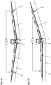
- FIG. 3a and Fig. 3b each illustrate a rear view of a spray boom 14 attached to the rear of the distributor 10 Fig. 3a this is initially pivoted symmetrically and guided along a bottom contour 56, and wherein in the Figure 3b this is only pivoted on the right-hand side in order to be guided along a floor contour 56.
- an actual value detection 60 in the form of distance sensors 64 is attached to each of the booms 28, which detects the actual distance of the spray boom 14 or the boom 28 to a ground contour.
- the determined values are then transmitted to a computer unit 62 and compared with a setpoint stored in the computer unit 62.
- the transmission can also take place wirelessly using a cable connection.
- the computer unit 62 first determines whether and in which direction, for example, the boom 28 must be pivoted. Lies, as in Fig.
- the two arms 28 with the actuator 42 and the coupling elements 44 are initially pivoted symmetrically to one another;
- the spray boom 14 is rotated via the suspension point or the rotary bearing 30.
- the rotation of the spray boom 14 takes place in turn as a function of the current position of the spray boom 14 from the actual value detection 60.
- the rotation of the spray boom 14 takes place as in FIG Figure 3b shown in the counterclockwise direction, although with a corresponding bottom contour 56 a clockwise rotation would of course also be possible.
- the rotation of the sprayer boom 14 takes place again until the position information determined by the actual value acquisition 60 again agrees with the setpoint values stored in the computer unit 62.
- the rotary bearing 30 could be provided with a rotary drive 32.
- This rotary drive 32 can in turn be controlled by the computer unit 62.
- Driving situations can arise in which the machine, for example with a boom (for example the right boom), passes an obstacle such as a post, a well or the like and would touch it without manual control intervention.
- the boom that does not approach an obstacle is still controlled in its position with the automatic boom control, whereby initially both booms can be aligned parallel or horizontally (cf. Fig. 1 ).
- the driver intervenes in the boom control, for example by pressing a button. This temporarily deactivates the automatic mode for the right-hand side so that the driver can position the boom, ie lift it, so that he can pass the obstacle without collisions.
- Such a situation is shown, for example, in the schematic view of FIG Figure 3b shown.
- the driver influences the computer unit 62 by manual command so that it ensures that the right boom 28 is raised.
- the respective boom 28 (here the right one) remains in the last set raised position (cf. Figure 3b ).
- the driver can return to the automatic mode by means of appropriate operator input (eg pressing a button), whereby the boom positions are again defined by the automatic control.
- appropriate operator input eg pressing a button
- FIG. 3b it is possible for the operator to manually superimpose the control on one side (ie one side of the entire boom 28).
- the automatic height control can be deactivated on one side, for example, by pressing a button.
- the user can thus manually control the deactivated boom with one or the same button into a desired position, for example over an obstacle.
- the deactivated boom is regulated or held by the regulation to a type of "artificial horizon". This "artificial horizon" relates to the vehicle in the long term. Brief rolling movements are not taken into account, long-term changes such as a side slope are followed by the horizon.
- boom control is deactivated on one side (here on the right in Figure 3b ) and the operator does not press any other key, the respective page remains in its current position.
- the second boom side continues to regulate in normal control mode. Only after a specific key has been deliberately pressed or after a set dwell time does the deactivated boom side return to automatic mode.
- the method can provide for a symmetrical lifting of both extension arms 28, after which the entire linkage can be pivoted about the central horizontal axis of rotation, so that the result is the same as with a one-sided manually specified lifting only one arm 28.
Landscapes
- Life Sciences & Earth Sciences (AREA)
- Engineering & Computer Science (AREA)
- Insects & Arthropods (AREA)
- Pest Control & Pesticides (AREA)
- Wood Science & Technology (AREA)
- Zoology (AREA)
- Environmental Sciences (AREA)
- Catching Or Destruction (AREA)
- Special Spraying Apparatus (AREA)
Applications Claiming Priority (4)
| Application Number | Priority Date | Filing Date | Title |
|---|---|---|---|
| DE102013109086 | 2013-08-22 | ||
| DE102013222803 | 2013-11-09 | ||
| PCT/EP2014/067854 WO2015025015A1 (fr) | 2013-08-22 | 2014-08-21 | Procédé de commande de mouvement et/ou de réglage d'un dispositif de distribution |
| EP14753103.2A EP3035794B1 (fr) | 2013-08-22 | 2014-08-21 | Procédé de commande de mouvement et/ou de réglage d'un dispositif de distribution |
Related Parent Applications (1)
| Application Number | Title | Priority Date | Filing Date |
|---|---|---|---|
| EP14753103.2A Division EP3035794B1 (fr) | 2013-08-22 | 2014-08-21 | Procédé de commande de mouvement et/ou de réglage d'un dispositif de distribution |
Publications (2)
| Publication Number | Publication Date |
|---|---|
| EP3912468A1 true EP3912468A1 (fr) | 2021-11-24 |
| EP3912468B1 EP3912468B1 (fr) | 2024-04-03 |
Family
ID=51383736
Family Applications (2)
| Application Number | Title | Priority Date | Filing Date |
|---|---|---|---|
| EP21186103.4A Active EP3912468B1 (fr) | 2013-08-22 | 2014-08-21 | Procédé de commande et/ou de réglage du mouvement d'un dispositif d'épandage agricole |
| EP14753103.2A Active EP3035794B1 (fr) | 2013-08-22 | 2014-08-21 | Procédé de commande de mouvement et/ou de réglage d'un dispositif de distribution |
Family Applications After (1)
| Application Number | Title | Priority Date | Filing Date |
|---|---|---|---|
| EP14753103.2A Active EP3035794B1 (fr) | 2013-08-22 | 2014-08-21 | Procédé de commande de mouvement et/ou de réglage d'un dispositif de distribution |
Country Status (3)
| Country | Link |
|---|---|
| EP (2) | EP3912468B1 (fr) |
| DK (2) | DK3912468T3 (fr) |
| WO (1) | WO2015025015A1 (fr) |
Families Citing this family (4)
| Publication number | Priority date | Publication date | Assignee | Title |
|---|---|---|---|---|
| DE102015102422A1 (de) * | 2015-02-20 | 2016-08-25 | Horsch Leeb Application Systems Gmbh | Verfahren zur Bewegungssteuerung und/oder Regelung einer landwirtschaftlichen Verteilvorrichtung |
| DE102015114451A1 (de) * | 2015-08-31 | 2017-03-02 | Amazonen-Werke H. Dreyer Gmbh & Co. Kg | Steuervorrichtung für eine landwirtschaftliche Maschine |
| DE102015119145A1 (de) | 2015-11-06 | 2017-05-11 | Amazonen-Werke H. Dreyer Gmbh & Co. Kg | Regel- und/oder Steuersystem für eine landwirtschaftliche Maschine |
| DE102016109513A1 (de) | 2016-05-24 | 2017-11-30 | Amazonen-Werke H. Dreyer Gmbh & Co. Kg | Regel- und/oder Steuersystem, landwirtschaftliche Maschine mit einem solchen System und Verfahren zum Betreiben einer landwirtschaftlichen Maschine |
Citations (6)
| Publication number | Priority date | Publication date | Assignee | Title |
|---|---|---|---|---|
| DE4140254A1 (de) * | 1991-10-22 | 1993-06-09 | Gerd E. F. 8608 Memmelsdorf De Steffen | Ultraschallgefuehrte spritze fuer die landwirtschaft |
| FR2690811A1 (fr) * | 1991-06-21 | 1993-11-12 | Matrot Louis | Suspension perfectionnée de rampe de pulvérisateur. |
| FR2734499A1 (fr) * | 1995-05-24 | 1996-11-29 | Agrotronix Sa | Procede de reglage en position d'une rampe de pulverisation |
| EP2186405A1 (fr) | 2008-11-12 | 2010-05-19 | Leeb Mechanik GmbH | Tige de pulvérisation et son procédé de commande |
| FR2965454A1 (fr) * | 2010-10-05 | 2012-04-06 | Exel Ind | Engin agricole de pulverisation et procede de pulverisation d'un liquide phytosanitaire sur un terrain cultive au moyen d'un tel engin |
| EP2591657A1 (fr) | 2011-11-08 | 2013-05-15 | HORSCH LEEB Application Systems GmbH | Dispositif mobile destiné à sortir des agents actifs liquides et/ou solides et procédé de commande du dispositif |
-
2014
- 2014-08-21 EP EP21186103.4A patent/EP3912468B1/fr active Active
- 2014-08-21 DK DK21186103.4T patent/DK3912468T3/da active
- 2014-08-21 EP EP14753103.2A patent/EP3035794B1/fr active Active
- 2014-08-21 DK DK14753103.2T patent/DK3035794T3/da active
- 2014-08-21 WO PCT/EP2014/067854 patent/WO2015025015A1/fr not_active Ceased
Patent Citations (6)
| Publication number | Priority date | Publication date | Assignee | Title |
|---|---|---|---|---|
| FR2690811A1 (fr) * | 1991-06-21 | 1993-11-12 | Matrot Louis | Suspension perfectionnée de rampe de pulvérisateur. |
| DE4140254A1 (de) * | 1991-10-22 | 1993-06-09 | Gerd E. F. 8608 Memmelsdorf De Steffen | Ultraschallgefuehrte spritze fuer die landwirtschaft |
| FR2734499A1 (fr) * | 1995-05-24 | 1996-11-29 | Agrotronix Sa | Procede de reglage en position d'une rampe de pulverisation |
| EP2186405A1 (fr) | 2008-11-12 | 2010-05-19 | Leeb Mechanik GmbH | Tige de pulvérisation et son procédé de commande |
| FR2965454A1 (fr) * | 2010-10-05 | 2012-04-06 | Exel Ind | Engin agricole de pulverisation et procede de pulverisation d'un liquide phytosanitaire sur un terrain cultive au moyen d'un tel engin |
| EP2591657A1 (fr) | 2011-11-08 | 2013-05-15 | HORSCH LEEB Application Systems GmbH | Dispositif mobile destiné à sortir des agents actifs liquides et/ou solides et procédé de commande du dispositif |
Also Published As
| Publication number | Publication date |
|---|---|
| DK3035794T3 (da) | 2021-09-20 |
| WO2015025015A1 (fr) | 2015-02-26 |
| EP3035794A1 (fr) | 2016-06-29 |
| EP3912468B1 (fr) | 2024-04-03 |
| EP3035794B1 (fr) | 2021-08-11 |
| DK3912468T3 (da) | 2024-05-27 |
Similar Documents
| Publication | Publication Date | Title |
|---|---|---|
| EP3058820B1 (fr) | Procede de commande et/ou de reglage de mouvement d'un dispositif de distribution agricole | |
| EP2186405B1 (fr) | Tige de pulvérisation et son procédé de commande | |
| EP3219187B1 (fr) | Dispositif mobile destiné à sortir des agents actifs liquides et/ou solides et procédé de commande du dispositif | |
| EP2829177B1 (fr) | Épandeuse agricole équipée d'un dispositif d'épandage et système de commande du dispositif d'épandage | |
| EP2839740B1 (fr) | Procédé de commande de mouvement et/ou de réglage d'un dispositif d'épandage agricole | |
| EP2837285B1 (fr) | Rampe de pulvérisation d'un pulvérisateur agricole | |
| EP1405556A2 (fr) | Faucheuse automoteur à grande largeur de travail | |
| EP3035794B1 (fr) | Procédé de commande de mouvement et/ou de réglage d'un dispositif de distribution | |
| EP3308644B1 (fr) | Système de commande et/ou de réglage d'une machine agricole | |
| DE102020118528A1 (de) | Landwirtschaftliche Verteilmaschine, vorzugsweise eine Feldspritze oder ein Düngerstreuer | |
| EP3141114B1 (fr) | Systeme d'epandage et procede d'epandage | |
| EP3804516B1 (fr) | Machine d'épandage agricole, de préférence pulvérisateur ou distributeur d'engrais | |
| EP3469898B1 (fr) | Machine d'épandage agricole et procédé de commande d'une telle machine d'épandage | |
| EP3732945A1 (fr) | Technique de la génération d'un profil de terrain à l'aide d'une machine agricole | |
| EP3592142B1 (fr) | Dispositif de régulation, véhicule utilitaire agricole et procédé de régulation d'un véhicule utilitaire agricole | |
| EP3437470A1 (fr) | Pulvérisateur agricole et bras de pulvérisateur pour un pulvérisateur agricole | |
| EP3466257B1 (fr) | Machine d'épandage agricole et procédé de commande d'une telle machine d'épandage | |
| EP3305071A1 (fr) | Système de commande, véhicule agricole et procédé de commande d'un véhicule agricole | |
| EP3469897B1 (fr) | Machine d'épandage agricole et procédé de commande d'une telle machine d'épandage | |
| EP4477046A1 (fr) | Structure porteuse pour un outil agricole destinée à l'épandage d'un produit agricole sur un sol, outil doté d'une structure porteuse et procédé d'épandage d'un produit agricole | |
| DE10011734A1 (de) | Verfahren zum Betreiben eines Spritzgeräts und Vorrichtung zum Steuern oder Regeln des Betriebs eines Spritzgeräts | |
| WO2023144105A1 (fr) | Procédé, unité de commande et système de commande pour une commande de système d'ascenseur électro-hydraulique |
Legal Events
| Date | Code | Title | Description |
|---|---|---|---|
| PUAI | Public reference made under article 153(3) epc to a published international application that has entered the european phase |
Free format text: ORIGINAL CODE: 0009012 |
|
| STAA | Information on the status of an ep patent application or granted ep patent |
Free format text: STATUS: THE APPLICATION HAS BEEN PUBLISHED |
|
| AC | Divisional application: reference to earlier application |
Ref document number: 3035794 Country of ref document: EP Kind code of ref document: P |
|
| AK | Designated contracting states |
Kind code of ref document: A1 Designated state(s): AL AT BE BG CH CY CZ DE DK EE ES FI FR GB GR HR HU IE IS IT LI LT LU LV MC MK MT NL NO PL PT RO RS SE SI SK SM TR |
|
| B565 | Issuance of search results under rule 164(2) epc |
Effective date: 20211026 |
|
| STAA | Information on the status of an ep patent application or granted ep patent |
Free format text: STATUS: REQUEST FOR EXAMINATION WAS MADE |
|
| 17P | Request for examination filed |
Effective date: 20220523 |
|
| RBV | Designated contracting states (corrected) |
Designated state(s): AL AT BE BG CH CY CZ DE DK EE ES FI FR GB GR HR HU IE IS IT LI LT LU LV MC MK MT NL NO PL PT RO RS SE SI SK SM TR |
|
| GRAP | Despatch of communication of intention to grant a patent |
Free format text: ORIGINAL CODE: EPIDOSNIGR1 |
|
| STAA | Information on the status of an ep patent application or granted ep patent |
Free format text: STATUS: GRANT OF PATENT IS INTENDED |
|
| INTG | Intention to grant announced |
Effective date: 20240122 |
|
| GRAS | Grant fee paid |
Free format text: ORIGINAL CODE: EPIDOSNIGR3 |
|
| GRAA | (expected) grant |
Free format text: ORIGINAL CODE: 0009210 |
|
| STAA | Information on the status of an ep patent application or granted ep patent |
Free format text: STATUS: THE PATENT HAS BEEN GRANTED |
|
| AC | Divisional application: reference to earlier application |
Ref document number: 3035794 Country of ref document: EP Kind code of ref document: P |
|
| AK | Designated contracting states |
Kind code of ref document: B1 Designated state(s): AL AT BE BG CH CY CZ DE DK EE ES FI FR GB GR HR HU IE IS IT LI LT LU LV MC MK MT NL NO PL PT RO RS SE SI SK SM TR |
|
| REG | Reference to a national code |
Ref country code: CH Ref legal event code: EP |
|
| REG | Reference to a national code |
Ref country code: IE Ref legal event code: FG4D Free format text: LANGUAGE OF EP DOCUMENT: GERMAN |
|
| REG | Reference to a national code |
Ref country code: DE Ref legal event code: R096 Ref document number: 502014016801 Country of ref document: DE |
|
| REG | Reference to a national code |
Ref country code: DK Ref legal event code: T3 Effective date: 20240523 |
|
| P01 | Opt-out of the competence of the unified patent court (upc) registered |
Effective date: 20240513 |
|
| REG | Reference to a national code |
Ref country code: NL Ref legal event code: FP |
|
| REG | Reference to a national code |
Ref country code: LT Ref legal event code: MG9D |
|
| PG25 | Lapsed in a contracting state [announced via postgrant information from national office to epo] |
Ref country code: IS Free format text: LAPSE BECAUSE OF FAILURE TO SUBMIT A TRANSLATION OF THE DESCRIPTION OR TO PAY THE FEE WITHIN THE PRESCRIBED TIME-LIMIT Effective date: 20240803 |
|
| PG25 | Lapsed in a contracting state [announced via postgrant information from national office to epo] |
Ref country code: BG Free format text: LAPSE BECAUSE OF FAILURE TO SUBMIT A TRANSLATION OF THE DESCRIPTION OR TO PAY THE FEE WITHIN THE PRESCRIBED TIME-LIMIT Effective date: 20240403 |
|
| PG25 | Lapsed in a contracting state [announced via postgrant information from national office to epo] |
Ref country code: HR Free format text: LAPSE BECAUSE OF FAILURE TO SUBMIT A TRANSLATION OF THE DESCRIPTION OR TO PAY THE FEE WITHIN THE PRESCRIBED TIME-LIMIT Effective date: 20240403 Ref country code: FI Free format text: LAPSE BECAUSE OF FAILURE TO SUBMIT A TRANSLATION OF THE DESCRIPTION OR TO PAY THE FEE WITHIN THE PRESCRIBED TIME-LIMIT Effective date: 20240403 |
|
| PG25 | Lapsed in a contracting state [announced via postgrant information from national office to epo] |
Ref country code: GR Free format text: LAPSE BECAUSE OF FAILURE TO SUBMIT A TRANSLATION OF THE DESCRIPTION OR TO PAY THE FEE WITHIN THE PRESCRIBED TIME-LIMIT Effective date: 20240704 |
|
| PG25 | Lapsed in a contracting state [announced via postgrant information from national office to epo] |
Ref country code: PT Free format text: LAPSE BECAUSE OF FAILURE TO SUBMIT A TRANSLATION OF THE DESCRIPTION OR TO PAY THE FEE WITHIN THE PRESCRIBED TIME-LIMIT Effective date: 20240805 |
|
| PG25 | Lapsed in a contracting state [announced via postgrant information from national office to epo] |
Ref country code: ES Free format text: LAPSE BECAUSE OF FAILURE TO SUBMIT A TRANSLATION OF THE DESCRIPTION OR TO PAY THE FEE WITHIN THE PRESCRIBED TIME-LIMIT Effective date: 20240403 |
|
| PG25 | Lapsed in a contracting state [announced via postgrant information from national office to epo] |
Ref country code: CZ Free format text: LAPSE BECAUSE OF FAILURE TO SUBMIT A TRANSLATION OF THE DESCRIPTION OR TO PAY THE FEE WITHIN THE PRESCRIBED TIME-LIMIT Effective date: 20240403 |
|
| PG25 | Lapsed in a contracting state [announced via postgrant information from national office to epo] |
Ref country code: PL Free format text: LAPSE BECAUSE OF FAILURE TO SUBMIT A TRANSLATION OF THE DESCRIPTION OR TO PAY THE FEE WITHIN THE PRESCRIBED TIME-LIMIT Effective date: 20240403 |
|
| PG25 | Lapsed in a contracting state [announced via postgrant information from national office to epo] |
Ref country code: LV Free format text: LAPSE BECAUSE OF FAILURE TO SUBMIT A TRANSLATION OF THE DESCRIPTION OR TO PAY THE FEE WITHIN THE PRESCRIBED TIME-LIMIT Effective date: 20240403 |
|
| PG25 | Lapsed in a contracting state [announced via postgrant information from national office to epo] |
Ref country code: PT Free format text: LAPSE BECAUSE OF FAILURE TO SUBMIT A TRANSLATION OF THE DESCRIPTION OR TO PAY THE FEE WITHIN THE PRESCRIBED TIME-LIMIT Effective date: 20240805 Ref country code: PL Free format text: LAPSE BECAUSE OF FAILURE TO SUBMIT A TRANSLATION OF THE DESCRIPTION OR TO PAY THE FEE WITHIN THE PRESCRIBED TIME-LIMIT Effective date: 20240403 Ref country code: NO Free format text: LAPSE BECAUSE OF FAILURE TO SUBMIT A TRANSLATION OF THE DESCRIPTION OR TO PAY THE FEE WITHIN THE PRESCRIBED TIME-LIMIT Effective date: 20240703 Ref country code: LV Free format text: LAPSE BECAUSE OF FAILURE TO SUBMIT A TRANSLATION OF THE DESCRIPTION OR TO PAY THE FEE WITHIN THE PRESCRIBED TIME-LIMIT Effective date: 20240403 Ref country code: IS Free format text: LAPSE BECAUSE OF FAILURE TO SUBMIT A TRANSLATION OF THE DESCRIPTION OR TO PAY THE FEE WITHIN THE PRESCRIBED TIME-LIMIT Effective date: 20240803 Ref country code: HR Free format text: LAPSE BECAUSE OF FAILURE TO SUBMIT A TRANSLATION OF THE DESCRIPTION OR TO PAY THE FEE WITHIN THE PRESCRIBED TIME-LIMIT Effective date: 20240403 Ref country code: GR Free format text: LAPSE BECAUSE OF FAILURE TO SUBMIT A TRANSLATION OF THE DESCRIPTION OR TO PAY THE FEE WITHIN THE PRESCRIBED TIME-LIMIT Effective date: 20240704 Ref country code: FI Free format text: LAPSE BECAUSE OF FAILURE TO SUBMIT A TRANSLATION OF THE DESCRIPTION OR TO PAY THE FEE WITHIN THE PRESCRIBED TIME-LIMIT Effective date: 20240403 Ref country code: ES Free format text: LAPSE BECAUSE OF FAILURE TO SUBMIT A TRANSLATION OF THE DESCRIPTION OR TO PAY THE FEE WITHIN THE PRESCRIBED TIME-LIMIT Effective date: 20240403 Ref country code: CZ Free format text: LAPSE BECAUSE OF FAILURE TO SUBMIT A TRANSLATION OF THE DESCRIPTION OR TO PAY THE FEE WITHIN THE PRESCRIBED TIME-LIMIT Effective date: 20240403 Ref country code: BG Free format text: LAPSE BECAUSE OF FAILURE TO SUBMIT A TRANSLATION OF THE DESCRIPTION OR TO PAY THE FEE WITHIN THE PRESCRIBED TIME-LIMIT Effective date: 20240403 Ref country code: RS Free format text: LAPSE BECAUSE OF FAILURE TO SUBMIT A TRANSLATION OF THE DESCRIPTION OR TO PAY THE FEE WITHIN THE PRESCRIBED TIME-LIMIT Effective date: 20240703 |
|
| REG | Reference to a national code |
Ref country code: DE Ref legal event code: R097 Ref document number: 502014016801 Country of ref document: DE |
|
| PG25 | Lapsed in a contracting state [announced via postgrant information from national office to epo] |
Ref country code: EE Free format text: LAPSE BECAUSE OF FAILURE TO SUBMIT A TRANSLATION OF THE DESCRIPTION OR TO PAY THE FEE WITHIN THE PRESCRIBED TIME-LIMIT Effective date: 20240403 |
|
| PG25 | Lapsed in a contracting state [announced via postgrant information from national office to epo] |
Ref country code: RO Free format text: LAPSE BECAUSE OF FAILURE TO SUBMIT A TRANSLATION OF THE DESCRIPTION OR TO PAY THE FEE WITHIN THE PRESCRIBED TIME-LIMIT Effective date: 20240403 Ref country code: SK Free format text: LAPSE BECAUSE OF FAILURE TO SUBMIT A TRANSLATION OF THE DESCRIPTION OR TO PAY THE FEE WITHIN THE PRESCRIBED TIME-LIMIT Effective date: 20240403 |
|
| PG25 | Lapsed in a contracting state [announced via postgrant information from national office to epo] |
Ref country code: SM Free format text: LAPSE BECAUSE OF FAILURE TO SUBMIT A TRANSLATION OF THE DESCRIPTION OR TO PAY THE FEE WITHIN THE PRESCRIBED TIME-LIMIT Effective date: 20240403 |
|
| PG25 | Lapsed in a contracting state [announced via postgrant information from national office to epo] |
Ref country code: SM Free format text: LAPSE BECAUSE OF FAILURE TO SUBMIT A TRANSLATION OF THE DESCRIPTION OR TO PAY THE FEE WITHIN THE PRESCRIBED TIME-LIMIT Effective date: 20240403 Ref country code: SK Free format text: LAPSE BECAUSE OF FAILURE TO SUBMIT A TRANSLATION OF THE DESCRIPTION OR TO PAY THE FEE WITHIN THE PRESCRIBED TIME-LIMIT Effective date: 20240403 Ref country code: RO Free format text: LAPSE BECAUSE OF FAILURE TO SUBMIT A TRANSLATION OF THE DESCRIPTION OR TO PAY THE FEE WITHIN THE PRESCRIBED TIME-LIMIT Effective date: 20240403 Ref country code: EE Free format text: LAPSE BECAUSE OF FAILURE TO SUBMIT A TRANSLATION OF THE DESCRIPTION OR TO PAY THE FEE WITHIN THE PRESCRIBED TIME-LIMIT Effective date: 20240403 |
|
| PLBE | No opposition filed within time limit |
Free format text: ORIGINAL CODE: 0009261 |
|
| STAA | Information on the status of an ep patent application or granted ep patent |
Free format text: STATUS: NO OPPOSITION FILED WITHIN TIME LIMIT |
|
| 26N | No opposition filed |
Effective date: 20250106 |
|
| REG | Reference to a national code |
Ref country code: CH Ref legal event code: PL |
|
| PG25 | Lapsed in a contracting state [announced via postgrant information from national office to epo] |
Ref country code: LU Free format text: LAPSE BECAUSE OF NON-PAYMENT OF DUE FEES Effective date: 20240821 |
|
| PG25 | Lapsed in a contracting state [announced via postgrant information from national office to epo] |
Ref country code: MC Free format text: LAPSE BECAUSE OF FAILURE TO SUBMIT A TRANSLATION OF THE DESCRIPTION OR TO PAY THE FEE WITHIN THE PRESCRIBED TIME-LIMIT Effective date: 20240403 Ref country code: SI Free format text: LAPSE BECAUSE OF FAILURE TO SUBMIT A TRANSLATION OF THE DESCRIPTION OR TO PAY THE FEE WITHIN THE PRESCRIBED TIME-LIMIT Effective date: 20240403 Ref country code: CH Free format text: LAPSE BECAUSE OF NON-PAYMENT OF DUE FEES Effective date: 20240831 |
|
| REG | Reference to a national code |
Ref country code: BE Ref legal event code: MM Effective date: 20240831 |
|
| PG25 | Lapsed in a contracting state [announced via postgrant information from national office to epo] |
Ref country code: BE Free format text: LAPSE BECAUSE OF NON-PAYMENT OF DUE FEES Effective date: 20240831 |
|
| PG25 | Lapsed in a contracting state [announced via postgrant information from national office to epo] |
Ref country code: IE Free format text: LAPSE BECAUSE OF NON-PAYMENT OF DUE FEES Effective date: 20240821 |
|
| PG25 | Lapsed in a contracting state [announced via postgrant information from national office to epo] |
Ref country code: SE Free format text: LAPSE BECAUSE OF FAILURE TO SUBMIT A TRANSLATION OF THE DESCRIPTION OR TO PAY THE FEE WITHIN THE PRESCRIBED TIME-LIMIT Effective date: 20240403 |
|
| PGFP | Annual fee paid to national office [announced via postgrant information from national office to epo] |
Ref country code: NL Payment date: 20250821 Year of fee payment: 12 |
|
| PGFP | Annual fee paid to national office [announced via postgrant information from national office to epo] |
Ref country code: DE Payment date: 20250819 Year of fee payment: 12 Ref country code: DK Payment date: 20250821 Year of fee payment: 12 |
|
| REG | Reference to a national code |
Ref country code: AT Ref legal event code: MM01 Ref document number: 1671193 Country of ref document: AT Kind code of ref document: T Effective date: 20240821 |
|
| PGFP | Annual fee paid to national office [announced via postgrant information from national office to epo] |
Ref country code: GB Payment date: 20250822 Year of fee payment: 12 |
|
| PG25 | Lapsed in a contracting state [announced via postgrant information from national office to epo] |
Ref country code: AT Free format text: LAPSE BECAUSE OF NON-PAYMENT OF DUE FEES Effective date: 20240821 |
|
| PGFP | Annual fee paid to national office [announced via postgrant information from national office to epo] |
Ref country code: FR Payment date: 20250821 Year of fee payment: 12 |
|
| PG25 | Lapsed in a contracting state [announced via postgrant information from national office to epo] |
Ref country code: IT Free format text: LAPSE BECAUSE OF FAILURE TO SUBMIT A TRANSLATION OF THE DESCRIPTION OR TO PAY THE FEE WITHIN THE PRESCRIBED TIME-LIMIT Effective date: 20240403 Ref country code: CY Free format text: LAPSE BECAUSE OF FAILURE TO SUBMIT A TRANSLATION OF THE DESCRIPTION OR TO PAY THE FEE WITHIN THE PRESCRIBED TIME-LIMIT; INVALID AB INITIO Effective date: 20140821 |
|
| PG25 | Lapsed in a contracting state [announced via postgrant information from national office to epo] |
Ref country code: HU Free format text: LAPSE BECAUSE OF FAILURE TO SUBMIT A TRANSLATION OF THE DESCRIPTION OR TO PAY THE FEE WITHIN THE PRESCRIBED TIME-LIMIT; INVALID AB INITIO Effective date: 20140821 |
|
| REG | Reference to a national code |
Ref country code: DE Ref legal event code: R081 Ref document number: 502014016801 Country of ref document: DE Owner name: HORSCH LEEB APPLICATION SYSTEMS SE & CO. KG, DE Free format text: FORMER OWNER: HORSCH LEEB APPLICATION SYSTEMS GMBH, 94405 LANDAU, DE |