EP3912607B1 - Procédé de fourniture des données de commande pour un laser chirurgical ophtalmique d'un dispositif de traitement - Google Patents
Procédé de fourniture des données de commande pour un laser chirurgical ophtalmique d'un dispositif de traitement Download PDFInfo
- Publication number
- EP3912607B1 EP3912607B1 EP21175004.7A EP21175004A EP3912607B1 EP 3912607 B1 EP3912607 B1 EP 3912607B1 EP 21175004 A EP21175004 A EP 21175004A EP 3912607 B1 EP3912607 B1 EP 3912607B1
- Authority
- EP
- European Patent Office
- Prior art keywords
- lenticule
- correction value
- deformation
- height
- geometry
- Prior art date
- Legal status (The legal status is an assumption and is not a legal conclusion. Google has not performed a legal analysis and makes no representation as to the accuracy of the status listed.)
- Active
Links
Images

Classifications
-
- A—HUMAN NECESSITIES
- A61—MEDICAL OR VETERINARY SCIENCE; HYGIENE
- A61F—FILTERS IMPLANTABLE INTO BLOOD VESSELS; PROSTHESES; DEVICES PROVIDING PATENCY TO, OR PREVENTING COLLAPSING OF, TUBULAR STRUCTURES OF THE BODY, e.g. STENTS; ORTHOPAEDIC, NURSING OR CONTRACEPTIVE DEVICES; FOMENTATION; TREATMENT OR PROTECTION OF EYES OR EARS; BANDAGES, DRESSINGS OR ABSORBENT PADS; FIRST-AID KITS
- A61F9/00—Methods or devices for treatment of the eyes; Devices for putting in contact-lenses; Devices to correct squinting; Apparatus to guide the blind; Protective devices for the eyes, carried on the body or in the hand
- A61F9/007—Methods or devices for eye surgery
- A61F9/008—Methods or devices for eye surgery using laser
- A61F9/00825—Methods or devices for eye surgery using laser for photodisruption
- A61F9/00827—Refractive correction, e.g. lenticle
-
- A—HUMAN NECESSITIES
- A61—MEDICAL OR VETERINARY SCIENCE; HYGIENE
- A61F—FILTERS IMPLANTABLE INTO BLOOD VESSELS; PROSTHESES; DEVICES PROVIDING PATENCY TO, OR PREVENTING COLLAPSING OF, TUBULAR STRUCTURES OF THE BODY, e.g. STENTS; ORTHOPAEDIC, NURSING OR CONTRACEPTIVE DEVICES; FOMENTATION; TREATMENT OR PROTECTION OF EYES OR EARS; BANDAGES, DRESSINGS OR ABSORBENT PADS; FIRST-AID KITS
- A61F9/00—Methods or devices for treatment of the eyes; Devices for putting in contact-lenses; Devices to correct squinting; Apparatus to guide the blind; Protective devices for the eyes, carried on the body or in the hand
- A61F9/007—Methods or devices for eye surgery
- A61F9/008—Methods or devices for eye surgery using laser
-
- A—HUMAN NECESSITIES
- A61—MEDICAL OR VETERINARY SCIENCE; HYGIENE
- A61F—FILTERS IMPLANTABLE INTO BLOOD VESSELS; PROSTHESES; DEVICES PROVIDING PATENCY TO, OR PREVENTING COLLAPSING OF, TUBULAR STRUCTURES OF THE BODY, e.g. STENTS; ORTHOPAEDIC, NURSING OR CONTRACEPTIVE DEVICES; FOMENTATION; TREATMENT OR PROTECTION OF EYES OR EARS; BANDAGES, DRESSINGS OR ABSORBENT PADS; FIRST-AID KITS
- A61F9/00—Methods or devices for treatment of the eyes; Devices for putting in contact-lenses; Devices to correct squinting; Apparatus to guide the blind; Protective devices for the eyes, carried on the body or in the hand
- A61F9/007—Methods or devices for eye surgery
- A61F9/008—Methods or devices for eye surgery using laser
- A61F9/009—Auxiliary devices making contact with the eyeball and coupling in laser light, e.g. goniolenses
-
- A—HUMAN NECESSITIES
- A61—MEDICAL OR VETERINARY SCIENCE; HYGIENE
- A61B—DIAGNOSIS; SURGERY; IDENTIFICATION
- A61B18/00—Surgical instruments, devices or methods for transferring non-mechanical forms of energy to or from the body
- A61B2018/00636—Sensing and controlling the application of energy
- A61B2018/00696—Controlled or regulated parameters
- A61B2018/00726—Duty cycle
-
- A—HUMAN NECESSITIES
- A61—MEDICAL OR VETERINARY SCIENCE; HYGIENE
- A61B—DIAGNOSIS; SURGERY; IDENTIFICATION
- A61B18/00—Surgical instruments, devices or methods for transferring non-mechanical forms of energy to or from the body
- A61B2018/00636—Sensing and controlling the application of energy
- A61B2018/00696—Controlled or regulated parameters
- A61B2018/00761—Duration
-
- A—HUMAN NECESSITIES
- A61—MEDICAL OR VETERINARY SCIENCE; HYGIENE
- A61F—FILTERS IMPLANTABLE INTO BLOOD VESSELS; PROSTHESES; DEVICES PROVIDING PATENCY TO, OR PREVENTING COLLAPSING OF, TUBULAR STRUCTURES OF THE BODY, e.g. STENTS; ORTHOPAEDIC, NURSING OR CONTRACEPTIVE DEVICES; FOMENTATION; TREATMENT OR PROTECTION OF EYES OR EARS; BANDAGES, DRESSINGS OR ABSORBENT PADS; FIRST-AID KITS
- A61F9/00—Methods or devices for treatment of the eyes; Devices for putting in contact-lenses; Devices to correct squinting; Apparatus to guide the blind; Protective devices for the eyes, carried on the body or in the hand
- A61F9/007—Methods or devices for eye surgery
- A61F9/008—Methods or devices for eye surgery using laser
- A61F2009/00861—Methods or devices for eye surgery using laser adapted for treatment at a particular location
- A61F2009/00872—Cornea
-
- A—HUMAN NECESSITIES
- A61—MEDICAL OR VETERINARY SCIENCE; HYGIENE
- A61F—FILTERS IMPLANTABLE INTO BLOOD VESSELS; PROSTHESES; DEVICES PROVIDING PATENCY TO, OR PREVENTING COLLAPSING OF, TUBULAR STRUCTURES OF THE BODY, e.g. STENTS; ORTHOPAEDIC, NURSING OR CONTRACEPTIVE DEVICES; FOMENTATION; TREATMENT OR PROTECTION OF EYES OR EARS; BANDAGES, DRESSINGS OR ABSORBENT PADS; FIRST-AID KITS
- A61F9/00—Methods or devices for treatment of the eyes; Devices for putting in contact-lenses; Devices to correct squinting; Apparatus to guide the blind; Protective devices for the eyes, carried on the body or in the hand
- A61F9/007—Methods or devices for eye surgery
- A61F9/008—Methods or devices for eye surgery using laser
- A61F2009/00878—Planning
-
- A—HUMAN NECESSITIES
- A61—MEDICAL OR VETERINARY SCIENCE; HYGIENE
- A61F—FILTERS IMPLANTABLE INTO BLOOD VESSELS; PROSTHESES; DEVICES PROVIDING PATENCY TO, OR PREVENTING COLLAPSING OF, TUBULAR STRUCTURES OF THE BODY, e.g. STENTS; ORTHOPAEDIC, NURSING OR CONTRACEPTIVE DEVICES; FOMENTATION; TREATMENT OR PROTECTION OF EYES OR EARS; BANDAGES, DRESSINGS OR ABSORBENT PADS; FIRST-AID KITS
- A61F9/00—Methods or devices for treatment of the eyes; Devices for putting in contact-lenses; Devices to correct squinting; Apparatus to guide the blind; Protective devices for the eyes, carried on the body or in the hand
- A61F9/007—Methods or devices for eye surgery
- A61F9/008—Methods or devices for eye surgery using laser
- A61F2009/00897—Scanning mechanisms or algorithms
-
- A—HUMAN NECESSITIES
- A61—MEDICAL OR VETERINARY SCIENCE; HYGIENE
- A61F—FILTERS IMPLANTABLE INTO BLOOD VESSELS; PROSTHESES; DEVICES PROVIDING PATENCY TO, OR PREVENTING COLLAPSING OF, TUBULAR STRUCTURES OF THE BODY, e.g. STENTS; ORTHOPAEDIC, NURSING OR CONTRACEPTIVE DEVICES; FOMENTATION; TREATMENT OR PROTECTION OF EYES OR EARS; BANDAGES, DRESSINGS OR ABSORBENT PADS; FIRST-AID KITS
- A61F9/00—Methods or devices for treatment of the eyes; Devices for putting in contact-lenses; Devices to correct squinting; Apparatus to guide the blind; Protective devices for the eyes, carried on the body or in the hand
- A61F9/007—Methods or devices for eye surgery
- A61F9/008—Methods or devices for eye surgery using laser
- A61F9/00802—Methods or devices for eye surgery using laser for photoablation
- A61F9/00804—Refractive treatments
Definitions
- the present invention relates to a method for providing control data for an eye surgical laser of a treatment device for the separation of a lenticule.
- the invention also relates to a treatment device with at least one eye surgical laser and at least one control device for carrying out the method, a computer program and a computer-readable medium.
- Treatment devices and methods for controlling ophthalmological lasers to correct optical ametropia are known in the prior art.
- a pulsed laser and a beam focusing device can be designed such that laser beam pulses cause a photodisruption in a focus located within the organic material in order to separate a lenticule from the cornea to correct the ametropia.
- the eye is usually fixed by one or more contact elements of the treatment device.
- the contact element is a rigid element, for example a plano-concave lens, which is placed on the eye, in particular on the cornea, so that the eye is not moved during the treatment.
- the disadvantage of such a contact element is that a shape of the cornea cannot be exactly adapted to the contact element, as a result of which the cornea is deformed by the contact element. This can also change the shape of the lenticule to be separated, as a result of which treatment, in particular an achieved refractive power value, can be subject to errors.
- a user of the treatment device for example a doctor, can adapt a refractive power value to be corrected when planning the treatment according to his experience, so that despite the contact element, the refractive power value achieved is suitable for correcting the optical ametropia.
- an achieved lenticule height can deviate from a planned lenticule height, which can, for example, result in more tissue being removed from the cornea than necessary.
- a method for generating control data for an eye surgical treatment device is known, which is carried out by means of a Laser device in the cornea of the eye separates tissue layers, wherein during operation of the laser device a contact glass having a contact surface deforms the cornea into the shape of the contact surface, for which purpose the contact surface is first placed with a contact surface vertex on a corneal vertex and then pressed against it to deform the cornea.
- the control data for the laser device are generated in such a way that they specify coordinates of target points located in the cornea for the laser device, and when generating the target point coordinates, the deformation of the cornea, which occurs during operation of the laser device, is taken into account Contact glass is present.
- a device for generating control data for a laser device for the surgical correction of ametropia includes changing a curvature of a fundus of the eye by creating an incision in the cornea by radiating laser radiation into the cornea, the incision enclosing and isolating a volume of corneal tissue inside the cornea, and removing the enclosed volume of corneal tissue from the interior the cornea.
- the method includes making the incision that encloses and isolates the volume to include an anterior and a posterior portion, the anterior portion being at a constant distance from a corneal anterior surface, and wherein the curvature of the cornea of the eye is determined by different Removing the volume at least two radii r1 and r2 around the optical axis is changed.
- a treatment device for the surgical correction of ametropia of a patient's eye which has a laser device controlled by a control device, which separates corneal tissue by irradiating laser radiation, the control device using the laser device for focusing the laser radiation into the cornea in a pattern in the cornea lying target points and selects the pattern so that a volume is isolated in the cornea, the removal of which from the cornea brings about the desired correction of ametropia.
- the invention is based on the object of providing control data for controlling an eye surgical laser, in which compensation for a deformation of a lenticule that is generated by a contact element is provided in a simple manner.
- a first aspect of the invention relates to a method for providing control data of an eye surgical laser to a treatment device for the separation of a lenticule, the method having the following steps carried out by a control device.
- a control device is understood to mean a device, a device component or a device group that is set up to receive and evaluate signals and to provide, for example generate, control data.
- the control device can be designed, for example, as a control chip, computer program, computer program product or control device.
- the control device determines a lenticule geometry of the lenticule to be separated, which includes a lenticule height, from predetermined ametropia data of a human or animal eye, the lenticule geometry being defined by means of a refractive power value to be corrected and a lenticule diameter, and determining a correction value to compensate for a deformation of the Lenticule, which is generated by at least one contact element of the treatment device, the correction value being determined by means of at least one previous measurement of the treatment device.
- control device determines a deformation geometry of the lenticule, which includes a deformation height, the deformation geometry being defined by means of the refractive power value and a deformation diameter, the deformation diameter being calculated as a function of the lenticule diameter and the correction value.
- the control device ultimately provides control data for controlling the eye surgical laser, the control data using the deformation geometry to separate the steering pin.
- the lenticule geometry of the lenticule to be separated is first determined from previously determined ametropia data.
- the ametropia data can, for example, describe ametropia, i.e. a deviation of the refractive power of an eye or a cornea from the ideal value, for example short-sightedness, far-sightedness or blindness.
- the refractive error data can be used for For example, describe a value of a refractive power, i.e. a specification in diopters, or, for example, a deviation of astigmatism from a normal value.
- the ametropia data can be obtained, for example, by retrieving the ametropia data from a data storage or data server, or the ametropia data can be received, for example, from a measuring device that takes dimensions of the cornea and/or determines ametropia. Based on the ametropia data determined, the control device determines a lenticule geometry, which describes the dimensions of a lenticule and its position in the cornea. This means that the lenticule geometry, i.e.
- a lenticule is understood to be a solid body of the cornea, for example a disc-shaped disc that can be defined by anterior and posterior interfaces.
- the interfaces can, for example, form a biconvex, biconcave, concavo-convex, convex-concave, plane-parallel, plano-convex or plano-concave solid body.
- the control device can determine a correction value to compensate for a deformation of the lenticule, the deformation of the lenticule being generated by the contact element of the treatment device.
- the correction value is determined from at least one previous measurement by the treatment device. This means that the correction value is determined empirically from a previously carried out measurement with the treatment device.
- a deformation geometry of the lenticule can then be determined, for which purpose a deformation diameter is determined from the lenticule diameter and the correction value, by means of which the lenticule height to be corrected is achieved.
- the deformation geometry can then be determined from the refractive power value and the deformation diameter, which in particular describes the shape of the lenticule that is to be used to compensate for the deformation by the at least one contact element of the treatment device.
- the control data for controlling the eye surgical laser can be provided, which uses the deformation geometry to separate the lenticule instead of the lenticule geometry.
- the correction value is determined from a deviation in the lenticule height, which is expected according to the lenticule geometry, and an achieved lenticule height, the achieved lenticule height being determined after application of the treatment device without using the deformation geometry.
- the deviation that exists between the expected lenticule height, i.e. the planned lenticule height, and the achieved lenticule height when the deformation geometry is not used can be determined.
- the correction value can then be determined from this. For example, it may have been planned from the lenticule geometry that a lenticule height of 100 micrometers would be separated during the treatment, whereby lenticule height here means the maximum height of the lenticule. However, due to the deformation of the lenticule, for example, a lenticule height of 107 micrometers can be separated, whereby the refractive power value can have been adjusted manually beforehand. This would result in a deviation of 7 percent, with the correction value preferably being determined in such a way that this 7 percent deviation is compensated for.
- the measurement can preferably be carried out on artificial corneas and/or on animal corneas and/or on human donor corneas without using the deformation geometry. This has the advantage that the correction value can be determined using a simple measurement.
- This aspect of the invention results in the advantage that treatment results can be further improved, in particular a height of the lenticule to be separated can be correctly determined in order to compensate for deformation effects due to a contact element, for which purpose, for example, a manual adjustment of the refractive power value to be corrected can be carried out beforehand.
- a doctor can adjust the refractive power value before treatment based on his experience to compensate for the deformation by the contact element as usual and the method according to the invention additionally determines a coordinated deformation geometry of the lenticule, through which an amount of tissue to be removed from the cornea is optimized.
- the correction value is determined statistically from several previous measurements of the lenticule height and the achieved lenticule height, in particular by means of a linear regression.
- This has the advantage that the correction value becomes more robust against statistical deviations. For example, several measurements can be carried out, for example for several planned lenticule heights between 40 and 120 micrometers, which are compared with the lenticule heights achieved. Known statistical methods can be used for this, in particular a linear regression, the slope of which can represent the deviation between the lenticule heights.
- the lenticule height achieved is determined at at least two different times, the correction value being determined from an average of the deviations at the at least two different times.
- one of the times may be shortly after treatment, for example a day or a week after treatment, and the other time may be later, for example after a month.
- the lenticule height achieved at these two or more times can then be averaged in order to determine the deviation from the expected lenticule height, from which the correction value can then be determined. This has the advantage that the correction value becomes statistically more robust by using multiple measurements.
- the correction value is combined with a refractive power correction value, the refractive power correction value being determined from a deviation of the refractive power value to be corrected and an achieved refractive power value, in particular by means of a linear regression from several previous measurements and an average of refractive power value deviations from different ones Points in time, whereby the refractive power value achieved is determined after application of the treatment device.
- the correction value which is determined from a deviation of the expected and achieved lenticule height, can be combined with a refractive power correction value, wherein the refractive power correction value is determined from a deviation of the planned and achieved refractive power value.
- the refractive power correction value can preferably be determined using the same statistical methods as the correction value.
- This embodiment has the advantage that a deviation in the refractive power value can also be taken into account when determining the deformation geometry. Due to the deformation of the lenticule by the contact element, it is provided, for example, that the doctor adjusts the refractive power value based on empirical values in order to achieve compensation for the deformation. However, this adjustment of the refractive power value may not be optimal and there may still be a deviation from the refractive power value to be corrected to the achieved refractive power value, which can be determined from measurements with the treatment device.
- the refractive power correction value can be combined with the correction value by multiplying the correction value, for example, by the reciprocal of the refractive power correction value.
- the refractive power values can have an average deviation of 7 percent from one another, whereby this 7 percent can then be the refractive power correction value that is combined with the correction value.
- the correction value is preferably in a range from 0.7 to 1.5, in particular in a range from 1.0 to 1.4. This means that if a deviation of 10 percent was found between the lenticule height expected from the lenticule geometry and the determined lenticule height, the correction value can be 1.1. Together with the power correction value mentioned above, this would result in a total correction value of approximately 1.18.
- the deformation diameter is calculated by multiplying the lenticule diameter by a parameter that depends on the correction value, the parameter being determined using a theoretical lenticule geometry model, in particular using the Munnerlyn formula.
- the deformation diameter can be calculated from the lenticule diameter, that is, the planned lenticule diameter, by multiplying the lenticule diameter by a parameter, the parameter being dependent on the correction value.
- the parameter dependent on the correction value it is meant that it includes a mathematical calculation operation with the correction value, in particular a power of the correction value.
- the parameter dependent on the correction value can be determined from a lenticule geometry model, preferably from the lenticule geometry model through which the lenticule geometry is determined, for example using the Munnerlyn formula.
- a height is determined for the deformation height of the deformation geometry, which corresponds to a multiplication of the lenticule height by the reciprocal of the correction value, by calculating the deformation diameter by dividing the lenticule diameter by the square root of the correction value.
- the deformation height is reduced to a height that corresponds to the lenticule height divided by the correction value.
- the deformation diameter is determined by dividing the lenticule diameter by the "Correction value to the power of 1 ⁇ 2" is calculated.
- the square root of the correction value is obtained in particular from an analytical calculation of the lenticule geometry model, preferably from a calculation using the Munnerlyn formula.
- a second aspect of the present invention relates to a control device that is designed to carry out one of the methods described above.
- the control device can be designed, for example, as a control chip, control device or user program (“app”).
- the control device can preferably have a processor device and/or a data memory.
- a processor device is understood to mean a device or a device component for electronic data processing.
- the processor device can, for example, have at least one microcontroller and/or at least one microprocessor.
- a program code for carrying out the method according to the invention can preferably be stored on the optional data memory. The program code can then be designed, when executed by the processor device, to cause the control device to carry out one of the above-described embodiments of one or both methods according to the invention.
- a third aspect of the present invention relates to a treatment device with at least one eye surgical laser for the separation of a predefined corneal volume with predefined interfaces of a human or animal eye by means of photodisruption, and at least one control device for the laser or lasers, which is designed according to the steps of the method to carry out the first aspect of the invention.
- the treatment device according to the invention enables the disadvantages that occur when using conventional ablative treatment devices to be reliably reduced or even avoided.
- the laser can be suitable for producing laser pulses in a wavelength range between 300 nm and 1400 nm, preferably between 700 nm and 1200 nm, with a respective pulse duration between 1 fs and 1 ns, preferably between 10 fs and 10 ps, and a repetition frequency greater than 10 kilohertz (KHz), preferably between 100 KHz and 100 megahertz (MHz).
- KHz kilohertz
- MHz megahertz
- Such a femtosecond laser is particularly suitable for producing solid bodies within the cornea.
- the use of photodisruptive lasers in the method according to the invention also has the advantage that the cornea does not have to be irradiated in a wavelength range below 300 nm.
- Photodisruptive lasers of the type used here usually introduce pulsed laser radiation with a pulse duration between 1 fs and 1 ns into the corneal tissue.
- the power density of the respective laser pulse necessary for the optical breakthrough can be spatially limited, so that a high cutting precision is possible when producing the interfaces.
- the range between 700 nm and 780 nm can be selected as the wavelength range.
- control device can have at least one storage device for at least temporarily storing at least one control data set, the control data set or sets comprising control data for positioning and/or focusing individual laser pulses in the cornea/cornea; and can have at least one beam device for beam guidance and/or beam shaping and/or beam deflection and/or beam focusing of a laser beam of the laser.
- the control data sets mentioned are usually generated based on a measured topography and/or pachymetry and/or morphology of the cornea to be treated and the type of ametropia to be corrected.
- a fourth aspect of the invention relates to a computer program comprising commands which cause the treatment device according to the third aspect of the invention to carry out the method steps according to the first aspect of the invention and/or the method steps according to the second aspect of the invention.
- a fifth aspect of the invention relates to a computer-readable medium on which the computer program according to the fourth aspect of the invention is stored. Further features and their advantages can be found in the descriptions of the first to fourth aspects of the invention, with advantageous embodiments of each aspect of the invention being viewed as advantageous embodiments of the other aspect of the invention.
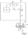
- the Figure 1 shows a schematic representation of a treatment device 10 with an eye surgical laser 18 for the separation of a cornea volume/corneal volume predefined by a lenticule geometry of a cornea of a human or animal eye 36, i.e. a lenticule 12, which can also be referred to as a solid body, with predefined ones Interfaces 14, 16 using photodisruption.
- a control device 20 can be designed for the laser 18, so that it emits pulsed laser pulses, for example in a predefined pattern, into the cornea of the eye 36, the determined interfaces 14, 16 of the lenticule 12 to be formed passing through the
- a predefined pattern can be created using photodisruption.
- the control device 20 can be a control device 20 that is external to the treatment device 10.
- the determined boundary surfaces 14, 16 form a lenticule 12 in the exemplary embodiment shown, the position of the lenticule 12 in this exemplary embodiment being chosen such that it can lie within a stroma 32 of the cornea, for example. Furthermore is over Figure 1 It can be seen that the so-called Bowman membrane 34 can be formed between the stroma 32 and an epithelium.
- the beam deflection device is also controlled by the control device 20 in order to generate the determined interfaces 14, 16, preferably also incisions or cuts 30, along predetermined incision courses.
- the laser 18 shown can preferably be a photodisruptive laser which is designed to emit laser pulses in a wavelength range between 300 nm and 1400 nm, preferably between 700 nm and 1200 nm, with a respective pulse duration between 1 fs and 1 ns, preferably between 10 fs and 10 ps, and a repetition frequency greater than 10 KHz, preferably between 100 KHz and 100 MHz.
- the control device 20 optionally also has a storage device (not shown) for at least temporarily storing at least one control data set, the control data set or sets comprising control data for positioning and/or focusing individual laser pulses in the cornea.
- the position data and/or focusing data of the individual laser pulses is generated based on predetermined ametropia data, in particular from a previously measured topography and/or pachymetry and/or the morphology of the cornea or the optical ametropia correction to be generated, for example generated within the stroma 32 of the eye 36.
- the control device 20 can, for example, receive the corresponding data from a data server, or the ametropia data can be determined as data input.
- the lenticule geometry of the lenticule 12 to be separated for correcting ametropia includes a lenticule height and is defined in particular by means of a refractive power value to be corrected, which can also be referred to as a planned refractive power value, and a lenticule diameter, which is also referred to as an optical zone.
- the lenticule height or lenticule thickness is a variable value that indicates the height of the lenticule in an anterior-posterior direction, that is, parallel to an optical axis of the eye 36, depending on a position perpendicular to the optical axis, in particular depending on a position in a radial direction of the lenticule.
- a precise course of the lenticule height depending on the position in the radial direction can be determined, for example, using a theoretical lenticule geometry model, in particular using the Munnerlyn formula.
- a contact element 28 can be provided, which can belong to the treatment device 10.
- the contact element 28 can also be provided separately from the treatment device 10.
- the contact element 28 can have a plano-concave lens, which is adapted to the eye 36 for fixation.
- the fixation by means of the contact element 28 can result in the cornea being deformed and thus the determined lenticule geometry for separating the lenticule 12 no longer optimally corresponds to the predetermined ametropia data. It can therefore happen that a planned or to be corrected lenticule height deviates from an achieved lenticule height after treatment with the treatment device 10.
- the deformation caused by the contact element 28 can result in the removed lenticule height not being optimal.
- an achieved lenticule height may be greater than required or planned. This means there would be more tissue from the cornea removed as required.
- This is, for example, in the scatterplot Figure 2 shown.
- the lenticule height (in micrometers) expected from the treatment is plotted on the x-axis and the lenticule height achieved (in micrometers) one day after the treatment is plotted on the y-axis.
- a linear regression line LR can have a slope of 1.07.
- the control device 20 carries out the method steps S1 to S4 described below, for example in Figure 3 are shown as a process diagram.
- step S1 the lenticule geometry of the lenticule 12 to be separated is determined from the predetermined refractive error data, the lenticule geometry being defined by means of the refractive power value to be corrected and the lenticule diameter.
- the refractive power value to be corrected can be adjusted by the doctor based on experience.
- a correction value for compensating for the deformation by the contact element 28 can be determined from at least one previous measurement with the treatment device 10.
- the correction value can be statistically derived from the measurements Figure 2 can be determined by using the slope of the regression line LR as a correction value, i.e. 1.07 in the example above.
- the numbers shown above are only intended to represent examples of the correction value and the correction value can be different, for example, depending on the treatment device and the associated contact element.
- a type of treatment i.e. depending on the refractive error data, and an adjustment of the refractive power value by the doctor can also change the correction value.
- the correction value can be in a range from 0.7 to 1.5, preferably in a range from 1.0 to 1.4.
- a deformation geometry of the lenticule 12 can be determined by the control device in step S3, whereby the refractive power value of the lenticule geometry, in particular the refractive power value that was set by the doctor, can be adopted for the deformation geometry.
- the lenticule diameter can be divided by a parameter dependent on the correction value, the parameter being determined using a theoretical lenticule geometry model.
- the lenticule geometry model can be the model by means of which the lenticule geometry was previously determined.
- Lenticle geometry model can be the Munnerlyn formula, where the parameter dependent on the correction value is the square root of the correction value.
- the deformation diameter is calculated by dividing the lenticule diameter with the square root of the correction value, i.e. in the example above with the root of 1.07. Consequently, a deformation height is determined using the deformation geometry, which corresponds to the lenticule height divided by the correction value.
- the deformation geometry determined in this way can then be provided by the control device 20 in a step S4 in the form of control data for controlling the ophthalmic surgical laser 18.
- the control data provided in this way which uses the deformation geometry to separate the lenticule 12, the deformation can be easily compensated for by the contact element 28, whereby a height of the lenticule 12 to be separated can be kept small. This allows treatment with the treatment device 10 to be improved.
Landscapes
- Health & Medical Sciences (AREA)
- Ophthalmology & Optometry (AREA)
- Optics & Photonics (AREA)
- Physics & Mathematics (AREA)
- Heart & Thoracic Surgery (AREA)
- Surgery (AREA)
- Engineering & Computer Science (AREA)
- Biomedical Technology (AREA)
- Nuclear Medicine, Radiotherapy & Molecular Imaging (AREA)
- Vascular Medicine (AREA)
- Life Sciences & Earth Sciences (AREA)
- Animal Behavior & Ethology (AREA)
- General Health & Medical Sciences (AREA)
- Public Health (AREA)
- Veterinary Medicine (AREA)
- Laser Surgery Devices (AREA)
Claims (13)
- Procédé pour fournir des données de commande d'un laser chirurgical ophtalmique (18) d'un dispositif de traitement (10) pour la séparation d'un lenticule (12), le procédé comportant les étapes suivantes réalisées par un dispositif de commande :déterminer (S1) une géométrie de lenticule du lenticule (12) à séparer, laquelle géométrie comprenant une hauteur de lenticule, à partir de données prédéterminées concernant un trouble visuel d'un oeil humain ou animal (36), la géométrie de lenticule étant définie au moyen d'une valeur de réfringence à corriger et d'un diamètre de lenticule ;déterminer (S2) une valeur de correction pour compenser une déformation du lenticule (12) qui est générée par au moins un élément de contact (28) du dispositif de traitement (10), la valeur de correction étant établie au moyen d'au moins une mesure précédente du dispositif de traitement (10) ;déterminer (S3) une géométrie de déformation du lenticule (12) comprenant une hauteur de déformation, la géométrie de déformation étant définie au moyen de la valeur de réfringence et d'un diamètre de déformation, le diamètre de déformation étant calculé en fonction du diamètre de lenticule et de la valeur de correction ;fournir (S4) des données de commande afin de commander le laser chirurgical ophtalmique (18), lesquelles données utilisent la géométrie de déformation pour séparer le lenticule (12),caractérisé en ce que la valeur de correction est déterminée à partir d'un écart de la hauteur de lenticule, qui est attendue en fonction de la géométrie de lenticule, et d'une hauteur de lenticule atteinte, la hauteur de lenticule atteinte étant déterminée après une application du dispositif de traitement (10) sans utiliser la géométrie de déformation.
- Procédé selon la revendication 1, caractérisé en ce que la valeur de correction est déterminée statistiquement à partir de plusieurs mesures précédentes de la hauteur de lenticule et de la hauteur de lenticule atteinte, en particulier au moyen d'une régression linéaire (LR).
- Procédé selon l'une des revendications précédentes, caractérisé en ce que la hauteur de lenticule atteinte est déterminée à au moins deux instants différents, la valeur de correction étant déterminée à partir d'une valeur moyenne des écarts aux au moins deux instants différents.
- Procédé selon l'une des revendications précédentes, caractérisé en ce que la valeur de correction est combinée avec une valeur de correction de valeur de réfringence, la valeur de correction de valeur de réfringence étant déterminée à partir d'un écart de la valeur de réfringence à corriger et d'une valeur de réfringence atteinte, en particulier au moyen d'une régression linéaire à partir de plusieurs mesures précédentes et d'une valeur moyenne d'écarts de valeur de réfringence à différents instants, la valeur de réfringence atteinte étant déterminée après une application du dispositif de traitement (10).
- Procédé selon l'une des revendications précédentes, caractérisé en ce que la valeur de correction est dans une plage de 0,7 à 1,5, en particulier dans une plage de 1,0 à 1,4.
- Procédé selon l'une des revendications précédentes, caractérisé en ce que le diamètre de déformation est calculé au moyen d'une multiplication du diamètre de lenticule par un paramètre dépendant de la valeur de correction, le paramètre étant établi au moyen d'un modèle de géométrie théorique de lenticule, en particulier au moyen de la formule de Munnerlyn.
- Procédé selon la revendication 6, caractérisé en ce qu'une hauteur est déterminée pour la hauteur de déformation de la géométrie de déformation, laquelle hauteur correspond à une multiplication de la hauteur de lenticule par la valeur inverse de la valeur de correction, le diamètre de déformation étant calculé au moyen d'une division du diamètre de lenticule par la racine carré de la valeur de correction.
- Dispositif de commande (20) configuré pour mettre en oeuvre un procédé selon l'une des revendications précédentes.
- Dispositif de traitement (10) comportant au moins un laser chirurgical ophtalmique (18) pour la séparation d'un lenticule (12) d'un oeil humain ou animal (36) au moyen d'une photodisruption, et au moins un dispositif de commande (20) selon la revendication 8.
- Dispositif de traitement selon (10) la revendication 9, caractérisé en ce que le laser (18) est conçu pour émettre des impulsions laser dans une gamme de longueurs d'onde entre 300 nm et 1 400 nm, de préférence entre 700 nm et 1 200 nm, à une durée d'impulsion respective entre 1 fs et 1 ns, de préférence entre 10 fs et 10 ps, et à une fréquence de répétition supérieure à 10 kHz, de préférence entre 100 kHz et 100 MHz.
- Dispositif de traitement (10) selon l'une des revendications 9 ou 10, caractérisé en ce que le dispositif de commande (20)- comporte au moins un dispositif de stockage pour le stockage au moins temporaire d'au moins un ensemble de données de commande, l'ensemble ou les ensembles de données de commande comprenant des données de commande pour le positionnement et/ou la focalisation d'impulsions laser individuelles dans la cornée ; et- au moins un dispositif à faisceau (22) pour le guidage de faisceau et/ou la conformation de faisceau et/ou la déviation de faisceau et/ou la focalisation de faisceau d'un faisceau laser (24) du laser (18).
- Programme informatique comprenant des instructions qui amènent le dispositif de traitement (10) selon l'une des revendication 9 à 11 à mettre en oeuvre un procédé selon l'une des revendications 1 à 7.
- Support lisible par ordinateur sur lequel est stocké le programme informatique selon la revendication 12.
Applications Claiming Priority (1)
| Application Number | Priority Date | Filing Date | Title |
|---|---|---|---|
| DE102020113820.2A DE102020113820A1 (de) | 2020-05-22 | 2020-05-22 | Verfahren zum Bereitstellen von Steuerdaten für einen augenchirurgischen Laser einer Behandlungsvorrichtung |
Publications (2)
| Publication Number | Publication Date |
|---|---|
| EP3912607A1 EP3912607A1 (fr) | 2021-11-24 |
| EP3912607B1 true EP3912607B1 (fr) | 2023-12-13 |
Family
ID=76034540
Family Applications (1)
| Application Number | Title | Priority Date | Filing Date |
|---|---|---|---|
| EP21175004.7A Active EP3912607B1 (fr) | 2020-05-22 | 2021-05-20 | Procédé de fourniture des données de commande pour un laser chirurgical ophtalmique d'un dispositif de traitement |
Country Status (4)
| Country | Link |
|---|---|
| US (1) | US12383430B2 (fr) |
| EP (1) | EP3912607B1 (fr) |
| CN (1) | CN113520716B (fr) |
| DE (1) | DE102020113820A1 (fr) |
Families Citing this family (7)
| Publication number | Priority date | Publication date | Assignee | Title |
|---|---|---|---|---|
| DE102020113819A1 (de) * | 2020-05-22 | 2021-11-25 | Schwind Eye-Tech-Solutions Gmbh | Verfahren zum Bereitstellen von Steuerdaten für einen augenchirurgischen Laser einer Behandlungsvorrichtung |
| US12324772B2 (en) * | 2020-08-04 | 2025-06-10 | Schwind Eye-Tech-Solutions Gmbh | Method for controlling an eye surgical laser and treatment apparatus |
| DE102021127399A1 (de) * | 2021-10-21 | 2023-04-27 | Schwind Eye-Tech-Solutions Gmbh | Verfahren zum Bereitstellen von Steuerdaten einer Laservorrichtung für die zerstörungsfreie laserinduzierte Eigenschaftsänderung einer Polymerstruktur |
| DE102021130663B4 (de) | 2021-11-23 | 2025-07-10 | Schwind Eye-Tech-Solutions Gmbh | Verfahren zum Bereitstellen von Steuerdaten für einen Laser einer Behandlungsvorrichtung |
| DE102021130664B4 (de) | 2021-11-23 | 2025-07-10 | Schwind Eye-Tech-Solutions Gmbh | Verfahren zum Bereitstellen von Steuerdaten für einen Laser einer Behandlungsvorrichtung |
| DE102022133647A1 (de) * | 2022-12-16 | 2024-06-27 | Schwind Eye-Tech-Solutions Gmbh | Verfahren zum Bereitstellen von deformationskorrigierten Steuerdaten für einen Laser einer Behandlungsvorrichtung |
| DE102023111634A1 (de) * | 2023-05-04 | 2024-11-07 | Schwind Eye-Tech-Solutions Gmbh | Verfahren zum Bereitstellen von Steuerdaten für einen ophthalmologischen Laser einer Behandlungsvorrichtung zur Korrektur eines Astigmatismus |
Family Cites Families (14)
| Publication number | Priority date | Publication date | Assignee | Title |
|---|---|---|---|---|
| EP2092876B1 (fr) * | 1999-10-21 | 2012-08-01 | Technolas Perfect Vision GmbH | Profilage cornéen personnalisé |
| DE102006053120A1 (de) | 2006-11-10 | 2008-05-15 | Carl Zeiss Meditec Ag | Behandlungsvorrichtung zur operativen Fehlsichtigkeitskorrektur eines Auges, Verfahren zum Erzeugen von Steuerdaten dafür und Verfahren zur operativen Fehlsichtigkeitskorrektur eines Auges |
| US8685006B2 (en) * | 2006-11-10 | 2014-04-01 | Carl Zeiss Meditec Ag | Treatment apparatus for surgical correction of defective eyesight, method of generating control data therefore, and method for surgical correction of defective eyesight |
| DE102008017293B4 (de) * | 2008-04-04 | 2019-11-14 | Carl Zeiss Meditec Ag | Verfahren zum Erzeugen von Steuerdaten für die Augenchirurgie sowie augenchirurgische Behandlungsvorrichtung und -verfahren |
| RU2474405C2 (ru) * | 2008-06-30 | 2013-02-10 | Уэйвлайт Гмбх | Устройство для проведения офтальмологической, в частности рефракционной, лазерной хирургической операции |
| DE102009005482A1 (de) | 2009-01-21 | 2010-07-22 | Carl Zeiss Meditec Ag | Vorrichtung und Verfahren zum Erzeugen von Steuerdaten zur operativen Fehlsichtigkeitskorrektur eines Auges |
| EP2482770B1 (fr) * | 2009-09-30 | 2015-03-11 | WaveLight GmbH | Dispositif pour la chirurgie ophtalmologique au laser |
| US10582847B2 (en) * | 2010-12-30 | 2020-03-10 | Amo Wavefront Sciences, Llc | Method and system for eye measurements and cataract surgery planning using vector function derived from prior surgeries |
| KR101898992B1 (ko) * | 2012-06-07 | 2018-09-14 | 웨이브라이트 게엠베하 | 굴절 수정을 위한 마킹 렌즈 |
| DE102012018421A1 (de) * | 2012-09-14 | 2014-03-20 | Carl Zeiss Meditec Ag | Augenchirurgische Refraktionskorrektur |
| DE102016208012A1 (de) * | 2016-05-10 | 2017-11-16 | Carl Zeiss Meditec Ag | Augenchirurgisches Verfahren |
| CA3029425A1 (fr) * | 2016-06-29 | 2018-01-04 | Amo Development, Llc | Incision lenticulaire au laser pour patients souffrant de myopie et/ou d'hypermetropie faible |
| WO2018102624A1 (fr) | 2016-12-01 | 2018-06-07 | Amo Development, Llc | Systèmes et procédés de réduction d'aberration sphérique |
| DE102017207529A1 (de) * | 2017-05-04 | 2018-11-08 | Carl Zeiss Meditec Ag | Nachbehandlung bei augenchirurgischer Refraktionskorrektur |
-
2020
- 2020-05-22 DE DE102020113820.2A patent/DE102020113820A1/de active Pending
-
2021
- 2021-05-20 EP EP21175004.7A patent/EP3912607B1/fr active Active
- 2021-05-20 US US17/325,623 patent/US12383430B2/en active Active
- 2021-05-24 CN CN202110565185.0A patent/CN113520716B/zh active Active
Also Published As
| Publication number | Publication date |
|---|---|
| CN113520716A (zh) | 2021-10-22 |
| US20210361486A1 (en) | 2021-11-25 |
| US12383430B2 (en) | 2025-08-12 |
| DE102020113820A1 (de) | 2021-11-25 |
| EP3912607A1 (fr) | 2021-11-24 |
| CN113520716B (zh) | 2024-09-03 |
Similar Documents
| Publication | Publication Date | Title |
|---|---|---|
| EP2389147B1 (fr) | Dispositif et procédé de production de données de commande pour la correction opératoire d'un défaut de vision d'un oeil | |
| EP3912607A1 (fr) | Procédé de fourniture des données de commande pour un laser chirurgical ophtalmique d'un dispositif de traitement | |
| EP3695817A1 (fr) | Dispositif de traitement d'un laser chirurgical ophtalmologique | |
| EP3695818B1 (fr) | Programme d`ordinateur de commande d'un laser chirurgical ophtalmique et dispositif d'éclairage | |
| DE102021116497A1 (de) | Verfahren zur Steuerung eines augenchirurgischen Lasers, Behandlungsvorrichtung, Computerprogramm sowie computerlesbares Medium | |
| EP3912606B1 (fr) | Procédé de fourniture des données de commande pour un laser chirurgical ophtalmique d'un dispositif de traitement | |
| DE102020112277B4 (de) | Verfahren zum Bereitstellen von Steuerdaten für einen augenchirurgischen Laser und Verfahren zum Steuern einer Behandlungsvorrichtung | |
| DE102021119839B4 (de) | Verfahren zum Bereitstellen von Steuerdaten für einen augenchirurgischen Laser einer Behandlungsvorrichtung | |
| DE102020128625B4 (de) | Verfahren zum Bereitstellen von Steuerdaten für einen augenchirurgischen Laser einer Behandlungsvorrichtung, Steuereinrichtung und Behandlungsvorrichtung | |
| EP3906903B1 (fr) | Procédé de fourniture des données de commande pour un laser de chirurgie oculaire, dispositif de commande, dispositif de traitement, programme informatique, support lisible par ordinateur | |
| DE102021132290B4 (de) | Verfahren zum Steuern eines Lasers einer Laservorrichtung, Laservorrichtung, Computerprogramm sowie computerlesbares Medium | |
| DE102021100285B3 (de) | Verfahren zum Bereitstellen von Steuerdaten eines augenchirurgischen Lasers einer Behandlungsvorrichtung basierend auf einem patientenspezifischen Parametersatz; Steuereinrichtung sowie Behandlungsvorrichtung | |
| DE102019135609B4 (de) | Verfahren zur Steuerung eines augenchirurgischen Lasers, sowie Behandlungsvorrichtung | |
| DE102022116734B4 (de) | Vorrichtungen und Verfahren zum Bereitstellen eines Volumenkörpers einer Kornea für eine Implantierung des Volumenkörpers in ein Auge eines Patienten | |
| DE102020125800B4 (de) | Verfahren zum Bereitstellen von Steuerdaten für einen augenchirurgischen Laser einer Behandlungsvorrichtung | |
| DE102021130663B4 (de) | Verfahren zum Bereitstellen von Steuerdaten für einen Laser einer Behandlungsvorrichtung | |
| DE102020114791B4 (de) | Verfahren zur Steuerung eines augenchirurgischen Lasers und Behandlungsvorrichtung | |
| DE102019118315A1 (de) | Verfahren zur Steuerung eines augenchirurgischen Lasers und Behandlungsvorrichtung | |
| DE102021130664B4 (de) | Verfahren zum Bereitstellen von Steuerdaten für einen Laser einer Behandlungsvorrichtung | |
| DE102021100509B4 (de) | Verfahren zur Steuerung eines augenchirurgischen Lasers, Computerprogrammprodukt sowie Behandlungsvorrichtung | |
| DE102020104681B4 (de) | Behandlungsvorrichtung für die Abtrennung eines Volumenkörpers aus einem Auge, Verfahren, Computerprogramm sowie computerlesbares Medium | |
| DE102023120647A1 (de) | Verfahren zum Bereitstellen von Steuerdaten für einen ophthalmologischen Laser einer Behandlungsvorrichtung | |
| DE102023103700A1 (de) | Verfahren zum bereitstellen von steuerdaten für einen ophthalmologischen laser einer behandlungsvorrichtung zur vermeidung von abbildungsfehlern | |
| DE102024115863A1 (de) | Verfahren zum bereitstellen von steuerdaten für einen ophthalmologischen laser einer behandlungsvorrichtung zur korrektur einer fehlsichtigkeit eines auges | |
| DE102023118317A1 (de) | Verfahren zum Bereitstellen von Steuerdaten für einen ophthalmologischen Laser einer Behandlungsvorrichtung |
Legal Events
| Date | Code | Title | Description |
|---|---|---|---|
| PUAI | Public reference made under article 153(3) epc to a published international application that has entered the european phase |
Free format text: ORIGINAL CODE: 0009012 |
|
| STAA | Information on the status of an ep patent application or granted ep patent |
Free format text: STATUS: THE APPLICATION HAS BEEN PUBLISHED |
|
| AK | Designated contracting states |
Kind code of ref document: A1 Designated state(s): AL AT BE BG CH CY CZ DE DK EE ES FI FR GB GR HR HU IE IS IT LI LT LU LV MC MK MT NL NO PL PT RO RS SE SI SK SM TR |
|
| B565 | Issuance of search results under rule 164(2) epc |
Effective date: 20211006 |
|
| STAA | Information on the status of an ep patent application or granted ep patent |
Free format text: STATUS: REQUEST FOR EXAMINATION WAS MADE |
|
| 17P | Request for examination filed |
Effective date: 20220420 |
|
| RBV | Designated contracting states (corrected) |
Designated state(s): AL AT BE BG CH CY CZ DE DK EE ES FI FR GB GR HR HU IE IS IT LI LT LU LV MC MK MT NL NO PL PT RO RS SE SI SK SM TR |
|
| GRAP | Despatch of communication of intention to grant a patent |
Free format text: ORIGINAL CODE: EPIDOSNIGR1 |
|
| STAA | Information on the status of an ep patent application or granted ep patent |
Free format text: STATUS: GRANT OF PATENT IS INTENDED |
|
| INTG | Intention to grant announced |
Effective date: 20230703 |
|
| GRAS | Grant fee paid |
Free format text: ORIGINAL CODE: EPIDOSNIGR3 |
|
| GRAA | (expected) grant |
Free format text: ORIGINAL CODE: 0009210 |
|
| STAA | Information on the status of an ep patent application or granted ep patent |
Free format text: STATUS: THE PATENT HAS BEEN GRANTED |
|
| P01 | Opt-out of the competence of the unified patent court (upc) registered |
Effective date: 20231030 |
|
| AK | Designated contracting states |
Kind code of ref document: B1 Designated state(s): AL AT BE BG CH CY CZ DE DK EE ES FI FR GB GR HR HU IE IS IT LI LT LU LV MC MK MT NL NO PL PT RO RS SE SI SK SM TR |
|
| REG | Reference to a national code |
Ref country code: GB Ref legal event code: FG4D Free format text: NOT ENGLISH |
|
| REG | Reference to a national code |
Ref country code: CH Ref legal event code: EP |
|
| REG | Reference to a national code |
Ref country code: DE Ref legal event code: R096 Ref document number: 502021002157 Country of ref document: DE |
|
| REG | Reference to a national code |
Ref country code: IE Ref legal event code: FG4D Free format text: LANGUAGE OF EP DOCUMENT: GERMAN |
|
| PG25 | Lapsed in a contracting state [announced via postgrant information from national office to epo] |
Ref country code: GR Free format text: LAPSE BECAUSE OF FAILURE TO SUBMIT A TRANSLATION OF THE DESCRIPTION OR TO PAY THE FEE WITHIN THE PRESCRIBED TIME-LIMIT Effective date: 20240314 |
|
| REG | Reference to a national code |
Ref country code: LT Ref legal event code: MG9D |
|
| PG25 | Lapsed in a contracting state [announced via postgrant information from national office to epo] |
Ref country code: LT Free format text: LAPSE BECAUSE OF FAILURE TO SUBMIT A TRANSLATION OF THE DESCRIPTION OR TO PAY THE FEE WITHIN THE PRESCRIBED TIME-LIMIT Effective date: 20231213 |
|
| REG | Reference to a national code |
Ref country code: NL Ref legal event code: MP Effective date: 20231213 |
|
| PG25 | Lapsed in a contracting state [announced via postgrant information from national office to epo] |
Ref country code: ES Free format text: LAPSE BECAUSE OF FAILURE TO SUBMIT A TRANSLATION OF THE DESCRIPTION OR TO PAY THE FEE WITHIN THE PRESCRIBED TIME-LIMIT Effective date: 20231213 |
|
| PG25 | Lapsed in a contracting state [announced via postgrant information from national office to epo] |
Ref country code: LT Free format text: LAPSE BECAUSE OF FAILURE TO SUBMIT A TRANSLATION OF THE DESCRIPTION OR TO PAY THE FEE WITHIN THE PRESCRIBED TIME-LIMIT Effective date: 20231213 Ref country code: GR Free format text: LAPSE BECAUSE OF FAILURE TO SUBMIT A TRANSLATION OF THE DESCRIPTION OR TO PAY THE FEE WITHIN THE PRESCRIBED TIME-LIMIT Effective date: 20240314 Ref country code: ES Free format text: LAPSE BECAUSE OF FAILURE TO SUBMIT A TRANSLATION OF THE DESCRIPTION OR TO PAY THE FEE WITHIN THE PRESCRIBED TIME-LIMIT Effective date: 20231213 Ref country code: BG Free format text: LAPSE BECAUSE OF FAILURE TO SUBMIT A TRANSLATION OF THE DESCRIPTION OR TO PAY THE FEE WITHIN THE PRESCRIBED TIME-LIMIT Effective date: 20240313 |
|
| PG25 | Lapsed in a contracting state [announced via postgrant information from national office to epo] |
Ref country code: NL Free format text: LAPSE BECAUSE OF FAILURE TO SUBMIT A TRANSLATION OF THE DESCRIPTION OR TO PAY THE FEE WITHIN THE PRESCRIBED TIME-LIMIT Effective date: 20231213 |
|
| PG25 | Lapsed in a contracting state [announced via postgrant information from national office to epo] |
Ref country code: SE Free format text: LAPSE BECAUSE OF FAILURE TO SUBMIT A TRANSLATION OF THE DESCRIPTION OR TO PAY THE FEE WITHIN THE PRESCRIBED TIME-LIMIT Effective date: 20231213 Ref country code: RS Free format text: LAPSE BECAUSE OF FAILURE TO SUBMIT A TRANSLATION OF THE DESCRIPTION OR TO PAY THE FEE WITHIN THE PRESCRIBED TIME-LIMIT Effective date: 20231213 Ref country code: NO Free format text: LAPSE BECAUSE OF FAILURE TO SUBMIT A TRANSLATION OF THE DESCRIPTION OR TO PAY THE FEE WITHIN THE PRESCRIBED TIME-LIMIT Effective date: 20240313 Ref country code: NL Free format text: LAPSE BECAUSE OF FAILURE TO SUBMIT A TRANSLATION OF THE DESCRIPTION OR TO PAY THE FEE WITHIN THE PRESCRIBED TIME-LIMIT Effective date: 20231213 Ref country code: LV Free format text: LAPSE BECAUSE OF FAILURE TO SUBMIT A TRANSLATION OF THE DESCRIPTION OR TO PAY THE FEE WITHIN THE PRESCRIBED TIME-LIMIT Effective date: 20231213 Ref country code: HR Free format text: LAPSE BECAUSE OF FAILURE TO SUBMIT A TRANSLATION OF THE DESCRIPTION OR TO PAY THE FEE WITHIN THE PRESCRIBED TIME-LIMIT Effective date: 20231213 |
|
| PG25 | Lapsed in a contracting state [announced via postgrant information from national office to epo] |
Ref country code: IS Free format text: LAPSE BECAUSE OF FAILURE TO SUBMIT A TRANSLATION OF THE DESCRIPTION OR TO PAY THE FEE WITHIN THE PRESCRIBED TIME-LIMIT Effective date: 20240413 |
|
| PG25 | Lapsed in a contracting state [announced via postgrant information from national office to epo] |
Ref country code: CZ Free format text: LAPSE BECAUSE OF FAILURE TO SUBMIT A TRANSLATION OF THE DESCRIPTION OR TO PAY THE FEE WITHIN THE PRESCRIBED TIME-LIMIT Effective date: 20231213 |
|
| PG25 | Lapsed in a contracting state [announced via postgrant information from national office to epo] |
Ref country code: SK Free format text: LAPSE BECAUSE OF FAILURE TO SUBMIT A TRANSLATION OF THE DESCRIPTION OR TO PAY THE FEE WITHIN THE PRESCRIBED TIME-LIMIT Effective date: 20231213 |
|
| PG25 | Lapsed in a contracting state [announced via postgrant information from national office to epo] |
Ref country code: SM Free format text: LAPSE BECAUSE OF FAILURE TO SUBMIT A TRANSLATION OF THE DESCRIPTION OR TO PAY THE FEE WITHIN THE PRESCRIBED TIME-LIMIT Effective date: 20231213 Ref country code: SK Free format text: LAPSE BECAUSE OF FAILURE TO SUBMIT A TRANSLATION OF THE DESCRIPTION OR TO PAY THE FEE WITHIN THE PRESCRIBED TIME-LIMIT Effective date: 20231213 Ref country code: RO Free format text: LAPSE BECAUSE OF FAILURE TO SUBMIT A TRANSLATION OF THE DESCRIPTION OR TO PAY THE FEE WITHIN THE PRESCRIBED TIME-LIMIT Effective date: 20231213 Ref country code: IT Free format text: LAPSE BECAUSE OF FAILURE TO SUBMIT A TRANSLATION OF THE DESCRIPTION OR TO PAY THE FEE WITHIN THE PRESCRIBED TIME-LIMIT Effective date: 20231213 Ref country code: IS Free format text: LAPSE BECAUSE OF FAILURE TO SUBMIT A TRANSLATION OF THE DESCRIPTION OR TO PAY THE FEE WITHIN THE PRESCRIBED TIME-LIMIT Effective date: 20240413 Ref country code: EE Free format text: LAPSE BECAUSE OF FAILURE TO SUBMIT A TRANSLATION OF THE DESCRIPTION OR TO PAY THE FEE WITHIN THE PRESCRIBED TIME-LIMIT Effective date: 20231213 Ref country code: CZ Free format text: LAPSE BECAUSE OF FAILURE TO SUBMIT A TRANSLATION OF THE DESCRIPTION OR TO PAY THE FEE WITHIN THE PRESCRIBED TIME-LIMIT Effective date: 20231213 |
|
| PG25 | Lapsed in a contracting state [announced via postgrant information from national office to epo] |
Ref country code: PL Free format text: LAPSE BECAUSE OF FAILURE TO SUBMIT A TRANSLATION OF THE DESCRIPTION OR TO PAY THE FEE WITHIN THE PRESCRIBED TIME-LIMIT Effective date: 20231213 Ref country code: PT Free format text: LAPSE BECAUSE OF FAILURE TO SUBMIT A TRANSLATION OF THE DESCRIPTION OR TO PAY THE FEE WITHIN THE PRESCRIBED TIME-LIMIT Effective date: 20240415 |
|
| PG25 | Lapsed in a contracting state [announced via postgrant information from national office to epo] |
Ref country code: PT Free format text: LAPSE BECAUSE OF FAILURE TO SUBMIT A TRANSLATION OF THE DESCRIPTION OR TO PAY THE FEE WITHIN THE PRESCRIBED TIME-LIMIT Effective date: 20240415 Ref country code: PL Free format text: LAPSE BECAUSE OF FAILURE TO SUBMIT A TRANSLATION OF THE DESCRIPTION OR TO PAY THE FEE WITHIN THE PRESCRIBED TIME-LIMIT Effective date: 20231213 |
|
| REG | Reference to a national code |
Ref country code: DE Ref legal event code: R097 Ref document number: 502021002157 Country of ref document: DE |
|
| PG25 | Lapsed in a contracting state [announced via postgrant information from national office to epo] |
Ref country code: DK Free format text: LAPSE BECAUSE OF FAILURE TO SUBMIT A TRANSLATION OF THE DESCRIPTION OR TO PAY THE FEE WITHIN THE PRESCRIBED TIME-LIMIT Effective date: 20231213 |
|
| PLBE | No opposition filed within time limit |
Free format text: ORIGINAL CODE: 0009261 |
|
| STAA | Information on the status of an ep patent application or granted ep patent |
Free format text: STATUS: NO OPPOSITION FILED WITHIN TIME LIMIT |
|
| PG25 | Lapsed in a contracting state [announced via postgrant information from national office to epo] |
Ref country code: SI Free format text: LAPSE BECAUSE OF FAILURE TO SUBMIT A TRANSLATION OF THE DESCRIPTION OR TO PAY THE FEE WITHIN THE PRESCRIBED TIME-LIMIT Effective date: 20231213 |
|
| PG25 | Lapsed in a contracting state [announced via postgrant information from national office to epo] |
Ref country code: SI Free format text: LAPSE BECAUSE OF FAILURE TO SUBMIT A TRANSLATION OF THE DESCRIPTION OR TO PAY THE FEE WITHIN THE PRESCRIBED TIME-LIMIT Effective date: 20231213 Ref country code: DK Free format text: LAPSE BECAUSE OF FAILURE TO SUBMIT A TRANSLATION OF THE DESCRIPTION OR TO PAY THE FEE WITHIN THE PRESCRIBED TIME-LIMIT Effective date: 20231213 |
|
| 26N | No opposition filed |
Effective date: 20240916 |
|
| PG25 | Lapsed in a contracting state [announced via postgrant information from national office to epo] |
Ref country code: MC Free format text: LAPSE BECAUSE OF FAILURE TO SUBMIT A TRANSLATION OF THE DESCRIPTION OR TO PAY THE FEE WITHIN THE PRESCRIBED TIME-LIMIT Effective date: 20231213 |
|
| PG25 | Lapsed in a contracting state [announced via postgrant information from national office to epo] |
Ref country code: LU Free format text: LAPSE BECAUSE OF NON-PAYMENT OF DUE FEES Effective date: 20240520 |
|
| PG25 | Lapsed in a contracting state [announced via postgrant information from national office to epo] |
Ref country code: MC Free format text: LAPSE BECAUSE OF FAILURE TO SUBMIT A TRANSLATION OF THE DESCRIPTION OR TO PAY THE FEE WITHIN THE PRESCRIBED TIME-LIMIT Effective date: 20231213 Ref country code: LU Free format text: LAPSE BECAUSE OF NON-PAYMENT OF DUE FEES Effective date: 20240520 |
|
| REG | Reference to a national code |
Ref country code: BE Ref legal event code: MM Effective date: 20240531 |
|
| PG25 | Lapsed in a contracting state [announced via postgrant information from national office to epo] |
Ref country code: BE Free format text: LAPSE BECAUSE OF NON-PAYMENT OF DUE FEES Effective date: 20240531 |
|
| PGFP | Annual fee paid to national office [announced via postgrant information from national office to epo] |
Ref country code: DE Payment date: 20250527 Year of fee payment: 5 |
|
| PGFP | Annual fee paid to national office [announced via postgrant information from national office to epo] |
Ref country code: GB Payment date: 20250522 Year of fee payment: 5 |
|
| PGFP | Annual fee paid to national office [announced via postgrant information from national office to epo] |
Ref country code: FR Payment date: 20250523 Year of fee payment: 5 |
|
| PGFP | Annual fee paid to national office [announced via postgrant information from national office to epo] |
Ref country code: CH Payment date: 20250601 Year of fee payment: 5 |
|
| PGFP | Annual fee paid to national office [announced via postgrant information from national office to epo] |
Ref country code: AT Payment date: 20250721 Year of fee payment: 5 |
|
| PGFP | Annual fee paid to national office [announced via postgrant information from national office to epo] |
Ref country code: IE Payment date: 20250522 Year of fee payment: 5 |
|
| PG25 | Lapsed in a contracting state [announced via postgrant information from national office to epo] |
Ref country code: CY Free format text: LAPSE BECAUSE OF FAILURE TO SUBMIT A TRANSLATION OF THE DESCRIPTION OR TO PAY THE FEE WITHIN THE PRESCRIBED TIME-LIMIT; INVALID AB INITIO Effective date: 20210520 |
|
| PG25 | Lapsed in a contracting state [announced via postgrant information from national office to epo] |
Ref country code: HU Free format text: LAPSE BECAUSE OF FAILURE TO SUBMIT A TRANSLATION OF THE DESCRIPTION OR TO PAY THE FEE WITHIN THE PRESCRIBED TIME-LIMIT; INVALID AB INITIO Effective date: 20210520 |
|
| PG25 | Lapsed in a contracting state [announced via postgrant information from national office to epo] |
Ref country code: FI Free format text: LAPSE BECAUSE OF FAILURE TO SUBMIT A TRANSLATION OF THE DESCRIPTION OR TO PAY THE FEE WITHIN THE PRESCRIBED TIME-LIMIT Effective date: 20231213 |