EP3912738A1 - Machine de nettoyage sous-marine - Google Patents
Machine de nettoyage sous-marine Download PDFInfo
- Publication number
- EP3912738A1 EP3912738A1 EP20741370.9A EP20741370A EP3912738A1 EP 3912738 A1 EP3912738 A1 EP 3912738A1 EP 20741370 A EP20741370 A EP 20741370A EP 3912738 A1 EP3912738 A1 EP 3912738A1
- Authority
- EP
- European Patent Office
- Prior art keywords
- cleaning
- suction
- underwater
- pressure water
- water
- Prior art date
- Legal status (The legal status is an assumption and is not a legal conclusion. Google has not performed a legal analysis and makes no representation as to the accuracy of the status listed.)
- Granted
Links
Images




Classifications
-
- B—PERFORMING OPERATIONS; TRANSPORTING
- B08—CLEANING
- B08B—CLEANING IN GENERAL; PREVENTION OF FOULING IN GENERAL
- B08B3/00—Cleaning by methods involving the use or presence of liquid or steam
- B08B3/02—Cleaning by the force of jets or sprays
- B08B3/024—Cleaning by means of spray elements moving over the surface to be cleaned
-
- B—PERFORMING OPERATIONS; TRANSPORTING
- B63—SHIPS OR OTHER WATERBORNE VESSELS; RELATED EQUIPMENT
- B63B—SHIPS OR OTHER WATERBORNE VESSELS; EQUIPMENT FOR SHIPPING
- B63B59/00—Hull protection specially adapted for vessels; Cleaning devices specially adapted for vessels
- B63B59/06—Cleaning devices for hulls
- B63B59/10—Cleaning devices for hulls using trolleys or the like driven along the surface
-
- B—PERFORMING OPERATIONS; TRANSPORTING
- B08—CLEANING
- B08B—CLEANING IN GENERAL; PREVENTION OF FOULING IN GENERAL
- B08B2203/00—Details of cleaning machines or methods involving the use or presence of liquid or steam
- B08B2203/02—Details of machines or methods for cleaning by the force of jets or sprays
- B08B2203/0229—Suction chambers for aspirating the sprayed liquid
Definitions
- the present invention relates to an underwater cleaning machine.
- Patent Literature 1 discloses an underwater sweeper that removes shellfish, algae, and the like adhering to the seawater-immersed surface of a ship.
- Such an underwater sweeper includes multiple drive apparatuses, such as a brush rotation pump for rotating the brush used for cleaning, a motor for rotating the screw for crimping the sweeper toward the hull, and a dirty water pump that suctions and discharges dirty water generated during cleaning.
- a brush rotation pump for rotating the brush used for cleaning
- a motor for rotating the screw for crimping the sweeper toward the hull
- a dirty water pump that suctions and discharges dirty water generated during cleaning.
- Patent Literature 1 Japanese Unexamined Utility Model Application Publication No. 54-59764
- an object of the present invention is to provide an underwater cleaning machine for cleaning underwater that is lighter in weight and capable of reliably preventing seawater contamination.
- An underwater cleaning machine cleans an object to be cleaned while moving along the surface of the object to be cleaned residing in the water, the underwater cleaning machine including
- the underwater cleaning machine according to the present invention includes a suction device for suctioning the dirty water after cleaning by the cleaning device, contamination of seawater can be reliably prevented.
- the cleaning device and the suction device are driven by the high-pressure water supplied from the external high-pressure water pump, multiple drive devices for driving the cleaning device and the suction device need not to be mounted on the machine body, and thus the work equipment is lightweight.
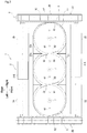
- FIGS. 1 to 4 illustrate an underwater cleaning machine 1 according to an embodiment.
- the underwater cleaning machine 1 cleans an object to be cleaned while moving along the surface of the object to be cleaned (for example, a hull, a farmed fish net, etc.) residing in the water.
- the underwater cleaning machine 1 includes a work machine body 2, a traveling device 3, propulsive-force generating propellers 4, a cleaning nozzle unit 5 (corresponding to a cleaning device), and a suction device 6.
- the work machine body 2 includes a propeller-side body 2A in which the propulsive-force generating propellers 4 are disposed, a nozzle-side body 2B in which the cleaning nozzle unit 5 is disposed, and a coupling body 2C that couples the propeller-side body 2A and the nozzle-side body 2B.
- the coupling body 2C is composed of a plurality of pipes extending in the vertical direction.
- the propeller-side body 2A includes a plurality of (three in this embodiment) tubular ducts 20A, 20B, and 20C having openings 21.
- the ducts 20A, 20B, and 20C are disposed in the left-right direction of the work machine body 2, and the propulsive-force generating propellers 4 are housed inside the respective openings 21.
- a traveling device 3 is disposed on the nozzle-side body 2B.
- the traveling device 3 includes motor cases 31A and 31B that house underwater motors M1 and M2, respectively, four wheels 32, 33, 34, 35 in the front, rear, left and right, and a pair of left and right crawler devices 36, 37.
- the underwater motor M1 housed in the front motor case 31A rotationally drives the right front wheel 33.
- the underwater motor M2 housed in the front motor case 31B rotationally drives the left rear wheel 34.
- the underwater motors M1 and M2 are composed of DC motors.
- a left crawler device 36 includes a drive wheel 36a, a first driven wheel 36b, a second driven wheel 36c, and an annular crawler 36d.
- the drive wheel 36a is fixed to the rotary shaft of the left rear wheel 34 and rotationally driven by the underwater motor M2.
- the first driven wheel 36b is fixed to the rotary shaft of the left front wheel 32.
- the second driven wheel 36c is rotatably supported above the drive wheel 36a and the first driven wheel 36b, between the drive wheel 36a and the first driven wheel 36b.
- the annular crawler 36d is wound around the drive wheel 36a, the first driven wheel 36b, and the second driven wheel 36c.
- the left front wheel 32 also rotates. That is, the underwater motor M2 simultaneously rotates the left rear wheel 34, the left front wheel 32, and the left crawler device 36 in the same direction.
- a right crawler device 37 includes a drive wheel 37a, a first driven wheel 37b, a second driven wheel 37c, and an annular crawler 37d.
- the drive wheel 37a is fixed to the rotary shaft of the right front wheel 33 and rotationally driven by the underwater motor M1.
- the first driven wheel 37b is fixed to the rotary shaft of the right rear wheel 35.
- the second driven wheel 37c is rotatably supported above the drive wheel 37a and the first driven wheel 37b, between the drive wheel 37a and the first driven wheel 37b.
- the annular crawler 37d is wound around the drive wheel 37a, the first driven wheel 37b, and the second driven wheel 37c.
- the right rear wheel 35 also rotates. That is, the underwater motor M1 simultaneously rotates the right front wheel 33, the right rear wheel 35, and the right crawler device 37 in the same direction.
- a power supply cable (not illustrated) is connected to each of the underwater motors M1 and M2, and power is supplied to each of the underwater motors M1 and M2 from a power supply device on board or on land through the power supply cable.
- the cleaning nozzle unit 5 ejects high-pressure water supplied from a high-pressure hose (not illustrated) toward the object to be cleaned, and cleans the object to be cleaned by a jet stream.
- the cleaning nozzle unit 5 is fixed to the lower portions of rotary shafts 7 rotatably supported by the nozzle-side body 2B.
- Rotary joints 71 are disposed in the middle portions of the rotary shafts 7.
- the rotary joints 71 are for transporting high-pressure water to the rotating cleaning nozzle unit 5. Since the rotary joints 71 each have substantially the same configuration as that of a rotary joint 624 described below, detailed description thereof will be omitted.
- the rotary joints 71 are supplied with high-pressure water pumped from a high-pressure water pump (not illustrated) on board or on land through a high-pressure hose.
- the high-pressure hose is connected to a branch joint 81, and the high-pressure water branched by the branch joint 81 is supplied to the respective rotary joints 71 via connection hoses 82, 83, and 84 extending from the branch joint 81.
- the high-pressure water supplied to the rotary joints 71 is supplied to the cleaning nozzle unit 5 through flow paths inside the rotary shafts 7.
- the cleaning nozzle unit 5 includes discoid cleaning bodies 51 fixed to the lower ends of the rotary shafts 7, and multiple cleaning nozzles 52 respectively disposed on the outer peripheral portion of the cleaning bodies 51.
- the cleaning bodies 51 are each composed of, for example, stainless steel, and can rotate and come into contact with shellfish or the like attached to the object to be cleaned to remove the shellfish or the like.
- a diffusion prevention cover 53 is disposed on the outer peripheral sides of the cleaning bodies 51 so as to protrude from the lower surface of the nozzle-side body 2B. By providing the diffusion prevention cover 53, the diffusion of dirty water can be prevented during cleaning.
- the diffusion prevention cover 53 includes a first cover portion 53a that surrounds the front and back of the three cleaning bodies 51, and a second cover portion 53b that is disposed along the outer peripheries of the respective cleaning bodies 51 between the adjacent cleaning bodies 51.
- a rubber packing (not illustrated) is disposed at the tip of the first cover portion 53a.
- the wheels 32, 33, 34, and 35 and the crawler devices 36 and 37 that come into contact with the surface of the object to be cleaned are arranged on the outer periphery of the nozzle-side body 2B, the diffusion of dirty water during cleaning can be further prevented.
- the two cleaning nozzles 52 are arranged so as to face each other across the axial center of each of the cleaning bodies 51.
- the cleaning nozzles 52 eject high-pressure water pumped from the high-pressure water pump.
- Each cleaning nozzle 52 tilts downward by a predetermined angle so that the ejection direction of the high-pressure water faces the object to be cleaned (see FIG. 2 ).
- the cleaning nozzle unit 5 rotates together with the rotary shafts 7 by the reaction force of the ejection generated by the high-pressure water being sprayed onto the surface of the object to be cleaned.
- the propulsive-force generating propellers 4 are fixed to the upper end of the rotary shafts 7. Therefore, when high-pressure water is ejected from the cleaning nozzles 52 and the rotary shaft 7 rotates together with the cleaning nozzle unit 5 by the ejection reaction force, the propulsive-force generating propellers 4 also rotate integrally.
- the rotation of the propulsive-force generating propellers 4 causes water between the propeller-side body 2A and the nozzle-side body 2B to be introduced into the ducts 20A, 20B, and 20C, and a water flow ejected from the openings 21 to be generated.
- This provides a propulsive force for the underwater cleaning machine 1, and thereby the underwater cleaning machine 1 is pressed against the object to be cleaned. Therefore, the wheels 32, 33, 34, and 35 and the crawler devices 36 and 37 do not float from the object to be cleaned, and the underwater cleaning machine 1 can clean the object to be cleaned while stably running along the surface of the object to be cleaned.
- the suction device 6 suctions dirty water (residual water) after cleaning by the cleaning nozzle unit 5.
- the suction device 6 includes water suction ports 61 for suctioning dirty water and a suction pump 62 for suctioning dirty water.
- the water suction ports 61 are formed on the lower surface of the nozzle-side body 2B.
- the water suction ports 61 are disposed on the inner side of the cleaning bodies 51, that is, above the cleaning bodies 51.
- two water suction ports 61 are provided for each cleaning body 51, and the two water suction ports 61 are arranged so as to face each other across the axial center of the rotary shaft 7.
- the dirty water after the cleaning by the cleaning nozzle unit 5 is suctioned from the water suction ports 61 through the voids on the outer peripheral sides and the inner sides of the cleaning bodies 51 as indicated by the dashed-dotted line in FIG. 4 .
- the diffusion prevention cover 53 disposed around the cleaning bodies 51 causes the dirty water to be effectively suctioned from the water suction ports 61.
- FIG. 5 is a side view of the suction pump 62.
- the vertical direction in FIG. 5 is referred to as the vertical direction of the suction pump 62.
- the suction pump 62 includes a hollow cylindrical casing 621, an impeller 622 disposed inside the casing 621, and a plurality of suction ports 623 formed in the casing 621.
- a lower bearing 621c is fixed to the upper end surface 621a of the casing 621.
- a suction portion 621d projecting in a columnar shape is formed on the lower end surface (bottom surface) 621b of the casing 621, and the suction ports 623 are arranged on the outer peripheral portion of the suction portion 621d.
- six suction ports 623 are arranged at equal intervals along the circumferential direction of the suction portion 621d.
- Each suction port 623 opens toward a tangential direction of the casing 621, specifically, in the tangential direction of the suction portion 621d (see FIG. 4 ).
- Each suction port 623 is connected to the corresponding water suction port 61 by a suction hose (not illustrated) (see FIG. 4 ). In this way, the dirty water suctioned from the water suction ports 61 is suctioned into the casing 621 through the suction hose and the suction ports 623.
- a discharge portion 621e for discharging the suctioned dirty water is disposed on the outer peripheral portion of the casing 621.
- a dirty water transfer hose (not illustrated) is connected to the end of the discharge portion 621e, and the dirty water discharged from the suction pump 62 is transferred to the ship or land through the dirty water transfer hose.
- a middle case cover 621f is fixed to the upper end surface 621a of the casing 621, and an upper case cover 621g is fixed to the upper surface of the middle cover 621f.
- the middle case cover 621f covers the lower bearing 621c.
- a rotary joint 624 which will be described below, is housed inside the upper case cover 621g.
- An upper bearing 621h is fixed on the upper surface of the upper case cover 621g.
- the impeller 622 includes a discoid impeller body 622a, a plurality of ejection nozzles 622b disposed on the outer peripheral portion of the impeller body 622a, a plurality of blade portions 622c disposed on the lower surface of the impeller body 622a, and a rotary shaft 622d fixed to the upper surface of the impeller body 622a.
- a pair of ejection nozzles 622b are disposed across the rotary shaft of the impeller 622.
- the two ejection nozzles 622b are arranged so as to face each other across the axial center of the impeller body 622a.
- the ejection nozzles 622b eject high-pressure water pumped from the high-pressure water pump (not illustrated) described above.
- Each ejection nozzle 622b is disposed so that the ejection direction of the high-pressure water faces the tangential direction of the impeller body 622a. Therefore, when high-pressure water is ejected from the ejection nozzles 622b, the impeller body 622a rotates by the reaction force of the ejection of the high-pressure water. That is, the impeller 622 is driven by the reaction force of the ejection of high-pressure water from the ejection nozzles 622b.
- the blade portions 622c rotate together with the impeller body 622a to apply a centrifugal force to the liquid in the casing 621.
- six blade portions 622c are arranged at equal intervals along the circumferential direction of the impeller body 622a.
- the lower end of the rotary shaft 622d is fixed to the impeller body 622a.
- the rotary shaft 622d is rotatably supported by the lower bearing 621c and the upper bearing 621h.
- a flow path 622e for transporting high-pressure water in the axial direction is formed on the rotary shaft 622d.
- the upper end of the flow path 622e is positioned at the central area of the rotary shaft 622d.
- the lower end of the flow path 622e extends to the impeller body 622a and communicates with the ejection nozzles 622b via connection pipes 622f.
- the rotary joint 624 is for transporting high-pressure water to the rotating impeller 622.
- the rotary joint 624 includes the rotary shaft 622d of the impeller 622 and a fixed housing 624a surrounding the rotary shaft 622d.
- a receiving hole 624b that communicates with the flow path 622e is formed in the rotary shaft 622d.
- a supply hole 624c is formed in the fixed housing 624a at a height corresponding to the receiving hole 624b.
- the fixed housing 624a is fixed to the upper surface of the middle case cover 621f.
- a crank joint 625 is connected to the supply hole 624c in the fixed housing 624a.
- a connecting hose 85 (see FIG. 1 ) extending from the branch joint 81 is connected to the crank joint 625.
- high-pressure water pumped from a high-pressure water pump (not illustrated) on board or on land is supplied to the rotary joint 624 through the high-pressure hose, the branch joint 81, the connecting hose 85, and the crank joint 625.
- the high-pressure water supplied to the rotary joint 624 is supplied to the ejection nozzles 622b through the flow path 622e of the rotary shaft 622d and the connection pipe 622f, and is ejected from the ejection nozzles 622b.
- the impeller 622 is rotationally driven by the reaction force of the ejection of high-pressure water from the ejection nozzles 622b. Since a centrifugal force is applied to the liquid inside the casing 621 by the rotation of the impeller 622, the suction pump 62 discharges the dirty water from the discharge portion 621e and suctions dirty water from the suction ports 623. That is, since the suction pump 62 is driven by the high-pressure water supplied from an external high-pressure water pump, it is not necessary to mount a drive device such as a motor for driving the suction device 6 on the machine body.
- the underwater cleaning machine 1 of the present embodiment is an underwater cleaning machine 1 that cleans an object to be cleaned while moving along the surface of the object to be cleaned residing underwater, and includes a cleaning nozzle unit 5 that cleans the object to be cleaned by ejecting high-pressure water toward the object to be cleaned, a suction device 6 that suctions dirty water after cleaning by the cleaning nozzle unit 5.
- the cleaning nozzle unit 5 and the suction device 6 are driven by high-pressure water supplied from an external high-pressure water pump.
- the suction device 6 for suctioning the dirty water after cleaning by the cleaning nozzle unit 5 since the suction device 6 for suctioning the dirty water after cleaning by the cleaning nozzle unit 5 is provided, contamination of seawater can be reliably prevented. Since the cleaning nozzle unit 5 and the suction device 6 are driven by the high-pressure water supplied from the external high-pressure water pump, multiple drive devices for driving the cleaning nozzle unit 5 and the suction device 6 need not to be mounted on the machine body, and thus the work equipment is lightweight.
- the high-pressure water pumped from the high-pressure water pump through one high-pressure hose is distributed between the cleaning nozzle unit 5 and the suction device 6.
- the cleaning nozzle unit 5 and the suction device 6 may be supplied with high-pressure water pumped from a plurality of high-pressure water pumps through high-pressure hoses.
- the cleaning nozzle unit 5 includes the discoid cleaning bodies 51 that rotate by the reaction force of ejection of high-pressure water on the object to be cleaned; the suction device 6 has the water suction ports 61 on the inner side of the cleaning bodies 51; and dirty water is suctioned from the water suction ports 61 through the voids on the outer peripheral side and the inner side of the cleaning bodies 51.
- the diffusion prevention cover 53 for preventing the diffusion of dirty water disposed on the outer peripheral sides of the cleaning bodies 51.
- the suction device 6 includes the suction pump 62 for suctioning dirty water; the suction pump 62 includes the hollow cylindrical casing 621, the impeller 622 disposed inside the casing 621, and the plurality of suction ports 623 formed in the casing 621; and the impeller 622 is driven by the reaction force of the ejection of high-pressure water from the ejection nozzles 622b disposed on the impeller 622.
- the plurality of suction ports 623 are disposed on the bottom surface of the casing 621 along the circumferential direction, and the suction ports 623 are opened toward a tangential direction of the casing 621.
- the ejection nozzles 622b are disposed across the rotary shaft 622d of the impeller 622.
Landscapes
- Chemical & Material Sciences (AREA)
- Engineering & Computer Science (AREA)
- Combustion & Propulsion (AREA)
- Mechanical Engineering (AREA)
- Ocean & Marine Engineering (AREA)
- Cleaning By Liquid Or Steam (AREA)
- Structures Of Non-Positive Displacement Pumps (AREA)
Applications Claiming Priority (2)
| Application Number | Priority Date | Filing Date | Title |
|---|---|---|---|
| JP2019006933A JP7049279B2 (ja) | 2019-01-18 | 2019-01-18 | 水中清掃作業機 |
| PCT/JP2020/000284 WO2020149190A1 (fr) | 2019-01-18 | 2020-01-08 | Machine de nettoyage sous-marine |
Publications (3)
| Publication Number | Publication Date |
|---|---|
| EP3912738A1 true EP3912738A1 (fr) | 2021-11-24 |
| EP3912738A4 EP3912738A4 (fr) | 2022-10-12 |
| EP3912738B1 EP3912738B1 (fr) | 2025-05-14 |
Family
ID=71613881
Family Applications (1)
| Application Number | Title | Priority Date | Filing Date |
|---|---|---|---|
| EP20741370.9A Active EP3912738B1 (fr) | 2019-01-18 | 2020-01-08 | Machine de nettoyage sous-marine |
Country Status (5)
| Country | Link |
|---|---|
| EP (1) | EP3912738B1 (fr) |
| JP (1) | JP7049279B2 (fr) |
| CN (1) | CN113272077A (fr) |
| SG (1) | SG11202103932PA (fr) |
| WO (1) | WO2020149190A1 (fr) |
Families Citing this family (3)
| Publication number | Priority date | Publication date | Assignee | Title |
|---|---|---|---|---|
| JP2024136515A (ja) | 2023-03-24 | 2024-10-04 | ヤンマーホールディングス株式会社 | 水中洗浄作業装置 |
| JP2024136516A (ja) | 2023-03-24 | 2024-10-04 | ヤンマーホールディングス株式会社 | 水中洗浄作業装置 |
| JP2024136518A (ja) | 2023-03-24 | 2024-10-04 | ヤンマーホールディングス株式会社 | 水中洗浄作業装置 |
Family Cites Families (9)
| Publication number | Priority date | Publication date | Assignee | Title |
|---|---|---|---|---|
| GB1092133A (en) * | 1965-03-04 | 1967-11-22 | Exxon Research Engineering Co | Apparatus for manoeuvring on a submerged surface |
| JPS5459764U (fr) * | 1977-10-05 | 1979-04-25 | ||
| DE4039092C1 (fr) * | 1990-12-07 | 1992-04-16 | Deutsche Lufthansa Ag, 5000 Koeln, De | |
| US5970574A (en) * | 1997-04-24 | 1999-10-26 | Hydrochem Industrial Services, Inc. | Apparatus and method for cleaning surfaces by removing and containing waste |
| JP3592204B2 (ja) | 2000-01-26 | 2004-11-24 | ヤンマー株式会社 | 水中清掃ロボット |
| NO20083079L (no) * | 2008-07-11 | 2010-01-12 | Mpi Trond Sivertsen | Renseapparat for fjerning av marin begroning og anvendelse av apparat. |
| JP5823272B2 (ja) * | 2011-12-02 | 2015-11-25 | 株式会社奥村組 | ウォータージェット治具 |
| US9038557B2 (en) * | 2012-09-14 | 2015-05-26 | Raytheon Company | Hull robot with hull separation countermeasures |
| CN208288519U (zh) * | 2018-04-16 | 2018-12-28 | 宁德新能源科技有限公司 | 对物料除尘的装置 |
-
2019
- 2019-01-18 JP JP2019006933A patent/JP7049279B2/ja active Active
-
2020
- 2020-01-08 WO PCT/JP2020/000284 patent/WO2020149190A1/fr not_active Ceased
- 2020-01-08 CN CN202080007720.4A patent/CN113272077A/zh active Pending
- 2020-01-08 EP EP20741370.9A patent/EP3912738B1/fr active Active
- 2020-01-08 SG SG11202103932PA patent/SG11202103932PA/en unknown
Also Published As
| Publication number | Publication date |
|---|---|
| WO2020149190A1 (fr) | 2020-07-23 |
| EP3912738A4 (fr) | 2022-10-12 |
| EP3912738B1 (fr) | 2025-05-14 |
| JP2020116478A (ja) | 2020-08-06 |
| CN113272077A (zh) | 2021-08-17 |
| SG11202103932PA (en) | 2021-05-28 |
| JP7049279B2 (ja) | 2022-04-06 |
Similar Documents
| Publication | Publication Date | Title |
|---|---|---|
| EP3912738B1 (fr) | Machine de nettoyage sous-marine | |
| JP3592204B2 (ja) | 水中清掃ロボット | |
| AU2006340223C1 (en) | Submersible cleaning robot | |
| US9308977B2 (en) | Surface-cleaning device and vehicle | |
| US10494829B2 (en) | Device for cleaning a submerged surface with a propelled water jet | |
| CN109080788B (zh) | 用于清洁淹没表面的清洁头和方法 | |
| WO2018199767A1 (fr) | Dispositif et appareil de nettoyage sous-marins | |
| KR20140092108A (ko) | 선박의 프로펠러용 크리닝 장치 | |
| US8177917B2 (en) | Cleaning assembly | |
| JPH11169807A (ja) | 管内清掃装置および管内清掃方法 | |
| KR20090011119U (ko) | 더덕, 우엉 및 도라지 박피기 | |
| US7552505B2 (en) | Cleaning system for cleaning the outer skin of aircraft | |
| JP2552901B2 (ja) | 高圧水等噴射装置及び該装置に用いる集水カバー | |
| KR20240073351A (ko) | 모어 청소 장치 | |
| JP2007244940A (ja) | 水中清掃ロボット | |
| KR102322287B1 (ko) | 프로펠러 이물질 고착 방지장치 및 이를 가지는 선박 | |
| US20220001410A1 (en) | Device comprising rotary nozzle | |
| JPH0387130A (ja) | 網清掃装置 | |
| KR20110132701A (ko) | 일체형 수중추진장치 | |
| HK40002031B (en) | A surface cleaning device | |
| HK40002031A (en) | A surface cleaning device | |
| HK40002537B (en) | Cleaning head and method for cleaning a submerged surface | |
| HK40002537A (en) | Cleaning head and method for cleaning a submerged surface | |
| HK1189856B (en) | A surface-cleaning device and vehicle |
Legal Events
| Date | Code | Title | Description |
|---|---|---|---|
| STAA | Information on the status of an ep patent application or granted ep patent |
Free format text: STATUS: THE INTERNATIONAL PUBLICATION HAS BEEN MADE |
|
| PUAI | Public reference made under article 153(3) epc to a published international application that has entered the european phase |
Free format text: ORIGINAL CODE: 0009012 |
|
| STAA | Information on the status of an ep patent application or granted ep patent |
Free format text: STATUS: REQUEST FOR EXAMINATION WAS MADE |
|
| 17P | Request for examination filed |
Effective date: 20210809 |
|
| AK | Designated contracting states |
Kind code of ref document: A1 Designated state(s): AL AT BE BG CH CY CZ DE DK EE ES FI FR GB GR HR HU IE IS IT LI LT LU LV MC MK MT NL NO PL PT RO RS SE SI SK SM TR |
|
| DAV | Request for validation of the european patent (deleted) | ||
| DAX | Request for extension of the european patent (deleted) | ||
| A4 | Supplementary search report drawn up and despatched |
Effective date: 20220909 |
|
| RIC1 | Information provided on ipc code assigned before grant |
Ipc: B63B 59/10 20060101ALI20220905BHEP Ipc: B08B 3/02 20060101AFI20220905BHEP |
|
| STAA | Information on the status of an ep patent application or granted ep patent |
Free format text: STATUS: EXAMINATION IS IN PROGRESS |
|
| 17Q | First examination report despatched |
Effective date: 20231017 |
|
| GRAP | Despatch of communication of intention to grant a patent |
Free format text: ORIGINAL CODE: EPIDOSNIGR1 |
|
| STAA | Information on the status of an ep patent application or granted ep patent |
Free format text: STATUS: GRANT OF PATENT IS INTENDED |
|
| INTG | Intention to grant announced |
Effective date: 20241206 |
|
| GRAS | Grant fee paid |
Free format text: ORIGINAL CODE: EPIDOSNIGR3 |
|
| GRAA | (expected) grant |
Free format text: ORIGINAL CODE: 0009210 |
|
| STAA | Information on the status of an ep patent application or granted ep patent |
Free format text: STATUS: THE PATENT HAS BEEN GRANTED |
|
| AK | Designated contracting states |
Kind code of ref document: B1 Designated state(s): AL AT BE BG CH CY CZ DE DK EE ES FI FR GB GR HR HU IE IS IT LI LT LU LV MC MK MT NL NO PL PT RO RS SE SI SK SM TR |
|
| REG | Reference to a national code |
Ref country code: GB Ref legal event code: FG4D |
|
| REG | Reference to a national code |
Ref country code: CH Ref legal event code: EP |
|
| REG | Reference to a national code |
Ref country code: IE Ref legal event code: FG4D |
|
| REG | Reference to a national code |
Ref country code: DE Ref legal event code: R096 Ref document number: 602020051266 Country of ref document: DE |
|
| REG | Reference to a national code |
Ref country code: NL Ref legal event code: FP |
|
| PG25 | Lapsed in a contracting state [announced via postgrant information from national office to epo] |
Ref country code: PT Free format text: LAPSE BECAUSE OF FAILURE TO SUBMIT A TRANSLATION OF THE DESCRIPTION OR TO PAY THE FEE WITHIN THE PRESCRIBED TIME-LIMIT Effective date: 20250915 Ref country code: ES Free format text: LAPSE BECAUSE OF FAILURE TO SUBMIT A TRANSLATION OF THE DESCRIPTION OR TO PAY THE FEE WITHIN THE PRESCRIBED TIME-LIMIT Effective date: 20250514 Ref country code: FI Free format text: LAPSE BECAUSE OF FAILURE TO SUBMIT A TRANSLATION OF THE DESCRIPTION OR TO PAY THE FEE WITHIN THE PRESCRIBED TIME-LIMIT Effective date: 20250514 |
|
| REG | Reference to a national code |
Ref country code: LT Ref legal event code: MG9D |
|
| PG25 | Lapsed in a contracting state [announced via postgrant information from national office to epo] |
Ref country code: NO Free format text: LAPSE BECAUSE OF FAILURE TO SUBMIT A TRANSLATION OF THE DESCRIPTION OR TO PAY THE FEE WITHIN THE PRESCRIBED TIME-LIMIT Effective date: 20250814 Ref country code: GR Free format text: LAPSE BECAUSE OF FAILURE TO SUBMIT A TRANSLATION OF THE DESCRIPTION OR TO PAY THE FEE WITHIN THE PRESCRIBED TIME-LIMIT Effective date: 20250815 |
|
| PG25 | Lapsed in a contracting state [announced via postgrant information from national office to epo] |
Ref country code: PL Free format text: LAPSE BECAUSE OF FAILURE TO SUBMIT A TRANSLATION OF THE DESCRIPTION OR TO PAY THE FEE WITHIN THE PRESCRIBED TIME-LIMIT Effective date: 20250514 |
|
| REG | Reference to a national code |
Ref country code: AT Ref legal event code: MK05 Ref document number: 1794391 Country of ref document: AT Kind code of ref document: T Effective date: 20250514 |
|
| PG25 | Lapsed in a contracting state [announced via postgrant information from national office to epo] |
Ref country code: BG Free format text: LAPSE BECAUSE OF FAILURE TO SUBMIT A TRANSLATION OF THE DESCRIPTION OR TO PAY THE FEE WITHIN THE PRESCRIBED TIME-LIMIT Effective date: 20250514 |
|
| PG25 | Lapsed in a contracting state [announced via postgrant information from national office to epo] |
Ref country code: HR Free format text: LAPSE BECAUSE OF FAILURE TO SUBMIT A TRANSLATION OF THE DESCRIPTION OR TO PAY THE FEE WITHIN THE PRESCRIBED TIME-LIMIT Effective date: 20250514 |
|
| PG25 | Lapsed in a contracting state [announced via postgrant information from national office to epo] |
Ref country code: AT Free format text: LAPSE BECAUSE OF FAILURE TO SUBMIT A TRANSLATION OF THE DESCRIPTION OR TO PAY THE FEE WITHIN THE PRESCRIBED TIME-LIMIT Effective date: 20250514 |
|
| PG25 | Lapsed in a contracting state [announced via postgrant information from national office to epo] |
Ref country code: RS Free format text: LAPSE BECAUSE OF FAILURE TO SUBMIT A TRANSLATION OF THE DESCRIPTION OR TO PAY THE FEE WITHIN THE PRESCRIBED TIME-LIMIT Effective date: 20250814 |
|
| PG25 | Lapsed in a contracting state [announced via postgrant information from national office to epo] |
Ref country code: IS Free format text: LAPSE BECAUSE OF FAILURE TO SUBMIT A TRANSLATION OF THE DESCRIPTION OR TO PAY THE FEE WITHIN THE PRESCRIBED TIME-LIMIT Effective date: 20250914 |
|
| PG25 | Lapsed in a contracting state [announced via postgrant information from national office to epo] |
Ref country code: LV Free format text: LAPSE BECAUSE OF FAILURE TO SUBMIT A TRANSLATION OF THE DESCRIPTION OR TO PAY THE FEE WITHIN THE PRESCRIBED TIME-LIMIT Effective date: 20250514 |
|
| PG25 | Lapsed in a contracting state [announced via postgrant information from national office to epo] |
Ref country code: DK Free format text: LAPSE BECAUSE OF FAILURE TO SUBMIT A TRANSLATION OF THE DESCRIPTION OR TO PAY THE FEE WITHIN THE PRESCRIBED TIME-LIMIT Effective date: 20250514 Ref country code: SM Free format text: LAPSE BECAUSE OF FAILURE TO SUBMIT A TRANSLATION OF THE DESCRIPTION OR TO PAY THE FEE WITHIN THE PRESCRIBED TIME-LIMIT Effective date: 20250514 |
|
| PG25 | Lapsed in a contracting state [announced via postgrant information from national office to epo] |
Ref country code: CZ Free format text: LAPSE BECAUSE OF FAILURE TO SUBMIT A TRANSLATION OF THE DESCRIPTION OR TO PAY THE FEE WITHIN THE PRESCRIBED TIME-LIMIT Effective date: 20250514 |
|
| PG25 | Lapsed in a contracting state [announced via postgrant information from national office to epo] |
Ref country code: EE Free format text: LAPSE BECAUSE OF FAILURE TO SUBMIT A TRANSLATION OF THE DESCRIPTION OR TO PAY THE FEE WITHIN THE PRESCRIBED TIME-LIMIT Effective date: 20250514 |
|
| PG25 | Lapsed in a contracting state [announced via postgrant information from national office to epo] |
Ref country code: RO Free format text: LAPSE BECAUSE OF FAILURE TO SUBMIT A TRANSLATION OF THE DESCRIPTION OR TO PAY THE FEE WITHIN THE PRESCRIBED TIME-LIMIT Effective date: 20250514 Ref country code: SK Free format text: LAPSE BECAUSE OF FAILURE TO SUBMIT A TRANSLATION OF THE DESCRIPTION OR TO PAY THE FEE WITHIN THE PRESCRIBED TIME-LIMIT Effective date: 20250514 |
|
| PG25 | Lapsed in a contracting state [announced via postgrant information from national office to epo] |
Ref country code: IT Free format text: LAPSE BECAUSE OF FAILURE TO SUBMIT A TRANSLATION OF THE DESCRIPTION OR TO PAY THE FEE WITHIN THE PRESCRIBED TIME-LIMIT Effective date: 20250514 |
|
| REG | Reference to a national code |
Ref country code: DE Ref legal event code: R097 Ref document number: 602020051266 Country of ref document: DE |
|
| PLBE | No opposition filed within time limit |
Free format text: ORIGINAL CODE: 0009261 |
|
| STAA | Information on the status of an ep patent application or granted ep patent |
Free format text: STATUS: NO OPPOSITION FILED WITHIN TIME LIMIT |
|
| REG | Reference to a national code |
Ref country code: CH Ref legal event code: L10 Free format text: ST27 STATUS EVENT CODE: U-0-0-L10-L00 (AS PROVIDED BY THE NATIONAL OFFICE) Effective date: 20260325 |
|
| 26N | No opposition filed |
Effective date: 20260217 |