EP3912841A1 - Ventilateur de toit pour véhicules de loisirs - Google Patents
Ventilateur de toit pour véhicules de loisirs Download PDFInfo
- Publication number
- EP3912841A1 EP3912841A1 EP21174549.2A EP21174549A EP3912841A1 EP 3912841 A1 EP3912841 A1 EP 3912841A1 EP 21174549 A EP21174549 A EP 21174549A EP 3912841 A1 EP3912841 A1 EP 3912841A1
- Authority
- EP
- European Patent Office
- Prior art keywords
- mounting frame
- cover
- scissor
- roof
- point
- Prior art date
- Legal status (The legal status is an assumption and is not a legal conclusion. Google has not performed a legal analysis and makes no representation as to the accuracy of the status listed.)
- Withdrawn
Links
Images


Classifications
-
- B—PERFORMING OPERATIONS; TRANSPORTING
- B60—VEHICLES IN GENERAL
- B60J—WINDOWS, WINDSCREENS, NON-FIXED ROOFS, DOORS, OR SIMILAR DEVICES FOR VEHICLES; REMOVABLE EXTERNAL PROTECTIVE COVERINGS SPECIALLY ADAPTED FOR VEHICLES
- B60J7/00—Non-fixed roofs; Roofs with movable panels, e.g. rotary sunroofs
- B60J7/08—Non-fixed roofs; Roofs with movable panels, e.g. rotary sunroofs of non-sliding type, i.e. movable or removable roofs or panels, e.g. let-down tops or roofs capable of being easily detached or of assuming a collapsed or inoperative position
- B60J7/16—Non-fixed roofs; Roofs with movable panels, e.g. rotary sunroofs of non-sliding type, i.e. movable or removable roofs or panels, e.g. let-down tops or roofs capable of being easily detached or of assuming a collapsed or inoperative position non-foldable and rigid, e.g. a one-piece hard-top or a single rigid roof panel
- B60J7/1628—Non-fixed roofs; Roofs with movable panels, e.g. rotary sunroofs of non-sliding type, i.e. movable or removable roofs or panels, e.g. let-down tops or roofs capable of being easily detached or of assuming a collapsed or inoperative position non-foldable and rigid, e.g. a one-piece hard-top or a single rigid roof panel for covering the passenger compartment
- B60J7/1635—Non-fixed roofs; Roofs with movable panels, e.g. rotary sunroofs of non-sliding type, i.e. movable or removable roofs or panels, e.g. let-down tops or roofs capable of being easily detached or of assuming a collapsed or inoperative position non-foldable and rigid, e.g. a one-piece hard-top or a single rigid roof panel for covering the passenger compartment of non-convertible vehicles
- B60J7/1642—Roof panels, e.g. sunroofs or hatches, movable relative to the main roof structure, e.g. by lifting or pivoting
-
- E—FIXED CONSTRUCTIONS
- E05—LOCKS; KEYS; WINDOW OR DOOR FITTINGS; SAFES
- E05D—HINGES OR SUSPENSION DEVICES FOR DOORS, WINDOWS OR WINGS
- E05D15/00—Suspension arrangements for wings
- E05D15/40—Suspension arrangements for wings supported on arms movable in vertical planes
- E05D15/42—Suspension arrangements for wings supported on arms movable in vertical planes with pivoted arms and horizontally-sliding guides
-
- E—FIXED CONSTRUCTIONS
- E05—LOCKS; KEYS; WINDOW OR DOOR FITTINGS; SAFES
- E05D—HINGES OR SUSPENSION DEVICES FOR DOORS, WINDOWS OR WINGS
- E05D15/00—Suspension arrangements for wings
- E05D15/40—Suspension arrangements for wings supported on arms movable in vertical planes
- E05D15/46—Suspension arrangements for wings supported on arms movable in vertical planes with two pairs of pivoted arms
-
- E—FIXED CONSTRUCTIONS
- E05—LOCKS; KEYS; WINDOW OR DOOR FITTINGS; SAFES
- E05D—HINGES OR SUSPENSION DEVICES FOR DOORS, WINDOWS OR WINGS
- E05D15/00—Suspension arrangements for wings
- E05D15/48—Suspension arrangements for wings allowing alternative movements
-
- E—FIXED CONSTRUCTIONS
- E05—LOCKS; KEYS; WINDOW OR DOOR FITTINGS; SAFES
- E05D—HINGES OR SUSPENSION DEVICES FOR DOORS, WINDOWS OR WINGS
- E05D15/00—Suspension arrangements for wings
- E05D15/48—Suspension arrangements for wings allowing alternative movements
- E05D2015/487—Tilting or swinging movements
-
- E—FIXED CONSTRUCTIONS
- E05—LOCKS; KEYS; WINDOW OR DOOR FITTINGS; SAFES
- E05Y—INDEXING SCHEME ASSOCIATED WITH SUBCLASSES E05D AND E05F, RELATING TO CONSTRUCTION ELEMENTS, ELECTRIC CONTROL, POWER SUPPLY, POWER SIGNAL OR TRANSMISSION, USER INTERFACES, MOUNTING OR COUPLING, DETAILS, ACCESSORIES, AUXILIARY OPERATIONS NOT OTHERWISE PROVIDED FOR, APPLICATION THEREOF
- E05Y2900/00—Application of doors, windows, wings or fittings thereof
- E05Y2900/50—Application of doors, windows, wings or fittings thereof for vehicles
- E05Y2900/512—Application of doors, windows, wings or fittings thereof for vehicles for recreational vehicles
Definitions
- the invention relates to a roof vent for a leisure vehicle, in particular for a mobile home or a caravan, according to the preamble of claim 1.
- roof ventilators uses a mechanical erection mechanism that is not integrated into the assembly unit. Such roof ventilators are used quite generally in recreational vehicles.
- the term recreational vehicles is a generic term that encompasses both caravans and motorhomes.
- the term recreational vehicles also includes mobile homes that are integrated into standard box vans or small vans without a special body structure and, in particular, vehicles that, in addition to being used for camping, are provided with flexible or at least partially removable interior fittings and can also be used for other purposes.
- Stand-up mechanisms used in the prior art only raise a cover hood of such a roof ventilator in the vertical direction, that is to say only lift it up.
- a mechanically adjustable caravan roof hatch is known with mutually symmetrical lever scissors, a first lever of the lever scissors is rotatably attached to a fixed point of a mounting frame and its other end is guided in a longitudinal slot of a hood of the caravan roof hatch.
- a second lever which is rotatably attached to a fixed point of the hood and can be moved in the mounting frame in a linear guide by a rack to raise the hood, it is possible to raise the hood.
- the disadvantage of this prior art is that the resulting ventilation opening through the parallel lifting is limited in its cross-section.
- the present invention is based on the object of providing a roof ventilator for a recreational vehicle which improves the prior art described above, and in particular a reliable and safe electrical actuation should also be possible.
- a mounting frame is provided in a mounting unit for insertion into a roof cutout and a cover hood that can be raised from a closed position on the mounting frame to an open position by two scissor levers , which connect the mounting frame and the cover, the scissor levers are connected in a pivot point and an end point of the scissors lever is pivoted rotatably in the cover at a fixed point and an end point of the scissor lever is rotatably applied in the mounting frame at a fixed point, each remaining end points in longitudinal guides are slidably guided in the cover and the mounting frame and the scissor lever guided in the longitudinal guide of the mounting frame can be shifted to lift the cover hood by an actuating mechanism, the length of a scissor lever section of both scissor levers on the same side of the pivot point is shorter than the length of the scissor lever sections on the other side of the pivot point, so that when the
- An advantageous and essential innovation of the invention is a lift-tilt function in the setup kinematics of the roof fan cover when it is opened, through which the roof fan cover is brought into a tilted position in the upper end position in the open state. Furthermore, the kinematics are now completely stowed in the component.
- I. E. There is a unit that can be assembled as a whole, and in which, in addition to the actual cover, the lever mechanism and an optional electric drive are integrated. This eliminates the need for multiple items can be installed, but a single component can be installed on the open roof cutout. The additional tilting of the cover hood of the roof ventilator and the resulting angle make a significantly larger opening possible, which in turn significantly improves the ventilation behavior and thus the comfort in the vehicle.
- the two end points of one or both scissor levers can advantageously each form an obtuse angle smaller than 180 ° with the pivot point, in particular the pivot point can be offset upwards in the closed position of the cover on the mounting frame.
- the arrangement can be such that in the closed state the pivot point is as high as possible on the cover and the mounting points of the scissor levers on the cover are almost or in a straight line with this pivot point.
- the lower scissor lever sections with their mounting points on the mounting frame have a more favorable angle to the pivot point if the actuating device is to lift the cover by sliding it in the longitudinal guide or if it is to pull it down into the locked position with a certain force. Due to the angle of the two lower bearing points with the pivot point, a greater vertical force can be achieved through a linear displacement.
- two scissor levers are arranged on one side of the mounting frame and the short ends of the scissor levers point in the direction of travel so that the cover tilts down in the direction of travel when it is lifted.
- the scissor lever not only makes it possible to lift the cover, but also to tilt it.
- This tilting is preferably carried out in such a way that in the upper raised position the lower side points in the direction of travel.
- the movement can be such that, forcibly, an increasing tilting takes place during the lifting. This also increases safety if driving inadvertently with the cover open, in particular driving very quickly.
- the cover is pressed shut and not burdened by the wind in the direction of a further opening.
- Each scissor lever is preferably displaceable at one end and rotatably mounted at a fixed point at the other end.
- a scissor lever it is also conceivable for a scissor lever to be mounted so as to be longitudinally displaceable both in the cover hood and in the mounting frame.
- each scissor lever is rotatably mounted in a fixed point at the end of its short scissor lever section.
- the actuation mechanism can consist of a rotatable threaded rod and an internally threaded section rotatably connected to the end of the scissor lever.
- This internally threaded section in the sense of a nut can for example be a nut element guided through the threaded rod and a surface of the mounting frame or other guide elements as well as solely through the threaded rod itself, to which the scissor lever is pivoted. By turning the threaded rod, the nut element is then displaced linearly.
- the actuation mechanism can be driven electrically, in particular drive a threaded rod as described above by an electric motor.
- opening movement can be driven electrically and the roof ventilator can be conveniently operated using an electrical switch.
- the cover has an edge protruding beyond a ventilation opening of the mounting frame and at least partially covering the mounting frame, in particular an edge that kinks down, and an electric drive of the actuating mechanism is arranged below this edge on the mounting frame.
- the cover hood When closed, the cover hood also covers the mounting frame and functional elements of the roof ventilator and thus protects them Weather effects.
- the cover itself can be made of a single piece of a transparent material, for example a plastic or plexiglass. This enables a simple structure with few parts that is inexpensive to manufacture.
- the electric drive can be arranged on a transverse side of the mounting frame and have a drive for the respective threaded rod on both longitudinal sides at the corner of the mounting frame.
- the parts of the electric drive can thus be arranged under the covering edge of the cover hood and can additionally be protected from the effects of the weather by this in the closed state or only slightly open state.
- lamellae for shading can be arranged and rotatably mounted, in particular in a longitudinal direction of the roof ventilator.
- This optional lamellar cassette in the interior allows variously adjustable lighting conditions.
- the incidence of daylight can be regulated by turning the slats. This can be done by an actuating mechanism or by hand, in which case, for example, the lamella pivot point can all be coupled so that all the lamellae rotate by turning by hand from one lamella.
- the Fig. 1 shows a roof ventilator 1 according to the prior art in a perspective view from above.
- a cover 2 made of a transparent material such as plexiglass, which is made in one piece, is the mounting frame 3 and the actual ventilation opening 4, on the upper edge of which sits a seal 5, which rests against this when the cover 2 is lowered.
- the Fig. 2 shows the roof fan 1 of Fig. 1 in perspective view from below.
- the mounting frame 3 has on its underside a cover 6 which is arranged towards the interior.
- the cover 2 can be raised by means of a hand crank 7 and an actuating mechanism not shown in detail here.
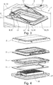
- the Fig. 3 shows a roof ventilator 1 according to the invention in a perspective view. Components that correspond to those described so far are denoted by the same reference numerals as in the following figures.
- the cover 2 is shown in the open position above the mounting frame 3, whereby it is not only raised but also tilted.
- a first scissors lever 8 is pivoted to the mounting frame 3 in a rotatable manner at a first fixed point 9.
- the opposite end point of the first scissors lever 8 is guided in a longitudinal guide 10, shown here in the parallel structure on the second side of the assembly frame 3, on the cover hood 2.
- a second scissor lever 11 is rotatably articulated to the cover 2 at a fixed point 12 and is guided on the mounting frame 3 in a longitudinal guide 14 formed by a threaded rod 13.
- the scissor lever 11 is attached to a nut element 16 at a pivot point 22 so as to be pivotable.
- An actuating mechanism 23 consists of an electric drive unit 15 can set the threaded rod 13 located there in rotation on both sides of the mounting frame 3, whereby the nut element 16 is displaced and the fastening point of the second scissor lever 11 is displaced.
- the first scissor lever 8 and the second scissor lever 11 are connected to one another at a pivot point 17.
- a short scissor lever section 18 of the first scissor lever 8 is arranged on the same side of the pivot point 17 as a short scissor lever section 19 of the second scissor lever 11 and shorter than the respective scissor lever sections on the other side of the pivot point.
- the Fig. 4 shows the roof fan of the Fig. 3 in an exploded view.
- the cover 2 is arranged above the mounting frame 3, with lamellas 20 being arranged in a holding frame 21 on the underside.
- the Fig. 5 shows a view from below of the slats 20 of a roof ventilator in the holding frame 21 in the installation situation.
- the incidence of daylight can be regulated by adjusting the angle.
- the Fig. 6 shows a further embodiment of a roof ventilator 1 in a perspective side view.
- the first scissor lever 8 and the second scissor lever 11 are arranged under the transparent cover 2 on the mounting frame 3.
- an upward opening force or a downward force that holds it in the closed position can be exerted by the threaded rod 13.
Landscapes
- Engineering & Computer Science (AREA)
- Mechanical Engineering (AREA)
- Air-Flow Control Members (AREA)
Applications Claiming Priority (1)
| Application Number | Priority Date | Filing Date | Title |
|---|---|---|---|
| DE102020113452 | 2020-05-18 |
Publications (1)
| Publication Number | Publication Date |
|---|---|
| EP3912841A1 true EP3912841A1 (fr) | 2021-11-24 |
Family
ID=76076207
Family Applications (1)
| Application Number | Title | Priority Date | Filing Date |
|---|---|---|---|
| EP21174549.2A Withdrawn EP3912841A1 (fr) | 2020-05-18 | 2021-05-18 | Ventilateur de toit pour véhicules de loisirs |
Country Status (2)
| Country | Link |
|---|---|
| EP (1) | EP3912841A1 (fr) |
| DE (1) | DE102021112918A1 (fr) |
Cited By (3)
| Publication number | Priority date | Publication date | Assignee | Title |
|---|---|---|---|---|
| CN115346767A (zh) * | 2022-10-19 | 2022-11-15 | 河北华丰工业集团有限公司 | 一种变压器散热器的散热片固定工装 |
| WO2024012612A1 (fr) * | 2022-07-15 | 2024-01-18 | Transtec Diseño E Ingenieria Sas | Trappe de ventilation et sortie de secours pour véhicule de transport de passagers présentant divers types de fonctions d'utilisation |
| EP4707500A1 (fr) | 2024-09-06 | 2026-03-11 | Thule Sweden AB | Tente destinée à être montée sur un véhicule |
Citations (6)
| Publication number | Priority date | Publication date | Assignee | Title |
|---|---|---|---|---|
| DE187200C (fr) * | 1900-01-01 | |||
| CH525786A (de) | 1971-07-06 | 1972-07-31 | Hoeller Johann | Mechanisch verstellbare Wohnwagendachluke |
| DE7322628U (de) * | 1973-06-16 | 1973-10-04 | Westfalia Werke Knoebel F & Soehne Kg | Campingwagen |
| US5115601A (en) * | 1988-12-21 | 1992-05-26 | Sanwa Shutter Corporation | Movable sky light |
| US20040135393A1 (en) * | 2002-12-31 | 2004-07-15 | Leon Neuer | Retractable combination automobile sunshade and luggage carrier |
| DE102017119302A1 (de) * | 2017-08-23 | 2019-02-28 | Reimo Reisemobil-Center Gmbh Wassersport- Und Freizeitbedarf | Aufstellbares Fahrzeugdach |
-
2021
- 2021-05-18 EP EP21174549.2A patent/EP3912841A1/fr not_active Withdrawn
- 2021-05-18 DE DE102021112918.4A patent/DE102021112918A1/de active Pending
Patent Citations (6)
| Publication number | Priority date | Publication date | Assignee | Title |
|---|---|---|---|---|
| DE187200C (fr) * | 1900-01-01 | |||
| CH525786A (de) | 1971-07-06 | 1972-07-31 | Hoeller Johann | Mechanisch verstellbare Wohnwagendachluke |
| DE7322628U (de) * | 1973-06-16 | 1973-10-04 | Westfalia Werke Knoebel F & Soehne Kg | Campingwagen |
| US5115601A (en) * | 1988-12-21 | 1992-05-26 | Sanwa Shutter Corporation | Movable sky light |
| US20040135393A1 (en) * | 2002-12-31 | 2004-07-15 | Leon Neuer | Retractable combination automobile sunshade and luggage carrier |
| DE102017119302A1 (de) * | 2017-08-23 | 2019-02-28 | Reimo Reisemobil-Center Gmbh Wassersport- Und Freizeitbedarf | Aufstellbares Fahrzeugdach |
Cited By (5)
| Publication number | Priority date | Publication date | Assignee | Title |
|---|---|---|---|---|
| WO2024012612A1 (fr) * | 2022-07-15 | 2024-01-18 | Transtec Diseño E Ingenieria Sas | Trappe de ventilation et sortie de secours pour véhicule de transport de passagers présentant divers types de fonctions d'utilisation |
| CN115346767A (zh) * | 2022-10-19 | 2022-11-15 | 河北华丰工业集团有限公司 | 一种变压器散热器的散热片固定工装 |
| CN115346767B (zh) * | 2022-10-19 | 2023-01-13 | 河北华丰工业集团有限公司 | 一种变压器散热器的散热片固定工装 |
| EP4707500A1 (fr) | 2024-09-06 | 2026-03-11 | Thule Sweden AB | Tente destinée à être montée sur un véhicule |
| WO2026052401A1 (fr) | 2024-09-06 | 2026-03-12 | Thule Sweden Ab | Tente destinée à être montée sur un véhicule |
Also Published As
| Publication number | Publication date |
|---|---|
| DE102021112918A1 (de) | 2021-11-18 |
Similar Documents
| Publication | Publication Date | Title |
|---|---|---|
| DE3435791C2 (fr) | ||
| DE19520348C1 (de) | Windabweiser | |
| DE19549200A1 (de) | Windleitelement für ein Fahrzeugdach | |
| DE102021112918A1 (de) | Dachlüfter für Freizeitfahrzeug | |
| EP2018288A1 (fr) | Dispositif pour guider le mouvement d'un déflecteur d'air | |
| DE19701211C1 (de) | Fahrzeugdach mit zwei Dachöffnungen | |
| EP1844969B1 (fr) | Mécanisme pour le déflecteur de vent d'un toit coulissant de véhicule | |
| EP0720927B1 (fr) | Toit de véhicule pourvu d'une ouverture pivotante du panneau de toit | |
| DE69821452T2 (de) | Konstruktion eines öffnungsfähigen Fahrzeugdaches | |
| DE3129900C2 (de) | Hebeschiebedach für Kraftfahrzeuge | |
| DE19626937C2 (de) | Vorrichtung zur Geräuschminderung an einer Schiebedachöffnung eines Fahrzeugs | |
| DE102018130016A1 (de) | Schiebedachsystem für ein Kraftfahrzeug | |
| DE19946500C1 (de) | Dachluke in einer festen Dachfläche eines Fahrzeugs | |
| DE102022130161A1 (de) | Stellvorrichtung für ein relativ zu einer Karosserie eines Fahrzeugs bewegbares Fahrzeugteil | |
| DE19935338A1 (de) | Luftausströmer mit Lamellen | |
| DE10348545A1 (de) | Verstellmechanik zum Verlagern eines Deckels eines öffnungsfähigen Fahrzeugdaches | |
| EP1831044A1 (fr) | Ensemble pare-vent pour un vehicule | |
| DE10300882B4 (de) | Verdeckverschluss eines Fahrzeugs | |
| DE102018008376A1 (de) | Beschattungsvorrichtung für eine Scheibe eines Kraftfahrzeugs | |
| DE19943771C1 (de) | Fahrzeugdach mit einstellbaren Faltdach-Spannseilen | |
| DE102009052451A1 (de) | Ausstellvorrichtung für ein öffnungsfähiges Fahrzeugdach | |
| DE10221501B4 (de) | Fahrzeugdach | |
| EP1382473A2 (fr) | Toit de véhicule | |
| DE102017211322A1 (de) | Verdeckkastenabdeckungsvorrichtung für ein Kraftfahrzeug, insbesondere Cabrioletfahrzeug, Kraftfahrzeug | |
| DE10231169B4 (de) | Fahrzeugdach |
Legal Events
| Date | Code | Title | Description |
|---|---|---|---|
| PUAI | Public reference made under article 153(3) epc to a published international application that has entered the european phase |
Free format text: ORIGINAL CODE: 0009012 |
|
| STAA | Information on the status of an ep patent application or granted ep patent |
Free format text: STATUS: THE APPLICATION HAS BEEN PUBLISHED |
|
| AK | Designated contracting states |
Kind code of ref document: A1 Designated state(s): AL AT BE BG CH CY CZ DE DK EE ES FI FR GB GR HR HU IE IS IT LI LT LU LV MC MK MT NL NO PL PT RO RS SE SI SK SM TR |
|
| B565 | Issuance of search results under rule 164(2) epc |
Effective date: 20211013 |
|
| STAA | Information on the status of an ep patent application or granted ep patent |
Free format text: STATUS: THE APPLICATION IS DEEMED TO BE WITHDRAWN |
|
| 18D | Application deemed to be withdrawn |
Effective date: 20220525 |