EP3912912A1 - Système de ventilateur de cabine d'aéronef - Google Patents
Système de ventilateur de cabine d'aéronef Download PDFInfo
- Publication number
- EP3912912A1 EP3912912A1 EP21169779.2A EP21169779A EP3912912A1 EP 3912912 A1 EP3912912 A1 EP 3912912A1 EP 21169779 A EP21169779 A EP 21169779A EP 3912912 A1 EP3912912 A1 EP 3912912A1
- Authority
- EP
- European Patent Office
- Prior art keywords
- cabin blower
- blower system
- gas turbine
- aircraft
- aircraft cabin
- Prior art date
- Legal status (The legal status is an assumption and is not a legal conclusion. Google has not performed a legal analysis and makes no representation as to the accuracy of the status listed.)
- Withdrawn
Links
- 230000005540 biological transmission Effects 0.000 claims abstract description 68
- 239000007858 starting material Substances 0.000 claims abstract description 5
- 230000001419 dependent effect Effects 0.000 claims 1
- 230000001141 propulsive effect Effects 0.000 description 4
- 238000002485 combustion reaction Methods 0.000 description 3
- 238000010586 diagram Methods 0.000 description 3
- 230000009347 mechanical transmission Effects 0.000 description 3
- 230000008901 benefit Effects 0.000 description 2
- 230000006835 compression Effects 0.000 description 2
- 238000007906 compression Methods 0.000 description 2
- 239000000446 fuel Substances 0.000 description 2
- 238000000034 method Methods 0.000 description 2
- 238000004378 air conditioning Methods 0.000 description 1
- 239000003990 capacitor Substances 0.000 description 1
- 238000006243 chemical reaction Methods 0.000 description 1
- 238000004146 energy storage Methods 0.000 description 1
- 238000010438 heat treatment Methods 0.000 description 1
- 238000007689 inspection Methods 0.000 description 1
- 230000007246 mechanism Effects 0.000 description 1
- 239000000203 mixture Substances 0.000 description 1
- 238000012986 modification Methods 0.000 description 1
- 230000004048 modification Effects 0.000 description 1
- 238000004806 packaging method and process Methods 0.000 description 1
- 230000009467 reduction Effects 0.000 description 1
- 238000009987 spinning Methods 0.000 description 1
- 238000011144 upstream manufacturing Methods 0.000 description 1
Images


Classifications
-
- F—MECHANICAL ENGINEERING; LIGHTING; HEATING; WEAPONS; BLASTING
- F02—COMBUSTION ENGINES; HOT-GAS OR COMBUSTION-PRODUCT ENGINE PLANTS
- F02C—GAS-TURBINE PLANTS; AIR INTAKES FOR JET-PROPULSION PLANTS; CONTROLLING FUEL SUPPLY IN AIR-BREATHING JET-PROPULSION PLANTS
- F02C6/00—Plural gas-turbine plants; Combinations of gas-turbine plants with other apparatus; Adaptations of gas-turbine plants for special use
- F02C6/20—Adaptations of gas-turbine plants for driving vehicles
-
- B—PERFORMING OPERATIONS; TRANSPORTING
- B64—AIRCRAFT; AVIATION; COSMONAUTICS
- B64D—EQUIPMENT FOR FITTING IN OR TO AIRCRAFT; FLIGHT SUITS; PARACHUTES; ARRANGEMENT OR MOUNTING OF POWER PLANTS OR PROPULSION TRANSMISSIONS IN AIRCRAFT
- B64D13/00—Arrangements or adaptations of air-treatment apparatus for aircraft crew or passengers, or freight space
- B64D13/02—Arrangements or adaptations of air-treatment apparatus for aircraft crew or passengers, or freight space the air being pressurised
-
- F—MECHANICAL ENGINEERING; LIGHTING; HEATING; WEAPONS; BLASTING
- F02—COMBUSTION ENGINES; HOT-GAS OR COMBUSTION-PRODUCT ENGINE PLANTS
- F02C—GAS-TURBINE PLANTS; AIR INTAKES FOR JET-PROPULSION PLANTS; CONTROLLING FUEL SUPPLY IN AIR-BREATHING JET-PROPULSION PLANTS
- F02C7/00—Features, components parts, details or accessories, not provided for in, or of interest apart form groups F02C1/00 - F02C6/00; Air intakes for jet-propulsion plants
- F02C7/26—Starting; Ignition
- F02C7/268—Starting drives for the rotor, acting directly on the rotor of the gas turbine to be started
- F02C7/275—Mechanical drives
-
- B—PERFORMING OPERATIONS; TRANSPORTING
- B64—AIRCRAFT; AVIATION; COSMONAUTICS
- B64D—EQUIPMENT FOR FITTING IN OR TO AIRCRAFT; FLIGHT SUITS; PARACHUTES; ARRANGEMENT OR MOUNTING OF POWER PLANTS OR PROPULSION TRANSMISSIONS IN AIRCRAFT
- B64D13/00—Arrangements or adaptations of air-treatment apparatus for aircraft crew or passengers, or freight space
- B64D13/06—Arrangements or adaptations of air-treatment apparatus for aircraft crew or passengers, or freight space the air being conditioned
- B64D2013/0603—Environmental Control Systems
- B64D2013/0644—Environmental Control Systems including electric motors or generators
-
- B—PERFORMING OPERATIONS; TRANSPORTING
- B64—AIRCRAFT; AVIATION; COSMONAUTICS
- B64D—EQUIPMENT FOR FITTING IN OR TO AIRCRAFT; FLIGHT SUITS; PARACHUTES; ARRANGEMENT OR MOUNTING OF POWER PLANTS OR PROPULSION TRANSMISSIONS IN AIRCRAFT
- B64D13/00—Arrangements or adaptations of air-treatment apparatus for aircraft crew or passengers, or freight space
- B64D13/06—Arrangements or adaptations of air-treatment apparatus for aircraft crew or passengers, or freight space the air being conditioned
- B64D2013/0603—Environmental Control Systems
- B64D2013/0696—Environmental Control Systems with provisions for starting power plants
-
- F—MECHANICAL ENGINEERING; LIGHTING; HEATING; WEAPONS; BLASTING
- F05—INDEXING SCHEMES RELATING TO ENGINES OR PUMPS IN VARIOUS SUBCLASSES OF CLASSES F01-F04
- F05D—INDEXING SCHEME FOR ASPECTS RELATING TO NON-POSITIVE-DISPLACEMENT MACHINES OR ENGINES, GAS-TURBINES OR JET-PROPULSION PLANTS
- F05D2220/00—Application
- F05D2220/30—Application in turbines
- F05D2220/32—Application in turbines in gas turbines
- F05D2220/323—Application in turbines in gas turbines for aircraft propulsion, e.g. jet engines
-
- F—MECHANICAL ENGINEERING; LIGHTING; HEATING; WEAPONS; BLASTING
- F05—INDEXING SCHEMES RELATING TO ENGINES OR PUMPS IN VARIOUS SUBCLASSES OF CLASSES F01-F04
- F05D—INDEXING SCHEME FOR ASPECTS RELATING TO NON-POSITIVE-DISPLACEMENT MACHINES OR ENGINES, GAS-TURBINES OR JET-PROPULSION PLANTS
- F05D2260/00—Function
- F05D2260/40—Transmission of power
- F05D2260/403—Transmission of power through the shape of the drive components
- F05D2260/4031—Transmission of power through the shape of the drive components as in toothed gearing
- F05D2260/40311—Transmission of power through the shape of the drive components as in toothed gearing of the epicyclical, planetary or differential type
-
- F—MECHANICAL ENGINEERING; LIGHTING; HEATING; WEAPONS; BLASTING
- F16—ENGINEERING ELEMENTS AND UNITS; GENERAL MEASURES FOR PRODUCING AND MAINTAINING EFFECTIVE FUNCTIONING OF MACHINES OR INSTALLATIONS; THERMAL INSULATION IN GENERAL
- F16D—COUPLINGS FOR TRANSMITTING ROTATION; CLUTCHES; BRAKES
- F16D41/00—Freewheels or freewheel clutches
- F16D41/12—Freewheels or freewheel clutches with hinged pawl co-operating with teeth, cogs, or the like
-
- F—MECHANICAL ENGINEERING; LIGHTING; HEATING; WEAPONS; BLASTING
- F16—ENGINEERING ELEMENTS AND UNITS; GENERAL MEASURES FOR PRODUCING AND MAINTAINING EFFECTIVE FUNCTIONING OF MACHINES OR INSTALLATIONS; THERMAL INSULATION IN GENERAL
- F16H—GEARING
- F16H57/00—General details of gearing
- F16H57/02—Gearboxes; Mounting gearing therein
- F16H57/037—Gearboxes for accommodating differential gearings
-
- Y—GENERAL TAGGING OF NEW TECHNOLOGICAL DEVELOPMENTS; GENERAL TAGGING OF CROSS-SECTIONAL TECHNOLOGIES SPANNING OVER SEVERAL SECTIONS OF THE IPC; TECHNICAL SUBJECTS COVERED BY FORMER USPC CROSS-REFERENCE ART COLLECTIONS [XRACs] AND DIGESTS
- Y02—TECHNOLOGIES OR APPLICATIONS FOR MITIGATION OR ADAPTATION AGAINST CLIMATE CHANGE
- Y02T—CLIMATE CHANGE MITIGATION TECHNOLOGIES RELATED TO TRANSPORTATION
- Y02T50/00—Aeronautics or air transport
- Y02T50/40—Weight reduction
-
- Y—GENERAL TAGGING OF NEW TECHNOLOGICAL DEVELOPMENTS; GENERAL TAGGING OF CROSS-SECTIONAL TECHNOLOGIES SPANNING OVER SEVERAL SECTIONS OF THE IPC; TECHNICAL SUBJECTS COVERED BY FORMER USPC CROSS-REFERENCE ART COLLECTIONS [XRACs] AND DIGESTS
- Y02—TECHNOLOGIES OR APPLICATIONS FOR MITIGATION OR ADAPTATION AGAINST CLIMATE CHANGE
- Y02T—CLIMATE CHANGE MITIGATION TECHNOLOGIES RELATED TO TRANSPORTATION
- Y02T50/00—Aeronautics or air transport
- Y02T50/50—On board measures aiming to increase energy efficiency
Definitions
- the present disclosure relates to cabin blower systems for aircraft, and in particular to cabin blower systems for transferring power between a gas turbine engine and a cabin blower.
- Cabin blowers are known for pressurising the cabin of an aircraft. Cabin blowers provide an airflow to cabins of aircraft at a controlled temperature and pressure.
- a cabin blower is typically driven by a compressor, which in turn is driven by a shaft of the gas turbine engine via an accessory gearbox.
- a gearing mechanism is normally provided between the accessory gearbox and the compressor of the cabin blower to vary the compressor speed and keep the cabin airflow and pressure within acceptable limits.
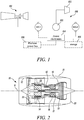
- FIG. 1 An example of a cabin blower system wherein the compressor is free to rotate at a speed that matches the needs of the aircraft, regardless of the engine core speed, is illustrated in figure 1 and comprises a variable drive system 100 which receives mechanical power from a gas turbine engine 101 and provide mechanical power to a compressor 102 of a cabin blower.
- the variable drive system 100 includes two electrical machines (MG1 and MG2) and a summing gearbox 103 configured such that altering the power flow between the two machines (with one generating power and one motoring using power from the other) by means of a power management system 104 varies the output speed of the cabin blower compressor 102.
- the power management system 104 may include batteries 105, and/or a platform power bus 106 to receive power from an external power source.
- the illustrated cabin blower system has the potential to operate in an electrical-only mode, or in other words when the gas turbine engine is off, thereby reducing fuel consumption and limiting emissions, but features a major drawback: the power capacity provided by the two electrical machines is limited as one of the two electrical machines is constrained to rotate with the gas turbine (which, by definition is not rotating in the electrical-only mode).
- the concept of the cabin blower is to maximise efficiency and minimise weight of the electrical machines, the remaining electrical machine will have a power rating below that of the blower compressor, thereby limiting the capability of the motor in this mode.
- European Patent Application Publication EP 3628848 A1 relates to a drive assembly for an aircraft auxiliary power unit (APU).
- the APU is a small gas turbine engine for driving accessories.
- European Patent Application Publication EP 2320067 B2 relates to an aircraft starter generator.
- an aircraft cabin blower system comprising:
- the gas turbine engine may be a main gas turbine engine of the aircraft. That is, it may be one of one or more gas turbine engines arranged to provide propulsive thrust for the aircraft.
- the gas turbine engine may be configured for attachment to a wing of the aircraft.
- the electric variator may comprise a first electrical machine, a second electrical machine, and a power management system, the first and the second electrical machines being independently configured to work as electric motors and/or as power generators.
- the second electric machine may be connected to the compressor of the cabin blower.
- the first electrical machine and the second electrical machine may be connected to the power management system.
- the first electrical machine may be connected to the summing gearbox through a first auxiliary transmission
- the second electrical machine may be connected to the summing gearbox through a second auxiliary transmission.
- the first one-way rotation device may include a freewheel with a ratchet device comprising sprung pawls.
- the first one-way rotation devices may include a sprag clutch.
- the first one-way rotation device may be arranged such that centrifugal forces move the sprung pawls or sprags into an unlocked position when the main transmission rotates in the forward direction.
- the first one-way rotation device may apply a counter-torque on to the summing gearbox when the gas turbine engine is not running and a torque in the reverse direction is applied.
- the aircraft cabin blower system may further comprise a second one-way rotation device adapted to permit free rotation of the second auxiliary transmission in the forward direction and to prevent rotation of the second auxiliary transmission in the reverse direction opposite to the forward direction.
- the second one-way rotation device may include a freewheel with a ratchet device comprising sprung pawls, or a sprag clutch.
- the second one-way rotation device may be arranged such that centrifugal forces move the sprung pawls or sprags into an unlocked position when the main transmission rotates in the forward direction.
- the summing gearbox may be an epicyclic gearbox, or a differential gear.
- the aircraft cabin blower system of the first aspect may be used to drive the cabin blower purely electrically by means of the electric variator without running the gas turbine engine.
- the aircraft cabin blower system of the first aspect according to the embodiment comprising two one-way rotation devices may be used to start the gas turbine engine purely electrically by means of the electric variator without running the gas turbine engine.
- a gas turbine engine is generally indicated at 10, having a principal and rotational axis 11.
- the engine 10 comprises a propulsive fan 13 and a core including, in axial flow series, an intermediate pressure compressor 14, a high-pressure compressor 15, combustion equipment 16, a high-pressure turbine 17, an intermediate pressure turbine 18, a low-pressure turbine 19.
- a nacelle 21 generally surrounds the engine 10 and defines both an air intake 12 and a core exhaust nozzle 20.
- upstream and downstream are with respect to the air flow through the compressor.
- front and rear is with respect to the gas turbine engine, i.e. the fan being in the front and the turbine being in the rear of the engine.
- the gas turbine engine 10 works in the conventional manner so that air entering the intake 12 is accelerated by the fan 13 to produce two air flows: a first air flow into the intermediate pressure compressor 14 and a second air flow which passes through a bypass duct 22 to provide propulsive thrust.
- the first airflow is accelerated and compressed by the low pressure compressor 14 and directed into the high pressure compressor 15 where further compression takes place.
- the compressed air exhausted from the high-pressure compressor 15 is directed into the combustion equipment 16 where it is mixed with fuel and the mixture combusted.
- the resultant hot combustion products then expand through, and thereby drive the high, intermediate and low-pressure turbines 17, 18, 19 before being exhausted through the nozzle 20 to provide additional propulsive thrust.
- the high 17, intermediate 18 and low 19 pressure turbines drive respectively the high pressure compressor 15, intermediate pressure compressor 14 and fan 13, each by suitable interconnecting shaft.
- gas turbine engines to which the present disclosure may be applied may have alternative configurations.
- such engines may have an alternative number of interconnecting shafts (e.g. two) and/or an alternative number of compressors and/or turbines.
- the gas turbine engine may comprise a fan, two compressors and two turbines.
- the engine may comprise a gearbox provided in the drive train from a turbine to a compressor and/or fan.
- the fan may be attached to and driven by the low pressure turbine via a power gearbox.
- the power gearbox may be an epicyclic gearbox with a star or planetary configuration.
- low pressure turbine and “low pressure compressor” as used herein may be taken to mean the lowest pressure turbine stages and lowest pressure compressor stages (i.e. not including the fan 13) respectively and/or the turbine and compressor stages that are connected together by the interconnecting shaft with the lowest rotational speed in the engine (i.e. not including the gearbox output shaft that drives the fan 13).
- the "low pressure turbine” and “low pressure compressor” referred to herein may alternatively be known as the “intermediate pressure turbine” and “intermediate pressure compressor”. Where such alternative nomenclature is used, the fan 13 may be referred to as a first, or lowest pressure, compression stage.
- the geometry of the gas turbine engine 10, and components thereof, is defined by a conventional axis system, comprising an axial direction (which is aligned with the main and rotational axis 11), a radial direction (in the bottom-to-top direction in Figure 1 ), and a circumferential direction (perpendicular to the page in the Figure 1 view).
- the axial, radial and circumferential directions are mutually perpendicular.
- Figure 3 illustrates a first embodiment of cabin blower system 30 for an aircraft according to the disclosure.
- the cabin blower system 30 comprises a cabin blower 32 including a compressor 34 configured to provide controlled air to a cabin 36 of the aircraft.
- the cabin blower system 30 further includes a variable drive system 40 connected to the core of a gas turbine engine 110 through a main transmission 50.
- the main transmission may be a mechanical transmission.
- the gas turbine engine 110 may be of the type of the gas turbine engine 10 illustrated with reference to figure 2 , or may be different, as explained before, for example in terms of number of compressors, turbines, interconnecting shafts, and it may, or may not, comprise a power gearbox.
- variable drive system 40 is configured to drive the compressor 34 at a speed independent from, within certain limits, the engine core rotational speed.
- the variable drive system 40 comprises an electric variator 42 and a summing gearbox 44.
- the main transmission 50 receives mechanical power from an accessory gearbox 51 of the gas turbine engine 110 and input mechanical power to the summing gearbox 44.
- the main transmission 50 rotates in a forward direction.
- the summing gearbox 44 further includes an additional mechanical input and an output (or summing output) that drives the cabin blower compressor 34, as explained in detail hereinafter.
- the gas turbine engine which the present disclosure may apply, may be a bypass turbofan comprising multiple shafts, each of which may provide mechanical power to the main transmission 50, either directly or through an accessory gearbox.
- the electric variator 42 comprises a first electrical machine MG1, a second electrical machine, and a power management system 46.
- the first electrical machine MG1 is configured to work as an electric motor or as a power generator.
- the second electrical machine MG2 is configured to work as an electric motor or as a power generator.
- the first and second electrical machines MG1, MG2 are configured to independently work as electric motor or power generator.
- the power management system 46 interconnects the first electrical machine MG1 and second electrical machine MG2 through an electrical transmission 48 (illustrated in double line in figure 3 ) and controls whether each of the first and second electrical machines MG1, MG2 work as electric motor or power generator.
- the power management system 46 can include electric energy storage 47, in the form for example of one or more batteries, capacitors or similar.
- the power management system 46 can further output electrical power to an external electrical load 49, such as for example aircraft control surface actuators, anti-ice heating, control systems / avionics, galley power.
- the first electrical machine MG1 is connected to the summing gearbox 44 through a first auxiliary transmission 52.
- the second electrical machine MG2 is connected to the summing gearbox 44 through a second auxiliary transmission 54.
- the first and second auxiliary transmissions 52, 54 are mechanical transmissions.
- a mechanical transmission may be anything from a simple shaft up to a complex gearbox.
- the main transmission 50 and second auxiliary transmissions 54 rotates in a forward direction.
- the first auxiliary transmission 52 may rotate in the forward direction, or in a reverse (backward) direction, depending on a speed ratio desired between the gas turbine engine 110 and the cabin blower 32.
- the summing gearbox 44 features two inputs (the main transmission 50 and the first auxiliary transmission 52) and one output (the second auxiliary transmission 54).
- ⁇ load K 1 ⁇ GT + K 2 ⁇ MG 1
- ⁇ load is the rotational speed of an output shaft of the second auxiliary transmission 54 connected to the compressor 34 of the cabin blower 32
- ⁇ GT is the rotational speed of the main transmission 50
- ⁇ MG 1 is the rotational speed of the first auxiliary transmission 52
- K 1 and K 2 are some fixed constants.
- the speed of the cabin blower compressor 34 can be varied relative to the speed of the gas turbine 110 by addition or subtraction of speed at the first electrical machine MG1 with the second electrical machine MG2 supplying power to the first electrical machine MG1 or consuming power generated by the first electrical machine MG1 depending on whether the first electrical machine MG1 is generating (when subtracting speed) or motoring (when adding speed).
- electrical power can be transferred through the electrical transmission 48 between the first and second electrical machines MG1, MG2, depending on whether the first electrical machine MG1 and the second electrical machine MG2 act as a generator or as a motor.
- the power management system 46 may control the second electrical machine MG2 to act as a generator and feed back power to the first electrical machine MG1 through the electrical transmission 48.
- the cabin blower system 30 further includes a first one-way rotation device 62.
- the first one-way rotation device 62 is arranged along the main transmission 50 and is configured to allow free rotation of the main transmission 50 in the forward direction and to prevent rotation of the main transmission 50 in a reverse direction opposite to the forward direction.
- the first one-way rotation device 62 is arranged along the main transmission 50 between the gas turbine engine 110 and the summing gearbox 44, for example between the accessory gearbox 51 and the summing gearbox 44. In an embodiment, the first one-way rotation device 62 is arranged closer to the summing gearbox 44 than to the accessory gearbox 51, for example at the accessory gearbox.
- the first one-way rotation device 62 may be a freewheel, utilising sprung pawls and a ratchet, or a sprag clutch, utilising friction between sprags and inner and out cylinders. It is preferable to arrange that centrifugal forces move the pawls or sprags into the unlocked position for normal operating speeds, as this reduces the wear on the device.
- Figure 4 illustrates the first one-way rotation device 62 according to a first embodiment.
- the first one-way rotation device 62 is of the sprag clutch-type 60 and comprises an inner race 66, an outer race 68, and a plurality of sprags 67 and associated springs 69 circumferentially arranged therebetween (for sake of simplicity only some of the sprags 67 and associated springs 69 are illustrated).
- the spring 69 pushes the associated sprag 67 in abutment against the inner race 66.
- the sprag 67 are substantially cam shaped wedges arranged at an angle with respect to the inner race 66 to allow free rotation of the inner race 66 with respect to the outer race 68 in one direction only.
- torque is applied in opposite direction, friction between the sprags 67 and the inner race 66 (or the outer race 68, depending on the geometry of the first one-way rotation device 62) prevents rotation.
- first one-way rotation device 62 can be implemented according to the disclosure with either the inner race 66 or the outer race 68 connected to, and thereby driven by, the main transmission 50.
- the sprags 67 and associated springs 69 may be integral with either the inner race 66 or the outer race 68.
- the first one-way rotation device 62 is configured to allow rotation of the main transmission 50 in the forward direction F.
- the first one-way rotation device is configured to prevent rotation of the main transmission 50 and, when preventing such rotation, applies a positive reaction torque on the summing gearbox 44.
- the sprags 67 and associated springs 69 are integral with the outer race 68, which in turn is connected to the main transmission 50, such that in normal operation condition, i.e. when the main transmission 50 rotates in the forward direction F, centrifugal forces move the sprags 67 into an unlocked position, as this reduces the wear on the device.
- the sprags 67 and associated springs 69 are integral with the inner race 66, which in turn are connected to the main transmission 50, such that in normal operation condition, i.e. when the main transmission 50 rotates in the forward direction F, centrifugal forces move the sprags 67 into an unlocked position, as this reduces the wear on the device.
- Figure 5 illustrates the first one-way rotation device 62 according to a second embodiment.
- the first one-way rotation device 62 is of the ratchet and pawl-type 70 and comprises an inner race 71, an outer race 73, and a plurality of pawls 75 housed in the outer race 73.
- the inner race 71 features a radially external profile 76 shaped to present a plurality of teeth 77.
- the pawls 75 are pushed by springs 78 to follow the radially external profile 76 as the outer race 73 rotates in one direction relative to the inner race 71.
- the pawls 75 drop between two adjacent teeth 77 preventing the outer race 73 from rotating relative to the inner race 71.
- the outer race 73 is connected to the main transmission 50, such that as the main transmission 50 rotates in the forward direction, the outer race 73 rotates too.
- the inner race 71 is stationary and does not rotate along with the main transmission 50.
- centrifugal force acts against the springs 78 allowing the pawls 75 not to contact the radially external profile 76 of the inner race 71, thereby reducing wear on the pawls 75 and the teeth 77 of the inner ring 71.
- the pawls 75 engage with the teeth 77 locking the main transmission 50.
- the first one-way rotation device 62 allows the main transmission 50 to freely rotate and substantially performs no function.
- the one-way rotation device 62 is advantageous in the case where it is desired to operate the cabin blower compressor 34 from the aircraft's electrical power without running the gas turbine engine 110. Running the cabin blower compressor 34 from electrical power potentially reduces local emissions at airports when the aircraft is parked and cabin air conditioning is required.
- the torque T GT provided by the gas turbine engine 110 to the cabin bower system is zero.
- T LOAD + T MG 2 0, without the one-way rotation device 62, it is only possible to drive the cabin blower compressor 34 from the second electrical machine MG2.
- the torque applied to the load is limited by the capability of the second electrical machine MG2.
- the torque at the gearbox and hence at the first electrical machine MG1 must be zero as, when inactive, the gas turbine engine 110 cannot exert any torque.
- the first electrical machine MG1 cannot give any assistance.
- T GT K 1 K 2 T MG 1 .
- Figure 6 illustrates a second embodiment of cabin blower system 300 for an aircraft according to the disclosure.
- the cabin blower system 300 of the second embodiment is substantially similar to the cabin blower 30 of the first embodiment illustrated in figure 3 and differs from it only for the presence of a second one-way rotation device 64 arranged along the second auxiliary transmission 54.
- a second one-way rotation device 64 arranged along the second auxiliary transmission 54.
- the second one-way rotation device 64 is configured to allow free rotation of the second auxiliary transmission 54 in the forward direction and to prevent rotation of the second auxiliary transmission 54 in a reverse direction opposite to the forward direction.
- the second one-way rotation device 64 may be a freewheel, utilising sprung pawls and a ratchet, or a sprag clutch, utilising friction between sprags and inner and out cylinders, of the type illustrated with reference to figures 4 and 5 , and therefore the second one-way rotation device 64 will not be described again in relation to figure 6 .
- the second one-way rotation device 64 is advantageous to start the gas turbine engine 110 using the cabin blower 32, therefore removing the need for a separate starter motor and reducing the weight and complexity of the powerplant.
- the first one-way rotation device 62 permits this rotation and torque transmission because it only resists reverse rotation of the main transmission 50.
- An electrically powered start may be achieved using power supplied from the aircraft electrical network.
- the ultimate source of the power may be on-board battery storage, another on board electrical generation device or externally connected power.
- a method of starting the gas turbine engine 110 is proposed where first electrical machine MG1 provides the motive power.
- the second one-way rotation device 64 prevents reverse rotation of the cabin blower compressor 34 and the second electrical machine MG2 and provides a counter torque such that the first electrical machine MG1 can be used to start the gas turbine engine 110 by motoring in reverse.
- T MG 1 and ⁇ MG 1 are both negative. Being driven in the forward direction, until self-sustaining, ⁇ GT is positive and T GT is negative.
- the second one-way rotation device 64 is optional as there are other ways of achieving a start without the second one-way rotation device 64 being present.
- an electric start could be achieved by driving both the first electric machine MG1 and the second electric machine MG2.
- the second electric machine MG2 would be driven to a low speed, to provide the necessary counter torque without wasting energy by spinning the cabin blower compressor 34 at excessive speeds.
- the first electrical machine MG1 and the gas turbine engine 110 and the second electrical machine MG2 and the cabin blower compressor 34.
- they may be connected by numerous methods, of which co-axial mounting on the same shaft is only one.
- the electrical machines (MG1 and MG2) could be geared to the shaft through another item.
- the second electrical machine MG2 may be geared to a shaft connecting the summing gearbox output to the blower compressor, or a secondary gearbox may split the summing gearbox output to two shafts connected to the second electrical machine MG2 and the cabin blower compressor respectively.
- the gearing could be a spur gear, allowing the motor/generator axis of the electrical machines to be offset from and parallel to the shaft; a bevel gear, allowing the motor/ generator axis to be offset and at an angle to the shaft; or an epicyclic gear train, allowing the motor/generator axis to be co-axial with the shaft but with a speed difference.
- the electrical machine could be connected to the shaft by a chain drive. A combination of elements such as these could be used to find a solution that provides the drive ratios that best match the ideal speeds of the first and second electrical machines MG1, MG2, the gas turbine engine 110 and cabin blower compressor 34, and the packaging requirements of the overall cabin blower system 30, 300 and gas turbine engine 110.
- the summing gearbox 44 may be an epicyclic gearbox, or a differential gear, similar to those used in the automotive industry.
- An epicyclic gearbox may have the advantage over a differential gear of offering a higher power capability for a given gearbox weight.
- Figure 7 illustrates an epicyclic gearbox 400 that may be used as summing gearbox.
- the epicyclic gearbox 400 comprises a sun gear 402, a plurality of planet gears 404, a carrier 406 and a ring gear 408. Radially outwardly of the sun gear 402 and intermeshing therewith is the plurality of planet gears 404 that are coupled together by the carrier 406.
- the planet carrier 406 constrains the planet gears 404 to precess around the sun gear 402 in synchronicity whilst enabling each planet gear 404 to rotate about its own axis.
- Radially outwardly of the planet gears 404 and intermeshing therewith is the ring gear 408.
- the designation of which arm of the epicyclic gearbox is the summing output is a design choice and values of K1 and K2 can equally be found if the carrier 406 or the sun gear 402 is defined as the summing output.
- Figure 8 illustrates a differential gear 500 that may be used as summing gearbox.
- the differential gear 500 comprises a cage, or casing, 502 geared to a shaft 504 which rotates with speed ⁇ 1 by a bevel gear set 506.
- the differential gear has a reduction ratio R such that the rotation speed of the cage 502 is ⁇ 1 / R .
Landscapes
- Engineering & Computer Science (AREA)
- Chemical & Material Sciences (AREA)
- Combustion & Propulsion (AREA)
- Aviation & Aerospace Engineering (AREA)
- Mechanical Engineering (AREA)
- General Engineering & Computer Science (AREA)
- Health & Medical Sciences (AREA)
- General Health & Medical Sciences (AREA)
- Pulmonology (AREA)
- Structures Of Non-Positive Displacement Pumps (AREA)
Applications Claiming Priority (1)
| Application Number | Priority Date | Filing Date | Title |
|---|---|---|---|
| GBGB2007576.8A GB202007576D0 (en) | 2020-05-21 | 2020-05-21 | Aircraft cabin blower system |
Publications (1)
| Publication Number | Publication Date |
|---|---|
| EP3912912A1 true EP3912912A1 (fr) | 2021-11-24 |
Family
ID=71406387
Family Applications (1)
| Application Number | Title | Priority Date | Filing Date |
|---|---|---|---|
| EP21169779.2A Withdrawn EP3912912A1 (fr) | 2020-05-21 | 2021-04-22 | Système de ventilateur de cabine d'aéronef |
Country Status (3)
| Country | Link |
|---|---|
| US (1) | US11698023B2 (fr) |
| EP (1) | EP3912912A1 (fr) |
| GB (1) | GB202007576D0 (fr) |
Cited By (2)
| Publication number | Priority date | Publication date | Assignee | Title |
|---|---|---|---|---|
| EP4197912A1 (fr) * | 2021-12-17 | 2023-06-21 | Rolls-Royce plc | Système de pompage |
| US12565320B2 (en) | 2023-08-21 | 2026-03-03 | Rolls-Royce Plc | Air pressurisation system |
Families Citing this family (2)
| Publication number | Priority date | Publication date | Assignee | Title |
|---|---|---|---|---|
| EP4039586B1 (fr) * | 2021-02-05 | 2023-09-27 | Goodrich Actuation Systems SAS | Ensemble actionneur |
| US12571349B2 (en) * | 2022-07-26 | 2026-03-10 | Rolls-Royce Corporation | Shaft couple for rapid start |
Citations (4)
| Publication number | Priority date | Publication date | Assignee | Title |
|---|---|---|---|---|
| US4900231A (en) * | 1986-05-30 | 1990-02-13 | The Boeing Company | Auxiliary compressor air supply for an aircraft |
| EP1270293A2 (fr) * | 2001-06-25 | 2003-01-02 | Denso Corporation | Equipement fonctionnel combiné de véhicule automobile |
| EP2320067A2 (fr) * | 2009-11-04 | 2011-05-11 | Kawasaki Jukogyo Kabushiki Kaisha | Alternateur-démarreur d'avion |
| EP3628848A1 (fr) | 2018-09-28 | 2020-04-01 | United Technologies Corporation | Amplification à engrenage différentiel d'une unité d'alimentation auxiliaire |
Family Cites Families (7)
| Publication number | Priority date | Publication date | Assignee | Title |
|---|---|---|---|---|
| US4514976A (en) * | 1980-06-02 | 1985-05-07 | Rockwell International Corporation | Integrated auxiliary power and environmental control unit |
| ES2363897B1 (es) * | 2008-10-24 | 2012-07-04 | Airbus Operations, S.L. | Unidad de potencia auxiliar (apu) de una aeronave |
| GB201506398D0 (en) * | 2014-12-11 | 2015-05-27 | Rolls Royce Plc | Cabin blower system |
| US10208675B2 (en) | 2017-03-15 | 2019-02-19 | The Boeing Company | Hybrid drive system for transferring power from a gas turbine engine of an aircraft |
| GB2570478A (en) | 2018-01-26 | 2019-07-31 | Rolls Royce Plc | Cabin blower system |
| GB2570475B (en) | 2018-01-26 | 2020-04-08 | Rolls Royce Plc | Cabin blower system |
| GB2570477A (en) | 2018-01-26 | 2019-07-31 | Rolls Royce Plc | Cabin blower system |
-
2020
- 2020-05-21 GB GBGB2007576.8A patent/GB202007576D0/en not_active Ceased
-
2021
- 2021-04-22 EP EP21169779.2A patent/EP3912912A1/fr not_active Withdrawn
- 2021-04-30 US US17/245,163 patent/US11698023B2/en active Active
Patent Citations (5)
| Publication number | Priority date | Publication date | Assignee | Title |
|---|---|---|---|---|
| US4900231A (en) * | 1986-05-30 | 1990-02-13 | The Boeing Company | Auxiliary compressor air supply for an aircraft |
| EP1270293A2 (fr) * | 2001-06-25 | 2003-01-02 | Denso Corporation | Equipement fonctionnel combiné de véhicule automobile |
| EP2320067A2 (fr) * | 2009-11-04 | 2011-05-11 | Kawasaki Jukogyo Kabushiki Kaisha | Alternateur-démarreur d'avion |
| EP2320067B1 (fr) | 2009-11-04 | 2018-08-22 | Kawasaki Jukogyo Kabushiki Kaisha | Alternateur-démarreur d'avion |
| EP3628848A1 (fr) | 2018-09-28 | 2020-04-01 | United Technologies Corporation | Amplification à engrenage différentiel d'une unité d'alimentation auxiliaire |
Cited By (4)
| Publication number | Priority date | Publication date | Assignee | Title |
|---|---|---|---|---|
| EP4197912A1 (fr) * | 2021-12-17 | 2023-06-21 | Rolls-Royce plc | Système de pompage |
| US20230193776A1 (en) * | 2021-12-17 | 2023-06-22 | Rolls-Royce Plc | Pumping system |
| US12116899B2 (en) * | 2021-12-17 | 2024-10-15 | Rolls-Royce Plc | Variable speed pumping system with electric pump motor generator |
| US12565320B2 (en) | 2023-08-21 | 2026-03-03 | Rolls-Royce Plc | Air pressurisation system |
Also Published As
| Publication number | Publication date |
|---|---|
| US11698023B2 (en) | 2023-07-11 |
| GB202007576D0 (en) | 2020-07-08 |
| US20210362859A1 (en) | 2021-11-25 |
Similar Documents
| Publication | Publication Date | Title |
|---|---|---|
| US11560233B2 (en) | Hybrid aircraft propulsion power plants | |
| US11698023B2 (en) | Aircraft cabin blower system | |
| EP3835562B1 (fr) | Système de propulsion hybride d'aéronef | |
| EP3736423A1 (fr) | Système de propulsion d'aéronef électrique hybride | |
| CA2963776C (fr) | Turbine hybride gaz-electricite | |
| EP3957843B1 (fr) | Moteur à turbine à gaz hybride avec moteur électrique et générateur électrique | |
| EP3987166B1 (fr) | Boîte d'engrenages pour moteur à turbine à corps de suralimentation | |
| EP3910174A1 (fr) | Moteur de turbine à gaz à flux inverse doté d'un moteur électrique | |
| EP3722577B1 (fr) | Moteur à turbine à gaz à entraînement multiple variable | |
| EP3569507B1 (fr) | Système de propulsion d'avion | |
| US4132064A (en) | Turbine engine with differential gearing between high pressure turbine and compressor | |
| US11466623B2 (en) | Engine with start assist | |
| EP4685345A1 (fr) | Boîte de vitesses d'accessoires à accessoires de configuration empilée | |
| EP4197912B1 (fr) | Système de pompage |
Legal Events
| Date | Code | Title | Description |
|---|---|---|---|
| PUAI | Public reference made under article 153(3) epc to a published international application that has entered the european phase |
Free format text: ORIGINAL CODE: 0009012 |
|
| STAA | Information on the status of an ep patent application or granted ep patent |
Free format text: STATUS: THE APPLICATION HAS BEEN PUBLISHED |
|
| AK | Designated contracting states |
Kind code of ref document: A1 Designated state(s): AL AT BE BG CH CY CZ DE DK EE ES FI FR GB GR HR HU IE IS IT LI LT LU LV MC MK MT NL NO PL PT RO RS SE SI SK SM TR |
|
| B565 | Issuance of search results under rule 164(2) epc |
Effective date: 20210910 |
|
| STAA | Information on the status of an ep patent application or granted ep patent |
Free format text: STATUS: THE APPLICATION IS DEEMED TO BE WITHDRAWN |
|
| 18D | Application deemed to be withdrawn |
Effective date: 20220525 |