EP3913261A1 - Dispositif de couplage pour la transmission de couple d'un dispositif d'entraînement à une transmission - Google Patents
Dispositif de couplage pour la transmission de couple d'un dispositif d'entraînement à une transmission Download PDFInfo
- Publication number
- EP3913261A1 EP3913261A1 EP21174643.3A EP21174643A EP3913261A1 EP 3913261 A1 EP3913261 A1 EP 3913261A1 EP 21174643 A EP21174643 A EP 21174643A EP 3913261 A1 EP3913261 A1 EP 3913261A1
- Authority
- EP
- European Patent Office
- Prior art keywords
- coupling device
- drive
- torque
- transmission
- range
- Prior art date
- Legal status (The legal status is an assumption and is not a legal conclusion. Google has not performed a legal analysis and makes no representation as to the accuracy of the status listed.)
- Granted
Links
Images







Classifications
-
- F—MECHANICAL ENGINEERING; LIGHTING; HEATING; WEAPONS; BLASTING
- F16—ENGINEERING ELEMENTS AND UNITS; GENERAL MEASURES FOR PRODUCING AND MAINTAINING EFFECTIVE FUNCTIONING OF MACHINES OR INSTALLATIONS; THERMAL INSULATION IN GENERAL
- F16H—GEARING
- F16H57/00—General details of gearing
- F16H57/02—Gearboxes; Mounting gearing therein
- F16H57/023—Mounting or installation of gears or shafts in the gearboxes, e.g. methods or means for assembly
-
- F—MECHANICAL ENGINEERING; LIGHTING; HEATING; WEAPONS; BLASTING
- F16—ENGINEERING ELEMENTS AND UNITS; GENERAL MEASURES FOR PRODUCING AND MAINTAINING EFFECTIVE FUNCTIONING OF MACHINES OR INSTALLATIONS; THERMAL INSULATION IN GENERAL
- F16D—COUPLINGS FOR TRANSMITTING ROTATION; CLUTCHES; BRAKES
- F16D1/00—Couplings for rigidly connecting two coaxial shafts or other movable machine elements
- F16D1/06—Couplings for rigidly connecting two coaxial shafts or other movable machine elements for attachment of a member on a shaft or on a shaft-end
- F16D1/08—Couplings for rigidly connecting two coaxial shafts or other movable machine elements for attachment of a member on a shaft or on a shaft-end with clamping hub; with hub and longitudinal key
- F16D1/0852—Couplings for rigidly connecting two coaxial shafts or other movable machine elements for attachment of a member on a shaft or on a shaft-end with clamping hub; with hub and longitudinal key with radial clamping between the mating surfaces of the hub and shaft
- F16D1/0864—Couplings for rigidly connecting two coaxial shafts or other movable machine elements for attachment of a member on a shaft or on a shaft-end with clamping hub; with hub and longitudinal key with radial clamping between the mating surfaces of the hub and shaft due to tangential loading of the hub, e.g. a split hub
-
- H—ELECTRICITY
- H02—GENERATION; CONVERSION OR DISTRIBUTION OF ELECTRIC POWER
- H02K—DYNAMO-ELECTRIC MACHINES
- H02K7/00—Arrangements for handling mechanical energy structurally associated with dynamo-electric machines, e.g. structural association with mechanical driving motors or auxiliary dynamo-electric machines
- H02K7/003—Couplings; Details of shafts
-
- H—ELECTRICITY
- H02—GENERATION; CONVERSION OR DISTRIBUTION OF ELECTRIC POWER
- H02K—DYNAMO-ELECTRIC MACHINES
- H02K7/00—Arrangements for handling mechanical energy structurally associated with dynamo-electric machines, e.g. structural association with mechanical driving motors or auxiliary dynamo-electric machines
- H02K7/10—Structural association with clutches, brakes, gears, pulleys or mechanical starters
- H02K7/116—Structural association with clutches, brakes, gears, pulleys or mechanical starters with gears
-
- F—MECHANICAL ENGINEERING; LIGHTING; HEATING; WEAPONS; BLASTING
- F16—ENGINEERING ELEMENTS AND UNITS; GENERAL MEASURES FOR PRODUCING AND MAINTAINING EFFECTIVE FUNCTIONING OF MACHINES OR INSTALLATIONS; THERMAL INSULATION IN GENERAL
- F16H—GEARING
- F16H57/00—General details of gearing
- F16H57/02—Gearboxes; Mounting gearing therein
- F16H2057/02034—Gearboxes combined or connected with electric machines
Definitions
- the invention relates to a coupling device for torque-transmitting coupling of a torque-feeding drive device, in particular a drive motor, which has an output shaft, to a transmission, in particular to a cycloid gear, the coupling device having a coupling device housing for the torque-supporting connection of a transmission torque support element, in particular a transmission housing, of the transmission a drive torque support element of the drive device, in particular a drive housing, as well as a transmission shaft rotatably mounted within the coupling device housing with a drive end which is designed and intended to be non-rotatably connected to an end section of an output shaft of a torque-feeding drive device, the entire coupling device being finished assembled and functional unit can be coupled to a torque-feeding drive device without having to dismantle parts of the coupling device.
- Coupling devices of this type are used to form a transmission system together with a transmission in order, as a result, to couple a torque-feeding drive device, for example a drive motor, to a system to be driven.
- a torque-feeding drive device for example a drive motor
- an output shaft of the drive device must be operatively connected to an input of the system to be driven and, in addition, a torque-supporting connection of a drive torque support element of the drive device, for example a drive housing of a drive motor, to a torque support element of the system to be driven (usually a housing or a bracket) must be established will.
- the end DE 10 2019 003 546 A1 is an adapter for a drive, which has an electric motor with a motor shaft, in particular a rotor shaft, and a gear.
- the adapter has a housing part, an adapter shaft with a ring socket part, a first and a second bearing, a coupling part into which the motor shaft can be inserted, a clamping ring with a radially directed threaded hole, a threaded pin and a ring part.
- the first and second bearings are accommodated in the housing part, the adapter shaft with the ring socket part being rotatably mounted by means of the first and second bearings and the coupling part being positively connected to the adapter shaft and the ring part being received in the housing part or the bearing seat as a flange part with the housing part of the second bearing is connected to form and wherein the threaded pin is at least partially screwed into the radial bore of the clamping ring and partially protrudes into a first bore, in particular radially through the ring part through bore, of the ring part in such a way that the covered by the threaded pin Radial spacing area overlaps both with the radial spacing areas covered by the ring part and with the radial spacing areas covered by the clamping ring.
- a coupling device which is characterized in that a clamping ring with a tangentially extending clamping screw is arranged at the drive end, by means of which the diameter of the axial bore can be reduced, the clamping ring having a one-piece slotted ring, the free ends of which by means of the clamping screw can be brought closer to one another and which is made of aluminum or an aluminum alloy and / or which consists predominantly of aluminum.
- a torsionally rigid, coaxial connection between the transmission shaft and the output shaft of a torque-feeding drive device can be established without having to dismantle parts of the coupling device for this purpose.
- the invention has the very special advantage that the entire coupling device can be coupled by the user with a torque-feeding drive device as an independent unit, fully assembled by the manufacturer and tested for proper functionality.
- it is advantageously not necessary to dismantle the coupling device for coupling to a torque-feeding drive device, which on the one hand simplifies the assembly process and also ensures that the coupling device is used in the state in which it is used (preferably as part of a fully assembled transmission system which has a coupling device according to the invention and a transmission) was tested with regard to its functionality, in particular immediately after its manufacture.
- This embodiment has the particular advantage that the mostly circular cylinder-shaped output shafts of conventional drive motors can be coupled directly. In contrast to, for example, a form-fitting plug connection, the risk of unwanted jamming is also avoided.
- the torque-feeding drive device can in particular be achieved in that the diameter of the axial bore into which the output shaft of a torque-feeding drive device is inserted is reduced by means of the clamping ring, whereby the output shaft of the torque-feeding drive device is clamped.
- the drive end can be designed as a slotted hollow shaft with an axial bore.
- the difference between the outside diameter of the drive end and the diameter of the axial bore is preferably in the range from 3 mm to 5 mm. This enables both sufficient torsional rigidity and a reliable, non-rotatable clamp connection.
- the drive end has at least two axially extending slots.
- the drive end can have exactly two axially extending slots which are arranged radially opposite one another.
- Such a design is particularly advantageous with regard to an unbalance-free rotation of the transmission shaft, but at the same time a reliable, non-rotatable clamp connection is made possible.
- the slots are axially just as long as the axial bore.
- the drive end is designed and intended to be rotatably connected to an output shaft of a torque-feeding drive device, which has a diameter of x mm, with the axial bore in the Output shaft is inserted directly and the axial bore (before clamping, in particular before reducing the diameter, for example by means of a clamping ring) has a diameter in the range from x + 2/100 mm to x + 8/100 mm.
- the drive end is designed and intended to be non-rotatably connected to an output shaft of a torque-feeding drive device, which has a diameter of x mm, and that a compensating sleeve with a wall thickness of y mm is inserted into the axial bore, in which the output shaft can be inserted directly, the axial bore (before clamping, in particular before reducing the diameter, for example by means of a clamping ring) having a diameter in the range from x + y + 2/100 mm to x + y + 8/100 mm .
- X is preferably in the range from 5 mm to 50 mm, in particular in the range from 9 mm to 38 mm.
- x can have one of the values 9 mm, 14 mm, 19 mm, 24 mm, 38 mm.
- Y is preferably in the range from 1 mm to 5 mm, in particular in the range from 2 mm to 4 mm.
- a clamping connection that can transmit particularly high torques is guaranteed in particular when the overall fit of all components involved (output shaft, axial bore and, if necessary, compensating sleeve) is in the range of 2/100 mm to 8/100 mm lies.
- the clearance of fit relates to a possible air gap in the radial direction (before clamping, in particular before reducing the diameter, for example by means of a clamping ring). If the total fit is greater than 8/100, the transmittable torque drops very significantly.
- a total fit that is less than 2/100 mm is at least not disadvantageous with regard to the torque that can be transmitted, but assembly is then no longer easily possible because the individual parts (output shaft in axial bore or compensating sleeve in axial bore and output shaft in Compensation sleeve) can no longer simply be plugged into one another before the clamping screw of the clamping ring is tightened.
- the diameter of the output shaft is not important. Rather, this area is largely independent of the diameter of the output shaft; at least if this is in the range from 5 mm to 50 mm.
- the transmission shaft has a circumferential groove on its outside.
- the circumferential groove can be arranged axially adjacent to the slots. It is also possible, for example, for the slots to protrude axially into the circumferential groove or to extend axially completely through the groove.
- the axially extending slots begin at the free end of the transmission shaft and end at the lowest point of the groove.
- the axially extending slots begin at the free end of the transmission shaft, go completely through the groove and then end.
- the groove has the very special advantage that the sections of the drive end of the transmission shaft can be placed particularly well on the output shaft, for example by means of a clamping ring.
- the circumferential groove is semicircular in cross section.
- the circumferential groove in cross section has a relative to
- Radial direction at an angle different from zero degrees, in particular straight, flank can in particular be in the range from 50 degrees to 70 degrees. It is particularly advantageous if the angle is 60 degrees.
- the circumferential groove can have a further, curved, in particular concavely curved, flank in cross section.
- the circumferential groove has a radial depth in the range from 1 mm to 4 mm, in particular 2 mm.
- the difference between the outer diameter of the drive end and the diameter of the axial bore in the plane of the groove is in the range from 1 mm to 3 mm.
- a clamping ring with a tangentially extending clamping screw is arranged on the drive end, by means of which the diameter of the axial bore can be reduced.
- a clamping ring makes it possible to couple an output shaft to the transmission shaft after the drive housing of a drive motor has been connected to the coupling device housing.
- the coupling device housing can have an opening, in particular radial or tangential, through which a tool can be guided to a head of the clamping screw.
- the clamping ring preferably has only a single clamping screw, which enables simple assembly (in particular with regard to the fact that the drive housing was already connected to the coupling device housing at the time the clamping connection was established).
- the clamping ring has a one-piece slotted ring, the free ends of which can be brought closer together by means of the clamping screw.
- the ring is made from aluminum or an aluminum alloy. and / or when the ring consists predominantly of aluminum.
- the ring consists of an aluminum alloy according to EN AW-7075. It has been shown that such a clamping ring can be used to produce a clamping connection between the output shaft and the transmission shaft, by means of which a significantly higher torque can be transmitted than when using a clamping ring made of a different material, in particular steel, which otherwise has the same dimensions.
- the use of one clamping ring is different from one another Material, in particular steel, is not excluded according to the invention.
- the ratio of an outer diameter of the ring to an inner diameter of the ring is in the range from 1.5 to 3.0, in particular in the range from 1.8 to 2.6.
- a larger ratio disadvantageously results in a larger rotational inertia.
- no better clamping is achieved, since with a larger ratio the inherent rigidity of the ring, which has to be overcome by means of the clamping screw, increases disproportionately.
- the axial width of the ring is in the range of 0.4 to 0.7 times the inner diameter of the ring. This enables the use of a sufficiently thick clamping screw, while at the same time only a small amount of axial installation space is required.
- the coupling device housing is designed to be rotationally symmetrical at least in a partial section. This has the very special advantage of a particularly compact design. Also with a view to the most compact possible construction, the coupling device housing can have a bell shape or a truncated cone shape at least in a partial section on the outside. Such a shape has the further advantage that simple cleaning is made possible.
- the coupling device housing can be constructed in several parts.
- the coupling device housing can have a main section (in particular in the shape of a bell or a truncated cone) and a motor flange attached to it.
- the motor flange can have through bores and / or threaded bores.
- the coupling device housing must be designed to be sufficiently stable in order to be able to support the torques that occur.
- the coupling device housing can advantageously be made in particular from steel or from titanium or from stainless steel or from aluminum.
- the coupling device housing can be produced from a material that contains steel or titanium or stainless steel or aluminum.
- the coupling device housing is coated or anodized or burnished at least on the outside.
- Such a design is particularly well protected against external influences such as damage and soiling.
- a transmission system that has a transmission, in particular a Cycloid gear, and includes a coupling device according to the invention.
- the transmission system can advantageously be manufactured as a preassembled and ready-to-use structural unit that can be assembled at the place of use without having to dismantle components of the transmission system for this purpose.
- the transmission shaft has an output end which is designed and intended to be operatively coupled to a transmission input of the transmission.
- the output end can have a toothing that meshes with at least one toothed wheel of the transmission.
- the transmission can be a cycloid transmission.
- an external toothing of the output end of the transmission shaft is in meshing tooth engagement with external toothing of the eccentric shafts of the cycloid gear when the coupling device is coupled to the cycloid gear.
- the transmission shaft can advantageously be designed and arranged such that when the coupling device housing is connected to a transmission torque support element, an operative connection between the transmission shaft and the transmission is established automatically, in particular according to the principle of a plug connection.
- the transmission shaft is preferably rotatably supported by means of at least one roller bearing. This advantageously ensures a loss-free torque transmission.
- a drive system that contains a torque-feeding drive device and a transmission system according to the invention is particularly advantageous.
- the drive device can be a drive motor, in particular an electric drive motor.
- the drive motor can be provided in particular that the drive motor is coupled directly to the coupling device.
- the drive device it is also possible, for example, for the drive device to have a drive motor, in particular an electric drive, which is coupled to the coupling device only indirectly, namely, for example, via a further transmission.
- the drive device can generally have a further transmission that is coupled directly to the coupling device.
- the drive device can be a geared motor, which contains the further gear, or a geared motor, which has the further gear.
- the drive system can advantageously be manufactured as a preassembled and ready-to-use structural unit that can be assembled on site without having to dismantle components of the drive system for this purpose.
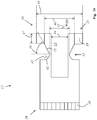
- Fig. 1 shows in a cross-sectional view an embodiment of a transmission system 1 according to the invention, which includes a transmission 2 and an embodiment of a coupling device 3 according to the invention.
- the transmission system 1 serves to couple a torque-feeding drive device 4, namely a drive motor 5 in this exemplary embodiment, to a system 6 to be driven.
- a torque-feeding drive device 4 namely a drive motor 5 in this exemplary embodiment
- two active compounds are produced here.
- an active connection (which is reduced or translated by the gear 2) of an output shaft 7 of the drive motor 5 with a drive input (not shown) of the system 6 to be driven is established via the transmission shaft 15, the drive input of the system 6 to be driven being directly connected to a transmission output 8 of the Transmission 2 is operatively connected.
- a torque-supporting connection of a drive torque support element namely in this embodiment a drive housing 9 of the drive device 4 to a torque support element, for example to a holding device 27 or to a housing of the system 6 to be driven, is established.
- the coupling device 3 has a coupling device housing 11 for the torque-supporting connection of a transmission torque support element 12 of the transmission 2 to the drive housing 9 of the drive device 4.
- That Coupling device housing 11 is constructed in several parts and has a motor flange 13 (fastened by means of fastening screws (not shown)).
- a transmission shaft 15 rotatably mounted by means of a roller bearing 14.
- a shaft seal 17 is arranged between the coupling device housing 11 and the transmission shaft 15 to seal the interior 16 of the coupling device 3.
- the transmission shaft 15 has an output end 18 which is operatively coupled to a transmission input 19 of the transmission 2.
- the output end 18 can have an external toothing 36 which meshes with at least one toothed wheel of the transmission 2.
- the transmission 2 can be a cycloid transmission.
- an external toothing 36 of the output end 18 of the transmission shaft 15 is in meshing tooth engagement with external toothing of the eccentric shafts of the cycloid gear.
- the transmission shaft 15 also has a drive end 20 which is designed and intended to be non-rotatably and non-positively connected to the output shaft 7 in a non-rotatable manner.
- the drive end 20 is designed as a slotted hollow shaft (preferably with two axially extending slots, which are in the Figure 1 are not shown) into which the output shaft 7 can be inserted and clamped by means of a clamping ring 21, which has a clamping screw 22, in order to produce a non-rotatable connection.
- the drive end 20 has an axial bore 33.
- the axial bore 33 (before tightening the clamping screw 22) preferably has a diameter in the range from x + 2/100 to x + 8/100 mm, the output shaft 7 having a diameter of x mm. In this way, by subsequently tightening the clamping screw 22 of the clamping ring 21, a particularly permanent and secure clamping connection is established.
- the motor flange 13 has a (in Figure 3 shown) tangential opening 10, through which the head of the clamping screw 22 can be reached with a tool, for example an Allen key or an internal multi-tooth wrench, in order to establish the clamping connection after the drive housing 9 of the drive device 4 has been connected to the motor flange 13 by means of several fastening screws 23 .
- a tool for example an Allen key or an internal multi-tooth wrench
- the system 6 to be driven is fastened to the transmission system 1 by means of retaining screws 24.
- retaining screws 24 In the coupling device housing 11 there are axial threaded bores 25 into which the retaining screws 24 are screwed in.
- the retaining screws 24 run through flange-like through bores 26 of a holding device 27 of the system 6 to be driven and through corresponding further through bores 28 of the transmission torque support element 12.
- the transmission shaft 15 has a circumferential groove 32 on its outside.
- the groove 32 and the end of the axial slots are arranged in the same plane perpendicular to the axial direction.
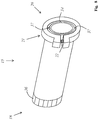
- Fig. 2 shows the transmission system 1 alone in a different rotational position.
- the transmission 2 is screwed to the coupling device 1 by means of several connecting screws 29.
- the connecting screws 29 run through further through bores 30 of the flange-like transmission torque support element 12 and are screwed into threaded bores 31 of the coupling device housing 11, whereby the transmission torque support element 12 and the coupling device housing 11 are connected to one another in a rotationally fixed manner.
- the threaded bores 31 are arranged on the front side in the coupling device housing 11 and run in the axial direction.
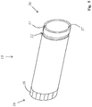
- Fig. 3 shows the coupling device 3 of the first embodiment from the outside.
- the motor flange 13 has a tangential opening 10 through which the head of the clamping screw 22 can be reached with a tool, for example a hexagon socket wrench or a multi-toothed wrench, in order to establish the clamping connection after the drive housing 9 with the motor flange 13 was connected.
- a closure for example a threaded pin that can be screwed into a thread of the opening 10, can be provided.
- Fig. 4 shows a cross-sectional view of a second exemplary embodiment of a transmission system 1 according to the invention including a system 6 to be driven and a drive device 4 that feeds in torque.
- a compensating sleeve 34 with a wall thickness of y mm is inserted into the axial bore 33.
- the output shaft 7 is inserted directly into the compensating sleeve 34, the axial bore preferably having a diameter in the range from x + y + 2/100 mm to x + y + 8/100 mm (before tightening the clamping screw 22).
- the clamping screw 22 of the clamping ring 21 by subsequently tightening the clamping screw 22 of the clamping ring 21, a particularly reliable and secure clamping connection is established.
- the motor flange 13 has threaded bores 35 into which the Fastening screws 23 for fixing the drive housing 9 to the coupling device housing 11 are screwed.
- Fig. 5 shows a first embodiment of a transmission shaft 15 of a coupling device 3 according to the invention.
- the transmission shaft 15 has an output end 18 which can be operatively coupled to a transmission input 19 of a transmission 2.
- the output end 18 can have an external toothing 36.
- the transmission shaft 15 also has a drive end 20 which is designed and intended to be non-rotatably and non-positively connected to an output shaft 7 in a non-rotatable manner.
- the drive end 20 is designed as a slotted hollow shaft into which an output shaft 7 can be inserted and clamped by means of a clamping ring 21 in order to produce a non-rotatable connection.
- the drive end 20 has an axial bore 33 into which an output shaft 7 can be inserted either directly or with the interposition of a compensating sleeve 34.
- the transmission shaft 15 has a circumferential groove 32 on its outside.
- the drive end 20 has exactly two axially extending slots 37 which are open at the free end of the transmission shaft 15 and which are arranged radially opposite one another.
- the axially extending slots 37 begin at the free end of the transmission shaft 15 and extend into the groove 32.
- the axially extending slots 37 begin at the free end of the transmission shaft 15 and end at the lowest point of the groove 32.
- Fig. 6 shows the first embodiment of a transmission shaft 15 together with a clamping ring 21 which has a clamping screw 22.
- Fig. 7 the first embodiment of a transmission shaft 15 of a coupling device 3 according to the invention, into which a compensating sleeve 34 is inserted.
- Fig. 8 shows the first embodiment of a transmission shaft 15 including a clamping ring 21, which has a clamping screw 22 and the compensating sleeve 34 completely inserted.
- Fig. 9 shows a second embodiment of a transmission shaft 15 of a coupling device 3 according to the invention in a cross-sectional view.
- This transmission shaft 15 has an output end 18 which can be operatively coupled to a transmission input 19 of a transmission 2.
- the output end 18 can have an external toothing 36.
- the transmission shaft 15 also has a drive end 20 which is designed and intended to be non-rotatably and non-positively connected to an output shaft 7 in a non-rotatable manner.
- the drive end 20 is designed as a slotted hollow shaft into which an output shaft 7 can be inserted and clamped by means of a clamping ring 21 in order to produce a non-rotatable connection.
- the drive end 20 has an axial bore 33 into which an output shaft 7 (not shown in this figure) can be inserted either directly or with the interposition of a compensating sleeve 34.
- the clamping ring 21 has a one-piece slotted ring 38, the free ends of which by means of the (in Figure 9 not shown) clamping screw 22 are approachable.
- the drive end 20 has exactly two axially extending slots 37 which are open at the free end of the transmission shaft 15 and which are arranged radially opposite one another, which is shown in FIG Figure 9 is not shown.
- the transmission shaft 15 has a circumferential groove 32 on its outside.
- the circumferential groove 32 surrounds the radial bore 33.
- the circumferential groove 32 has, in cross section, an, in particular straight, flank 40 running relative to the radial direction at an angle 39 other than zero degrees.
- the angle 39 is in the range from 50 degrees to 70 degrees.
- the circumferential groove 32 has, in cross section, a further, curved, in particular concavely curved, flank 41 with a radius 42.
- the radius 42 corresponds to the radial depth of the circumferential groove 32.
- the circumferential groove 32 can have a radial depth in the range from 1 mm to 4 mm, in particular 2 mm.
- the difference between the outer diameter 43 of the drive end 20 and the diameter 44 of the axial bore 33 is in the range from 3 mm to 5 mm.
- the ratio of the outer diameter 45 of the ring 38 to an inner diameter 46 of the ring 38 is in the range from 1.5 to 3.0, in particular in the range from 1.8 to 2.6.
- the outer diameter can advantageously be in the range from 30 mm to 90 mm.
- the axial width 47 of the ring 38 is preferably in the range of 0.4 to 0.7 times the inner diameter 46 of the ring 38. This enables the use of a sufficiently thick one Clamping screw, while at the same time only a small amount of axial space is required.
- Fig. 10 shows a third embodiment of a transmission shaft 15 of a coupling device 3 according to the invention in a cross-sectional view.
- the transmission shaft 15 differs from that in FIG Figure 9 transmission shaft 15 shown in that the output end 18 has a larger outer diameter than the drive end 20.
- Fig. 11 shows the third embodiment of a transmission shaft 15 of a coupling device 3 according to the invention in a cross-sectional view, wherein a, preferably slotted, compensating sleeve 34 is inserted into the bore 33.
- Fig. 12 shows an embodiment of a clamping ring 21 for a coupling device 3 according to the invention.
- the clamping ring 21 has a one-piece slotted ring 38, the free ends of which can be brought closer together by means of the clamping screw 22.
- the ratio of the outer diameter 45 of the ring 38 to an inner diameter 46 of the ring 38 is in the range from 1.5 to 3.0, in particular in the range from 1.8 to 2.6.
- the outer diameter can advantageously be in the range from 30 mm to 90 mm.
- the axial width 47 of the ring 38 is preferably in the range of 0.4 to 0.7 times the inner diameter 46 of the ring 38. This enables the use of a sufficiently thick clamping screw, while at the same time only a small axial installation space is required.
- the dimension 48 indicates the diameter of a circle (shown in dashed lines) which is concentric with the ring 38 and which touches the protruding head of the clamping screw 22.
- the dimension 48 is slightly larger than the outer diameter 45 of the ring 38.
Landscapes
- Engineering & Computer Science (AREA)
- General Engineering & Computer Science (AREA)
- Mechanical Engineering (AREA)
- Power Engineering (AREA)
- General Details Of Gearings (AREA)
Applications Claiming Priority (1)
| Application Number | Priority Date | Filing Date | Title |
|---|---|---|---|
| LU101812A LU101812B1 (de) | 2020-05-20 | 2020-05-20 | Ankoppelvorrichtung und Verfahren zum drehmomentübertragenden Ankoppeln einer Antriebsvorrichtung an ein Getriebe |
Publications (3)
| Publication Number | Publication Date |
|---|---|
| EP3913261A1 true EP3913261A1 (fr) | 2021-11-24 |
| EP3913261B1 EP3913261B1 (fr) | 2024-09-11 |
| EP3913261C0 EP3913261C0 (fr) | 2024-09-11 |
Family
ID=71096728
Family Applications (1)
| Application Number | Title | Priority Date | Filing Date |
|---|---|---|---|
| EP21174643.3A Active EP3913261B1 (fr) | 2020-05-20 | 2021-05-19 | Dispositif de couplage pour la transmission de couple d'un dispositif d'entraînement à une transmission |
Country Status (2)
| Country | Link |
|---|---|
| EP (1) | EP3913261B1 (fr) |
| LU (1) | LU101812B1 (fr) |
Families Citing this family (1)
| Publication number | Priority date | Publication date | Assignee | Title |
|---|---|---|---|---|
| US12404017B2 (en) * | 2022-11-02 | 2025-09-02 | Textron Innovations Inc. | Method for improving loss of lube survival |
Citations (3)
| Publication number | Priority date | Publication date | Assignee | Title |
|---|---|---|---|---|
| CN105840791A (zh) * | 2016-04-26 | 2016-08-10 | 捷和电机制品(深圳)有限公司 | 齿轮马达减速机构、清扫刷盘以及清洁车 |
| DE102018204200A1 (de) * | 2018-03-20 | 2019-09-26 | Zf Friedrichshafen Ag | Planetengetriebe mit einer Leitung zum Hindurchführen von Schmier- und/oder Kühlmittel durch das Planetengetriebe |
| DE102019003546A1 (de) | 2018-06-08 | 2019-12-12 | Sew-Eurodrive Gmbh & Co. Kg | Adapter für einen Antrieb und Antrieb |
-
2020
- 2020-05-20 LU LU101812A patent/LU101812B1/de active IP Right Grant
-
2021
- 2021-05-19 EP EP21174643.3A patent/EP3913261B1/fr active Active
Patent Citations (3)
| Publication number | Priority date | Publication date | Assignee | Title |
|---|---|---|---|---|
| CN105840791A (zh) * | 2016-04-26 | 2016-08-10 | 捷和电机制品(深圳)有限公司 | 齿轮马达减速机构、清扫刷盘以及清洁车 |
| DE102018204200A1 (de) * | 2018-03-20 | 2019-09-26 | Zf Friedrichshafen Ag | Planetengetriebe mit einer Leitung zum Hindurchführen von Schmier- und/oder Kühlmittel durch das Planetengetriebe |
| DE102019003546A1 (de) | 2018-06-08 | 2019-12-12 | Sew-Eurodrive Gmbh & Co. Kg | Adapter für einen Antrieb und Antrieb |
Non-Patent Citations (1)
| Title |
|---|
| ANONYMOUS: "Geschlitzte Klemmringe aus Aluminium | MÄDLER Webshop", 2 January 2020 (2020-01-02), XP055841432, Retrieved from the Internet <URL:https://web.archive.org/web/20200102080056/https://maedler.de/product/1643/1625/geschlitzte-klemmringe-aus-aluminium> [retrieved on 20210915] * |
Also Published As
| Publication number | Publication date |
|---|---|
| EP3913261B1 (fr) | 2024-09-11 |
| EP3913261C0 (fr) | 2024-09-11 |
| LU101812B1 (de) | 2021-11-22 |
Similar Documents
| Publication | Publication Date | Title |
|---|---|---|
| EP1266153B1 (fr) | Systeme modulaire d'engrenage | |
| EP1511943A1 (fr) | Gamme de fabrication d'arbres et procede de realisation | |
| DE202012009415U1 (de) | Industriegetriebe | |
| EP1511952B1 (fr) | Entrainement standard, gamme de fabrication a flasque intermediaire | |
| EP2805078B1 (fr) | Accouplement d'arbre et moyeu, adaptateur et moteur d'entrainement | |
| EP3913261B1 (fr) | Dispositif de couplage pour la transmission de couple d'un dispositif d'entraînement à une transmission | |
| DE102019121755A1 (de) | Mehrteiliges Stellelement | |
| EP3913260B1 (fr) | Dispositif d'accouplement destiné à l'accouplement à transfert de couple d'un moteur d'entrainement à une boite de vitesses | |
| EP1360753B1 (fr) | Element dente de moto-reducteur, serie de moto-reducteurs et connexion | |
| EP4323665B1 (fr) | Entraînement comprenant un moteur électrique, une boîte de vitesses et un boîtier adaptateur disposé entre le moteur électrique et la boîte de vitesses | |
| EP1915553B1 (fr) | Adaptateur, engrenage planetaire, entrainement, et procede | |
| DE102020113738A1 (de) | Ankoppelvorrichtung und Verfahren zum drehmomentübertragenden Ankoppeln einer Antriebsvorrichtung an ein Getriebe | |
| EP3913259B1 (fr) | Procédé de fabrication d'un système de changement de vitesses | |
| LU500882B1 (de) | Ankoppelvorrichtung zum drehmomentübertragenden Ankoppeln eines Antriebsmotors an ein Getriebe | |
| EP1741664B1 (fr) | Actionneur pour le positionnement d'une charge | |
| EP4520999A1 (fr) | Actionneur et système avec un actionneur | |
| DE102020113745A1 (de) | Verfahren zum Herstellen eines Getriebesystems | |
| DE102025138136A1 (de) | Adapterwelle | |
| DE102021130361A1 (de) | Ankoppelvorrichtung zum drehmomentübertragenden Ankoppeln eines Antriebsmotors an ein Getriebe | |
| DE102023123909A1 (de) | Aktuator und System mit einem Aktuator | |
| DE102020113724A1 (de) | Ankoppelvorrichtung zum drehmomentübertragenden Ankoppeln eines Antriebsmotors an ein Getriebe | |
| EP4365465A1 (fr) | Dispositif de transmission | |
| DE102025138135A1 (de) | Adapterwelle | |
| EP4702260A1 (fr) | Arbre d'adaptation | |
| DE19814291A1 (de) | Schraube und Werkzeug zum Anziehen und Lösen von Muttern auf Schrauben |
Legal Events
| Date | Code | Title | Description |
|---|---|---|---|
| PUAI | Public reference made under article 153(3) epc to a published international application that has entered the european phase |
Free format text: ORIGINAL CODE: 0009012 |
|
| STAA | Information on the status of an ep patent application or granted ep patent |
Free format text: STATUS: THE APPLICATION HAS BEEN PUBLISHED |
|
| AK | Designated contracting states |
Kind code of ref document: A1 Designated state(s): AL AT BE BG CH CY CZ DE DK EE ES FI FR GB GR HR HU IE IS IT LI LT LU LV MC MK MT NL NO PL PT RO RS SE SI SK SM TR |
|
| B565 | Issuance of search results under rule 164(2) epc |
Effective date: 20211004 |
|
| STAA | Information on the status of an ep patent application or granted ep patent |
Free format text: STATUS: REQUEST FOR EXAMINATION WAS MADE |
|
| 17P | Request for examination filed |
Effective date: 20220523 |
|
| RBV | Designated contracting states (corrected) |
Designated state(s): AL AT BE BG CH CY CZ DE DK EE ES FI FR GB GR HR HU IE IS IT LI LT LU LV MC MK MT NL NO PL PT RO RS SE SI SK SM TR |
|
| STAA | Information on the status of an ep patent application or granted ep patent |
Free format text: STATUS: EXAMINATION IS IN PROGRESS |
|
| 17Q | First examination report despatched |
Effective date: 20221219 |
|
| GRAP | Despatch of communication of intention to grant a patent |
Free format text: ORIGINAL CODE: EPIDOSNIGR1 |
|
| STAA | Information on the status of an ep patent application or granted ep patent |
Free format text: STATUS: GRANT OF PATENT IS INTENDED |
|
| RIC1 | Information provided on ipc code assigned before grant |
Ipc: F16H 57/02 20120101ALN20240315BHEP Ipc: H02K 7/116 20060101ALN20240315BHEP Ipc: H02K 7/00 20060101ALI20240315BHEP Ipc: F16D 1/08 20060101ALI20240315BHEP Ipc: F16H 57/023 20120101AFI20240315BHEP |
|
| INTG | Intention to grant announced |
Effective date: 20240404 |
|
| GRAS | Grant fee paid |
Free format text: ORIGINAL CODE: EPIDOSNIGR3 |
|
| GRAA | (expected) grant |
Free format text: ORIGINAL CODE: 0009210 |
|
| STAA | Information on the status of an ep patent application or granted ep patent |
Free format text: STATUS: THE PATENT HAS BEEN GRANTED |
|
| AK | Designated contracting states |
Kind code of ref document: B1 Designated state(s): AL AT BE BG CH CY CZ DE DK EE ES FI FR GB GR HR HU IE IS IT LI LT LU LV MC MK MT NL NO PL PT RO RS SE SI SK SM TR |
|
| REG | Reference to a national code |
Ref country code: GB Ref legal event code: FG4D Free format text: NOT ENGLISH |
|
| REG | Reference to a national code |
Ref country code: CH Ref legal event code: EP |
|
| REG | Reference to a national code |
Ref country code: DE Ref legal event code: R096 Ref document number: 502021005089 Country of ref document: DE |
|
| REG | Reference to a national code |
Ref country code: IE Ref legal event code: FG4D Free format text: LANGUAGE OF EP DOCUMENT: GERMAN |
|
| U01 | Request for unitary effect filed |
Effective date: 20241011 |
|
| U07 | Unitary effect registered |
Designated state(s): AT BE BG DE DK EE FI FR IT LT LU LV MT NL PT RO SE SI Effective date: 20241029 |
|
| PG25 | Lapsed in a contracting state [announced via postgrant information from national office to epo] |
Ref country code: NO Free format text: LAPSE BECAUSE OF FAILURE TO SUBMIT A TRANSLATION OF THE DESCRIPTION OR TO PAY THE FEE WITHIN THE PRESCRIBED TIME-LIMIT Effective date: 20241211 |
|
| PG25 | Lapsed in a contracting state [announced via postgrant information from national office to epo] |
Ref country code: GR Free format text: LAPSE BECAUSE OF FAILURE TO SUBMIT A TRANSLATION OF THE DESCRIPTION OR TO PAY THE FEE WITHIN THE PRESCRIBED TIME-LIMIT Effective date: 20241212 |
|
| PG25 | Lapsed in a contracting state [announced via postgrant information from national office to epo] |
Ref country code: HR Free format text: LAPSE BECAUSE OF FAILURE TO SUBMIT A TRANSLATION OF THE DESCRIPTION OR TO PAY THE FEE WITHIN THE PRESCRIBED TIME-LIMIT Effective date: 20240911 |
|
| PG25 | Lapsed in a contracting state [announced via postgrant information from national office to epo] |
Ref country code: RS Free format text: LAPSE BECAUSE OF FAILURE TO SUBMIT A TRANSLATION OF THE DESCRIPTION OR TO PAY THE FEE WITHIN THE PRESCRIBED TIME-LIMIT Effective date: 20241211 Ref country code: ES Free format text: LAPSE BECAUSE OF FAILURE TO SUBMIT A TRANSLATION OF THE DESCRIPTION OR TO PAY THE FEE WITHIN THE PRESCRIBED TIME-LIMIT Effective date: 20240911 |
|
| PG25 | Lapsed in a contracting state [announced via postgrant information from national office to epo] |
Ref country code: RS Free format text: LAPSE BECAUSE OF FAILURE TO SUBMIT A TRANSLATION OF THE DESCRIPTION OR TO PAY THE FEE WITHIN THE PRESCRIBED TIME-LIMIT Effective date: 20241211 Ref country code: NO Free format text: LAPSE BECAUSE OF FAILURE TO SUBMIT A TRANSLATION OF THE DESCRIPTION OR TO PAY THE FEE WITHIN THE PRESCRIBED TIME-LIMIT Effective date: 20241211 Ref country code: HR Free format text: LAPSE BECAUSE OF FAILURE TO SUBMIT A TRANSLATION OF THE DESCRIPTION OR TO PAY THE FEE WITHIN THE PRESCRIBED TIME-LIMIT Effective date: 20240911 Ref country code: GR Free format text: LAPSE BECAUSE OF FAILURE TO SUBMIT A TRANSLATION OF THE DESCRIPTION OR TO PAY THE FEE WITHIN THE PRESCRIBED TIME-LIMIT Effective date: 20241212 Ref country code: ES Free format text: LAPSE BECAUSE OF FAILURE TO SUBMIT A TRANSLATION OF THE DESCRIPTION OR TO PAY THE FEE WITHIN THE PRESCRIBED TIME-LIMIT Effective date: 20240911 |
|
| PG25 | Lapsed in a contracting state [announced via postgrant information from national office to epo] |
Ref country code: IS Free format text: LAPSE BECAUSE OF FAILURE TO SUBMIT A TRANSLATION OF THE DESCRIPTION OR TO PAY THE FEE WITHIN THE PRESCRIBED TIME-LIMIT Effective date: 20250111 |
|
| PG25 | Lapsed in a contracting state [announced via postgrant information from national office to epo] |
Ref country code: SM Free format text: LAPSE BECAUSE OF FAILURE TO SUBMIT A TRANSLATION OF THE DESCRIPTION OR TO PAY THE FEE WITHIN THE PRESCRIBED TIME-LIMIT Effective date: 20240911 |
|
| PG25 | Lapsed in a contracting state [announced via postgrant information from national office to epo] |
Ref country code: CZ Free format text: LAPSE BECAUSE OF FAILURE TO SUBMIT A TRANSLATION OF THE DESCRIPTION OR TO PAY THE FEE WITHIN THE PRESCRIBED TIME-LIMIT Effective date: 20240911 Ref country code: PL Free format text: LAPSE BECAUSE OF FAILURE TO SUBMIT A TRANSLATION OF THE DESCRIPTION OR TO PAY THE FEE WITHIN THE PRESCRIBED TIME-LIMIT Effective date: 20240911 |
|
| PG25 | Lapsed in a contracting state [announced via postgrant information from national office to epo] |
Ref country code: SK Free format text: LAPSE BECAUSE OF FAILURE TO SUBMIT A TRANSLATION OF THE DESCRIPTION OR TO PAY THE FEE WITHIN THE PRESCRIBED TIME-LIMIT Effective date: 20240911 |
|
| U20 | Renewal fee for the european patent with unitary effect paid |
Year of fee payment: 5 Effective date: 20250515 |
|
| PLBE | No opposition filed within time limit |
Free format text: ORIGINAL CODE: 0009261 |
|
| STAA | Information on the status of an ep patent application or granted ep patent |
Free format text: STATUS: NO OPPOSITION FILED WITHIN TIME LIMIT |
|
| PGFP | Annual fee paid to national office [announced via postgrant information from national office to epo] |
Ref country code: CH Payment date: 20250601 Year of fee payment: 5 |
|
| PGFP | Annual fee paid to national office [announced via postgrant information from national office to epo] |
Ref country code: TR Payment date: 20250512 Year of fee payment: 5 |
|
| 26N | No opposition filed |
Effective date: 20250612 |
|
| GBPC | Gb: european patent ceased through non-payment of renewal fee |
Effective date: 20250519 |
|
| PG25 | Lapsed in a contracting state [announced via postgrant information from national office to epo] |
Ref country code: MC Free format text: LAPSE BECAUSE OF FAILURE TO SUBMIT A TRANSLATION OF THE DESCRIPTION OR TO PAY THE FEE WITHIN THE PRESCRIBED TIME-LIMIT Effective date: 20240911 |
|
| PG25 | Lapsed in a contracting state [announced via postgrant information from national office to epo] |
Ref country code: GB Free format text: LAPSE BECAUSE OF NON-PAYMENT OF DUE FEES Effective date: 20250519 |
|
| PG25 | Lapsed in a contracting state [announced via postgrant information from national office to epo] |
Ref country code: IE Free format text: LAPSE BECAUSE OF NON-PAYMENT OF DUE FEES Effective date: 20250519 |