EP3913272A1 - Dispositif de raccordement permettant de raccorder deux éléments fluides - Google Patents
Dispositif de raccordement permettant de raccorder deux éléments fluides Download PDFInfo
- Publication number
- EP3913272A1 EP3913272A1 EP20175716.8A EP20175716A EP3913272A1 EP 3913272 A1 EP3913272 A1 EP 3913272A1 EP 20175716 A EP20175716 A EP 20175716A EP 3913272 A1 EP3913272 A1 EP 3913272A1
- Authority
- EP
- European Patent Office
- Prior art keywords
- plug
- male plug
- verification
- sleeve
- male
- Prior art date
- Legal status (The legal status is an assumption and is not a legal conclusion. Google has not performed a legal analysis and makes no representation as to the accuracy of the status listed.)
- Granted
Links
Images


Classifications
-
- F—MECHANICAL ENGINEERING; LIGHTING; HEATING; WEAPONS; BLASTING
- F16—ENGINEERING ELEMENTS AND UNITS; GENERAL MEASURES FOR PRODUCING AND MAINTAINING EFFECTIVE FUNCTIONING OF MACHINES OR INSTALLATIONS; THERMAL INSULATION IN GENERAL
- F16L—PIPES; JOINTS OR FITTINGS FOR PIPES; SUPPORTS FOR PIPES, CABLES OR PROTECTIVE TUBING; MEANS FOR THERMAL INSULATION IN GENERAL
- F16L37/00—Couplings of the quick-acting type
- F16L37/08—Couplings of the quick-acting type in which the connection between abutting or axially overlapping ends is maintained by locking members
- F16L37/084—Couplings of the quick-acting type in which the connection between abutting or axially overlapping ends is maintained by locking members combined with automatic locking
- F16L37/088—Couplings of the quick-acting type in which the connection between abutting or axially overlapping ends is maintained by locking members combined with automatic locking by means of a split elastic ring
- F16L37/0885—Couplings of the quick-acting type in which the connection between abutting or axially overlapping ends is maintained by locking members combined with automatic locking by means of a split elastic ring with access to the split elastic ring from a radial or tangential opening in the coupling
-
- F—MECHANICAL ENGINEERING; LIGHTING; HEATING; WEAPONS; BLASTING
- F16—ENGINEERING ELEMENTS AND UNITS; GENERAL MEASURES FOR PRODUCING AND MAINTAINING EFFECTIVE FUNCTIONING OF MACHINES OR INSTALLATIONS; THERMAL INSULATION IN GENERAL
- F16L—PIPES; JOINTS OR FITTINGS FOR PIPES; SUPPORTS FOR PIPES, CABLES OR PROTECTIVE TUBING; MEANS FOR THERMAL INSULATION IN GENERAL
- F16L2201/00—Special arrangements for pipe couplings
- F16L2201/10—Indicators for correct coupling
Definitions
- the invention relates to a connector for connecting two fluid-carrying elements, in particular for connecting two motor vehicle pipelines with a female plug-in part and a male plug-in part that can be plugged into the female plug-in part, a retainer being connected to the female plug-in part with which the male plug-in part is connected to the female plug-in part is fixable.
- the connector according to the invention is preferably a VDA connector (VDA standard) or an SAE connector (SAE standard). It is within the scope of the invention that the connector according to the invention is a quick connector or quick connector. According to a preferred embodiment, the connector is used to connect two pipelines, in particular two motor vehicle pipelines.
- connection errors often result due to the sometimes complicated assembly and the high expenditure of force when connecting the male and female plug-in parts.
- Such connection errors occur, for example, when the male plug-in part is not properly and correctly fixed to the female plug-in part due to incomplete assembly, so that the connection is not functionally reliable and tight. This is particularly the case when it is not reliably and clearly recognizable during assembly whether the connection between the male and female plug-in parts has been established properly.
- Such connection errors can result in leaks in which fluids or liquids such as fuel, coolant and the like escape undesirably.
- connectors with devices for displaying the correct connection between male and female plug-in parts are known from practice. Many of these connectors, however, have a complex structure and can only be produced with high manufacturing expenditure or high production costs. In addition, connection errors continue to occur in at least some known connectors because the correct assembly or connection between the plug-in parts is not indicated with sufficient reliability. Furthermore, the effort required to connect the male and female plug-in parts is problematic in this context and also contributes to the susceptibility to failure during assembly. - In this respect there is a need for improvement.
- the invention is based on the technical problem of specifying a connector of the type mentioned, with which simple and functionally reliable connection errors in the connection of male and female plug-in parts can be avoided and in particular the correct and functionally reliable connection of male and female plug-in parts clearly indicated.
- the invention teaches a connector for connecting two fluid-conducting elements, in particular for connecting two motor vehicle pipelines with a female plug-in part and a male plug-in part that can be plugged into the female plug-in part, a retainer being connected to the female plug-in part with which the male Plug-in part can be fixed to the female plug-in part.
- the inventive The connector is characterized in that the retainer is blocked in the unfixed state of the male plug-in part by a verification sleeve provided in the female plug-in part and that when the male plug-in part is inserted into the female plug-in part, the verification sleeve is displaced axially in the insertion direction, so that the retainer is released and that male plug-in part fixed to the female plug-in part.
- the male plug-in part and / or the female plug-in part is formed on the basis of at least one plastic.
- the male plug-in part and / or the female plug-in part preferably consists of at least one plastic or essentially of at least one plastic.
- the male plug-in part and / or the female plug-in part particularly preferably consists of at least one plastic or essentially of at least one plastic selected from the group "aliphatic polyamide, aromatic polyamide, polyphenylene sulfide (PPS)".
- the material for the male plug-in part and / or the female plug-in part such as, for example, polyurethane and / or polyolefins, in particular polypropylene. It is also possible that the male plug-in part and the female plug-in part are made of different plastics.
- the male plug-in part and the female plug-in part are preferably produced on the basis of the same plastic, and the male plug-in part and the female plug-in part are preferably made of the same plastic or essentially of the same plastic.
- the retainer according to the invention consists of at least one metal or im Essentially made of at least one metal. It has been proven that the retainer is made of steel or essentially consists of steel. According to an alternative embodiment of the invention, the retainer consists of at least one plastic or essentially of at least one plastic, for example a polyamide and / or polyphenylene sulfide.
- the male plug-in part is fixed to the female plug-in part with the retainer.
- the retainer In the unfixed state of the male plug-in part, the retainer is blocked by the verification sleeve according to the invention.
- Unfixed state of the male plug-in part means, within the scope of the invention, in particular the state in which the male plug-in part has not yet been inserted into the female plug-in part or has not yet been completely inserted into the female plug-in part.
- the verification sleeve is displaced axially in the insertion direction, so that the retainer is released and the male plug-in part is then fixed by the retainer on the female plug-in part.
- a particularly preferred embodiment of the invention is characterized in that the female plug-in part has at least one retaining recess which is blocked by the verification sleeve in the unfixed state of the male plug-in part, and the retainer reaching through or completely through the at least one retaining recess in the fixed state of the male plug-in part . It is recommended that the female plug-in part has two opposing retaining recesses, which are preferably used as retaining slots are trained.
- This embodiment is based on the knowledge that the retainer in the unfixed state of the male plug-in part does not yet penetrate the retainer recesses due to the blocking by the verification sleeve or does not yet fully penetrate and only when released due to the displacement of the verification sleeve fully penetrates the retainer recesses and the male Male part fixed in this way on the female male part.
- this advantageously reduces the effort required during the insertion process, since the retainer is preferably pretensioned by the verification sleeve and, after the verification sleeve has been axially displaced, initially in the insertion direction during the insertion process of the male connector, it expediently snaps the at least one retainer recess through or completely through.
- the fixed state of the male plug-in part also means within the scope of the invention the state in which the male plug-in part is completely inserted into the female plug-in part and is fixed to the female plug-in part by the retainer.
- the verification sleeve according to the invention expediently consists of plastic or essentially of plastic.
- the verification sleeve is preferably designed in one piece and is in particular a one-piece plastic component. It is recommended that the verification sleeve is designed as a hollow cylindrical and / or truncated cone-shaped component at least in some areas or in sections, which preferably tapers at least in some areas or in sections in the insertion direction of the male plug-in part. It is within the scope of the invention that the Verification sleeve, with the exception of its two sleeve openings, has no further openings or recesses and the like.
- the verification sleeve is axially displaceable in the insertion direction by direct contact of the male plug-in part with the verification sleeve, and the male plug-in part is preferably pushed into the verification sleeve at least in some areas or sections.
- the verification sleeve therefore preferably surrounds the male plug-in part at least in some areas or in sections.
- the male plug-in part has an inclined surface which interacts with or engages a complementary inclined surface of the verification sleeve during the insertion process and thereby axially displaces the verification sleeve in the insertion direction so that the retainer is released.
- the inclined surface is expediently arranged on the outside of the male plug-in part and is preferably formed in one piece on the male plug-in part.
- the complementary inclined surface of the verification sleeve forms the inner surface of the verification sleeve at least in some areas or in sections.
- the male plug-in part can be inserted into a plug-in recess of the female plug-in part during the insertion process and that the preferably provided inclined surface of the male plug-in part is preferably brought up to a complementary inclined surface of the verification sleeve in the course of this insertion process and is particularly preferably brought into contact with this complementary inclined surface and when the male plug-in part is further inserted into the female
- the plug-in part expediently moves the verification sleeve axially in the insertion direction so that the retainer is released.
- the inclined surface of the male plug-in part and / or the complementary inclined surface of the verification sleeve rise in the axial direction of the male plug-in part or the verification sleeve.
- the inclined surface of the male plug-in part and / or the complementary inclined surface of the verification sleeve preferably increases counter to the insertion direction of the male plug-in part.
- the axial direction of the male plug-in part means in particular the direction of the longitudinal axis of the male plug-in part.
- the axial direction of the verification sleeve means, in particular, the direction of the longitudinal axis or longitudinal center axis of the verification sleeve passing through the two sleeve openings.
- the inclined surface and / or the complementary inclined surface increases by 10 ° to 60 °, preferably by 15 ° to 50 °, preferably by 20 ° to 45 ° with respect to the longitudinal axis or longitudinal center axis of the male plug-in part or the verification sleeve.
- the longitudinal axis of the verification sleeve means in particular the central longitudinal axis of the verification sleeve running through the two sleeve openings. It is recommended that the angle of incline of the inclined surface of the male plug-in part and the complementary inclined surface of the verification sleeve be identical or essentially identical.
- the inclined surface runs around the circumference of the male plug-in part.
- the inclined surface runs around the circumference of the male plug-in part by at least 50%, preferably by at least 60%, preferably by at least 75% and particularly preferably by at least 90%.
- the inclined surface runs around the circumference of the male plug-in part completely.
- the inclined surface is expediently designed as a ramp which rises counter to the insertion direction of the male plug-in part in the axial direction of the male plug-in part. It has been proven that the inclined surface of the male plug-in part and / or the complementary inclined surface of the verification sleeve increases continuously and in particular step-free.
- the retainer engages behind a stop flange of the male plug-in part when the male plug-in part is completely inserted or fixed.
- the retainer particularly preferably engages in a fixing groove of the male plug-in part.
- the fixing groove runs around the circumference of the male plug-in part preferably by at least 80%, preferably by at least 90%, particularly preferably by at least 95%.
- the fixing groove runs around the circumference of the male plug-in part completely or essentially completely.
- the preferably resilient U-legs in the unfixed state of the male plug-in part do not or not completely reach through the retaining recesses, which are preferably configured as two opposing retaining slots, because the U-legs and the retaining recesses are blocked by the verification sleeve .
- the verification sleeve expediently releases the retainer or retainer recesses through its axial displacement in the insertion direction in the course of the process of inserting the male connector, so that preferably the U-legs of the retainer reach through or completely reach through the retainer recesses or retention slots of the female connector and in particular into them Snap in retaining recesses or retaining slots.
- the U-legs then expediently engage behind the stop flange of the male plug-in part and particularly preferably engage in its fixing groove. In this state, the male plug-in part is completely or properly fixed to the female plug-in part.
- the inclined surface provided on the male plug-in part can be a component that is integrally formed on the male plug-in part, which otherwise has no function in connection with the connection between the two plug-in parts and only for the interaction with or attack on the complementary inclined surface of the Verification sleeve is provided in the course of the insertion process.
- the inclined surface also preferably has the stop flange for the retainer or the inclined surface rear side forms the stop flange for the retainer.
- the stop flange is expediently arranged in front of the inclined surface in the insertion direction of the male plug-in part.
- the verification sleeve is expediently designed in such a way that it has an engaging surface which is designed to be complementary to the collar and on which the collar engages when the male plug-in part is inserted into the female plug-in part or with which the collar interacts and thus axially locks the verification sleeve in Shifts the insertion direction so that the retainer is released and can engage behind the collar of the male plug-in part or the stop flange formed by the collar. Then the male plug part is completely and properly fixed to the female plug part.
- the verification sleeve is designed to be colored at least in some areas or in sections.
- the verification sleeve preferably differs in its color from the other connector components and in particular from the female plug-in part. It is within the scope of the invention that the color of the verification sleeve differs from the color of the female plug-in part and / or the male plug-in part.
- the verification sleeve can be made at least partially, preferably completely, from a colored plastic, for example from a red-colored plastic, and the remaining connector components - in particular the female plug-in part - are then for example made of a black and / or a gray and / or a white one Made of plastic.
- the individual connector components can also have different color tones from one another.
- the female plug-in part has at least one verification window.
- the at least one verification window expediently has at least a part of the verification sleeve, in particular a colored verification sleeve visible in the unfixed state of the male plug-in part and the verification sleeve is preferably no longer visible or essentially no longer visible through the verification window in the fixed state or in the fully inserted state of the male plug-in part.
- the female plug-in part has at least one verification window through which the - in particular colored - verification sleeve in the unfixed state of the male plug-in part is not yet visible or is essentially not yet visible, and preferably at least part of the verification sleeve is visible through the verification window in the fixed state or in the fully inserted state of the male plug-in part.
- the verification sleeve in the unfixed state of the male plug-in part, at least part of the verification sleeve, in particular colored, is visible through at least one verification window, and in the fixed state or in the fully inserted state of the male plug-in part, at least one part or another part of the verification sleeve is also visible visible through the verification window.
- the verification sleeve preferably has at least two color areas or color sections with different color tones. This is explained in more detail below.
- At least part of the verification sleeve is visible through at least one verification window.
- the at least one retaining recess of the female plug-in part forms the at least one verification window.
- the female plug-in part it is also possible for the female plug-in part to have at least one separate verification window in the form of a recess, a bore or the like.
- the verification window is designed as a partial area of the female plug-in part, which consists or essentially consists of at least one transparent plastic.
- the embodiment of the connector according to the invention with at least one verification window is based on the knowledge that, through the verification window, the verification sleeve, which is preferably colored and, in particular, differs in its color from the female plug-in part or from the other connector components, is in the unfixed state and / or in the fixed state of the male plug-in part is visible and thus indicates when the male plug-in part is properly fixed in the female plug-in part.
- This properly fixed state of the male plug-in part is functionally reliable and clearly indicated.
- the verification sleeve has at least two color areas or color sections with different hues, the hue of which differs from the hue of the other connector components.
- the verification sleeve can, for example, have a first, in Insertion direction of the male plug-in part have front colored section, which is expediently green-colored.
- the verification sleeve then preferably has a second colored section which is arranged behind the first colored section in the insertion direction of the male plug-in part and is preferably red in color.
- the verification sleeve is visible through the at least one verification window both in the unfixed and in the fixed state of the male plug-in part another shade of the verification sleeve, for example the green shade, is visible.
- another shade of the verification sleeve for example the green shade
- the properly fixed state of the male plug-in part is visually displayed very reliably on the female plug-in part and can in particular be recognized quickly.
- the color of the verification sleeve can also include other colors in the configuration with at least two color areas, as long as the two color areas are distinguishable from one another and each differ from the color of the female plug-in part or the other connector components.
- the verification sleeve in particular on its outer surface, has a barcode and / or a QR code, which is expediently visible in at least one verification window when the male plug-in part is properly fixed.
- the verification sleeve has a blocking surface on its outer surface for blocking the retainer in the unfixed state having male male part.
- the blocking surface is in particular formed in one piece on the verification sleeve or on the complementary inclined surface and preferably runs parallel or essentially parallel to the longitudinal axis of the verification sleeve.
- the blocking surface runs around the circumference of the verification sleeve preferably by at least 80%, preferably by at least 90% and particularly preferably completely.
- the blocking surface of the verification sleeve expediently blocks the at least one retainer recess of the female plug-in part and / or the retainer in the unfixed state of the male plug-in part and thus prevents the retainer from reaching through or completely through the retaining recesses.
- the verification sleeve is displaced axially in the insertion direction of the male plug-in part, so that the blocking surface of the verification sleeve releases the at least one retainer recess and / or the retainer, so that the retainer fixes the male plug-in part on the female plug-in part.
- the male plug-in part has at least one centering element which, when the male plug-in part is fixed or fully inserted, engages in a form-fitting recess of the female plug-in part.
- the at least one centering element expediently protrudes from the outer surface of the male plug-in part and engages in a form-fitting recess on the inner surface of the plug-in recess of the female plug-in part.
- the male plug-in part has two centering elements on its outer surface, which are preferably arranged opposite one another on the outer surface of the male plug-in part and preferably in two complementary ones Form-fit recesses engage on the inner surface of the plug-in recess of the female plug-in part.
- the verification sleeve has a front-side contact surface which interacts with an end face of the at least one centering element formed on the outer surface of the male plug-in part when the male plug-in part is inserted into the female plug-in part, so that the verification sleeve axially in the insertion direction is moved and the retainer is released.
- the front-side contact surface expediently runs around the circumference of the verification sleeve by at least 80%, preferably by at least 90%. According to one embodiment, the front-side contact surface runs completely around the circumference of the verification sleeve.
- the front-side contact surface of the verification sleeve means the foremost surface of the verification sleeve in the insertion direction of the male plug-in part. It is possible for the verification sleeve to have at least one front-side recess in the front-side contact surface, into which the at least one centering element preferably engages.
- the centering element assigned to the at least one front recess can be designed in such a way that it overlaps the fixing groove of the male plug-in part.
- the verification sleeve during the process of inserting the male plug-in part into the female plug-in part is displaced axially in the insertion direction by the inclined surface preferably arranged on the male plug-in part and / or by the at least one centering element recommended on the male plug-in part, so that the Retainer is released.
- the connector has a sealing element, in particular a sealing ring, which is preferably held in the connector by a spacer ring and / or by the verification sleeve.
- the sealing element or the sealing ring is preferably arranged in the female plug-in part and is preferably provided between the female plug-in part and the male plug-in part in the fixed or fully inserted state of the male plug-in part.
- the sealing element is expediently a sealing ring or O-sealing ring running around the circumference of the male plug-in part.
- a spacer ring is arranged between the male plug-in part and the female plug-in part.
- the spacer ring is expediently arranged in front of the at least one sealing element, preferably in front of the at least one sealing ring, in the insertion direction of the male plug-in part.
- the spacer ring is locked to the female plug-in part.
- the spacer ring preferably holds the sealing element or the sealing ring in the connector or in the female plug-in part. It is also within the scope of the invention that the verification sleeve holds the sealing ring in the female plug-in part.
- the verification sleeve is preferably arranged both in the unfixed and in the fixed state of the male plug-in part in the insertion direction of the male plug-in part in front of the sealing element or sealing ring and, in the fixed state of the male plug-in part, expediently rests on the sealing element or sealing ring and preferably holds it in place to the Connector or in the female plug-in part. It is within the scope of the invention that the verification sleeve holds the sealing element or the sealing ring and the spacer ring in the female plug-in part.
- no spacer ring is provided in the female plug-in part and that the sealing element or the sealing ring is only held by the verification sleeve in the female plug-in part and in particular by contact between the verification sleeve and the sealing element or the sealing ring is held in the connector or in the female male part. It is possible for the spacer ring to be integrally formed on the verification sleeve.
- the invention is based on the knowledge that with the connector according to the invention, a functionally reliable and correct connection of the male plug-in part to the female plug-in part is reliably and clearly indicated, so that connection errors can be almost completely avoided in this way.
- Both an optical or visual verification of the correct fixation of the male plug-in part on the female plug-in part and a haptic verification by releasing the retainer and its preferred snap-in through the retainer recesses can be carried out with the verification sleeve.
- This can be reinforced by the preferably colored design of the verification sleeve, which differs in particular from the other connector components in terms of its color.
- the display of the properly fixed state of the male plug-in part on the female plug-in part is possible in a very reliable and trouble-free manner.
- the verification sleeve according to the invention significantly reduces the force required when inserting the male plug-in part into the female plug-in part, since the Verification sleeve, as it were, the retainer is pretensioned so that the male plug-in part does not have to push the retainer apart during the insertion process.
- the connector according to the invention can be implemented with relatively little production effort and with low production costs, since the verification sleeve is of simple construction and nevertheless enables a very reliable verification or display of the correct connection.
- the relevant standards for such connectors can be complied with with the connector according to the invention and the verification sleeve according to the invention.
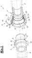
- the figures show a connector 1 for connecting two fluid-carrying elements, in particular for connecting two motor vehicle pipelines 2, 3.
- the connector 1 has a female plug-in part 4 and a male plug-in part 5 that can be plugged into the female plug-in part 4.
- a retainer 6 is connected to the connector 1 according to the invention, with which the male plug-in part 5 can be fixed on the female plug-in part 4.
- the connector 1 shown in the figures is a so-called VDA connector.
- the retainer 6 In the unfixed state of the male plug-in part 5, which is particularly in the Fig. 2 is shown, the retainer 6 is blocked by a verification sleeve 7 provided in the female plug-in part 4.
- the verification sleeve 7 When the male plug-in part 5 is inserted into the female plug-in part 4, the verification sleeve 7 is displaced axially in the insertion direction, so that the retainer 6 is released and the male plug-in part 5 is fixed on the female plug-in part 4.
- FIG Fig. 3 The fully inserted or fixed state of the male plug part 5 on the female plug part 4 is shown in FIG Fig. 3 shown.
- the female plug-in part 4 and the male plug-in part 5 are made from at least one plastic, and the male plug-in part 5 and the female plug-in part 4 preferably consist of polyphenylene sulfide or essentially of polyphenylene sulfide.
- the retainer 6 is preferably made of steel or essentially of steel.
- the female plug-in part 4 has two opposing retaining recesses 8, which are designed as retaining slots. This is especially true in the Fig. 1 to recognize.
- the retaining recesses 8 are in the unfixed state ( Fig. 2 ) of the male plug-in part 5 blocked by the verification sleeve 7. In the fully inserted or fixed state of the male plug-in part 5 ( Fig. 3 ) the retainer 6 reaches through the two retainer recesses 8 or the retainer 6 reaches through the retainer recesses 8 completely in this state.
- the retainer 6 is pretensioned by the verification sleeve 7 in the unfixed state of the male plug-in part 5 and, after the verification sleeve 7 has been axially displaced in the insertion direction, during the process of inserting the male plug-in part 5, it snaps through the two retainer recesses 8 through or completely through.
- the verification sleeve 7 is designed as a one-piece plastic component and is partially or partially hollow-cylindrical and partially or partially frustoconical, so that the verification sleeve 7, as recommended and in the exemplary embodiment, tapers partially or partially in the insertion direction of the male plug-in part 5.
- the verification sleeve 7 is axially displaced in the insertion direction by direct contact of the male plug-in part 5 with the verification sleeve 7, and it is recommended, and in the exemplary embodiment, that the male plug-in part 5 is pushed into the verification sleeve 7 at least in some areas.
- the direct contact between the male plug-in part 5 and the Verification sleeve 7 is provided during the insertion process by means of an inclined surface 9 of the male plug-in part 5, which interacts with a complementary inclined surface 10 of the verification sleeve 7 or engages with it during the insertion process.
- the inclined surface 9 and the complementary inclined surface 10 rise in the axial direction of the male plug-in part or of the verification sleeve 7 counter to the plug-in direction of the male plug-in part 5.
- the axial direction of the male plug-in part 5 means in particular the direction of the longitudinal axis Ls of the male plug-in part 5.
- the axial direction of the verification sleeve 7 means in particular the direction of the longitudinal axis or longitudinal center axis Lv of the verification sleeve 7 that runs through the two sleeve openings.
- the inclined surface 9 and / or the complementary inclined surface 10 rises continuously and step-free and preferably increases by 15 ° to 50 ° with respect to the longitudinal axis of the male plug-in part 5 or the verification sleeve 7.
- the inclined surface 9 and the complementary inclined surface 10 rise by approximately 30 ° counter to the insertion direction of the male plug-in part 5.
- the rise angle is Inclined surface 9 and the complementary inclined surface 10 are identical or essentially identical.
- the inclined surface 9 runs around the entire circumference of the male plug-in part 5.
- the U-shaped retainer 6 is designed with a U-bracket 13 and two U-legs 14 connected to the U-bracket 13.
- the U-legs 14 when the male plug-in part 5 is fully inserted or fixed, the U-legs 14 each pass through a retaining recess 8 of the female plug-in part 4 or each completely penetrate this retaining recess 8.
- the U-legs 14 expediently engage behind the stop flange 11 of the male plug-in part 5 and, in the exemplary embodiment according to the figures, engage in particular in the fixing groove 12 of the male plug-in part 5. In this condition ( Fig. 3 ) the male plug-in part 5 is completely or properly fixed to the female plug-in part 4.
Landscapes
- Engineering & Computer Science (AREA)
- General Engineering & Computer Science (AREA)
- Mechanical Engineering (AREA)
- Quick-Acting Or Multi-Walled Pipe Joints (AREA)
Priority Applications (2)
| Application Number | Priority Date | Filing Date | Title |
|---|---|---|---|
| EP20175716.8A EP3913272B1 (fr) | 2020-05-20 | 2020-05-20 | Dispositif de raccordement permettant de raccorder deux éléments fluides |
| PCT/IB2021/054337 WO2021234606A1 (fr) | 2020-05-20 | 2021-05-19 | Raccord pour relier deux éléments conducteurs de fluide |
Applications Claiming Priority (1)
| Application Number | Priority Date | Filing Date | Title |
|---|---|---|---|
| EP20175716.8A EP3913272B1 (fr) | 2020-05-20 | 2020-05-20 | Dispositif de raccordement permettant de raccorder deux éléments fluides |
Publications (2)
| Publication Number | Publication Date |
|---|---|
| EP3913272A1 true EP3913272A1 (fr) | 2021-11-24 |
| EP3913272B1 EP3913272B1 (fr) | 2023-02-22 |
Family
ID=70802624
Family Applications (1)
| Application Number | Title | Priority Date | Filing Date |
|---|---|---|---|
| EP20175716.8A Active EP3913272B1 (fr) | 2020-05-20 | 2020-05-20 | Dispositif de raccordement permettant de raccorder deux éléments fluides |
Country Status (2)
| Country | Link |
|---|---|
| EP (1) | EP3913272B1 (fr) |
| WO (1) | WO2021234606A1 (fr) |
Cited By (3)
| Publication number | Priority date | Publication date | Assignee | Title |
|---|---|---|---|---|
| EP4194734A1 (fr) * | 2021-12-08 | 2023-06-14 | Veritas Ag | Elément de liaison |
| US12123530B2 (en) * | 2021-10-08 | 2024-10-22 | Hanil Tube Corporation | Coupling assembly with valves |
| US12460757B2 (en) | 2024-02-13 | 2025-11-04 | Hutchinson Fluid Management Systems, Inc. | Quick connector coupling with verification tab |
Citations (3)
| Publication number | Priority date | Publication date | Assignee | Title |
|---|---|---|---|---|
| DE10125499C1 (de) * | 2001-05-23 | 2002-08-14 | Schaefer Stettiner Schrauben | Steckverbindung, insbesondere für Rohrleitungen |
| EP2644957A1 (fr) * | 2012-03-26 | 2013-10-02 | Veritas Ag | Agencement de connecteur à fiches |
| EP3388727A1 (fr) * | 2017-04-13 | 2018-10-17 | Pres-Block S.P.A. | Ensemble de connexion destiné à un système de chauffage et/ou de climatisation |
-
2020
- 2020-05-20 EP EP20175716.8A patent/EP3913272B1/fr active Active
-
2021
- 2021-05-19 WO PCT/IB2021/054337 patent/WO2021234606A1/fr not_active Ceased
Patent Citations (3)
| Publication number | Priority date | Publication date | Assignee | Title |
|---|---|---|---|---|
| DE10125499C1 (de) * | 2001-05-23 | 2002-08-14 | Schaefer Stettiner Schrauben | Steckverbindung, insbesondere für Rohrleitungen |
| EP2644957A1 (fr) * | 2012-03-26 | 2013-10-02 | Veritas Ag | Agencement de connecteur à fiches |
| EP3388727A1 (fr) * | 2017-04-13 | 2018-10-17 | Pres-Block S.P.A. | Ensemble de connexion destiné à un système de chauffage et/ou de climatisation |
Cited By (3)
| Publication number | Priority date | Publication date | Assignee | Title |
|---|---|---|---|---|
| US12123530B2 (en) * | 2021-10-08 | 2024-10-22 | Hanil Tube Corporation | Coupling assembly with valves |
| EP4194734A1 (fr) * | 2021-12-08 | 2023-06-14 | Veritas Ag | Elément de liaison |
| US12460757B2 (en) | 2024-02-13 | 2025-11-04 | Hutchinson Fluid Management Systems, Inc. | Quick connector coupling with verification tab |
Also Published As
| Publication number | Publication date |
|---|---|
| EP3913272B1 (fr) | 2023-02-22 |
| WO2021234606A1 (fr) | 2021-11-25 |
Similar Documents
| Publication | Publication Date | Title |
|---|---|---|
| EP3913271B1 (fr) | Connecteur | |
| DE69520669T2 (de) | Tiefziehbare schnellkupplung | |
| EP3936752A1 (fr) | Dispositif de raccordement permettant de raccorder deux éléments fluides | |
| EP3913272B1 (fr) | Dispositif de raccordement permettant de raccorder deux éléments fluides | |
| DE19653257A1 (de) | Zum Anschluß eines Schlauches mit einem zweiten Bauteil vorgesehene Schlauchkupplung | |
| DE102008013565A1 (de) | Einsteckkupplung | |
| DE102013220702A1 (de) | Spaltoptimierter Sicherungsring für ein mehrreihiges Wälzlager | |
| DE102020006979B4 (de) | Fluidkupplung, insbesondere für Fluid führende Leitungen in Kraftfahrzeugen, Kombination aus der Fluidkupplung mit einem entsprechenden Gegenstück und Verfahren zum Herstellen einer Verbindung von zwei Fluidleitungen | |
| DE19854148A1 (de) | Steckkupplung | |
| DE102011121828A1 (de) | Steckverbindungsanordnung für Fluidleitungen | |
| DE19945721A1 (de) | Steckkupplung | |
| EP2738435A1 (fr) | Agrégat de véhicule automobile et procédé de fabrication d'un agrégat de véhicule automobile | |
| EP1749167B1 (fr) | Procede pour realiser une fiche de connexion | |
| DE19533920A1 (de) | Vorrichtung zum lösbaren Verbinden der Enden eines Verbindungsschlauches mit jeweils einem Bauteil aus Kunststoff | |
| EP1126206B1 (fr) | Raccord de compression pour tuyaux | |
| DE10158208A1 (de) | Steckkupplung | |
| EP0178626B1 (fr) | Manchon d'accouplement pour raccorder deux extrémités de tuyaux | |
| DE102017001396B4 (de) | Schnellverbindungsvorrichtung, Schnellverbindungssystem und Herstellungsverfahren | |
| DE10217197B4 (de) | Lösbare Kupplung zur Verbindung zweier Schlauchenden einer aus wenigstens zwei Schläuchen zusammengesetzen, flüssigkeitsführenden Schlauchleitung | |
| DE3513188A1 (de) | Schlauchkupplung | |
| DE2600621C3 (de) | Gewindelose Verbindung für Rohre und Verfahren zu ihrer Herstellung | |
| DE102011015462B4 (de) | Verfahren zur Herstellung eines Formteils | |
| DE102016116652A1 (de) | Hybridfitting zum Anschluss an ein Ende eines Rohres | |
| DE9114365U1 (de) | Kupplungsmuffe für Kraftstoffleitungen | |
| EP1475562A1 (fr) | Raccord de tuyaux |
Legal Events
| Date | Code | Title | Description |
|---|---|---|---|
| STAA | Information on the status of an ep patent application or granted ep patent |
Free format text: STATUS: EXAMINATION IS IN PROGRESS |
|
| PUAI | Public reference made under article 153(3) epc to a published international application that has entered the european phase |
Free format text: ORIGINAL CODE: 0009012 |
|
| 17P | Request for examination filed |
Effective date: 20201124 |
|
| AK | Designated contracting states |
Kind code of ref document: A1 Designated state(s): AL AT BE BG CH CY CZ DE DK EE ES FI FR GB GR HR HU IE IS IT LI LT LU LV MC MK MT NL NO PL PT RO RS SE SI SK SM TR |
|
| B565 | Issuance of search results under rule 164(2) epc |
Effective date: 20201020 |
|
| GRAP | Despatch of communication of intention to grant a patent |
Free format text: ORIGINAL CODE: EPIDOSNIGR1 |
|
| STAA | Information on the status of an ep patent application or granted ep patent |
Free format text: STATUS: GRANT OF PATENT IS INTENDED |
|
| INTG | Intention to grant announced |
Effective date: 20221021 |
|
| GRAS | Grant fee paid |
Free format text: ORIGINAL CODE: EPIDOSNIGR3 |
|
| GRAA | (expected) grant |
Free format text: ORIGINAL CODE: 0009210 |
|
| STAA | Information on the status of an ep patent application or granted ep patent |
Free format text: STATUS: THE PATENT HAS BEEN GRANTED |
|
| AK | Designated contracting states |
Kind code of ref document: B1 Designated state(s): AL AT BE BG CH CY CZ DE DK EE ES FI FR GB GR HR HU IE IS IT LI LT LU LV MC MK MT NL NO PL PT RO RS SE SI SK SM TR |
|
| REG | Reference to a national code |
Ref country code: GB Ref legal event code: FG4D Free format text: NOT ENGLISH |
|
| REG | Reference to a national code |
Ref country code: CH Ref legal event code: EP |
|
| REG | Reference to a national code |
Ref country code: DE Ref legal event code: R096 Ref document number: 502020002553 Country of ref document: DE |
|
| REG | Reference to a national code |
Ref country code: AT Ref legal event code: REF Ref document number: 1549719 Country of ref document: AT Kind code of ref document: T Effective date: 20230315 Ref country code: IE Ref legal event code: FG4D Free format text: LANGUAGE OF EP DOCUMENT: GERMAN |
|
| REG | Reference to a national code |
Ref country code: LT Ref legal event code: MG9D |
|
| P01 | Opt-out of the competence of the unified patent court (upc) registered |
Effective date: 20230524 |
|
| REG | Reference to a national code |
Ref country code: NL Ref legal event code: MP Effective date: 20230222 |
|
| PG25 | Lapsed in a contracting state [announced via postgrant information from national office to epo] |
Ref country code: RS Free format text: LAPSE BECAUSE OF FAILURE TO SUBMIT A TRANSLATION OF THE DESCRIPTION OR TO PAY THE FEE WITHIN THE PRESCRIBED TIME-LIMIT Effective date: 20230222 Ref country code: PT Free format text: LAPSE BECAUSE OF FAILURE TO SUBMIT A TRANSLATION OF THE DESCRIPTION OR TO PAY THE FEE WITHIN THE PRESCRIBED TIME-LIMIT Effective date: 20230622 Ref country code: NO Free format text: LAPSE BECAUSE OF FAILURE TO SUBMIT A TRANSLATION OF THE DESCRIPTION OR TO PAY THE FEE WITHIN THE PRESCRIBED TIME-LIMIT Effective date: 20230522 Ref country code: NL Free format text: LAPSE BECAUSE OF FAILURE TO SUBMIT A TRANSLATION OF THE DESCRIPTION OR TO PAY THE FEE WITHIN THE PRESCRIBED TIME-LIMIT Effective date: 20230222 Ref country code: LV Free format text: LAPSE BECAUSE OF FAILURE TO SUBMIT A TRANSLATION OF THE DESCRIPTION OR TO PAY THE FEE WITHIN THE PRESCRIBED TIME-LIMIT Effective date: 20230222 Ref country code: LT Free format text: LAPSE BECAUSE OF FAILURE TO SUBMIT A TRANSLATION OF THE DESCRIPTION OR TO PAY THE FEE WITHIN THE PRESCRIBED TIME-LIMIT Effective date: 20230222 Ref country code: HR Free format text: LAPSE BECAUSE OF FAILURE TO SUBMIT A TRANSLATION OF THE DESCRIPTION OR TO PAY THE FEE WITHIN THE PRESCRIBED TIME-LIMIT Effective date: 20230222 Ref country code: ES Free format text: LAPSE BECAUSE OF FAILURE TO SUBMIT A TRANSLATION OF THE DESCRIPTION OR TO PAY THE FEE WITHIN THE PRESCRIBED TIME-LIMIT Effective date: 20230222 |
|
| PG25 | Lapsed in a contracting state [announced via postgrant information from national office to epo] |
Ref country code: SE Free format text: LAPSE BECAUSE OF FAILURE TO SUBMIT A TRANSLATION OF THE DESCRIPTION OR TO PAY THE FEE WITHIN THE PRESCRIBED TIME-LIMIT Effective date: 20230222 Ref country code: PL Free format text: LAPSE BECAUSE OF FAILURE TO SUBMIT A TRANSLATION OF THE DESCRIPTION OR TO PAY THE FEE WITHIN THE PRESCRIBED TIME-LIMIT Effective date: 20230222 Ref country code: IS Free format text: LAPSE BECAUSE OF FAILURE TO SUBMIT A TRANSLATION OF THE DESCRIPTION OR TO PAY THE FEE WITHIN THE PRESCRIBED TIME-LIMIT Effective date: 20230622 Ref country code: GR Free format text: LAPSE BECAUSE OF FAILURE TO SUBMIT A TRANSLATION OF THE DESCRIPTION OR TO PAY THE FEE WITHIN THE PRESCRIBED TIME-LIMIT Effective date: 20230523 Ref country code: FI Free format text: LAPSE BECAUSE OF FAILURE TO SUBMIT A TRANSLATION OF THE DESCRIPTION OR TO PAY THE FEE WITHIN THE PRESCRIBED TIME-LIMIT Effective date: 20230222 |
|
| PG25 | Lapsed in a contracting state [announced via postgrant information from national office to epo] |
Ref country code: SM Free format text: LAPSE BECAUSE OF FAILURE TO SUBMIT A TRANSLATION OF THE DESCRIPTION OR TO PAY THE FEE WITHIN THE PRESCRIBED TIME-LIMIT Effective date: 20230222 Ref country code: RO Free format text: LAPSE BECAUSE OF FAILURE TO SUBMIT A TRANSLATION OF THE DESCRIPTION OR TO PAY THE FEE WITHIN THE PRESCRIBED TIME-LIMIT Effective date: 20230222 Ref country code: EE Free format text: LAPSE BECAUSE OF FAILURE TO SUBMIT A TRANSLATION OF THE DESCRIPTION OR TO PAY THE FEE WITHIN THE PRESCRIBED TIME-LIMIT Effective date: 20230222 Ref country code: DK Free format text: LAPSE BECAUSE OF FAILURE TO SUBMIT A TRANSLATION OF THE DESCRIPTION OR TO PAY THE FEE WITHIN THE PRESCRIBED TIME-LIMIT Effective date: 20230222 Ref country code: CZ Free format text: LAPSE BECAUSE OF FAILURE TO SUBMIT A TRANSLATION OF THE DESCRIPTION OR TO PAY THE FEE WITHIN THE PRESCRIBED TIME-LIMIT Effective date: 20230222 |
|
| REG | Reference to a national code |
Ref country code: DE Ref legal event code: R097 Ref document number: 502020002553 Country of ref document: DE |
|
| PG25 | Lapsed in a contracting state [announced via postgrant information from national office to epo] |
Ref country code: SK Free format text: LAPSE BECAUSE OF FAILURE TO SUBMIT A TRANSLATION OF THE DESCRIPTION OR TO PAY THE FEE WITHIN THE PRESCRIBED TIME-LIMIT Effective date: 20230222 |
|
| PLBE | No opposition filed within time limit |
Free format text: ORIGINAL CODE: 0009261 |
|
| REG | Reference to a national code |
Ref country code: CH Ref legal event code: PL |
|
| STAA | Information on the status of an ep patent application or granted ep patent |
Free format text: STATUS: NO OPPOSITION FILED WITHIN TIME LIMIT |
|
| PG25 | Lapsed in a contracting state [announced via postgrant information from national office to epo] |
Ref country code: MC Free format text: LAPSE BECAUSE OF FAILURE TO SUBMIT A TRANSLATION OF THE DESCRIPTION OR TO PAY THE FEE WITHIN THE PRESCRIBED TIME-LIMIT Effective date: 20230222 |
|
| REG | Reference to a national code |
Ref country code: BE Ref legal event code: MM Effective date: 20230531 |
|
| 26N | No opposition filed |
Effective date: 20231123 |
|
| PG25 | Lapsed in a contracting state [announced via postgrant information from national office to epo] |
Ref country code: SI Free format text: LAPSE BECAUSE OF FAILURE TO SUBMIT A TRANSLATION OF THE DESCRIPTION OR TO PAY THE FEE WITHIN THE PRESCRIBED TIME-LIMIT Effective date: 20230222 Ref country code: MC Free format text: LAPSE BECAUSE OF FAILURE TO SUBMIT A TRANSLATION OF THE DESCRIPTION OR TO PAY THE FEE WITHIN THE PRESCRIBED TIME-LIMIT Effective date: 20230222 Ref country code: LU Free format text: LAPSE BECAUSE OF NON-PAYMENT OF DUE FEES Effective date: 20230520 Ref country code: LI Free format text: LAPSE BECAUSE OF NON-PAYMENT OF DUE FEES Effective date: 20230531 Ref country code: CH Free format text: LAPSE BECAUSE OF NON-PAYMENT OF DUE FEES Effective date: 20230531 |
|
| REG | Reference to a national code |
Ref country code: IE Ref legal event code: MM4A |
|
| PG25 | Lapsed in a contracting state [announced via postgrant information from national office to epo] |
Ref country code: IE Free format text: LAPSE BECAUSE OF NON-PAYMENT OF DUE FEES Effective date: 20230520 |
|
| PG25 | Lapsed in a contracting state [announced via postgrant information from national office to epo] |
Ref country code: IE Free format text: LAPSE BECAUSE OF NON-PAYMENT OF DUE FEES Effective date: 20230520 |
|
| PG25 | Lapsed in a contracting state [announced via postgrant information from national office to epo] |
Ref country code: IT Free format text: LAPSE BECAUSE OF FAILURE TO SUBMIT A TRANSLATION OF THE DESCRIPTION OR TO PAY THE FEE WITHIN THE PRESCRIBED TIME-LIMIT Effective date: 20230222 Ref country code: BE Free format text: LAPSE BECAUSE OF NON-PAYMENT OF DUE FEES Effective date: 20230531 |
|
| PG25 | Lapsed in a contracting state [announced via postgrant information from national office to epo] |
Ref country code: BG Free format text: LAPSE BECAUSE OF FAILURE TO SUBMIT A TRANSLATION OF THE DESCRIPTION OR TO PAY THE FEE WITHIN THE PRESCRIBED TIME-LIMIT Effective date: 20230222 |
|
| PG25 | Lapsed in a contracting state [announced via postgrant information from national office to epo] |
Ref country code: BG Free format text: LAPSE BECAUSE OF FAILURE TO SUBMIT A TRANSLATION OF THE DESCRIPTION OR TO PAY THE FEE WITHIN THE PRESCRIBED TIME-LIMIT Effective date: 20230222 |
|
| GBPC | Gb: european patent ceased through non-payment of renewal fee |
Effective date: 20240520 |
|
| PG25 | Lapsed in a contracting state [announced via postgrant information from national office to epo] |
Ref country code: GB Free format text: LAPSE BECAUSE OF NON-PAYMENT OF DUE FEES Effective date: 20240520 |
|
| PGFP | Annual fee paid to national office [announced via postgrant information from national office to epo] |
Ref country code: DE Payment date: 20250519 Year of fee payment: 6 |
|
| PGFP | Annual fee paid to national office [announced via postgrant information from national office to epo] |
Ref country code: FR Payment date: 20250526 Year of fee payment: 6 |
|
| PGFP | Annual fee paid to national office [announced via postgrant information from national office to epo] |
Ref country code: AT Payment date: 20250721 Year of fee payment: 5 |
|
| PG25 | Lapsed in a contracting state [announced via postgrant information from national office to epo] |
Ref country code: CY Free format text: LAPSE BECAUSE OF FAILURE TO SUBMIT A TRANSLATION OF THE DESCRIPTION OR TO PAY THE FEE WITHIN THE PRESCRIBED TIME-LIMIT; INVALID AB INITIO Effective date: 20200520 |
|
| PG25 | Lapsed in a contracting state [announced via postgrant information from national office to epo] |
Ref country code: HU Free format text: LAPSE BECAUSE OF FAILURE TO SUBMIT A TRANSLATION OF THE DESCRIPTION OR TO PAY THE FEE WITHIN THE PRESCRIBED TIME-LIMIT; INVALID AB INITIO Effective date: 20200520 |
|
| PG25 | Lapsed in a contracting state [announced via postgrant information from national office to epo] |
Ref country code: TR Free format text: LAPSE BECAUSE OF FAILURE TO SUBMIT A TRANSLATION OF THE DESCRIPTION OR TO PAY THE FEE WITHIN THE PRESCRIBED TIME-LIMIT Effective date: 20230222 |