EP3914317B1 - Procédé pour le remplissage d'un filtre à membrane - Google Patents
Procédé pour le remplissage d'un filtre à membrane Download PDFInfo
- Publication number
- EP3914317B1 EP3914317B1 EP20701962.1A EP20701962A EP3914317B1 EP 3914317 B1 EP3914317 B1 EP 3914317B1 EP 20701962 A EP20701962 A EP 20701962A EP 3914317 B1 EP3914317 B1 EP 3914317B1
- Authority
- EP
- European Patent Office
- Prior art keywords
- pressure
- chamber
- membrane filter
- partial circuit
- filling
- Prior art date
- Legal status (The legal status is an assumption and is not a legal conclusion. Google has not performed a legal analysis and makes no representation as to the accuracy of the status listed.)
- Active
Links
Images


Classifications
-
- A—HUMAN NECESSITIES
- A61—MEDICAL OR VETERINARY SCIENCE; HYGIENE
- A61M—DEVICES FOR INTRODUCING MEDIA INTO, OR ONTO, THE BODY; DEVICES FOR TRANSDUCING BODY MEDIA OR FOR TAKING MEDIA FROM THE BODY; DEVICES FOR PRODUCING OR ENDING SLEEP OR STUPOR
- A61M1/00—Suction or pumping devices for medical purposes; Devices for carrying-off, for treatment of, or for carrying-over, body-liquids; Drainage systems
- A61M1/36—Other treatment of blood in a by-pass of the natural circulatory system, e.g. temperature adaptation, irradiation ; Extra-corporeal blood circuits
- A61M1/3621—Extra-corporeal blood circuits
- A61M1/3643—Priming, rinsing before or after use
- A61M1/3644—Mode of operation
- A61M1/3649—Mode of operation using dialysate as priming or rinsing liquid
-
- A—HUMAN NECESSITIES
- A61—MEDICAL OR VETERINARY SCIENCE; HYGIENE
- A61M—DEVICES FOR INTRODUCING MEDIA INTO, OR ONTO, THE BODY; DEVICES FOR TRANSDUCING BODY MEDIA OR FOR TAKING MEDIA FROM THE BODY; DEVICES FOR PRODUCING OR ENDING SLEEP OR STUPOR
- A61M1/00—Suction or pumping devices for medical purposes; Devices for carrying-off, for treatment of, or for carrying-over, body-liquids; Drainage systems
- A61M1/36—Other treatment of blood in a by-pass of the natural circulatory system, e.g. temperature adaptation, irradiation ; Extra-corporeal blood circuits
- A61M1/3621—Extra-corporeal blood circuits
- A61M1/3627—Degassing devices; Buffer reservoirs; Drip chambers; Blood filters
- A61M1/3629—Degassing devices; Buffer reservoirs; Drip chambers; Blood filters degassing by changing pump speed, e.g. during priming
-
- A—HUMAN NECESSITIES
- A61—MEDICAL OR VETERINARY SCIENCE; HYGIENE
- A61M—DEVICES FOR INTRODUCING MEDIA INTO, OR ONTO, THE BODY; DEVICES FOR TRANSDUCING BODY MEDIA OR FOR TAKING MEDIA FROM THE BODY; DEVICES FOR PRODUCING OR ENDING SLEEP OR STUPOR
- A61M1/00—Suction or pumping devices for medical purposes; Devices for carrying-off, for treatment of, or for carrying-over, body-liquids; Drainage systems
- A61M1/36—Other treatment of blood in a by-pass of the natural circulatory system, e.g. temperature adaptation, irradiation ; Extra-corporeal blood circuits
- A61M1/3621—Extra-corporeal blood circuits
- A61M1/3643—Priming, rinsing before or after use
-
- A—HUMAN NECESSITIES
- A61—MEDICAL OR VETERINARY SCIENCE; HYGIENE
- A61M—DEVICES FOR INTRODUCING MEDIA INTO, OR ONTO, THE BODY; DEVICES FOR TRANSDUCING BODY MEDIA OR FOR TAKING MEDIA FROM THE BODY; DEVICES FOR PRODUCING OR ENDING SLEEP OR STUPOR
- A61M1/00—Suction or pumping devices for medical purposes; Devices for carrying-off, for treatment of, or for carrying-over, body-liquids; Drainage systems
- A61M1/36—Other treatment of blood in a by-pass of the natural circulatory system, e.g. temperature adaptation, irradiation ; Extra-corporeal blood circuits
- A61M1/3621—Extra-corporeal blood circuits
- A61M1/3643—Priming, rinsing before or after use
- A61M1/3644—Mode of operation
- A61M1/365—Mode of operation through membranes, e.g. by inverted trans-membrane pressure [TMP]
-
- B—PERFORMING OPERATIONS; TRANSPORTING
- B01—PHYSICAL OR CHEMICAL PROCESSES OR APPARATUS IN GENERAL
- B01D—SEPARATION
- B01D69/00—Semi-permeable membranes for separation processes or apparatus characterised by their form, structure or properties; Manufacturing processes specially adapted therefor
- B01D69/08—Hollow fibre membranes
-
- G—PHYSICS
- G01—MEASURING; TESTING
- G01F—MEASURING VOLUME, VOLUME FLOW, MASS FLOW OR LIQUID LEVEL; METERING BY VOLUME
- G01F1/00—Measuring the volume flow or mass flow of fluid or fluent solid material wherein the fluid passes through a meter in a continuous flow
- G01F1/05—Measuring the volume flow or mass flow of fluid or fluent solid material wherein the fluid passes through a meter in a continuous flow by using mechanical effects
- G01F1/34—Measuring the volume flow or mass flow of fluid or fluent solid material wherein the fluid passes through a meter in a continuous flow by using mechanical effects by measuring pressure or differential pressure
- G01F1/36—Measuring the volume flow or mass flow of fluid or fluent solid material wherein the fluid passes through a meter in a continuous flow by using mechanical effects by measuring pressure or differential pressure the pressure or differential pressure being created by the use of flow constriction
-
- G—PHYSICS
- G01—MEASURING; TESTING
- G01F—MEASURING VOLUME, VOLUME FLOW, MASS FLOW OR LIQUID LEVEL; METERING BY VOLUME
- G01F1/00—Measuring the volume flow or mass flow of fluid or fluent solid material wherein the fluid passes through a meter in a continuous flow
- G01F1/72—Devices for measuring pulsing fluid flows
-
- A—HUMAN NECESSITIES
- A61—MEDICAL OR VETERINARY SCIENCE; HYGIENE
- A61M—DEVICES FOR INTRODUCING MEDIA INTO, OR ONTO, THE BODY; DEVICES FOR TRANSDUCING BODY MEDIA OR FOR TAKING MEDIA FROM THE BODY; DEVICES FOR PRODUCING OR ENDING SLEEP OR STUPOR
- A61M1/00—Suction or pumping devices for medical purposes; Devices for carrying-off, for treatment of, or for carrying-over, body-liquids; Drainage systems
- A61M1/14—Dialysis systems; Artificial kidneys; Blood oxygenators ; Reciprocating systems for treatment of body fluids, e.g. single needle systems for hemofiltration or pheresis
- A61M1/16—Dialysis systems; Artificial kidneys; Blood oxygenators ; Reciprocating systems for treatment of body fluids, e.g. single needle systems for hemofiltration or pheresis with membranes
- A61M1/1621—Constructional aspects thereof
- A61M1/1635—Constructional aspects thereof with volume chamber balancing devices between used and fresh dialysis fluid
-
- A—HUMAN NECESSITIES
- A61—MEDICAL OR VETERINARY SCIENCE; HYGIENE
- A61M—DEVICES FOR INTRODUCING MEDIA INTO, OR ONTO, THE BODY; DEVICES FOR TRANSDUCING BODY MEDIA OR FOR TAKING MEDIA FROM THE BODY; DEVICES FOR PRODUCING OR ENDING SLEEP OR STUPOR
- A61M2205/00—General characteristics of the apparatus
- A61M2205/33—Controlling, regulating or measuring
- A61M2205/3331—Pressure; Flow
-
- A—HUMAN NECESSITIES
- A61—MEDICAL OR VETERINARY SCIENCE; HYGIENE
- A61M—DEVICES FOR INTRODUCING MEDIA INTO, OR ONTO, THE BODY; DEVICES FOR TRANSDUCING BODY MEDIA OR FOR TAKING MEDIA FROM THE BODY; DEVICES FOR PRODUCING OR ENDING SLEEP OR STUPOR
- A61M2205/00—General characteristics of the apparatus
- A61M2205/33—Controlling, regulating or measuring
- A61M2205/3331—Pressure; Flow
- A61M2205/3341—Pressure; Flow stabilising pressure or flow to avoid excessive variation
-
- A—HUMAN NECESSITIES
- A61—MEDICAL OR VETERINARY SCIENCE; HYGIENE
- A61M—DEVICES FOR INTRODUCING MEDIA INTO, OR ONTO, THE BODY; DEVICES FOR TRANSDUCING BODY MEDIA OR FOR TAKING MEDIA FROM THE BODY; DEVICES FOR PRODUCING OR ENDING SLEEP OR STUPOR
- A61M2205/00—General characteristics of the apparatus
- A61M2205/33—Controlling, regulating or measuring
- A61M2205/3331—Pressure; Flow
- A61M2205/3355—Controlling downstream pump pressure
-
- G—PHYSICS
- G01—MEASURING; TESTING
- G01F—MEASURING VOLUME, VOLUME FLOW, MASS FLOW OR LIQUID LEVEL; METERING BY VOLUME
- G01F15/00—Details of, or accessories for, apparatus of groups G01F1/00 - G01F13/00 insofar as such details or appliances are not adapted to particular types of such apparatus
- G01F15/005—Valves
-
- G—PHYSICS
- G01—MEASURING; TESTING
- G01F—MEASURING VOLUME, VOLUME FLOW, MASS FLOW OR LIQUID LEVEL; METERING BY VOLUME
- G01F23/00—Indicating or measuring liquid level or level of fluent solid material, e.g. indicating in terms of volume or indicating by means of an alarm
- G01F23/30—Indicating or measuring liquid level or level of fluent solid material, e.g. indicating in terms of volume or indicating by means of an alarm by floats
-
- G—PHYSICS
- G16—INFORMATION AND COMMUNICATION TECHNOLOGY [ICT] SPECIALLY ADAPTED FOR SPECIFIC APPLICATION FIELDS
- G16H—HEALTHCARE INFORMATICS, i.e. INFORMATION AND COMMUNICATION TECHNOLOGY [ICT] SPECIALLY ADAPTED FOR THE HANDLING OR PROCESSING OF MEDICAL OR HEALTHCARE DATA
- G16H40/00—ICT specially adapted for the management or administration of healthcare resources or facilities; ICT specially adapted for the management or operation of medical equipment or devices
- G16H40/60—ICT specially adapted for the management or administration of healthcare resources or facilities; ICT specially adapted for the management or operation of medical equipment or devices for the operation of medical equipment or devices
- G16H40/63—ICT specially adapted for the management or administration of healthcare resources or facilities; ICT specially adapted for the management or operation of medical equipment or devices for the operation of medical equipment or devices for local operation
Definitions
- the present invention relates to a method for filling a membrane filter of a blood treatment system, wherein the blood treatment system has at least one membrane filter, in particular a hollow fiber membrane filter, with a first and a second chamber, which are semipermeably separated by a membrane, at least one first partial circuit and at least one second partial circuit, wherein the first chamber of the membrane filter is arranged in the first partial circuit and the second chamber of the membrane filter is arranged in the second partial circuit, and wherein the first chamber of the membrane filter is filled with liquid via the first partial circuit, while the second chamber is still filled with air.
- the present invention further comprises a corresponding blood treatment machine and a blood treatment system.
- a filling process is from the DE 10 2011 102 492 A1 known.
- the first chamber of the membrane filter is filled via the first partial circuit in such a way that air is displaced from the first partial circuit into the second partial circuit during at least a partial phase of the filling.
- the DE 10 2015 009 886 A1 further shows a method in which, after filling the first chamber of the membrane filter via the first partial circuit, an overpressure is applied to the first chamber compared to the second chamber.
- DE 100 11 208 C1 show another method for filling a tubing set of a dialysis machine.
- a method according to the preamble of claim 1 is known from US 2014/0217027 A1 known.
- upstream and downstream mean the direction in which the liquids flow through the lines during operation during treatment.
- a blood leak detector can be arranged downstream of the membrane filter. This can be suitable for detecting blood that passes through the membrane from the second subcircuit into the first subcircuit during treatment.
- An air separation chamber can be arranged downstream.
- upstream can refer to the line section in which a blood pump and/or a point of addition for heparin is arranged.
- the object of the present invention is to provide a method and a treatment machine which allow a reliable filling of the membrane filter.
- Embodiments of the present invention are the subject of the subclaims.
- the present invention comprises a method for filling a membrane filter of a blood treatment system, wherein the blood treatment system has at least one blood treatment machine, a membrane filter, in particular a hollow fiber membrane filter, with a first and a second chamber, which are semipermeably separated by a membrane, and at least one first sub-circuit and at least one second sub-circuit, wherein the first chamber of the membrane filter is arranged in the first sub-circuit and the second chamber of the membrane filter is arranged in the second sub-circuit, wherein the first chamber of the membrane filter is filled with liquid via the first sub-circuit, while the second chamber is still filled with air, and wherein a pump is arranged upstream of the membrane filter in the first sub-circuit. It is provided that the control of the pump for filling the first chamber of the membrane filter via the first sub-circuit takes place as a function of a pressure measured in the first sub-circuit and/or the transmembrane pressure.
- the pump By controlling the pump depending on the pressure, an even more reliable filling of the membrane filter is made possible.
- the remaining air islands within the membrane filter can be further reduced.
- the filling state can be detected.
- the first subcircuit is the dialysate circuit and/or the second subcircuit is an extracorporeal bloodstream.
- the present invention therefore relates to the filling of the dialysate chamber of a dialyzer.
- air present in the first chamber is displaced via the membrane into the second chamber of the membrane filter and thus into the second sub-circuit.
- the first chamber of the membrane filter is filled via the first partial circuit from top to bottom.
- the first chamber of the membrane filter is preferably filled via the first partial circuit with the same flow direction in which the blood flows through the membrane filter during blood treatment.
- the two chambers of the membrane filter are filled without an intermediate rotation of the membrane filter.
- the membrane filter is operated in countercurrent during blood treatment in the first and second partial circuits. If the first chamber of the membrane filter is therefore filled from top to bottom via the first partial circuit, in particular in the dialysate circuit, the second chamber of the membrane filter can be filled and/or flushed from bottom to top via the second partial circuit, in particular in the blood circuit, with the same flow direction used during blood treatment, without rotating the membrane filter. This allows the second chamber of the membrane filter to be reliably vented.
- the volume flow generated by the pump and used for filling and/or the time course and/or the duration of the filling by the pump are controlled as a function of a pressure measured in the first and/or second sub-circuit.
- a pressure in the first sub-circuit and/or a transmembrane pressure is measured across the membrane of the membrane filter, the pump being controlled to fill the first chamber of the membrane filter via the first sub-circuit depending on the pressure in the first sub-circuit and/or the transmembrane pressure.
- the pressure upstream and/or downstream of the first chamber in the first sub-circuit can be measured and the first chamber of the membrane filter can be filled via the first sub-circuit depending on this pressure.
- the transmembrane pressure can be determined using a pressure measured by a pressure sensor on the second sub-circuit and a pressure measured by a further pressure sensor on the first sub-circuit.
- the transmembrane pressure can be determined using these two pressure values and a third pressure value measured by a third pressure sensor on the first sub-circuit, whereby the further pressure sensor can be arranged upstream and the third pressure sensor downstream of the membrane filter.
- the determination can be made by calculating the average of the pressures measured by the further pressure sensor and the third pressure sensor and subtracting the pressure in the second sub-circuit from this, or the average can be subtracted from the pressure in the second sub-circuit.
- the present invention is based on the realization that some membrane filters, in particular some dialyzers, are very sensitive to the pressure across the membrane as long as the second chamber is not yet filled with liquid. If in this situation a certain transmembrane pressure is present at the membrane filter for a certain period of time, liquid passes from the first chamber, in particular the dialysate chamber, into the second chamber, in particular the blood chamber, and this can no longer be properly filled later. It must be taken into account that in the dialyzer, where liquid has filled the capillaries, no more air can pass through the capillaries of the fiber wall. Conversely, however, a certain transmembrane pressure is required to effectively displace the air from the first chamber across the membrane into the second chamber.
- the pressure in the first subcircuit and in particular by the pressure upstream of the first chamber can be measured as an alternative to the transmembrane pressure and used or limited for control.
- the filling is controlled such that the pressure in the first sub-circuit and/or the transmembrane pressure does not exceed a first threshold value.
- a delivery rate of the filling is reduced as soon as the pressure in the first partial circuit and/or the transmembrane pressure exceeds a first threshold value.
- the reduction in the filling can also include a complete stopping of the filling.
- a liquid inflow can be reduced and in particular stopped until the pressure in the first partial circuit and/or the transmembrane pressure is again below the first or a second threshold value.
- a delivery rate of the pump is reduced during filling or the pump is stopped as soon as the pressure in the first sub-circuit and/or the transmembrane pressure exceeds a first threshold value, wherein the first threshold value is, for example, at least 50 mBar, for example at least 100 mBar, or for example at least 200 mBar.
- a delivery rate of the pump is increased during filling or the pump is started again as soon as the pressure in the first sub-circuit and/or the transmembrane pressure falls below a second threshold value, wherein the second threshold value is, for example, at least 50 mBar, or, for example, at least 100 mBar, or, for example, at least 150 mBar.
- an absolute value of the first threshold is greater than an absolute value of the second threshold. If the two thresholds are the same, this could result in the pump constantly starting and stopping. This is prevented by using different thresholds.
- the pump is controlled in such a way that an overpressure is created in the first chamber of the membrane filter at least temporarily, in particular a pressure of, for example, at least 50 mbar, or, for example, at least 100 mBar, or, for example, at least 200 mBar.
- the pump for filling the first chamber of the membrane filter is controlled by volume, wherein the volume-controlled control is stopped or the volume flow is reduced as soon as the pressure in the first sub-circuit and/or the transmembrane pressure exceeds a first threshold value, wherein the first threshold value is, for example, at least 50 mBar, or, for example, at least 100 mBar, or, for example, at least 200 mBar.
- the volume-controlled control is resumed or the volume flow is increased as soon as the pressure in the first sub-circuit and/or the transmembrane pressure falls below a second threshold value, wherein the second threshold value is, for example, at least 50 mBar, or, for example, at least 100 mBar, or, for example, at least 150 mBar.
- an absolute value of the first threshold is greater than an absolute value of the second threshold.
- the pressure and flow limitation according to the invention ensures that no air pockets are trapped in the fiber bundle of the membrane filter, which can then no longer be separated. Furthermore, the control according to the invention ensures that sufficient pressure rests on the first chamber in order to displace air located there via the membrane into the second chamber.
- the first chamber of the membrane filter is filled with a pulsatile volume flow, which generates pressure peaks in the first chamber of the membrane filter.
- the pressure peaks and the subsequent pressure drop occur in the rhythm of the pulsatile volume flow.
- the pump preferably works together with a balancing chamber arrangement, which is supplied with liquid by the pump and whose switching leads to a pulsatile volume flow.
- no liquid is drained from the system, at least temporarily, during filling of the first chamber of the membrane filter. This enables faster filling of the first sub-circuit.
- a fluid connection of a secondary air separator arranged downstream of the first chamber in the first partial circuit with the drain can be closed during filling and/or a pump arranged there can not be operated. In particular, this can take place during pressure-controlled filling, in particular during the entire pressure-controlled filling.
- a pump arranged downstream of the membrane filter in the first dialysate circuit is not operated at least temporarily during the filling of the first chamber of the membrane filter.
- a pump arranged downstream of the membrane filter in the first dialysate circuit cannot be operated at least temporarily.
- the pump or pumps can be arranged downstream of a secondary air separator arranged in the first partial circuit.
- the pump or pumps are not operated during the entire pressure-controlled filling.
- the pressure in the second sub-circuit is measured, whereby the filling of the first chamber of the membrane filter takes place via the first sub-circuit and in particular the control of the pump takes place depending on the pressure in the second sub-circuit.
- the measurement of the pressure in the second subcircuit can be part of a measurement of the transmembrane pressure, as already described above.
- the filling of the first chamber of the membrane filter via the first sub-circuit can also be carried out depending on the absolute pressure and/or pressure changes in the second sub-circuit.
- This method is based on the knowledge that the filling level of the first chamber of the membrane filter can be determined by measuring the pressure in the second sub-circuit.
- the present invention makes use of the fact that when air passes from the first chamber through the membrane into the second sub-circuit, the pressure in the second sub-circuit increases.
- dynamic and/or static pressure changes in the second sub-circuit can be recorded and/or monitored.
- the pressure in the second sub-circuit is monitored with regard to pressure changes, in particular pressure fluctuations.
- the timing of the filling of the first chamber depends on the detection of pressure changes, in particular pressure fluctuations, and in particular from a point in time at which pressure changes, in particular pressure fluctuations, are recorded and/or no longer recorded.
- a complete filling of the first chamber of the membrane filter is detected by monitoring for pressure changes, in particular pressure fluctuations, whereby a complete filling is preferably concluded when no more pressure changes, in particular pressure fluctuations, are detected.
- the filling of the first chamber is continued as long as pressure changes, in particular pressure fluctuations, are detected in the second sub-circuit. Furthermore, a minimum residual filling phase can be carried out after no more pressure changes, in particular pressure fluctuations, are detected.
- the filling of the first chamber is continued as long as air is detected in a secondary air separator of the first sub-circuit, wherein a minimum residual filling phase is preferably carried out after no more air is detected.
- the membrane is not permeable to air from the outset due to the material used, or if it has already been completely saturated before the air has been completely displaced from the first chamber of the membrane filter, the air will be displaced via the first sub-circuit into the secondary air separator located downstream of the membrane filter in the first sub-circuit when the first chamber of the membrane filter is (further) filled.
- the secondary air separator By monitoring the secondary air separator, it can therefore be ensured that no more air is pumped from the first chamber of the membrane filter into the first sub-circuit and that the membrane is therefore completely filled even in this configuration.
- the minimum residual filling phase then serves as a safety buffer and for rinsing the membrane filter. This can have a constant length.
- the minimum residual filling phase may comprise a predetermined pumping volume, a predetermined time or a predetermined number of pumping strokes and/or balancing chamber switchings.
- the first chamber of the membrane filter is filled via the first partial circuit with a pulsatile volume flow.
- the pulsatile volume flow can be generated by means of a membrane pump, for example in the form of a balance chamber.
- filling can take place via several balance chamber switches.
- filling can also take place with a constant volume flow.
- the first sub-circuit is filled with a first volume flow of a maximum of 800 ml/min, preferably a maximum of 500 ml/min, at least during a start-up phase of filling the first chamber.
- This limitation can be independent of the measured pressure. After the start-up phase, a larger maximum volume flow can be used, whereby the volume flow can be controlled depending on a measured pressure.
- the second sub-circuit is open to the atmosphere during the filling of the first chamber of the membrane filter via the first sub-circuit, ie it is in fluid communication with the atmosphere.
- the counterpressure generated by the air in the second sub-circuit is reduced and/or eliminated.
- the second sub-circuit is in fluid communication with the atmosphere during the filling of the first chamber of the membrane filter via a component that generates a pressure drop.
- the connection to the atmosphere is preferably made via a filter, in particular a hydrophobic and/or sterile filter and/or a throttle and/or a valve.
- liquid and/or air from the first chamber is displaced via the first partial circuit into a secondary air separator, which is arranged in the first partial circuit downstream of the membrane filter. This improves the filling of the first chamber and the removal of air from the first chamber.
- the secondary air separator is at least temporarily not connected to a fluid outlet of the system, in particular by closing the corresponding fluid connection or not operating a pump. As a result, no fluid flows out of the system, so that filling is accelerated.
- the secondary air separator which is arranged in the first sub-circuit downstream of the membrane filter, is at least temporarily not connected to the atmosphere during the filling of the first chamber of the membrane filter via the first sub-circuit.
- this can lead to a faster increase in the transmembrane pressure up to a desired value and thus to a larger volume flow through the membrane.
- the secondary air separator can have a vessel with an inlet and an outlet, preferably in the lower region, for example in the bottom or in the lower third, of the vessel, so that air collects in the upper region of the vessel and causes a lowering of the liquid level in the vessel.
- the lowering or rising of the level can be detected by the control of the blood treatment device by means of a level sensor.
- a secondary air separator which is arranged in the first sub-circuit downstream of the membrane filter, is continuously connected to the atmosphere via the first sub-circuit while the first chamber of the membrane filter is being filled. This also allows air to be displaced through the first sub-circuit towards the atmosphere.
- the connection to the atmosphere can be provided through an opening in the upper area of the vessel of the secondary air separator.
- the first sub-circuit is filled in a non-balancing manner at least temporarily during the pressure-controlled filling.
- Non-balancing filling means that the same volume of liquid is not added to and removed from the first sub-circuit. As a result, liquid is added to the first sub-circuit overall. With balancing filling, the same volume of liquid is added to and removed from the first sub-circuit. This primarily results in a shift in the liquid in the first sub-circuit and, with this shift in the liquid, also a shift in air, which can then be separated in the secondary air separator.
- the filling of the first chamber of the membrane filter starts via the first partial circuit without a balancing phase.
- the filling of the first chamber of the membrane filter via the first partial circuit takes place without balancing at least until a filling is detected.
- the detection of the filling can take place, for example, using the level sensor of the secondary air separator.
- the filling of the first chamber of the membrane filter via the first partial circuit starts with a balancing phase, which is followed by a non-balancing phase.
- the air from the first chamber is preferably displaced into a secondary air separator arranged downstream of the membrane filter in the first partial circuit.
- Filling the first chamber of the membrane filter is preferably preceded by filling the first sub-circuit. Filling the first chamber of the membrane filter therefore preferably starts from a situation in which the first sub-circuit is otherwise already full.
- the first sub-circuit can be filled in a first step, and the first chamber of the membrane filter can only be filled in a second step.
- the membrane filter can be separated from the first sub-circuit and only fluidically connected to the first sub-circuit for the second step.
- the first sub-circuit is filled without the first chamber of the membrane filter being fluidically connected to the first sub-circuit, and in a second step, the first chamber of the membrane filter is fluidically connected to the first sub-circuit in order to fill it
- the membrane filter can be separated from the first sub-circuit via valves and/or bridged by a bypass line. After After filling the first partial circuit, the valves are opened and/or the bypass line is closed.
- the first step can be carried out without a membrane filter arranged on the blood treatment device, for example it can be carried out at the end of a previous treatment, for example to flush the first sub-circuit.
- the first sub-circuit is then initially already filled with the exception of the membrane filter.
- a short-circuit piece can be inserted into the first sub-circuit instead of the membrane filter or its ends can be connected directly to one another.
- the short-circuit piece is then replaced by the dialyzer and/or the dialyzer is inserted into the first sub-circuit.
- the blood treatment machine is characterized in that the control comprises a filling program which controls the first pump actuator for filling the first chamber of the membrane filter via the first sub-circuit depending on the pressure measured in the first sub-circuit and/or the transmembrane pressure.
- a delivery rate of the pump is reduced during filling or the pump is stopped as soon as the pressure in the first sub-circuit and/or the transmembrane pressure exceeds a first threshold value and the delivery rate of the pump is increased during filling or the pump is started again as soon as the pressure in the first sub-circuit and/or the transmembrane pressure falls below a second threshold value.
- the membrane filter is preferably a disposable one that is coupled to the blood treatment machine to carry out a treatment.
- the second sub-circuit is also preferably a disposable one.
- the first sub-circuit can be a disposable or a fixed component of the blood treatment machine.
- the controller controls one or more pump actuators and/or one or more valve actuators which actuate valves of the first and/or second sub-circuit in order to carry out the filling program.
- the filling program is processed automatically by the controller.
- the controller is programmed to carry out a method as described in more detail above.
- the blood treatment machine according to the invention can in particular be a dialysis machine, in particular for hemodialysis and/or for hemofiltration and/or for hemodiafiltration.
- the present invention further comprises a blood treatment system comprising a blood treatment machine as described above and a membrane filter.
- the blood treatment system preferably further comprises the first and/or the second sub-circuit.
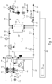
- Fig. 1 shows a schematic, simplified representation of the fluid circuits of an embodiment of a blood treatment system according to the invention.
- the components usually present in the blood treatment system at least those which are required for carrying out the present invention were shown. However, not all components shown and described are absolutely necessary for carrying out the invention. This is clear from the description of the function of the individual components.
- the blood treatment system comprises a membrane filter 1.
- the membrane filter 1 comprises a first chamber 2 and a second chamber 3, which are separated by a semipermeable membrane 50.
- the blood treatment system further comprises a first sub-circuit 4 and a second sub-circuit 5.
- the first chamber 2 of the membrane filter 1 is arranged in the first sub-circuit 4 and the second chamber 3 in the second sub-circuit 5.
- the first chamber 2 of the membrane filter 1 is connected on the inlet side to an inlet line 6 and on the outlet side to an outlet line 7 of the first circuit.
- the membrane filter 1 is a hollow fiber membrane filter which is designed as a dialysis filter.
- the first partial circuit 4 is the dialysate circuit
- the second partial circuit 5 is the extracorporeal blood circuit.
- the blood treatment system further comprises a blood treatment machine 40, shown only schematically here, which comprises at least one first pump actuator of a first pump 10 for pumping liquid in the first partial circuit 4 and at least one second pump actuator of a pump 28 for pumping liquid in the second partial circuit 5.
- the first pump 10 is arranged upstream of the membrane filter 1 in the dialysate circuit.
- a third pump actuator of a third pump 21 and a fourth pump actuator of a fourth pump 20 are provided for pumping liquid in the first sub-circuit 4, both of which are arranged downstream of a secondary air separator 18 in the dialysate circuit.
- pressure sensors 35, 36 are provided for measuring a pressure in the first partial circuit and pressure sensors 34, 33 are provided for measuring the pressure in the second partial circuit.
- the blood treatment machine 40 has a control 41, also shown only schematically, which evaluates the signals from the pressure sensors 33-36 and controls the actuators of the blood treatment machine.
- the membrane filter 1 and the second partial circuit are preferably designed as disposable and can be coupled to the dialysis machine 40 to carry out a treatment.
- the first partial circuit can also be designed as disposable or at least partially or entirely form part of the blood treatment machine 40.
- the first pump 10 in the first partial circuit 4 forms a loading pump, which pumps a liquid, in the exemplary embodiment dialysate, to a balancing chamber arrangement 11 via the line 13. From the balancing chamber arrangement 11, the liquid flows via the line 14, 6 to the inlet of the first chamber 2.
- a sterile filter 15 is provided in the line 14, 6. Furthermore, a further sterile filter 16 is arranged downstream of the sterile filter 15, which forms a second filter stage for the substituate line 17.
- a valve 42 is arranged in the inlet line 6, via which the inflow to the membrane filter 1 can be controlled. Furthermore, downstream of the first chamber 2, a further valve 44 is provided in the outlet line 7.
- the outlet of the first chamber 2 is connected to a secondary air separator 18 via the drain line 7.
- the secondary air separator has a sensor 19, via which air in the secondary air separator can be detected.
- a drain line 45 of the air separator 18 is connected to the balancing chamber arrangement 11 via the third pump 21 designed as a dialysate pump. Used dialysate is pumped into the drain line 23 via the dialysate pump 21 and the balancing chamber arrangement 11.
- an ultrafiltration pump 20 is provided as a fourth pump, which pumps dialysate from the air separator 18 directly to a drain line 22, bypassing the balancing chamber arrangement 11.
- the secondary air separator 18 further comprises a vent valve 43 which connects the air separator 18 to the drain line 22.
- the second sub-circuit has an inlet line 8 which is connected to an inlet of the second chamber 3 of the membrane filter 1, and an outlet line 9 which is connected to the outlet of the second chamber 3.
- the inlet line 8 is part of the arterial line of the extracorporeal blood circuit 5
- the outlet line 9 is part of the venous line of the extracorporeal blood circuit.
- the arterial line comprises a patient-side connector 24, an arterial clamp 26, a heparin pump 27 and a pump hose section which can be inserted into a roller pump 28.
- the venous line has a bubble catcher 29, a bubble detector 38, a venous clamp 37 and a patient-side connector 25.
- a pressure sensor 33 is arranged on the venous bubble trap 29 via a filter 30, for example a hydrophobic filter and/or a sterile filter. Furthermore, the bubble trap is still connected to the atmosphere via the filter 30 and the throttle 32, whereby this connection can be opened and closed by a valve 46.
- An air pump 31 is also provided, by means of which an integrity test of the membrane 50 can be carried out.
- pressure sensors 35 and 36 are provided, via which the pressure upstream and downstream of the first chamber of the membrane filter 1 in the first partial circuit 4 can be measured. Furthermore, a pressure sensor 33 is provided to measure the pressure in the venous line of the second partial circuit, as well as a pressure sensor 34 which measures the arterial pressure upstream of the occluding roller pump 28.
- dialysate is moved in a balancing manner in the first subcircuit 4 by the action of the loading pump 10, the dialysate pump 21 and the balancing chamber arrangement 11.
- the dialysate flows from the balancing chamber arrangement 11 via the sterile filter 15 to the first chamber 2 of the membrane filter 1 and from there via the secondary air separator 19 and the dialysate pump 21 to the balancing chamber arrangement 11.
- the blood is pumped from the arterial connector 24 via the blood pump 28 to the second chamber, flows through this in countercurrent to the dialysate, and flows via the bubble trap 29 to the venous connector 25.
- the first sub-circuit 4, the second sub-circuit 5 and the membrane filter 1 must be filled and optionally rinsed.
- the first sub-circuit 4 is filled with liquid before the membrane filter is filled.
- a liquid is installed between the inlet line 6 and the drain line 7 of the first partial circuit 4, a short-circuit piece 38 is inserted into the first partial circuit instead of the membrane filter 1.
- the first partial circuit 4 is filled with liquid, for example, by actuating the loading pump 10 to fill a balancing chamber of the balancing chamber arrangement with fresh dialysate, which is moved from this balancing chamber into the line 14, for example by displacing liquid that is pumped by means of the dialysate pump 21.
- liquid can also be moved by means of the loading pump 10 from the balancing chamber half of the first balancing chamber 11 that is not fluidically connected to the pump by a valve position into the second balancing chamber half of the second balancing chamber 11' that is not fluidically connected, and liquid can be transferred from the other balancing chamber half of the second balancing chamber 11' into the line 14.
- the still unfilled membrane filter 1 is inserted into the first partial circuit in place of the short-circuit piece 38.
- the second partial circuit 5 is also connected to the membrane filter 5 and, like it, is not yet filled with liquid.
- the first pump 10 is now pressure-controlled for filling the first chamber 2 of the membrane filter 1 with liquid via the first partial circuit 4.
- the pressure in the first and/or second partial circuit is measured and the filling is controlled depending on the measured pressure.
- the filling is preferably controlled by a filling program of the control 41 of the blood treatment machine.
- the central feature of the procedure according to the invention or the control according to the invention is therefore a pressure-controlled filling program for controlling the first pump 10, which is intended to avoid air inclusions in the membrane filter.
- this description refers to controlling, starting and/or stopping the pump 10, this also includes the fact that the pump itself continues to pump, but by opening or closing one or more valves, for example the valves of the balance chambers, a transport of the liquid is influenced, in particular released and/or prevented.
- the filling program preferably controls the filling depending on the transmembrane pressure across the membrane 50 of the membrane filter 1.
- the pressure-controlled filling is continued as long as a change in the venous pressure via the pressure sensor 33, and in particular pressure fluctuations, is observed.
- the blood treatment machine preferentially makes filling switches, ie the loading pump 10 conveys liquid in the first partial circuit 4 in the direction of the membrane filter 1.
- the balancing chamber arrangement 11 has two balancing chambers 11' and 11", which are connected for the filling switchovers via the associated valves 12 in such a way that there is no balancing operation, but rather one balancing chamber drives the other.
- the flow can be limited to a first, low flow rate up to a predetermined switchover, in the exemplary embodiment up to the 6th switchover after attaching the membrane filter 1. In the exemplary embodiment, this is, for example, 500 ml/min.
- the filling pump 10 can, however, be operated with a second, higher flow rate. This is preferably more than 1000 ml/min, e.g. 1200 ml/min.
- the charging pump 10 can operate in a volume-controlled manner.
- the switching is interrupted and/or the flow rate is reduced until the pressure across the membrane has fallen below a second threshold again.
- the second threshold is lower than the first threshold in order to avoid too frequent switching.
- the switching can be interrupted and/or the flow rate reduced if the pressure measured by pressure sensor 35 at the inlet of the first chamber 2 exceeds the venous return pressure measured by pressure sensor 33 by more than 230 mmHg.
- the interruption is maintained until the pressure difference to the venous pressure falls below 200 mmHg again. Only then does the normal filling operation resume. This limits the pressure difference across the membrane.
- the switching of the balancing chamber can be interrupted, for example, by closing the fresh water valve 60 arranged between the charging pump 10 and the balancing chamber arrangement 11.
- the valve 43 can be open so that a second flow path is available for discharging the air from the first chamber 2, or the valve 43 can be closed. With a closed valve, the pressure difference across the membrane required to build up a pressure difference to displace air across the membrane is reached more quickly. This can accelerate the filling of large membrane filters in particular.
- a variation in the venous pressure which is measured, for example, via the pressure sensor 33, is a sign of air separation via the membrane 50 of the membrane filter 1 from the first chamber 2 into the second chamber 3.
- Air in the secondary air separator 18 is a sign that air is being displaced from the first chamber 2 into the drain line 7.
- the membrane filter is considered to be completely filled.
- the filling program still requires a minimum number of switchovers via the dialyzer after a complete filling has been detected.
- the minimum number of switchovers is preferably carried out without pressure control. If air is detected again during this time, it is separated via valve 43 on the secondary air separator.
- the membrane filter is filled with normal, ie balancing chamber switchings, until air has been detected in the secondary air separator 18 for such a long time that it must be assumed that the air separator is running empty (max. 3 switchings with air detected by sensor 19, for example).
- this first step can also be omitted.
- the device then makes filling switches, i.e. non-balancing switches, in the pressure-controlled filling program according to the invention, i.e. the charging pump 10 conveys in the direction of the membrane filter 1.
- the flow is limited, for example, to 500 ml/min.
- the charging pump pumps fluid towards the membrane filter at full or reduced power.
- the resulting pressure peaks on the membrane are initially limited by the compliance in the system and the flow resistance.
- the overpressure generated on the dialyzer membrane between the first chamber and the second chamber ensures that air passes through the membrane 50 into the second chamber and from there escapes into the environment via the ventilation 32. This works as long as the dialyzer membrane is still unwetted at the points where the air bubbles are located and is therefore permeable to air.
- valve 43 is continuously open. Air and liquid from the first chamber 2 of the membrane filter 1 can thus also reach the drain via this route. How much air escapes via which route depends on the flow resistance of the membrane, the hydraulics and the ventilation in the second sub-circuit.
- valve 43 can also be closed as long as there is no significant dialysate outlet pressure, which could accelerate the filling process, especially with very large filters.
- the pressure-controlled filling program As long as the pressure-controlled filling program is running, the course of the venous pressure is monitored. As long as a variation in the venous pressure or air is observed at sensor 19, the device remains in the pressure-controlled filling program, as in the previous step. A variation in the venous pressure is a sign that air is still being moved across the membrane.
- the above monitoring ensures that the membrane is completely wetted at the end of this step (or, if the membrane is not permeable to air, for example, no more air escapes via the dialysate outlet), i.e. the membrane filter is filled as best as possible (without rotation).
- Fig. 2 shows the course of the mean dialysate pressure in a method according to the present invention, ie with pressure control, as line 71 in comparison to the course of the mean dialysate pressure in a method according to the prior art, ie without pressure control, which is shown as line 70.
- the mean dialysate pressure is calculated as the mean value of the pressure at the inlet of chamber 1 (pressure sensor 35) and at the outlet of chamber 1 (pressure sensor 36).
- balancing filling phase 74 which is used in both methods, there is no significant dialysate pressure, since the liquid or air is only displaced in the first partial circuit. According to the present invention, however, this balancing filling phase 74 can also be dispensed with in an alternative embodiment.
- the maximum dialysate pressure initially reached increases with each balancing chamber switchover.
- the pressure peaks do not yet reach the first threshold value 77, so that the pressure control does not intervene.
- the dialysate pressure is therefore limited solely by the compliance of the tubing set, as was already known in the state of the art.
- the pressure peaks exceed the first threshold value 77. If this is detected by the control system, it stops the inflow of dialysate until the transmembrane pressure and/or dialysate pressure is again below a second, lower threshold value 78. Normal filling is then resumed until the first threshold value is exceeded again. In the exemplary embodiment, several pressure peaks therefore occur per balance chamber switchover.
- a flushing phase 76 follows, in which the pressure drops again.
- Fig. 3 now shows in detail the pressure curves at the individual pressure sensors during the filling phases just described according to the present invention.
- the individual lines show the following: 80 Pressure at pressure sensor 35 (pressure at the inlet of the first chamber 2) 81 Pressure at pressure sensor 36 (pressure at the outlet of the first chamber 2) 82 Pressure at pressure sensor 33 (pressure in the venous line/second chamber 3) 83 transmembrane pressure 84 filling level of the first chamber
- the pressure 82 in the venous line or the second chamber 3 fluctuates at the beginning of the pressure-controlled filling phase 75 due to the air displaced from the first chamber to the second chamber via the membrane in time with the balance chamber switching. After a certain number of balance chamber switchings, however, these pressure fluctuations disappear again because the membrane is now wet and no more air can be displaced via the membrane. This also causes the dialysate pressure 81 downstream of the first chamber to rise.
- the pressure 82 on the blood side can be used to detect the complete filling of the membrane filter or the complete saturation of the membrane and/or to control the timing and/or the duration of the filling program, as described in more detail above.
- the detection of the end of the pressure fluctuations of the pressure 82 is followed by a minimum residual filling phase in which the first chamber is further filled.
- the transmembrane pressure is limited by the pressure-controlled filling program to a value of, for example, 200 or 250 mbar. This prevents dialysate from passing into the second chamber, particularly in the minimum residual filling phase, in which high transmembrane pressures would occur without such a pressure limitation.
- the pressure-controlled filling program works directly with the transmembrane pressure, which is compared with a threshold value.
- the average dialysate pressure and/or the pressure at the inlet of the first chamber could also be compared with the threshold value and limited, since the pressure on the dialysate side and in particular the pressure at the inlet of the first chamber is already considerably greater than the pressure on the blood side and therefore strongly determines the transmembrane pressure.
- the second chamber can be filled according to one of the methods known from the prior art.
- the filling can be carried out, for example, by liquid passing over the membrane 50 and/or through the substituate line.
Landscapes
- Health & Medical Sciences (AREA)
- Heart & Thoracic Surgery (AREA)
- Vascular Medicine (AREA)
- General Health & Medical Sciences (AREA)
- Veterinary Medicine (AREA)
- Anesthesiology (AREA)
- Biomedical Technology (AREA)
- Hematology (AREA)
- Life Sciences & Earth Sciences (AREA)
- Animal Behavior & Ethology (AREA)
- Cardiology (AREA)
- Public Health (AREA)
- Engineering & Computer Science (AREA)
- Physics & Mathematics (AREA)
- Fluid Mechanics (AREA)
- General Physics & Mathematics (AREA)
- Chemical & Material Sciences (AREA)
- Chemical Kinetics & Catalysis (AREA)
- External Artificial Organs (AREA)
- Separation Using Semi-Permeable Membranes (AREA)
Claims (15)
- Procédé de remplissage d'un filtre à membrane (1) d'un système de traitement du sang, le système de traitement du sang présentant au moins une machine de traitement du sang (40), un filtre à membrane (1), notamment un filtre à membrane à fibres creuses, avec une première et une deuxième chambre (2, 3), qui sont séparées de manière semi-perméable par une membrane (50), et au moins un premier circuit partiel (4) et au moins un deuxième circuit partiel (5), la première chambre (2) du filtre à membrane (1) étant agencée dans le premier circuit partiel (4) et la deuxième chambre (3) du filtre à membrane (1) dans le deuxième circuit partiel (5), le remplissage de la première chambre (2) du filtre à membrane avec du liquide s'effectuant par l'intermédiaire du premier circuit partiel (4), tandis que la deuxième chambre (3) est encore remplie d'air, le premier circuit partiel (4) étant de préférence un circuit de dialysat et/ou le deuxième circuit partiel (5) étant un circuit sanguin extracorporel, et une pompe (10) étant agencée en amont du filtre à membrane (1) dans le premier circuit partiel (4),la commande de la pompe (10) pour le remplissage de la première chambre (2) du filtre à membrane (1) par l'intermédiaire du premier circuit partiel (4) s'effectuant en fonction d'une pression mesurée dans le premier circuit partiel (4) et/ou d'une pression transmembranaire, et un débit de la pompe (10) étant réduit lors du remplissage ou la pompe (10) étant arrêtée dès que la pression dans le premier circuit partiel (4) et/ou la pression transmembranaire dépasse une première valeur seuil,caractérisé en ce quele débit de la pompe (10) est augmenté lors du remplissage ou la pompe (10) est redémarrée dès que la pression dans le premier circuit partiel (4) et/ou la pression transmembranaire passe en dessous d'une deuxième valeur seuil.
- Procédé selon la revendication 1, le débit volumique utilisé pour le remplissage, généré par la pompe (10), et/ou l'évolution temporelle et/ou la durée du remplissage étant commandés par la pompe (10) en fonction de la pression mesurée dans le premier et/ou le deuxième circuit partiel (4, 5).
- Procédé selon la revendication 1 ou 2, une pression dans le premier circuit partiel (4) et/ou une pression transmembranaire étant déterminée par l'intermédiaire de la membrane (50) du filtre à membrane (1) et la commande de la pompe (10) pour le remplissage de la première chambre (2) du filtre à membrane (10) par l'intermédiaire du premier circuit partiel (4) étant effectuée en fonction de la pression dans le premier circuit partiel (4) et/ou de la pression transmembranaire.
- Procédé selon l'une quelconque des revendications précédentes, la première valeur seuil étant notamment d'au moins 50 mbar, ou notamment d'au moins 100 mbar, ou notamment d'au moins 200 mbar, et/ou la deuxième valeur seuil étant notamment d'au moins 50 mbar, ou notamment d'au moins 100 mbar, ou notamment d'au moins 150 mbar, et/ou une valeur absolue de la première valeur seuil étant supérieure à une valeur absolue de la deuxième valeur seuil, et/ou la pompe (10) étant commandée de telle sorte qu'une surpression se forme au moins temporairement dans la première chambre (4) du filtre à membrane (1), notamment une pression d'au moins 50 mbar, ou notamment d'au moins 100 mbar, ou notamment d'au moins 200 mbar.
- Procédé selon l'une quelconque des revendications précédentes, la pompe (10) pour le remplissage de la première chambre (2) du filtre à membrane (1) étant commandée en volume, la commande en volume étant arrêtée ou le débit volumique étant réduit dès que la pression dans le premier circuit partiel (4) et/ou la pression transmembranaire dépasse une première valeur seuil, la première valeur seuil étant notamment d'au moins 50 mbar, ou notamment d'au moins 100 mbar, ou notamment d'au moins 200 mbar, et/ou la commande en volume étant reprise ou le débit volumique étant augmenté dès que la pression dans le premier circuit partiel (4) et/ou la pression transmembranaire passe en dessous d'une deuxième valeur seuil, la deuxième valeur seuil étant notamment d'au moins 50 mbar, ou notamment d'au moins 100 mbar, ou notamment d'au moins 150 mbar.
- Procédé selon l'une quelconque des revendications précédentes, la première chambre (2) du filtre à membrane (1) étant remplie avec un débit volumique pulsatoire qui génère des pics de pression dans la première chambre (2) du filtre à membrane (1), la pompe coopérant de préférence avec un agencement de chambre d'équilibrage (11) qui est alimenté en liquide par la pompe (10) et dont les commutations conduisent à un débit volumique pulsatoire.
- Procédé selon l'une quelconque des revendications précédentes, aucun liquide n'étant évacué du système au moins temporairement pendant le remplissage de la première chambre (2) du filtre à membrane (1), notamment pendant le remplissage commandé par la pression, et/ou une pompe (20, 21) agencée en aval du filtre à membrane (1) dans le premier circuit de dialysat ne fonctionnant pas au moins temporairement pendant le remplissage de la première chambre (2) du filtre à membrane (1).
- Procédé selon l'une quelconque des revendications précédentes, une pression étant mesurée dans le deuxième circuit partiel (5) et le remplissage de la première chambre (2) du filtre à membrane (1) étant effectué par l'intermédiaire du premier circuit partiel (2) en fonction de la pression dans le deuxième circuit partiel (5), des variations de pression dynamiques et/ou statiques dans le deuxième circuit partiel (5) étant de préférence détectées et/ou surveillées.
- Procédé selon la revendication 8, la pression dans le deuxième circuit partiel (5) étant surveillée en ce qui concerne les variations de pression, notamment les fluctuations de pression, le déroulement temporel du remplissage dépendant de préférence d'une détection des variations de pression, notamment des fluctuations de pression, et/ou le remplissage complet de la première chambre (2) du filtre à membrane (1) étant de préférence détecté par la surveillance des variations de pression, notamment des fluctuations de pression, à un remplissage complet étant de préférence constaté lorsqu'on ne détecte plus de variations de pression, notamment de fluctuations de pression.
- Procédé selon l'une quelconque des revendications précédentes, le remplissage se poursuivant tant que des variations de pression, notamment des fluctuations de pression dans le deuxième circuit partiel (5) et/ou de l'air dans un séparateur d'air secondaire (18) du premier circuit partiel (4) sont détectés, une phase de remplissage restante minimale étant de préférence encore réalisée après qu'aucune variation de pression, notamment fluctuation de pression et/ou qu'aucun air n'est plus détecté, la phase de remplissage restante minimale comprenant de préférence un volume de pompage prédéterminé, un temps prédéterminé ou un nombre prédéterminé de coups de pompe et/ou de commutations de chambre d'équilibrage.
- Procédé selon l'une quelconque des revendications précédentes, le deuxième circuit partiel (4) étant en communication fluidique avec l'atmosphère pendant le remplissage de la première chambre (2) du filtre à membrane (1) par l'intermédiaire du premier circuit partiel (4), le deuxième circuit partiel (3) étant de préférence en communication fluidique avec l'atmosphère pendant le remplissage de la première chambre (2) du filtre à membrane (1) par l'intermédiaire d'un composant générant une chute de pression, notamment par l'intermédiaire d'un filtre (30) et/ou d'un étranglement et/ou d'une vanne (46, 32).
- Procédé selon l'une quelconque des revendications précédentes, du liquide et/ou de l'air étant déplacé hors de la première chambre (2) pendant le remplissage de la première chambre (2) du filtre à membrane (1) par l'intermédiaire du premier circuit partiel (4) dans un séparateur d'air secondaire (18) qui est agencé dans le premier circuit partiel (4) en aval du filtre à membrane (1), le séparateur d'air secondaire (18) n'étant de préférence pas en communication au moins temporairement avec une sortie de liquide du système.
- Procédé selon l'une quelconque des revendications précédentes, le premier circuit partiel (4) étant rempli au moins temporairement de manière non équilibrante pendant le remplissage commandé par la pression, notamment le remplissage de la première chambre (2) du filtre à membrane (1) par l'intermédiaire du premier circuit partiel (4) démarrant sans une phase équilibrante et/ou s'effectuant de manière non équilibrante au moins jusqu'à la détection d'un remplissage.
- Machine de traitement du sang (40), à laquelle peut être couplé au moins un filtre à membrane (1), notamment un filtre à membrane à fibres creuses, avec une première et une deuxième chambre (2, 3), qui sont séparées de manière semi-perméable par une membrane (50), la machine de traitement du sang (40) comprenant :- au moins un premier actionneur de pompage d'une première pompe (10) pour pomper du liquide dans un premier circuit partiel (4), et au moins un deuxième actionneur de pompage d'une deuxième pompe (28) pour pomper du liquide dans un deuxième circuit partiel (5), la première chambre (2) du filtre à membrane (1) étant agencée dans le premier circuit partiel (4) et la deuxième chambre (3) du filtre à membrane (1) étant agencée dans le deuxième circuit partiel (5), la première pompe (10) étant agencée en amont du filtre à membrane (1) dans le premier circuit partiel (4),- au moins deux capteurs de pression (34 - 36) pour mesurer une pression dans le premier et le deuxième circuit partiel (4, 5), et- une commande (41) qui évalue les signaux des capteurs de pression (34 - 36) et qui commande des actionneurs de la machine de traitement du sang (40), la commande (41) comprenant un programme de remplissage, qui procède à une commande du premier actionneur de pompe (35, 36) pour le remplissage de la première chambre (2) du filtre à membrane (1) par l'intermédiaire du premier circuit partiel (4) en fonction de la pression mesurée dans le premier circuit partiel (4) et/ou d'une pression transmembranaire, un débit de la pompe (10) étant réduit lors du remplissage ou la pompe (10) étant arrêtée dès que la pression dans le premier circuit partiel (4) et/ou la pression transmembranaire dépasse une première valeur seuil,caractérisée en ce que
le débit de la pompe (10) est augmenté lors du remplissage ou la pompe (10) est redémarrée dès que la pression dans le premier circuit partiel (4) et/ou la pression transmembranaire passe en dessous d'une deuxième valeur seuil. - Machine de traitement du sang selon la revendication 14, la commande (41) commandant pour l'exécution du programme de remplissage un ou plusieurs actionneurs de pompe et/ou un ou plusieurs actionneurs de soupape qui actionnent des soupapes du premier et/ou du deuxième circuit partiel (4, 5), et/ou la réalisation du programme de remplissage étant effectuée automatiquement par la commande (41), et/ou la commande (41) étant programmée pour exécuter un procédé selon l'une quelconque des revendications 1 à 13.
Applications Claiming Priority (2)
| Application Number | Priority Date | Filing Date | Title |
|---|---|---|---|
| DE102019101542.1A DE102019101542A1 (de) | 2019-01-22 | 2019-01-22 | Verfahren zum Befüllen eines Membranfilters |
| PCT/EP2020/051487 WO2020152209A1 (fr) | 2019-01-22 | 2020-01-22 | Procédé pour le remplissage d'un filtre à membrane |
Publications (2)
| Publication Number | Publication Date |
|---|---|
| EP3914317A1 EP3914317A1 (fr) | 2021-12-01 |
| EP3914317B1 true EP3914317B1 (fr) | 2024-11-06 |
Family
ID=69192057
Family Applications (1)
| Application Number | Title | Priority Date | Filing Date |
|---|---|---|---|
| EP20701962.1A Active EP3914317B1 (fr) | 2019-01-22 | 2020-01-22 | Procédé pour le remplissage d'un filtre à membrane |
Country Status (6)
| Country | Link |
|---|---|
| US (1) | US20220105252A1 (fr) |
| EP (1) | EP3914317B1 (fr) |
| JP (1) | JP7621954B2 (fr) |
| CN (1) | CN113329775B (fr) |
| DE (1) | DE102019101542A1 (fr) |
| WO (1) | WO2020152209A1 (fr) |
Families Citing this family (3)
| Publication number | Priority date | Publication date | Assignee | Title |
|---|---|---|---|---|
| ES2884853T3 (es) * | 2019-08-19 | 2021-12-13 | Gambro Lundia Ab | Método de cebado de un circuito de sangre extracorpóreo de un aparato para el tratamiento de sangre extracorpóreo y aparato para el tratamiento de sangre extracorpóreo |
| DE102020125291A1 (de) | 2020-09-28 | 2022-03-31 | B.Braun Avitum Ag | Automatisches Primen einer extrakorporalen Blutbehandlungsvorrichtung unter Verwendung eines Push-Pull-Verfahrens |
| WO2023150187A2 (fr) * | 2022-02-02 | 2023-08-10 | Zoll Circulation, Inc. | Systèmes et procédés d'amorçage bidirectionnel automatique d'un système d'enrichissement en gaz |
Family Cites Families (23)
| Publication number | Priority date | Publication date | Assignee | Title |
|---|---|---|---|---|
| US4209391A (en) * | 1978-11-06 | 1980-06-24 | Cordis Dow Corp. | Apparatus and method for automatically controlling hemodialysis at a pre-selected ultrafiltration rate |
| DE10011208C1 (de) * | 2000-03-08 | 2001-09-27 | Fresenius Medical Care De Gmbh | Befüllen und/oder Spülen eines extrakorporalen Kreislaufs eines Hämodialyse- und/oder Hämofiltrationsgerätes und Blutschlauchset hierfür |
| ITBO20010354A1 (it) * | 2001-06-05 | 2002-12-05 | Gambro Dasco Spa | Metodo di riempimento e di lavaggio di un filtro di una macchina di dialisi |
| JP4457235B2 (ja) * | 2001-12-18 | 2010-04-28 | 株式会社北九州バイオフィジックス研究所 | 自動血液透析装置および該装置を使用したプライミング方法。 |
| US7975491B2 (en) * | 2005-03-17 | 2011-07-12 | Smisson-Cartledge Biomedical Llc | Heat exchange system for a pump device |
| KR101098125B1 (ko) * | 2005-07-01 | 2011-12-26 | 감브로 룬디아 아베 | 필터 테스트 장치 및 방법 |
| WO2007031809A1 (fr) * | 2005-09-15 | 2007-03-22 | Gambro Lundia Ab | Processus et appareil pour remplir et/ou rincer un circuit sanguin extracorporel |
| JP4783228B2 (ja) | 2006-07-10 | 2011-09-28 | 東レ・メディカル株式会社 | 血液透析装置のプライミング方法および装置 |
| ES2402306T3 (es) | 2007-04-12 | 2013-04-30 | Gambro Lundia Ab | Método y aparato para cebar un circuito de sangre extracorporal |
| US8123947B2 (en) * | 2007-10-22 | 2012-02-28 | Baxter International Inc. | Priming and air removal systems and methods for dialysis |
| DE102011102492A1 (de) | 2011-05-24 | 2012-11-29 | Fresenius Medical Care Deutschland Gmbh | Verfahren zum Spülen und/oder zum Befüllen einer Blutbehandlungsvorrichtung sowie Blutbehandlungsvorrichtung |
| EP2583702B1 (fr) * | 2011-10-20 | 2015-09-02 | D_MED Consulting AG | Procédé destiné à terminer une hémodialyse |
| ES2534477T5 (es) * | 2012-05-09 | 2018-07-20 | D_Med Consulting Ag | Procedimiento para la cebadura de un dispositivo de hemodiálisis |
| US9623164B2 (en) * | 2013-02-01 | 2017-04-18 | Medtronic, Inc. | Systems and methods for multifunctional volumetric fluid control |
| DE102014109136A1 (de) * | 2014-06-30 | 2015-12-31 | Fresenius Medical Care Deutschland Gmbh | Verfahren zum Entfernen von Fluid aus einem Blutfilter nach Beendigung einer Blutbehandlungssitzung mittels Flusserhöhung und Behandlungsvorrichtung zum Durchführen desselben |
| EP3310407B1 (fr) * | 2015-06-19 | 2020-04-08 | Mallinckrodt Hospital Products IP Limited | Dispositifs, procédés et systèmes d'amorçage, de séparation et de collecte de composants sanguins |
| DE102015009886A1 (de) | 2015-07-29 | 2017-02-02 | Fresenius Medical Care Deutschland Gmbh | Verfahren zur Entlüftung eines Dialysators |
| WO2017091449A1 (fr) * | 2015-11-23 | 2017-06-01 | Cardio-Myogen, LLC | Systèmes et procédés de régulation de volume avec régulation de pression pendant des procédures de pontage et perfusion cardiopulmonaire |
| DE102015016842A1 (de) * | 2015-12-23 | 2017-06-29 | Fresenius Medical Care Deutschland Gmbh | Verfahren und Vorrichtung zur Überprüfung eines Dialysators auf das Vorhandensein eines Lecks |
| CN106730086A (zh) * | 2016-12-30 | 2017-05-31 | 北京迈淩医疗技术发展有限公司 | 能够自动调节置换液速率的血液透析滤过装置及其血液透析滤过控制机构 |
| DE102017000227A1 (de) * | 2017-01-13 | 2018-07-19 | Fresenius Medical Care Deutschland Gmbh | Extrakorporale Blutbehandlungsvorrichtung und Verfahren zur Überwachung der Integrität eines Dialysators einer extrakorporalen Blutbehandlungsvorrichtung |
| JP2020521559A (ja) * | 2017-05-26 | 2020-07-27 | バイエル・ヘルスケア・エルエルシーBayer HealthCare LLC | 血行動態監視を伴う注入器状態ロジック |
| JP6462077B1 (ja) * | 2017-09-07 | 2019-01-30 | 日機装株式会社 | 血液浄化装置及びその気泡の排出方法 |
-
2019
- 2019-01-22 DE DE102019101542.1A patent/DE102019101542A1/de active Pending
-
2020
- 2020-01-22 JP JP2021542431A patent/JP7621954B2/ja active Active
- 2020-01-22 EP EP20701962.1A patent/EP3914317B1/fr active Active
- 2020-01-22 CN CN202080010042.7A patent/CN113329775B/zh active Active
- 2020-01-22 WO PCT/EP2020/051487 patent/WO2020152209A1/fr not_active Ceased
- 2020-01-22 US US17/424,598 patent/US20220105252A1/en active Pending
Also Published As
| Publication number | Publication date |
|---|---|
| CN113329775B (zh) | 2025-02-25 |
| WO2020152209A1 (fr) | 2020-07-30 |
| EP3914317A1 (fr) | 2021-12-01 |
| CN113329775A (zh) | 2021-08-31 |
| JP7621954B2 (ja) | 2025-01-27 |
| US20220105252A1 (en) | 2022-04-07 |
| JP2022518766A (ja) | 2022-03-16 |
| DE102019101542A1 (de) | 2020-07-23 |
Similar Documents
| Publication | Publication Date | Title |
|---|---|---|
| EP2714126B1 (fr) | Procédé de rinçage et/ou de remplissage d'un dispositif de traitement du sang et dispositif de traitement du sang | |
| EP2059279B1 (fr) | Appareil de traitement sanguin et procédé pour purger un jeu de lignes à sang d'un appareil de traitement sanguin | |
| DE102006012087B4 (de) | Verfahren zum zumindest teilweise Entleeren eines extrakorporalen Blutkreislaufs und Hämodialysegerät zur Anwendung des Verfahrens | |
| EP2334350B1 (fr) | Dispositif pour remplir un filtre et procédé associé | |
| EP2662101B2 (fr) | Procédé de préremplissage d'un appareil d'hémodialyse | |
| EP0720856A2 (fr) | Dispositif de nettoyage et remplissage en ligne d'un circuit extracorporel sanguin d'une machine de dialyse | |
| DE102007026010A1 (de) | Vorrichtung zur Steuerung einer Einrichtung zum Fördern von Blut, Verfahren zum Fördern von Blut in einer Blutleitung eines extrakorporalen Blutkreislaufs einer extrakorporalen Blutbehandlungsvorrichtung | |
| EP3177338B1 (fr) | Procédé d'élimination par lavage de bulles de gaz d'au moins une zone cible d'un circuit de sang extracorporel | |
| DE102005022545B4 (de) | Verfahren zum luftfreien Füllen der Blutseite einer Hämodialysevorrichtung mit einer physiologischen Elektrolytlösung | |
| EP3445418B1 (fr) | Dispositif thérapeutique médical et procédé pour la surveillance d'un dispositif thérapeutique médical | |
| EP2736561B1 (fr) | Procédé et dispositifs pour détacher des amas gazeux d'un piège à caillots d'une circulation sanguine extra-corporelle | |
| EP0161686B1 (fr) | Procédé de remplissage de la tuyauterie sanguine d'un dispositif d'hémodialyse avec une solution saline | |
| EP3914317A1 (fr) | Procédé pour le remplissage d'un filtre à membrane | |
| EP3177339B1 (fr) | Procédé de lavage d'un circuit de sang extracorporel | |
| EP4069330B1 (fr) | Amorçage automatique d'un dispositif de traitement sanguin extracorporel à l'aide d'un procédé de poussée-traction | |
| WO2018002162A1 (fr) | Unité de commande pour détecter du sang dans une ligne d'évacuation du liquide de dialyse d'un dispositif de traitement du sang et dispositif de traitement du sang | |
| WO2020178301A1 (fr) | Ensemble de conduites sanguines extracorporelles et machine de traitement du sang | |
| EP4565292A1 (fr) | Dispositif de traitement sanguin |
Legal Events
| Date | Code | Title | Description |
|---|---|---|---|
| STAA | Information on the status of an ep patent application or granted ep patent |
Free format text: STATUS: UNKNOWN |
|
| STAA | Information on the status of an ep patent application or granted ep patent |
Free format text: STATUS: THE INTERNATIONAL PUBLICATION HAS BEEN MADE |
|
| PUAI | Public reference made under article 153(3) epc to a published international application that has entered the european phase |
Free format text: ORIGINAL CODE: 0009012 |
|
| STAA | Information on the status of an ep patent application or granted ep patent |
Free format text: STATUS: REQUEST FOR EXAMINATION WAS MADE |
|
| 17P | Request for examination filed |
Effective date: 20210820 |
|
| AK | Designated contracting states |
Kind code of ref document: A1 Designated state(s): AL AT BE BG CH CY CZ DE DK EE ES FI FR GB GR HR HU IE IS IT LI LT LU LV MC MK MT NL NO PL PT RO RS SE SI SK SM TR |
|
| DAV | Request for validation of the european patent (deleted) | ||
| DAX | Request for extension of the european patent (deleted) | ||
| GRAP | Despatch of communication of intention to grant a patent |
Free format text: ORIGINAL CODE: EPIDOSNIGR1 |
|
| STAA | Information on the status of an ep patent application or granted ep patent |
Free format text: STATUS: GRANT OF PATENT IS INTENDED |
|
| RIC1 | Information provided on ipc code assigned before grant |
Ipc: G01F 23/30 20060101ALI20240522BHEP Ipc: G01F 15/00 20060101ALI20240522BHEP Ipc: G01F 1/72 20060101ALI20240522BHEP Ipc: G01F 1/36 20060101ALI20240522BHEP Ipc: A61M 1/36 20060101AFI20240522BHEP |
|
| INTG | Intention to grant announced |
Effective date: 20240606 |
|
| GRAS | Grant fee paid |
Free format text: ORIGINAL CODE: EPIDOSNIGR3 |
|
| GRAA | (expected) grant |
Free format text: ORIGINAL CODE: 0009210 |
|
| STAA | Information on the status of an ep patent application or granted ep patent |
Free format text: STATUS: THE PATENT HAS BEEN GRANTED |
|
| AK | Designated contracting states |
Kind code of ref document: B1 Designated state(s): AL AT BE BG CH CY CZ DE DK EE ES FI FR GB GR HR HU IE IS IT LI LT LU LV MC MK MT NL NO PL PT RO RS SE SI SK SM TR |
|
| REG | Reference to a national code |
Ref country code: GB Ref legal event code: FG4D Free format text: NOT ENGLISH |
|
| P01 | Opt-out of the competence of the unified patent court (upc) registered |
Free format text: CASE NUMBER: APP_54178/2024 Effective date: 20241001 |
|
| REG | Reference to a national code |
Ref country code: CH Ref legal event code: EP |
|
| REG | Reference to a national code |
Ref country code: DE Ref legal event code: R096 Ref document number: 502020009681 Country of ref document: DE |
|
| REG | Reference to a national code |
Ref country code: IE Ref legal event code: FG4D Free format text: LANGUAGE OF EP DOCUMENT: GERMAN |
|
| REG | Reference to a national code |
Ref country code: LT Ref legal event code: MG9D |
|
| REG | Reference to a national code |
Ref country code: NL Ref legal event code: MP Effective date: 20241106 |
|
| PG25 | Lapsed in a contracting state [announced via postgrant information from national office to epo] |
Ref country code: HR Free format text: LAPSE BECAUSE OF FAILURE TO SUBMIT A TRANSLATION OF THE DESCRIPTION OR TO PAY THE FEE WITHIN THE PRESCRIBED TIME-LIMIT Effective date: 20241106 Ref country code: PT Free format text: LAPSE BECAUSE OF FAILURE TO SUBMIT A TRANSLATION OF THE DESCRIPTION OR TO PAY THE FEE WITHIN THE PRESCRIBED TIME-LIMIT Effective date: 20250306 Ref country code: IS Free format text: LAPSE BECAUSE OF FAILURE TO SUBMIT A TRANSLATION OF THE DESCRIPTION OR TO PAY THE FEE WITHIN THE PRESCRIBED TIME-LIMIT Effective date: 20250306 |
|
| PG25 | Lapsed in a contracting state [announced via postgrant information from national office to epo] |
Ref country code: NL Free format text: LAPSE BECAUSE OF FAILURE TO SUBMIT A TRANSLATION OF THE DESCRIPTION OR TO PAY THE FEE WITHIN THE PRESCRIBED TIME-LIMIT Effective date: 20241106 Ref country code: FI Free format text: LAPSE BECAUSE OF FAILURE TO SUBMIT A TRANSLATION OF THE DESCRIPTION OR TO PAY THE FEE WITHIN THE PRESCRIBED TIME-LIMIT Effective date: 20241106 |
|
| PG25 | Lapsed in a contracting state [announced via postgrant information from national office to epo] |
Ref country code: BG Free format text: LAPSE BECAUSE OF FAILURE TO SUBMIT A TRANSLATION OF THE DESCRIPTION OR TO PAY THE FEE WITHIN THE PRESCRIBED TIME-LIMIT Effective date: 20241106 |
|
| PG25 | Lapsed in a contracting state [announced via postgrant information from national office to epo] |
Ref country code: ES Free format text: LAPSE BECAUSE OF FAILURE TO SUBMIT A TRANSLATION OF THE DESCRIPTION OR TO PAY THE FEE WITHIN THE PRESCRIBED TIME-LIMIT Effective date: 20241106 |
|
| PG25 | Lapsed in a contracting state [announced via postgrant information from national office to epo] |
Ref country code: NO Free format text: LAPSE BECAUSE OF FAILURE TO SUBMIT A TRANSLATION OF THE DESCRIPTION OR TO PAY THE FEE WITHIN THE PRESCRIBED TIME-LIMIT Effective date: 20250206 |
|
| PG25 | Lapsed in a contracting state [announced via postgrant information from national office to epo] |
Ref country code: LV Free format text: LAPSE BECAUSE OF FAILURE TO SUBMIT A TRANSLATION OF THE DESCRIPTION OR TO PAY THE FEE WITHIN THE PRESCRIBED TIME-LIMIT Effective date: 20241106 Ref country code: GR Free format text: LAPSE BECAUSE OF FAILURE TO SUBMIT A TRANSLATION OF THE DESCRIPTION OR TO PAY THE FEE WITHIN THE PRESCRIBED TIME-LIMIT Effective date: 20250207 |
|
| PG25 | Lapsed in a contracting state [announced via postgrant information from national office to epo] |
Ref country code: PL Free format text: LAPSE BECAUSE OF FAILURE TO SUBMIT A TRANSLATION OF THE DESCRIPTION OR TO PAY THE FEE WITHIN THE PRESCRIBED TIME-LIMIT Effective date: 20241106 |
|
| PG25 | Lapsed in a contracting state [announced via postgrant information from national office to epo] |
Ref country code: RS Free format text: LAPSE BECAUSE OF FAILURE TO SUBMIT A TRANSLATION OF THE DESCRIPTION OR TO PAY THE FEE WITHIN THE PRESCRIBED TIME-LIMIT Effective date: 20250206 |
|
| PG25 | Lapsed in a contracting state [announced via postgrant information from national office to epo] |
Ref country code: SM Free format text: LAPSE BECAUSE OF FAILURE TO SUBMIT A TRANSLATION OF THE DESCRIPTION OR TO PAY THE FEE WITHIN THE PRESCRIBED TIME-LIMIT Effective date: 20241106 |
|
| PG25 | Lapsed in a contracting state [announced via postgrant information from national office to epo] |
Ref country code: DK Free format text: LAPSE BECAUSE OF FAILURE TO SUBMIT A TRANSLATION OF THE DESCRIPTION OR TO PAY THE FEE WITHIN THE PRESCRIBED TIME-LIMIT Effective date: 20241106 |
|
| PG25 | Lapsed in a contracting state [announced via postgrant information from national office to epo] |
Ref country code: EE Free format text: LAPSE BECAUSE OF FAILURE TO SUBMIT A TRANSLATION OF THE DESCRIPTION OR TO PAY THE FEE WITHIN THE PRESCRIBED TIME-LIMIT Effective date: 20241106 |
|
| PG25 | Lapsed in a contracting state [announced via postgrant information from national office to epo] |
Ref country code: RO Free format text: LAPSE BECAUSE OF FAILURE TO SUBMIT A TRANSLATION OF THE DESCRIPTION OR TO PAY THE FEE WITHIN THE PRESCRIBED TIME-LIMIT Effective date: 20241106 |
|
| PG25 | Lapsed in a contracting state [announced via postgrant information from national office to epo] |
Ref country code: SK Free format text: LAPSE BECAUSE OF FAILURE TO SUBMIT A TRANSLATION OF THE DESCRIPTION OR TO PAY THE FEE WITHIN THE PRESCRIBED TIME-LIMIT Effective date: 20241106 |
|
| PG25 | Lapsed in a contracting state [announced via postgrant information from national office to epo] |
Ref country code: CZ Free format text: LAPSE BECAUSE OF FAILURE TO SUBMIT A TRANSLATION OF THE DESCRIPTION OR TO PAY THE FEE WITHIN THE PRESCRIBED TIME-LIMIT Effective date: 20241106 |
|
| REG | Reference to a national code |
Ref country code: DE Ref legal event code: R097 Ref document number: 502020009681 Country of ref document: DE |
|
| REG | Reference to a national code |
Ref country code: CH Ref legal event code: PL |
|
| PG25 | Lapsed in a contracting state [announced via postgrant information from national office to epo] |
Ref country code: SE Free format text: LAPSE BECAUSE OF FAILURE TO SUBMIT A TRANSLATION OF THE DESCRIPTION OR TO PAY THE FEE WITHIN THE PRESCRIBED TIME-LIMIT Effective date: 20241106 |
|
| PLBE | No opposition filed within time limit |
Free format text: ORIGINAL CODE: 0009261 |
|
| STAA | Information on the status of an ep patent application or granted ep patent |
Free format text: STATUS: NO OPPOSITION FILED WITHIN TIME LIMIT |
|
| PG25 | Lapsed in a contracting state [announced via postgrant information from national office to epo] |
Ref country code: LU Free format text: LAPSE BECAUSE OF NON-PAYMENT OF DUE FEES Effective date: 20250122 Ref country code: MC Free format text: LAPSE BECAUSE OF FAILURE TO SUBMIT A TRANSLATION OF THE DESCRIPTION OR TO PAY THE FEE WITHIN THE PRESCRIBED TIME-LIMIT Effective date: 20241106 |
|
| 26N | No opposition filed |
Effective date: 20250807 |
|
| PG25 | Lapsed in a contracting state [announced via postgrant information from national office to epo] |
Ref country code: BE Free format text: LAPSE BECAUSE OF NON-PAYMENT OF DUE FEES Effective date: 20250131 |
|
| PG25 | Lapsed in a contracting state [announced via postgrant information from national office to epo] |
Ref country code: CH Free format text: LAPSE BECAUSE OF NON-PAYMENT OF DUE FEES Effective date: 20250131 |
|
| REG | Reference to a national code |
Ref country code: BE Ref legal event code: MM Effective date: 20250131 |
|
| PGFP | Annual fee paid to national office [announced via postgrant information from national office to epo] |
Ref country code: GB Payment date: 20251220 Year of fee payment: 7 |
|
| PGFP | Annual fee paid to national office [announced via postgrant information from national office to epo] |
Ref country code: FR Payment date: 20251217 Year of fee payment: 7 |
|
| PG25 | Lapsed in a contracting state [announced via postgrant information from national office to epo] |
Ref country code: IE Free format text: LAPSE BECAUSE OF NON-PAYMENT OF DUE FEES Effective date: 20250122 |
|
| REG | Reference to a national code |
Ref country code: AT Ref legal event code: MM01 Ref document number: 1738677 Country of ref document: AT Kind code of ref document: T Effective date: 20250122 |
|
| PGFP | Annual fee paid to national office [announced via postgrant information from national office to epo] |
Ref country code: DE Payment date: 20251217 Year of fee payment: 7 |
|
| PG25 | Lapsed in a contracting state [announced via postgrant information from national office to epo] |
Ref country code: AT Free format text: LAPSE BECAUSE OF NON-PAYMENT OF DUE FEES Effective date: 20250122 |
|
| PGFP | Annual fee paid to national office [announced via postgrant information from national office to epo] |
Ref country code: IT Payment date: 20260107 Year of fee payment: 7 |