EP3914329B1 - Cathéter minimalement invasif - Google Patents
Cathéter minimalement invasif Download PDFInfo
- Publication number
- EP3914329B1 EP3914329B1 EP19703205.5A EP19703205A EP3914329B1 EP 3914329 B1 EP3914329 B1 EP 3914329B1 EP 19703205 A EP19703205 A EP 19703205A EP 3914329 B1 EP3914329 B1 EP 3914329B1
- Authority
- EP
- European Patent Office
- Prior art keywords
- handle
- catheter
- distal
- inner tube
- distal part
- Prior art date
- Legal status (The legal status is an assumption and is not a legal conclusion. Google has not performed a legal analysis and makes no representation as to the accuracy of the status listed.)
- Active
Links
Images




Classifications
-
- A—HUMAN NECESSITIES
- A61—MEDICAL OR VETERINARY SCIENCE; HYGIENE
- A61M—DEVICES FOR INTRODUCING MEDIA INTO, OR ONTO, THE BODY; DEVICES FOR TRANSDUCING BODY MEDIA OR FOR TAKING MEDIA FROM THE BODY; DEVICES FOR PRODUCING OR ENDING SLEEP OR STUPOR
- A61M25/00—Catheters; Hollow probes
- A61M25/01—Introducing, guiding, advancing, emplacing or holding catheters
- A61M25/0105—Steering means as part of the catheter or advancing means; Markers for positioning
- A61M25/0119—Eversible catheters
-
- A—HUMAN NECESSITIES
- A61—MEDICAL OR VETERINARY SCIENCE; HYGIENE
- A61M—DEVICES FOR INTRODUCING MEDIA INTO, OR ONTO, THE BODY; DEVICES FOR TRANSDUCING BODY MEDIA OR FOR TAKING MEDIA FROM THE BODY; DEVICES FOR PRODUCING OR ENDING SLEEP OR STUPOR
- A61M25/00—Catheters; Hollow probes
- A61M25/0017—Catheters; Hollow probes specially adapted for long-term hygiene care, e.g. urethral or indwelling catheters to prevent infections
-
- A—HUMAN NECESSITIES
- A61—MEDICAL OR VETERINARY SCIENCE; HYGIENE
- A61M—DEVICES FOR INTRODUCING MEDIA INTO, OR ONTO, THE BODY; DEVICES FOR TRANSDUCING BODY MEDIA OR FOR TAKING MEDIA FROM THE BODY; DEVICES FOR PRODUCING OR ENDING SLEEP OR STUPOR
- A61M25/00—Catheters; Hollow probes
- A61M25/0097—Catheters; Hollow probes characterised by the hub
-
- A—HUMAN NECESSITIES
- A61—MEDICAL OR VETERINARY SCIENCE; HYGIENE
- A61M—DEVICES FOR INTRODUCING MEDIA INTO, OR ONTO, THE BODY; DEVICES FOR TRANSDUCING BODY MEDIA OR FOR TAKING MEDIA FROM THE BODY; DEVICES FOR PRODUCING OR ENDING SLEEP OR STUPOR
- A61M25/00—Catheters; Hollow probes
- A61M2025/0004—Catheters; Hollow probes having two or more concentrically arranged tubes for forming a concentric catheter system
-
- A—HUMAN NECESSITIES
- A61—MEDICAL OR VETERINARY SCIENCE; HYGIENE
- A61M—DEVICES FOR INTRODUCING MEDIA INTO, OR ONTO, THE BODY; DEVICES FOR TRANSDUCING BODY MEDIA OR FOR TAKING MEDIA FROM THE BODY; DEVICES FOR PRODUCING OR ENDING SLEEP OR STUPOR
- A61M25/00—Catheters; Hollow probes
- A61M2025/0004—Catheters; Hollow probes having two or more concentrically arranged tubes for forming a concentric catheter system
- A61M2025/0006—Catheters; Hollow probes having two or more concentrically arranged tubes for forming a concentric catheter system which can be secured against axial movement, e.g. by using a locking cuff
-
- A—HUMAN NECESSITIES
- A61—MEDICAL OR VETERINARY SCIENCE; HYGIENE
- A61M—DEVICES FOR INTRODUCING MEDIA INTO, OR ONTO, THE BODY; DEVICES FOR TRANSDUCING BODY MEDIA OR FOR TAKING MEDIA FROM THE BODY; DEVICES FOR PRODUCING OR ENDING SLEEP OR STUPOR
- A61M25/00—Catheters; Hollow probes
- A61M25/10—Balloon catheters
- A61M2025/1043—Balloon catheters with special features or adapted for special applications
- A61M2025/1065—Balloon catheters with special features or adapted for special applications having a balloon which is inversely attached to the shaft at the distal or proximal end
-
- A—HUMAN NECESSITIES
- A61—MEDICAL OR VETERINARY SCIENCE; HYGIENE
- A61M—DEVICES FOR INTRODUCING MEDIA INTO, OR ONTO, THE BODY; DEVICES FOR TRANSDUCING BODY MEDIA OR FOR TAKING MEDIA FROM THE BODY; DEVICES FOR PRODUCING OR ENDING SLEEP OR STUPOR
- A61M25/00—Catheters; Hollow probes
- A61M25/10—Balloon catheters
- A61M2025/1043—Balloon catheters with special features or adapted for special applications
- A61M2025/1075—Balloon catheters with special features or adapted for special applications having a balloon composed of several layers, e.g. by coating or embedding
-
- A—HUMAN NECESSITIES
- A61—MEDICAL OR VETERINARY SCIENCE; HYGIENE
- A61M—DEVICES FOR INTRODUCING MEDIA INTO, OR ONTO, THE BODY; DEVICES FOR TRANSDUCING BODY MEDIA OR FOR TAKING MEDIA FROM THE BODY; DEVICES FOR PRODUCING OR ENDING SLEEP OR STUPOR
- A61M2210/00—Anatomical parts of the body
- A61M2210/10—Trunk
- A61M2210/1078—Urinary tract
- A61M2210/1085—Bladder
-
- A—HUMAN NECESSITIES
- A61—MEDICAL OR VETERINARY SCIENCE; HYGIENE
- A61M—DEVICES FOR INTRODUCING MEDIA INTO, OR ONTO, THE BODY; DEVICES FOR TRANSDUCING BODY MEDIA OR FOR TAKING MEDIA FROM THE BODY; DEVICES FOR PRODUCING OR ENDING SLEEP OR STUPOR
- A61M25/00—Catheters; Hollow probes
- A61M25/0067—Catheters; Hollow probes characterised by the distal end, e.g. tips
- A61M25/0068—Static characteristics of the catheter tip, e.g. shape, atraumatic tip, curved tip or tip structure
- A61M25/007—Side holes, e.g. their profiles or arrangements; Provisions to keep side holes unblocked
-
- A—HUMAN NECESSITIES
- A61—MEDICAL OR VETERINARY SCIENCE; HYGIENE
- A61M—DEVICES FOR INTRODUCING MEDIA INTO, OR ONTO, THE BODY; DEVICES FOR TRANSDUCING BODY MEDIA OR FOR TAKING MEDIA FROM THE BODY; DEVICES FOR PRODUCING OR ENDING SLEEP OR STUPOR
- A61M25/00—Catheters; Hollow probes
- A61M25/01—Introducing, guiding, advancing, emplacing or holding catheters
- A61M25/02—Holding devices, e.g. on the body
- A61M25/04—Holding devices, e.g. on the body in the body, e.g. expansible
Definitions
- the present invention relates to the field of catheters, specifically to eversible catheters. It is primarily intended for use as a urinary catheter, but it can also be used in other surgical and non-surgical medical fields. As a urinary catheter, this minimally invasive catheter can be used as an indwelling or intermittent catheter with transurethral or suprapubic approach.
- Catheter is a flexible tube which can be inserted through a narrow opening into a body cavity for the drainage of body fluids, but it can also be used for diagnostic or therapeutic reasons.
- Urinary catheters are most commonly used in subjects with impaired bladder function, incontinence or urine retention. Urinary catheters can be used as intermittent or indwelling catheters. Intermittent catheterization with high standards of cleanliness is the optimal procedure for managing urinary retention, with relatively low rate of complications. For this use, a flexible tube is inserted through urethra until urine starts flowing, and when the urine flow ceases, the catheter can be removed.
- Indwelling catheter has a part in the form of a balloon or a similar shape, which serves to hold catheter in place for a long time. Catheterization can be for short-term usage (less than 30 days) or long-term usage (more than 30 days).
- Foley catheter is indwelling catheter containing a balloon.
- the most commonly used size of catheter is from 11 to 16 Fr.
- the urethra especially a part near the meatus and periurethral skin of healthy people, is colonized with bacteria. These bacteria are physiological microflora of that area, but their introduction into the bladder leads to infections. Any contact of the catheter tip with the meatus of urethrae, periurethral skin or even distal part of the urethra causes contamination of the catheter, thus infecting the sterile urinary bladder. Standard catheters that are used in medical practice currently very often enter these bacteria in the urinary bladder.
- the surface of the catheter must be smooth, to prevent the deposition of bacterial biofilm, but also soft, to prevent epithelial damage.
- the minimally invasive catheter as described in the present disclosure aims to solve all the above-mentioned problems.
- US 2017/360475 A1 discloses a catheter comprising a sleeve having an inflation lumen; an everting member coupled to the sleeve; and a push assembly slidably disposed within the lumen of the sleeve and connected to the everting member to move the everting member from an inverted position inside the sleeve to an everted position outside the sleeve.
- the system may further comprise an anchoring member coupled to the sleeve, the anchoring member being in fluid communication with the inflation lumen and being expandable from a deflated position to an inflated position.
- the system further includes a push assembly slidably disposed within the lumen of the sleeve.
- the push assembly may include an inner sleeve member connected to the proximal end of the everting member and a rigid push tube extending proximally from the inner sleeve member.
- the system may further comprise a sealing member disposed between walls of the lumen and the push assembly to seal the lumen.
- US 5 387 193 A refers to a balloon dilation catheter which includes a distal monorail section, to which a balloon is secured, and a catheter body tube including a monorail section.
- a guide tube extends and has a proximal end sealed to a guide wire port in the body tube.
- a guide wire extends along the body tube and through the guide tube.
- a stainless steel hypotube extends through the proximal body tube, having a distal opening positioned adjacent the guide wire port and a solid reinforcing tapered distal end section that extends across the guide port.
- US 6 007 521 A refers to a urinary catheter which includes a catheter body having an interior lumen, an elongate tubular sheath operatively associated with the catheter body, and a layer of lubricant disposed between the catheter body and the inflatable tubular sheath.
- the urinary catheter is equipped with channels and protrusions
- US 3053257 discloses a catheter having an elongated body for insertion into a tube, and a drainage passage therethrough, the distal end of the body having a drainage eye communication with the drainage passage and having a sleeve enveloping the major portion of the elongated body.
- the sleeve includes a balloon section. The sleeve is peelingly removed from the urethra following the withdrawal of the body.
- This is the catheter with eversible motion, with sleeve which is with both ends attached to the outer surface of the body. Space between sleeve and the body can be filed with fluid and form chamber with a balloon as a part of it. The eversible principle of motion is possible only at short distance.
- US 3053257 discloses the balloon that exists between urethra wall and the body even during the withdrawal of the catheter, causing the discomfort for the patient.
- US 3583391 describes a medical instrument for positioning an elongated sac or catheter in a patient's urethra for urinary drainage or bacterial sampling. It discloses that the first centimeter of the distal area of the urethra often contains a high bacterial count, while the areas of the urethra nearer the bladder usually contain few bacteria or may be sterile. Thus, the invention aims to solve the problem of insertion of catheter along the entire length of urethra into bladder without transferring bacteria from the distal to the proximal areas of the urinary tract.
- the disadvantage of the instrument as disclosed is that the elongated sac can be screwed during the insertion of the catheter and it cannot be used for prolonged period of time.
- US 3908663 discloses a catheter comprising a disc or plate, which is provided with an aperture, within which there is a semirigid catheter tube.
- the forward portion of the catheter is supported within a flexible tubular envelope which terminates at its rearward end in longitudinal bands or straps.
- the catheter tube is provided with apertures through which bands are threaded.
- the disadvantage of this invention is that due to apertures of the catheter tube, leak of the urine through them is possible.
- presence of disc or plate which naturally can rotate may cause twisting of the membrane and the bands.
- US 3908663 there is an outer tube and inner tube.
- the tubular sleeve is semi-rigid and completely surrounded by flexible tubular envelope.
- the envelope is by both ends attached to the plates, which serve as a handle.
- the envelope is also attached to the inner tube.
- US 4871358 discloses a medical catheter being an inversionary tube which is inwardly folded upon itself to provide a telescoping tube assembly having inner and outer tubular portions of variable length.
- the reduced trauma and the reduced pain, according to the invention described in US 4871358 is achieved by eversible motion of the tube.
- Minimally invasive catheter is a urinary catheter which can be used as an intermittent or indwelling catheter, for transurethral or suprapubic use. It is primarily intended for use as a urinary catheter, but it can also be used in other surgical and non-surgical medical fields. Minimally invasive catheter aims to reduce the incidence of complications related to use of urinary catheters. This is achieved by providing a catheter comprising inner and outer tube, tubular membrane attached to the handle and the inner tube, and allowing formation of hermetically sealed space containing balloon that may be filled up with fluid.
- tubular membrane 2 and the distal part 3a of the inner tube 3 as parts of the catheter which are in direct contact with urethra and urinary bladder, are protected from the contamination with bacteria from external environment by being placed inside the outer tube 4. This prevents contamination of these parts related to potential mistakes, which could be made before insertion of the catheter (hygienic procedures).
- Tubular membrane 2 of the minimally invasive catheter is attached between the distal part 36a of the handle 36 and the distal part 3a of the inner tube 3.
- Tubular membrane 2 may freely slide between these two parts, but may also be fixed to form hermetically sealed space.
- Handle 36 of the catheter 1 as disclosed in the present application comprises a distal part 36a of the handle 36, a medial part 36b of the handle 36 and a proximal part 36c of the handle 36 which are detachable connected.
- Distal part 36a of the handle 36 may slide along the outer tube 4.
- Body 3b of the inner tube 3 may slide through outer tube 4. Consequently, the tubular membrane 2 may slide between distal part 36a of the handle 36 and the distal part 3a of the inner tube 3 along and through the outer tube 4 and ensures eversible principle of motion during placement and withdrawal of the catheter.
- Eversible principle of motion of tubular membrane 2 during catheter insertion prevents transport of bacteria from the region around the meatus of urethra and distal part of urethra to urinary bladder, as well as reduces sliding friction, pain and trauma of epithelium of the urethra.
- eversible principle of motion during catheter withdrawal the balloon 33 of minimally invasive catheter passes through the rounded tip 5 of the outer tube 4 and "creep" phenomenon of semi-extinguished balloon is prevented.
- the proximal part 36c of the handle 36, the medial part 36b of the handle 36 and the distal part 36a of the handle 36 are assembled together, tightly engaged and secured with a nut 7 of the medial part 36b of the handle 36 and a nut 9 of the proximal part 36c of the handle 36.
- the tubular membrane 2 is fixed between handle 36 of the outer tube 4 and distal part 3a of the inner tube 3. Fixation of the tubular membrane 2 allows a formation of hermetically sealed space 14, which is formed by the surfaces of the distal part 36a of the handle 36, tubular membrane 2, body 3b of the inner tube 3, proximal part 36c of the handle 36 and medial part 36b of the handle 36.
- This hermetically sealed space 14 can be inflated with fluid through the hole 13 of the handle 36. Fluid can be injected with the syringe, and the hole 13 of the handle 36 may be equipped with a valve to maintain the fluid pressure after injection.
- This space filled with fluid will make catheter surface softer and smoother. This improves fitting of catheter surfaces on urethra walls, prevents side flow of urine between catheter surface and urethral epithelium and prevents biofilm forming.
- tubular membrane 2 has an enlargement of the tubular membrane 2 in the shape of a balloon 33, which can hold a catheter in place for prolonged period of time.
- the rounded tip 5 of the outer tube 4 may have a larger diameter when compared with the diameter of the outer tube 4.
- hermetically sealed space 14 When hermetically sealed space 14 is inflated it must have larger diameter than rounded tip 5 of the outer tube 4. It cannot have an equal diameter, because that would block eversible principle of motion of the tubular membrane 2.
- tip has rounded surface for an easier passage of the catheter through the urethra and easier rolling of membrane during eversible motion.
- the catheter 1, according to the present invention contains protrusions (20a, 20b, 24a, 24b) and channels (15a, 15b, 19a, 19b) that prevent twisting of tubular membrane and provide secure urine flow of the catheter.
- the inner tube 3 containing the lumen for urine flow passes through the entire length of the catheter.
- the catheter 1, according to the present invention provides the following advantages: prevention of contamination of the catheter before the placement, but also prevention of the dissemination of bacteria into sterile parts of urinary tract during the placement, secured flow of urine (as inner tube with lumen extends along the entire length of the catheter), reduced sliding friction during the placement and withdrawal of the catheter, reduced damage of the epithelium (due to presence of the fluid film around flexible parts, which makes the surface of the catheter 1 smoother and softer), prevention of the "creep” phenomenon, prevention of twisting of the tubular membrane during the insertion of the catheter, easier passage of the catheter through the urethra and overall, improved comfort for the patient.
- the outer tube 4 and the inner tube 3 are sufficiently flexible for easily passing curvatures of the urethra.
- the catheter according to the present invention includes a distal part 36a of the handle 36, tubular membrane 2, distal part 3a of the inner tube 3, outer tube 4, rounded tip 5 of the outer tube 4, medial part 36b of the handle 36, nut 7 of the medial part 36b of the handle 36, proximal part 36c of the handle 36, nut 9 of the proximal part 36c of the handle 36, the proximal opening 10 of the catheter 1 that is attachable to urine bags, or used for access to the urinary tract or other body cavities.
- the distal part 3a of the inner tube 3 has lateral holes 11a, 11b for urine flow.
- the tubular membrane 2 has an enlargement in the form of a balloon 33 next to the distal part 3a of the inner tube 3.
- said enlargement of the tubular membrane 2 forms a balloon 33 at the end of the catheter 1, as a part of hermetically sealed space 14 which may be filled with fluid.
- Hole 13 of the handle 36 can be arranged on the distal part 36a of the handle 36, the medial part 36b of the handle 36 or on the proximal part 36c of the handle 36.
- the lateral channels 15a, 15b of the outer tube 4 must be placed in the position under the hole 13 of the handle 36, during the removal of the fluid from hermetically sealed space 14.
- the lateral channels 15a, 15b of the outer tube 4 are essential for efficient fluid flow from the balloon 33 through hole 13, when the hole 13 is located on the distal part 36a of the handle 36 or on the medial part 36b of the handle 36 during the removal of the fluid from the hermetically sealed space 14.
- two lateral channels 19a, 19b of the inner tube 3 are essential for efficient fluid flow from the balloon 33 through hole 13, when the hole 13 is located on the proximal part 36c of the handle 36. This is important because the tubular membrane 2 should not get completely attached to the surface of the outer tube 4 which would block the flow of the fluid.
- the distal part 3a of the inner tube 3 has a hole 16 at the end of distal part 3a of the inner tube 3 and two lateral holes 11a, 11b ( Figure 4 ).
- the distal part 3a of the inner tube 3 must have more than one hole, in order to prevent urine flow obstruction and pseudopolyps making.
- the lateral holes lateral holes 11a, 11b of the inner tube 3 should not be in contact with the membrane, because that would block urine flow through catheter.
- the hermetically sealed space 14 is inflated with fluid.
- This fluid layer between the outer tube 4 and tubular membrane 2 provides soft and smooth catheter surface in order to amortize the forces transmitted from the catheter to the epithelium and prevent biofilm making. Moreover, the fluid layer improves fitting of catheter to urethra surfaces and prevents side flow of urine between urethra walls and catheter. It is important to notice that inner lumen 17 of the outer tube 4 is circular, and body 3b of the inner tube 3 may easily slide through it.
- the body 3b of the inner tube 3 can slide through medial part 36b of the handle 36, but rotatory movement is blocked because body 3b of the inner tube 3 has two lateral channels 19a, 19b that fit with protrusions 24a, 24b of the medial part 36b of the handle 36 thus preventing the rotation of inner tube 3.
- the outer tube 4 is in fixed connection with the medial part 36b of the handle 36.
- Body 3b of the inner tube 3 is in fixed connection to the proximal part 36c of the handle 36.
- a distal membrane attachment 21 is placed between the body 3b of the inner tube 3 and the distal part 3a of the inner tube 3.
- the diameter of the distal part 3a of the inner tube 3 is smaller than the diameter of the body 3b of the inner tube 3.
- a proximal membrane attachment 22 is placed on the distal part 36a of the handle 36. It is important to notice that connections between distal part 36a of the handle 36, tubular membrane 2, body 3b of the inner tube 3 and proximal part 36c of the handle 36 are fixed and hermetically sealed. In cases of prolonged use, the catheter must be fixed in a way that allows positioning at the same place in the urethra for the prolonoged period of time.
- fluid can be injected into hermetically sealed space 14 to expand the tubular membrane 2 having balloon 33 which holds the catheter in place for prolonged period of time.
- the lateral channels 15a, 15b of the outer tube 4 fit with protrusions 20a, 20b of the distal part 36a of the handle 36, respectively, which allows sliding of the distal part 36a of the handle 36 along the outer tube 4, as shown by the arow 40 in Figure 8 , without rotation around longitudinal axis of the outer tube 4.
- Tubular membrane 2 from the distal membrane attachment 21 passes through the lumen 23 of the medial part 36b of the handle 36 and is attached to the distal part 36a of the handle 36.
- body 3b of the inner tube 3 contains lateral channels 19a, 19b of the inner tube 3 which fit with protrusions 24a, 24b of the medial part 36b of the handle 36, respectively.
- These “channels and protrusions”, allow longitudinal sliding of the body 3b of the inner tube 3 as indicates an arrow 41 in Fig. 8 .
- “channels and protrusions” prevent the rotational movement of the body 3b of the inner tube 3.
- protrusions 20a, 20b are positioned on the distal part 36a of the handle 36, while the protrusions 24a, 24b are positioned on the medial part 36b of the handle 36.
- Proximal part 36c of the handle 36 contains the nut 9 which fits with thread 25 of the medial part 36b of the handle 36 and forms hermetically fitted junction between these two parts.
- the nut 9 of the proximal part 36c of the handle 36 can freely rotate in the direction as shown by the arrow 42 in Figure 8 . This provides tight engagement between proximal part 36c of the handle 36 and medial part 36b of the handle 36.
- the nut 7 of the medial part 36b of the handle 36 is freely rotatable in the direction as shown by the arrow 43 in Figure 8 , and fits with a thread 26 of the distal part 36a of the handle 36 thus providing tight engagement between medial part 36b of the handle 36 and the distal part 36a of the handle 36.
- Tight engagements of the lateral parts are important for prevention of twisting of the catheter during nuts screwing.
- lateral parts 27a, 27b of the proximal part 36c of the handle 36 fit with lateral parts 28a, 28b of medial part 36b of the handle 36, respectivly, and lateral parts 28c, 28d of medial part 36b of the handle 36 fit with lateral parts 29a, 29b of distal part 36a of the handle 36, respectively. This prevents rotation of the proximal part 36c, medial part 36b and distal part 36a of the handle 36 during rotation of the nuts 7, 9.
- tubular membrane 2 and distal part 3a of the inner tube 3 i.e. the parts of the catheter 1 that are in direct contact with urethra and urinary bladder, are protected from the contamination with bacteria from external environment, by being enclosed inside the outer tube 4. This prevents contamination of these parts during preparation of the catheter insertion (hygienic procedures).
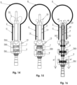
- the catheter 1, according to the present invention can simply be operated with one hand of the medical practitioner placed on distal part 36a of the handle 36 as well as on the tissue which surrounds the meatus of the urethra, while the other hand is used to push the medial part 36b of the handle 36 or the outer tube 4. As pressure is applied in the direction as indicated by the arrow 44 as shown in Fig.
- tubular membrane 2 unrolls progressively in the direction as indicated by the arrow 45 as shown in Fig. 11 to cover the walls of the urethra U.
- This "eversible" principle of motion of tubular membrane 2 during catheter 1 insertion prevents transport of bacteria from the region around the meatus of urethra and distal part of urethra to urinary bladder, but also reduces sliding friction, pain and trauma of epithelium of the urethra.
- the tubular membrane 2 pulls the body 3b of the inner tube 3 through the outer tube 4 as indicated by the arrow 46 as shown in Fig. 12 .
- the lengths of the body 3b of the inner tube 3, the outer tube 4 and tubular membrane 2 are sufficient to allow the tubular membrane 2 to cover the walls of the urethra and distal part 3a of inner tube 3 to enter the bladder.
- the nut 7 of the medial part 36b of the handle 36 and the nut 9 of the proximal part 36c of the handle 36 provide tight engagement between proximal part 36c, medial part 36b and distal part 36a of the handle 36.
- the proximal part 36c of the handle 36 is than tightly engaged with the medial part 36b of the handle 36, and medial part 36b of the handle 36 is tightly engaged with distal part 36a of the handle 36.
- the tubular membrane 2 encloses the hermetically sealed space 14.
- the medical practitioner Prior to removal of the catheter 1 from the urinary bladder, the medical practitioner must remove the fluid from the hermetically sealed space 14 through the hole 13, followed by unscrewing the nut 7 of the medial part 36b of the handle 36 and nut 9 of the proximal part 36c of the handle 36. As a result, the balloon 33 collapses allowing the catheter 1 to be removed ( Fig 15 ).
- the medical practitioner can easily use the catheter 1 only by one hand holding medial part 36b of the handle 36, while the other hand may pull proximal part 36c of the handle 36 or body 3b of the inner tube 3, in the direction as indicated by the arrow 47 as shown in Figure 16 .
- the tubular membrane 2 is drawn together with the exhausted balloon 33 in the direction as indicated by arrows 48 and 49 as shown in Figure 16 .
- the tubular membrane progressively uncovers the walls of the urethra, and the outer tube 4 moves in the direction as indicated by the arrow 50 ( Figure 16 ).
- sliding friction between tubular membrane 2 and urethra is reduced.
- the tubular membrane 2 should be made from material with ultrahigh strength characteristic, thin walls and compliance range from 0% to 10%. Preferably, the tubular membrane 2 is coated.
- Figure 17 shows distal membrane attachment 21 and proximal membrane attachment 22.
- the ballon 33 may vary in shape, size, position and number.
- the tubular memebrane 2 is made of two layers.
- the Inner layer 30 of the tubular membrane 2 is made from material with ultrahigh strength characteristic and low friction rate, thin walls and compliance range from 0% to 10%.
- the outer layer 31 of tubular membrane 2 is made from elastic material suitable for use in the direct contact with human tissues. These two layers are in connection between distal membrane attachment 21 and proximal membrane attachment 22. In addition, they are tightly engaged along their entire length, except within the balloon 33 where they are apart from each other.
- the inner layer 30 of tubular membrane 2 contains holes 32 within the balloon 33. Thus, fluid can flow through the holes 32 in both directions, allowing inflating and exhausting the balloon 33.
- the inner layer 30 of the tubular memebrane 2 and the outer layer 31 of tubular membrane 2 are positioned only within the balloon 33.
- the inner layer 30 of tubular membrane 2 is conected with outer layer 31 of tubular membrane 2 by the tight attachment 35 and distal membrane attachment 21.
- Inner layer 30 of tubular membrane 2 contains holes 32 within the balloon 33 and fluid can flow through these holes 32 in both directions this enabling the inflating or exhausting the balloon 33.
- the outer tube 4 contains apertures 34 of different shapes, which provide flexibility of the tube. Size, shape, position and number of these apertures 34 can be different to ensure flexibility and prevent twisting.
- Detail B view of the outer tube 4 containing apertures 34 along the walls of the outer tube 4 having lateral channels 15a, 15b of the outer tube 4 is presented in Fig. 21 .
Landscapes
- Health & Medical Sciences (AREA)
- Life Sciences & Earth Sciences (AREA)
- Biophysics (AREA)
- Pulmonology (AREA)
- Engineering & Computer Science (AREA)
- Anesthesiology (AREA)
- Biomedical Technology (AREA)
- Heart & Thoracic Surgery (AREA)
- Hematology (AREA)
- Animal Behavior & Ethology (AREA)
- General Health & Medical Sciences (AREA)
- Public Health (AREA)
- Veterinary Medicine (AREA)
- Epidemiology (AREA)
- Urology & Nephrology (AREA)
- Media Introduction/Drainage Providing Device (AREA)
- External Artificial Organs (AREA)
Claims (12)
- Cathéter (1) comprenant une poignée (36) ayant un trou (13), une membrane tubulaire (2) ayant une partie qui est partiellement agrandie pour former un ballonnet (33), un tube interne (3) étant fixé à la poignée (36) et ayant un corps (3b) et une partie distale (3a) du tube interne (3), la partie distale (3a) contenant des trous latéraux (11a, 11b), un tube externe (4), une ouverture proximale (10) du cathéter (1) qui peut être fixée à des sacs pour contenir des fluides corporels, la poignée (36) comprenant une partie proximale (36c) de la poignée (36), une partie médiane (36b) de la poignée (36) et une partie distale (36a) de la poignée (36), la partie proximale (36c) de la poignée (36) étant reliée de manière amovible à la partie médiane (36b) de la poignée (36) et la partie médiane (36b) de la poignée (36) étant reliée de manière amovible à la partie distale (36a) de la poignée (36), la membrane tubulaire (2) pouvant coulisser entre la partie distale (36a) de la poignée (36) et la partie distale (3a) du tube interne (3) à travers le tube externe (4), le tube externe (4) est lié de manière fixe à la partie médiane (36b) de la poignée (36) et le corps (3b) du tube interne (3) est monté sur la partie proximale (36c) de la poignée (36), la partie distale (36a) de la poignée (36) comprenant en outre une fixation de membrane proximale (22), le tube interne (3) comprenant en outre une fixation de membrane distale (21) pour une mise en prise étanche de la membrane tubulaire (2) avec la partie distale (3a) du tube interne (3), un diamètre de la partie distale (3a) du tube interne (3) étant inférieur à un diamètre du corps (3b) du tube interne (3), ladite partie distale (3a) du tube interne (3) ayant un trou (16) à l'extrémité de la partie distale (3a) du tube interne (3) et deux trous latéraux (11a, 11b) et un espace hermétiquement scellé (14) est intégré entre le tube externe (4) et la membrane tubulaire (2),
caractérisé en ce quela partie médiane (36b) de la poignée (36) comprend en outre un écrou (7), ledit écrou (7) venant en prise avec un filetage (26) de la partie distale (36a) de la poignée (36), et la partie proximale (36c) de la poignée (36) comprend un écrou (9), ledit écrou (9) venant en prise avecun filetage (25) de la partie médiane (36b) de la poignée (36), en ce quele tube externe (4) comprend en outre des canaux latéraux (15a, 15b) venant en prise avec des saillies (20a, 20b) de la partie distale (36a) de la poignée (36), respectivement, pour le coulissement de la partie distale (36a) de la poignée (36) le long du tube externe (4), le corps (3b) du tube interne (3) a des canaux latéraux (19a, 19b) venant en prise avec des saillies (24a, 24b) de la partie médiane (36b) de la poignée (36), respectivement, et
en ce queledit tube externe (4) présente une pointe arrondie (5). - Cathéter (1) selon la revendication 1, caractérisé en ce que la membrane tubulaire (2) et la partie distale (3a) du tube interne (3) sont enfermées à l'intérieur du tube externe (4).
- Cathéter (1) selon la revendication 1, caractérisé en ce que l'écrou (7) de la partie médiane (36b) de la poignée (36) et l'écrou (9) de la partie proximale (36c) de la poignée (36) sont vissés pour un engagement serré de la partie proximale (36c) de la poignée (36), de la partie médiane (36b) de la poignée (36) et de la partie distale (36a) de la poignée (36).
- Cathéter (1) selon la revendication 1 ou 3, caractérisé en ce que l'espace hermétiquement scellé (14) est gonflé avec un fluide par injection du fluide à travers le trou (13) de la poignée (36) et un diamètre d'espace hermétiquement scellé (14) est plus grand qu'un diamètre de la pointe arrondie (5) du tube externe (4).
- Cathéter (1) selon les revendications 1 à 4, caractérisé en ce que le trou (13) de la poignée (36) est disposé sur la partie distale (36a) de la poignée (36) ou sur la partie médiane (36b) de la poignée (36) ou sur la partie proximale (36c) de la poignée (36).
- Cathéter (1) selon les revendications 1 à 5, caractérisé en ce que la membrane tubulaire (2) est dotée d'un revêtement.
- Cathéter (1) selon les revendications 1 à 6, caractérisé en ce que la membrane tubulaire (2) contient une couche interne (30) et une couche externe (31).
- Cathéter (1) selon la revendication 7, caractérisé en ce que la couche interne (30) et la couche externe (31) sont mises en prise par la fixation de membrane distale (21) et la fixation de membrane proximale (22) et sont également étroitement mises en prise entre elles sur toute leur longueur, à l'exception du ballonnet (33) ou elles sont à l'écart l'une de l'autre.
- Cathéter (1) selon la revendication 7 ou 8, caractérisé en ce que la couche interne (30) de la membrane tubulaire (2) contient des trous (32) à l'intérieur du ballonnet (33).
- Cathéter (1) selon les revendications 7 à 9, caractérisé en ce que le ballonnet (33) renferme la membrane tubulaire (2) contenant la couche interne (30) et la couche externe (31).
- Cathéter (1) selon les revendications 7, 9 et 10, caractérisé en ce que la couche interne (30) de la membrane tubulaire (2) est associée à la couche externe (31) de la membrane tubulaire (2) par une fixation étanche (35) et la fixation de membrane distale (21).
- Cathéter (1) selon les revendications 1 à 11, caractérisé en ce que le tube extérieur (4) contient des ouvertures (34).
Applications Claiming Priority (1)
| Application Number | Priority Date | Filing Date | Title |
|---|---|---|---|
| PCT/RS2019/000004 WO2020153860A1 (fr) | 2019-01-21 | 2019-01-21 | Cathéter minimalement invasif |
Publications (3)
| Publication Number | Publication Date |
|---|---|
| EP3914329A1 EP3914329A1 (fr) | 2021-12-01 |
| EP3914329B1 true EP3914329B1 (fr) | 2023-06-07 |
| EP3914329C0 EP3914329C0 (fr) | 2023-06-07 |
Family
ID=65278437
Family Applications (1)
| Application Number | Title | Priority Date | Filing Date |
|---|---|---|---|
| EP19703205.5A Active EP3914329B1 (fr) | 2019-01-21 | 2019-01-21 | Cathéter minimalement invasif |
Country Status (7)
| Country | Link |
|---|---|
| US (1) | US11484688B2 (fr) |
| EP (1) | EP3914329B1 (fr) |
| CN (1) | CN113365686B (fr) |
| CA (1) | CA3126784C (fr) |
| IL (1) | IL284756A (fr) |
| RU (1) | RU2766731C1 (fr) |
| WO (1) | WO2020153860A1 (fr) |
Cited By (1)
| Publication number | Priority date | Publication date | Assignee | Title |
|---|---|---|---|---|
| US11957614B2 (en) | 2019-06-11 | 2024-04-16 | Convatec Technologies, Inc. | Urine collection bags for use with catheter products, kits incorporating the same, and methods therefor |
Families Citing this family (4)
| Publication number | Priority date | Publication date | Assignee | Title |
|---|---|---|---|---|
| US11724067B2 (en) | 2020-02-13 | 2023-08-15 | Scott Jewett | Eversible catheter with minimal rubbing friction |
| US12594399B2 (en) | 2021-04-12 | 2026-04-07 | Convatec Limited | Catheter |
| WO2023031966A1 (fr) * | 2021-09-01 | 2023-03-09 | Sunil Singh | Dispositif et procédé de protection de détérioration urétrale due à un gonflement accidentel d'une ampoule |
| US12377243B1 (en) * | 2024-10-01 | 2025-08-05 | Uropharma Limited | Intermittent intravesical therapeutic administration system |
Family Cites Families (30)
| Publication number | Priority date | Publication date | Assignee | Title |
|---|---|---|---|---|
| US3053257A (en) * | 1960-08-09 | 1962-09-11 | Davol Rubber Co | Catheter |
| US3583391A (en) | 1968-11-21 | 1971-06-08 | American Hospital Supply Corp | Medical instrument with outrolling catheter |
| US3908663A (en) | 1974-01-30 | 1975-09-30 | Nicholas F Viek | Catheter |
| US3911927A (en) * | 1974-04-17 | 1975-10-14 | Princeton Biomedix | Eversible catheter |
| US4863440A (en) * | 1985-12-23 | 1989-09-05 | Thomas J. Fogarty | Pressurized manual advancement dilatation catheter |
| US4871358A (en) * | 1987-11-09 | 1989-10-03 | Gold Steven K | Externally-based inversionary tube |
| EP0539084A1 (fr) * | 1991-10-18 | 1993-04-28 | Imagyn Medical, Inc. | Dispositif et procédé pour remuer indépendament un instrument dans un cathéter retroussable |
| US5458573A (en) * | 1992-05-01 | 1995-10-17 | American Biomed, Inc. | Everting toposcopic dilation catheter |
| US5387193A (en) | 1994-02-09 | 1995-02-07 | Baxter International Inc. | Balloon dilation catheter with hypotube |
| US6007521A (en) * | 1997-01-07 | 1999-12-28 | Bidwell; Robert E. | Drainage catheter system |
| US7402141B2 (en) * | 2003-08-27 | 2008-07-22 | Heuser Richard R | Catheter guidewire system using concentric wires |
| US7766899B2 (en) * | 2003-09-17 | 2010-08-03 | Prostalund Operations Ab | Partial-length, indwelling prostatic catheter using coiled inflation tube as an anchor and methods of draining urine and flushing clots |
| ITBA20040015A1 (it) * | 2004-04-20 | 2004-07-20 | Filippo Mastropasqua | Catetere iniettabile idrodinamico sterile atraumatico.dispositivo atto a cateterizzare l'uretra o assi vascolari in maniera incruenta , in modo del tutto sterile , con spinta progressiva di avanzamento assicurata da liquido,senza sfregamento sulle pa |
| US20070123798A1 (en) * | 2005-10-07 | 2007-05-31 | Tsion Israel Medical Systems Ltd. | Contamination protection device and method for use |
| WO2011080732A1 (fr) * | 2010-01-03 | 2011-07-07 | Angioslide Ltd. | Cathéter à ballonnet d'intussusception et procédé de fabrication et d'utilisation de ce cathéter |
| US9795408B2 (en) * | 2010-10-06 | 2017-10-24 | Cruzar Medsystems, Inc. | Catheter with vessel lining and methods for using same |
| WO2012155954A1 (fr) * | 2011-05-16 | 2012-11-22 | Brainlab Ag | Cathéter médical avec refoulement réduit |
| US11291434B2 (en) * | 2013-02-01 | 2022-04-05 | Nvision Medical Corporation | Systems, methods, and devices for fallopian tube diagnostics |
| US10639016B2 (en) * | 2013-02-01 | 2020-05-05 | Boston Scientific Scimed, Inc. | Methods and devices for Fallopian tube diagnostics |
| US10070853B2 (en) * | 2013-08-14 | 2018-09-11 | Covidien Lp | Expandable balloon desufflation assembly |
| US10245074B2 (en) * | 2013-11-11 | 2019-04-02 | Crossbay Medical, Inc. | Apparatus and methods for accessing and sealing bodily vessels and cavities |
| US10420454B2 (en) * | 2014-11-11 | 2019-09-24 | Ottek Ltd. | Hollow probe with sleeve |
| US9463035B1 (en) * | 2015-09-28 | 2016-10-11 | GW Medical LLC | Mechanical thrombectomy apparatuses and methods |
| KR20190008927A (ko) * | 2016-05-24 | 2019-01-25 | 엔비전 메디컬 코포레이션 | 가역적 자궁경 불임수술 |
| US10349957B2 (en) * | 2016-11-09 | 2019-07-16 | Cruzar Medsystems, Inc. | Systems and methods for traversing a site of obstruction |
| US11395674B2 (en) * | 2016-12-16 | 2022-07-26 | CARDINAL HEALTH SWITZERLAND 515 GmbH | Rotary debulking atherectomy device with a crossing balloon |
| GB2565843B (en) * | 2017-08-25 | 2019-09-25 | Strait Access Tech Holdings Pty Ltd | Invaginating device |
| WO2019084443A1 (fr) * | 2017-10-27 | 2019-05-02 | Nvision Medical Corporation | Cathéter à ballonnet à éversion pour administrer des substances dans une trompe de fallope |
| CN111343932B (zh) * | 2017-11-09 | 2023-05-30 | 斯瑞克公司 | 具有增强跟踪的翻转血栓切除设备 |
| US12551203B2 (en) * | 2018-12-28 | 2026-02-17 | Cellapax Corporation | Catheter with vessel lining for cell collection and methods for using same |
-
2019
- 2019-01-21 EP EP19703205.5A patent/EP3914329B1/fr active Active
- 2019-01-21 CA CA3126784A patent/CA3126784C/fr active Active
- 2019-01-21 US US17/423,850 patent/US11484688B2/en active Active
- 2019-01-21 WO PCT/RS2019/000004 patent/WO2020153860A1/fr not_active Ceased
- 2019-01-21 CN CN201980089532.8A patent/CN113365686B/zh active Active
- 2019-01-21 RU RU2021121929A patent/RU2766731C1/ru active
-
2021
- 2021-07-11 IL IL284756A patent/IL284756A/en unknown
Cited By (1)
| Publication number | Priority date | Publication date | Assignee | Title |
|---|---|---|---|---|
| US11957614B2 (en) | 2019-06-11 | 2024-04-16 | Convatec Technologies, Inc. | Urine collection bags for use with catheter products, kits incorporating the same, and methods therefor |
Also Published As
| Publication number | Publication date |
|---|---|
| WO2020153860A1 (fr) | 2020-07-30 |
| EP3914329C0 (fr) | 2023-06-07 |
| CA3126784A1 (fr) | 2020-07-30 |
| IL284756A (en) | 2021-08-31 |
| CA3126784C (fr) | 2023-12-19 |
| US11484688B2 (en) | 2022-11-01 |
| RU2766731C1 (ru) | 2022-03-15 |
| CN113365686A (zh) | 2021-09-07 |
| US20220040449A1 (en) | 2022-02-10 |
| EP3914329A1 (fr) | 2021-12-01 |
| CN113365686B (zh) | 2022-09-20 |
Similar Documents
| Publication | Publication Date | Title |
|---|---|---|
| CA3126784C (fr) | Catheter minimalement invasif | |
| US12005209B2 (en) | Balloon catheter | |
| US5569219A (en) | Collapsible catheter | |
| US11672948B2 (en) | Urinary catheter, kit and method | |
| EP2459264B1 (fr) | Cathéter ayant un drainage amélioré | |
| EP2349430B1 (fr) | DISPOSITIF et kit DE CATHÉTÉRISATION | |
| US5609583A (en) | Collapsible catheter | |
| US5637091A (en) | Collapsible catheter | |
| US6358229B1 (en) | Urinary drain | |
| US10245074B2 (en) | Apparatus and methods for accessing and sealing bodily vessels and cavities | |
| US11724067B2 (en) | Eversible catheter with minimal rubbing friction | |
| US5806527A (en) | Urethral plug with means for protection against infection | |
| US20130231639A1 (en) | Drainage Catheter | |
| EP2470249B1 (fr) | Cathéters | |
| US6558312B2 (en) | Intraurethral device for incontinence | |
| WO2021224248A1 (fr) | Cathéter | |
| US20220280278A1 (en) | Catheter | |
| HK1169621B (en) | Catheter having improved drainage |
Legal Events
| Date | Code | Title | Description |
|---|---|---|---|
| STAA | Information on the status of an ep patent application or granted ep patent |
Free format text: STATUS: UNKNOWN |
|
| STAA | Information on the status of an ep patent application or granted ep patent |
Free format text: STATUS: THE INTERNATIONAL PUBLICATION HAS BEEN MADE |
|
| PUAI | Public reference made under article 153(3) epc to a published international application that has entered the european phase |
Free format text: ORIGINAL CODE: 0009012 |
|
| STAA | Information on the status of an ep patent application or granted ep patent |
Free format text: STATUS: REQUEST FOR EXAMINATION WAS MADE |
|
| 17P | Request for examination filed |
Effective date: 20210819 |
|
| AK | Designated contracting states |
Kind code of ref document: A1 Designated state(s): AL AT BE BG CH CY CZ DE DK EE ES FI FR GB GR HR HU IE IS IT LI LT LU LV MC MK MT NL NO PL PT RO RS SE SI SK SM TR |
|
| DAV | Request for validation of the european patent (deleted) | ||
| RIC1 | Information provided on ipc code assigned before grant |
Ipc: A61M 25/10 20130101ALN20220825BHEP Ipc: A61M 25/04 20060101ALN20220825BHEP Ipc: A61M 25/00 20060101ALI20220825BHEP Ipc: A61M 25/01 20060101AFI20220825BHEP |
|
| GRAP | Despatch of communication of intention to grant a patent |
Free format text: ORIGINAL CODE: EPIDOSNIGR1 |
|
| STAA | Information on the status of an ep patent application or granted ep patent |
Free format text: STATUS: GRANT OF PATENT IS INTENDED |
|
| INTG | Intention to grant announced |
Effective date: 20221010 |
|
| GRAS | Grant fee paid |
Free format text: ORIGINAL CODE: EPIDOSNIGR3 |
|
| GRAA | (expected) grant |
Free format text: ORIGINAL CODE: 0009210 |
|
| STAA | Information on the status of an ep patent application or granted ep patent |
Free format text: STATUS: THE PATENT HAS BEEN GRANTED |
|
| AK | Designated contracting states |
Kind code of ref document: B1 Designated state(s): AL AT BE BG CH CY CZ DE DK EE ES FI FR GB GR HR HU IE IS IT LI LT LU LV MC MK MT NL NO PL PT RO RS SE SI SK SM TR |
|
| REG | Reference to a national code |
Ref country code: GB Ref legal event code: FG4D |
|
| REG | Reference to a national code |
Ref country code: CH Ref legal event code: EP Ref country code: AT Ref legal event code: REF Ref document number: 1573084 Country of ref document: AT Kind code of ref document: T Effective date: 20230615 Ref country code: DE Ref legal event code: R096 Ref document number: 602019030034 Country of ref document: DE |
|
| U01 | Request for unitary effect filed |
Effective date: 20230706 |
|
| U07 | Unitary effect registered |
Designated state(s): AT BE BG DE DK EE FI FR IT LT LU LV MT NL PT SE SI Effective date: 20230718 |
|
| REG | Reference to a national code |
Ref country code: LT Ref legal event code: MG9D |
|
| PG25 | Lapsed in a contracting state [announced via postgrant information from national office to epo] |
Ref country code: NO Free format text: LAPSE BECAUSE OF FAILURE TO SUBMIT A TRANSLATION OF THE DESCRIPTION OR TO PAY THE FEE WITHIN THE PRESCRIBED TIME-LIMIT Effective date: 20230907 Ref country code: ES Free format text: LAPSE BECAUSE OF FAILURE TO SUBMIT A TRANSLATION OF THE DESCRIPTION OR TO PAY THE FEE WITHIN THE PRESCRIBED TIME-LIMIT Effective date: 20230607 |
|
| PG25 | Lapsed in a contracting state [announced via postgrant information from national office to epo] |
Ref country code: RS Free format text: LAPSE BECAUSE OF FAILURE TO SUBMIT A TRANSLATION OF THE DESCRIPTION OR TO PAY THE FEE WITHIN THE PRESCRIBED TIME-LIMIT Effective date: 20230607 Ref country code: HR Free format text: LAPSE BECAUSE OF FAILURE TO SUBMIT A TRANSLATION OF THE DESCRIPTION OR TO PAY THE FEE WITHIN THE PRESCRIBED TIME-LIMIT Effective date: 20230607 Ref country code: GR Free format text: LAPSE BECAUSE OF FAILURE TO SUBMIT A TRANSLATION OF THE DESCRIPTION OR TO PAY THE FEE WITHIN THE PRESCRIBED TIME-LIMIT Effective date: 20230908 |
|
| PG25 | Lapsed in a contracting state [announced via postgrant information from national office to epo] |
Ref country code: SK Free format text: LAPSE BECAUSE OF FAILURE TO SUBMIT A TRANSLATION OF THE DESCRIPTION OR TO PAY THE FEE WITHIN THE PRESCRIBED TIME-LIMIT Effective date: 20230607 |
|
| PG25 | Lapsed in a contracting state [announced via postgrant information from national office to epo] |
Ref country code: IS Free format text: LAPSE BECAUSE OF FAILURE TO SUBMIT A TRANSLATION OF THE DESCRIPTION OR TO PAY THE FEE WITHIN THE PRESCRIBED TIME-LIMIT Effective date: 20231007 |
|
| PG25 | Lapsed in a contracting state [announced via postgrant information from national office to epo] |
Ref country code: SM Free format text: LAPSE BECAUSE OF FAILURE TO SUBMIT A TRANSLATION OF THE DESCRIPTION OR TO PAY THE FEE WITHIN THE PRESCRIBED TIME-LIMIT Effective date: 20230607 Ref country code: SK Free format text: LAPSE BECAUSE OF FAILURE TO SUBMIT A TRANSLATION OF THE DESCRIPTION OR TO PAY THE FEE WITHIN THE PRESCRIBED TIME-LIMIT Effective date: 20230607 Ref country code: RO Free format text: LAPSE BECAUSE OF FAILURE TO SUBMIT A TRANSLATION OF THE DESCRIPTION OR TO PAY THE FEE WITHIN THE PRESCRIBED TIME-LIMIT Effective date: 20230607 Ref country code: IS Free format text: LAPSE BECAUSE OF FAILURE TO SUBMIT A TRANSLATION OF THE DESCRIPTION OR TO PAY THE FEE WITHIN THE PRESCRIBED TIME-LIMIT Effective date: 20231007 Ref country code: CZ Free format text: LAPSE BECAUSE OF FAILURE TO SUBMIT A TRANSLATION OF THE DESCRIPTION OR TO PAY THE FEE WITHIN THE PRESCRIBED TIME-LIMIT Effective date: 20230607 |
|
| U20 | Renewal fee for the european patent with unitary effect paid |
Year of fee payment: 6 Effective date: 20240123 |
|
| PG25 | Lapsed in a contracting state [announced via postgrant information from national office to epo] |
Ref country code: PL Free format text: LAPSE BECAUSE OF FAILURE TO SUBMIT A TRANSLATION OF THE DESCRIPTION OR TO PAY THE FEE WITHIN THE PRESCRIBED TIME-LIMIT Effective date: 20230607 |
|
| REG | Reference to a national code |
Ref country code: DE Ref legal event code: R097 Ref document number: 602019030034 Country of ref document: DE |
|
| PLBE | No opposition filed within time limit |
Free format text: ORIGINAL CODE: 0009261 |
|
| STAA | Information on the status of an ep patent application or granted ep patent |
Free format text: STATUS: NO OPPOSITION FILED WITHIN TIME LIMIT |
|
| 26N | No opposition filed |
Effective date: 20240308 |
|
| PG25 | Lapsed in a contracting state [announced via postgrant information from national office to epo] |
Ref country code: MC Free format text: LAPSE BECAUSE OF FAILURE TO SUBMIT A TRANSLATION OF THE DESCRIPTION OR TO PAY THE FEE WITHIN THE PRESCRIBED TIME-LIMIT Effective date: 20230607 |
|
| PG25 | Lapsed in a contracting state [announced via postgrant information from national office to epo] |
Ref country code: MC Free format text: LAPSE BECAUSE OF FAILURE TO SUBMIT A TRANSLATION OF THE DESCRIPTION OR TO PAY THE FEE WITHIN THE PRESCRIBED TIME-LIMIT Effective date: 20230607 |
|
| REG | Reference to a national code |
Ref country code: CH Ref legal event code: PL |
|
| GBPC | Gb: european patent ceased through non-payment of renewal fee |
Effective date: 20240121 |
|
| PG25 | Lapsed in a contracting state [announced via postgrant information from national office to epo] |
Ref country code: GB Free format text: LAPSE BECAUSE OF NON-PAYMENT OF DUE FEES Effective date: 20240121 |
|
| PG25 | Lapsed in a contracting state [announced via postgrant information from national office to epo] |
Ref country code: CH Free format text: LAPSE BECAUSE OF NON-PAYMENT OF DUE FEES Effective date: 20240131 |
|
| PG25 | Lapsed in a contracting state [announced via postgrant information from national office to epo] |
Ref country code: GB Free format text: LAPSE BECAUSE OF NON-PAYMENT OF DUE FEES Effective date: 20240121 Ref country code: CH Free format text: LAPSE BECAUSE OF NON-PAYMENT OF DUE FEES Effective date: 20240131 |
|
| PG25 | Lapsed in a contracting state [announced via postgrant information from national office to epo] |
Ref country code: IE Free format text: LAPSE BECAUSE OF NON-PAYMENT OF DUE FEES Effective date: 20240121 |
|
| PG25 | Lapsed in a contracting state [announced via postgrant information from national office to epo] |
Ref country code: IE Free format text: LAPSE BECAUSE OF NON-PAYMENT OF DUE FEES Effective date: 20240121 |
|
| U20 | Renewal fee for the european patent with unitary effect paid |
Year of fee payment: 7 Effective date: 20250121 |
|
| PG25 | Lapsed in a contracting state [announced via postgrant information from national office to epo] |
Ref country code: CY Free format text: LAPSE BECAUSE OF FAILURE TO SUBMIT A TRANSLATION OF THE DESCRIPTION OR TO PAY THE FEE WITHIN THE PRESCRIBED TIME-LIMIT; INVALID AB INITIO Effective date: 20190121 |
|
| PG25 | Lapsed in a contracting state [announced via postgrant information from national office to epo] |
Ref country code: HU Free format text: LAPSE BECAUSE OF FAILURE TO SUBMIT A TRANSLATION OF THE DESCRIPTION OR TO PAY THE FEE WITHIN THE PRESCRIBED TIME-LIMIT; INVALID AB INITIO Effective date: 20190121 |
|
| PG25 | Lapsed in a contracting state [announced via postgrant information from national office to epo] |
Ref country code: TR Free format text: LAPSE BECAUSE OF FAILURE TO SUBMIT A TRANSLATION OF THE DESCRIPTION OR TO PAY THE FEE WITHIN THE PRESCRIBED TIME-LIMIT Effective date: 20230607 |