EP3914399B1 - Steigrohrsichter - Google Patents
Steigrohrsichter Download PDFInfo
- Publication number
- EP3914399B1 EP3914399B1 EP20701551.2A EP20701551A EP3914399B1 EP 3914399 B1 EP3914399 B1 EP 3914399B1 EP 20701551 A EP20701551 A EP 20701551A EP 3914399 B1 EP3914399 B1 EP 3914399B1
- Authority
- EP
- European Patent Office
- Prior art keywords
- riser pipe
- conveying air
- air
- conveying
- pipe
- Prior art date
- Legal status (The legal status is an assumption and is not a legal conclusion. Google has not performed a legal analysis and makes no representation as to the accuracy of the status listed.)
- Active
Links
Images

Classifications
-
- B—PERFORMING OPERATIONS; TRANSPORTING
- B07—SEPARATING SOLIDS FROM SOLIDS; SORTING
- B07B—SEPARATING SOLIDS FROM SOLIDS BY SIEVING, SCREENING, SIFTING OR BY USING GAS CURRENTS; SEPARATING BY OTHER DRY METHODS APPLICABLE TO BULK MATERIAL, e.g. LOOSE ARTICLES FIT TO BE HANDLED LIKE BULK MATERIAL
- B07B7/00—Selective separation of solid materials carried by, or dispersed in, gas currents
- B07B7/08—Selective separation of solid materials carried by, or dispersed in, gas currents using centrifugal force
- B07B7/10—Selective separation of solid materials carried by, or dispersed in, gas currents using centrifugal force having air recirculating within the apparatus
-
- B—PERFORMING OPERATIONS; TRANSPORTING
- B07—SEPARATING SOLIDS FROM SOLIDS; SORTING
- B07B—SEPARATING SOLIDS FROM SOLIDS BY SIEVING, SCREENING, SIFTING OR BY USING GAS CURRENTS; SEPARATING BY OTHER DRY METHODS APPLICABLE TO BULK MATERIAL, e.g. LOOSE ARTICLES FIT TO BE HANDLED LIKE BULK MATERIAL
- B07B11/00—Arrangement of accessories in apparatus for separating solids from solids using gas currents
- B07B11/04—Control arrangements
-
- B—PERFORMING OPERATIONS; TRANSPORTING
- B07—SEPARATING SOLIDS FROM SOLIDS; SORTING
- B07B—SEPARATING SOLIDS FROM SOLIDS BY SIEVING, SCREENING, SIFTING OR BY USING GAS CURRENTS; SEPARATING BY OTHER DRY METHODS APPLICABLE TO BULK MATERIAL, e.g. LOOSE ARTICLES FIT TO BE HANDLED LIKE BULK MATERIAL
- B07B7/00—Selective separation of solid materials carried by, or dispersed in, gas currents
- B07B7/08—Selective separation of solid materials carried by, or dispersed in, gas currents using centrifugal force
- B07B7/083—Selective separation of solid materials carried by, or dispersed in, gas currents using centrifugal force generated by rotating vanes, discs, drums, or brushes
-
- B—PERFORMING OPERATIONS; TRANSPORTING
- B07—SEPARATING SOLIDS FROM SOLIDS; SORTING
- B07B—SEPARATING SOLIDS FROM SOLIDS BY SIEVING, SCREENING, SIFTING OR BY USING GAS CURRENTS; SEPARATING BY OTHER DRY METHODS APPLICABLE TO BULK MATERIAL, e.g. LOOSE ARTICLES FIT TO BE HANDLED LIKE BULK MATERIAL
- B07B7/00—Selective separation of solid materials carried by, or dispersed in, gas currents
- B07B7/08—Selective separation of solid materials carried by, or dispersed in, gas currents using centrifugal force
- B07B7/086—Selective separation of solid materials carried by, or dispersed in, gas currents using centrifugal force generated by the winding course of the gas stream
Definitions
- the invention relates to a riser pipe classifier, comprising a riser pipe for the pneumatic transport of granular material suspended in conveying air, wherein the riser pipe has a vertical conveying direction component, a swirling device arranged in the riser pipe, which imparts a swirl to the conveying air, a dip pipe arranged above the swirling device, which extends the air path for the conveying air, wherein an annular gap is present between the riser pipe and the dip pipe, through which coarse-grained material, which has been thrown outwards in a radial direction with respect to the conveying direction of the conveying air by the swirl of the conveying air, separates from the conveying air flowing into the dip pipe, and a circulating grinding plant comprising such a classifier.
- the classifying principle is based on exploiting the inertia principle of coarser grains, which are conveyed differently by the air in which they are suspended. A larger grain is less affected by the conveying air due to the lower air resistance in relation to its volume and weight than a smaller grain, which is more strongly carried by the conveying air.
- the way in which the conveying air acts on the material to be separated varies depending on the type of classifier.
- a very important aspect when selecting a classifier for a specific purpose is the classifier efficiency, i.e. the separation performance in a single Throughput, the associated pressure loss of the conveying air in which the material to be separated is suspended, the costs for maintaining the separator if the separator has moving components, the maintenance effort, the tendency to become blocked in the event of a sudden plant shutdown, the installation height, which with each meter consumes additional energy to convey the material to be separated against gravity, and also the assembly time for the initial installation in an existing plant in which the separation of the material to be separated into its grain size fractions is to take place.
- German patent DE 832 238 B discloses a riser separator according to the preamble of claim 1.
- This patent describes an air separator.
- a swirl element is arranged in the discharge pipe. The swirl element is thus located downstream of the gas stream from the separation point.
- a separator is revealed.
- conveying air with suspended material to be separated is pneumatically conveyed through a riser pipe.
- a swirler is arranged in the riser pipe, which imparts a swirl to the rising air.
- At the end of the riser pipe is a transition to an expansion chamber.
- a dip tube dips into the expansion chamber. This arrangement allows the material to be separated into a coarse material fraction and a fine material fraction.
- German patent De 1,218,264 A sifter with its spreading disc is revealed, which operates like a reversed rod basket sifter.
- the spreading disc throws the material to be separated into a collecting chamber.
- the object of the invention is therefore to provide such a classifier.
- riser pipe classifier having the features of claim 1. Further advantageous embodiments of the riser pipe classifier are specified in the subclaims to claim 1. A circulating grinding plant comprising this type of classifier is specified in claim 5.
- the classifier is integrated into a pneumatic conveying pipe, wherein the pneumatic conveying pipe has a vertical conveying direction component.
- the separation of the material to be separated into at least two grain size fractions occurs when a swirling device in the riser pipe imparts a swirl to the conveying air.
- the conveying air thus moves with a linear and vertical directional component as well as with an approximately circular rotational component.
- These two directional components lead to a roughly helical flow.
- the grains suspended in the conveying air experience a centrifugal force.
- the larger grains experience lower air resistance in the viscous air in relation to their own mass and thus to the centrifugal force acting on them than grains with a smaller grain size.
- This effect is based on the fact that the smaller grains are better supported due to the air viscosity.
- the larger grains thus collect in the outer region of the vortex, the helically flowing conveying air.
- an annular gap is formed between a dip tube which is inserted into the riser tube, and the riser tube itself. This annular gap separates the outer region of the vortex from the inner region of the conveying air vortex.
- the inner region of the vortex which carries the smaller grain sizes, flows into the dip tube that dips into the riser tube.
- the outer region of the conveying air vortex which carries the larger grains with the larger average diameter, flows into the annular gap.
- the riser pipe classifier comprising a riser pipe for the pneumatic transport of granular material suspended in conveying air, wherein the riser pipe has a vertical conveying direction component, a swirling device arranged in the riser pipe, which imparts a swirl to the conveying air, a dip pipe arranged above the swirling device, which extends the air path for the conveying air, wherein between the riser pipe and the dip pipe there is an annular gap through which coarse-grained material, which has been thrown outwards in a radial direction with respect to the conveying direction of the conveying air by the swirl of the conveying air, separates from the conveying air flowing into the dip pipe.
- the swirling device of the riser sifter according to the invention can be designed in different ways.
- the swirling device consists of an impeller arranged approximately centrally in the riser pipe. If the impeller is static, it is fixed in the center of the riser pipe. As the conveying air passes over the impeller, it experiences a swirl that leads to a helical flow and the formation of a vortex with the desired effect explained above.
- the static, but height- and angle-adjustable impeller has the advantage of a particularly favorable design with only a low pressure loss during the formation of a vortex, whereby the magnitude of the pressure loss depends on the air resistance of the impeller.
- the impeller can be driven.
- the impeller thus has a stimulating effect and also the effect of creating a vortex.
- the qualitative separation efficiency is also an important parameter for the use of a classifier in a plant.
- the height of the swirling device in relation to the annular gap can be variable and adjustable.
- the swirling device can be suspended in the riser pipe on a ring segment or in a cage, with the ring segment or cage being adjustable via a vertical slot in the riser pipe.
- the cage or ring segment can be attached from the outside in various positions through the slot.
- the vertical slot in the riser pipe can be covered from the outside to maintain the pressure in the riser pipe.
- the impeller can be angle-adjustable. This feature helps optimize the turbulence effect when the impeller's flow is not ideal.
- a specific application for the immersion tube classifier presented here is a recirculation grinding plant, in which a fraction with larger grains is fed back into the grinding circuit.
- a recirculation grinding plant comprising a comminution device, such as an impact hammer mill, a high-pressure roller press or a roller mill, a downpipe through which Ground material is fed onto the comminution device, and a riser pipe classifier as described above, a housing which separates the conveying air from the atmospheric air, wherein the riser pipe of the riser pipe classifier and the downpipe are connected to the housing, wherein the annular gap is connected to the downpipe.
- a comminution device such as an impact hammer mill, a high-pressure roller press or a roller mill
- a downpipe through which Ground material is fed onto the comminution device
- a riser pipe classifier as described above
- a housing which separates the conveying air from the atmospheric air, wherein the riser pipe of the riser pipe classifier and the down
- FIG 1 1 shows a sketch of a circulating grinding plant in which the riser pipe classifier 1 according to the invention is integrated.
- the riser pipe classifier 1 consists of a riser pipe 5 for the pneumatic transport of granular material 15 suspended in conveying air 10.
- the riser pipe 5 always has a vertical conveying direction component.
- the conveying direction is exactly vertical.
- the riser pipe classifier 1 has a swirling device 20 arranged in the riser pipe 5, which imparts a swirl to the conveying air 10.
- a dip pipe 25 is arranged, which extends the air path for the conveying air 10.
- an annular gap 30 is present between the riser pipe 5 and the dip pipe 10.
- Coarse-grained material 35 is separated from the conveying air 10 through the annular gap 30 because the coarse-grained material 35 has been propelled outward in a radial direction relative to the conveying direction of the conveying air 10, i.e., toward the wall of the riser pipe 1, by the swirl of the conveying air 10. The remainder of the conveying air 10 flows into the immersion pipe 25.
- FIG 2 is the Figure 1 Detail enclosed by rectangle A is shown enlarged.
- the conveying air 10 which is fed from below into
- the fluid flowing into the riser pipe 1 is given a swirl by the swirling device, here a static impeller, but optionally also a height-adjustable and/or angle-adjustable impeller.
- the swirl in is in Figure 2 represented by the wavy lines.
- Coarser grains of the material to be separated are carried outwards against the air resistance by the centrifugal force acting on them during the swirling movement.
- the track of a single grain of the material to be separated is therefore approximately that of an upwardly expanding spiral.
- annular gap 30 In the upper part of the riser tube 1 there is an annular gap 30 between the immersion tube 25, which projects downwards into the riser tube 1, and the riser tube 1 itself. This annular gap 30 separates the front between a fraction of coarse-grained material and a fraction with finer material, which is discharged through the immersion tube 25.
- the height adjustability is indicated by the double arrow to the right of the impeller 20 and the angle adjustability by the angle symbol ⁇ .
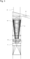
- FIG 3 A sketch is shown to help understand the effect of adjusting the height of the swirling device.
- the swirling device creates a vortex, with more coarse-grained material 35 being present in the outer regions of the vortex.
- This coarse-grained material 35 is slowly carried outwards on its journey from the swirling device 20 to the annular gap 30.
- the annular gap 30 encounters a front in the darker and outer region of the grain size front represented as a truncated cone, which differs depending on the height of the swirling device 20.
- the grain size fraction can therefore be varied depending on the front position. If the swirling device 20 is pushed upwards, the coarse-grained material will contain more finer material than if the swirling device is pushed downwards.
- FIG. 1 It shows how the riser pipe classifier 1, a housing 50 for an impact hammer mill as comminution device 40, and a downpipe 45 for feeding the ground material are connected to one another, thus separating the conveying air 10 from the atmospheric air.
- Ground material 55 which is fed through the downpipe 45 onto the impact hammer mill as comminution device 40, is comminuted there and conveyed by the conveying air 10 through the swirling device 20.
- the swirling device swirls the conveying air with the ground material suspended therein, whereby, as described, the ground material is separated into different fractions of varying grain size composition.
- the fraction with coarse-grained material 35 flows back into the downpipe through the annular gap 30, which is connected to the downpipe 45, so that coarse-grained material 35 is again fed to the impact hammer mill as comminution device 40. Fine material, however, is discharged through the dip tube 25.
Landscapes
- Combined Means For Separation Of Solids (AREA)
- Cyclones (AREA)
Description
- Die Erfindung betrifft Steigrohrsichter, aufweisend ein Steigrohr für den pneumatischen Transport von in Förderluft suspendiertem körnigen Gut, wobei das Steigrohr eine vertikale Förderrichtungskomponente aufweist, eine in dem Steigrohr angeordnete Verwirbelungsvorrichtung, welche der Förderluft einen Drall verleiht, ein oberhalb der Verwirbelungsvorrichtung angeordnetes Tauchrohr, welche den Luftweg für die Förderluft verlängert, wobei zwischen dem Steigrohr und dem Tauchrohr ein Ringspalt vorhanden ist, durch welchen grobkörniges Gut, welches durch den Drall der Förderluft in radialer Richtung in Bezug auf die Förderrichtung der Förderluft nach außen geschleudert wurde, aus der Förderluft, die in das Tauchrohr strömt, ausscheidet, und eine Kreislaufmahlanlage aufweisend einen solchen Sichter.
- Zum Trennen von körnigem Gut in seine Korngrößenfraktionen ist es bekannt, das körnige Gut in Förderluft zu suspendieren und mit Hilfe eines Windsichters in zumindest zwei, manchmal auch drei Korngrößenfraktionen zu unterteilen. Das Sichterprinzip basiert je nach Sichtertyp auf der Ausnutzung des Trägheitsprinzips gröberer Körner, die durch die Luft, in der sie suspendiert sind, unterschiedlich gefördert werden. Ein größeres Korn wird durch den geringeren Luftwiderstand im Verhältnis zum Volumen und seinem Gewicht weniger von der Förderluft beeinflusst als ein kleineres Korn, das durch die Förderluft stärker getragen wird. Die Art und Weise wie die Förderluft auf das Trenngut wirkt, ist dabei bei jedem Sichtertyp unterschiedlich.
- Ein sehr wesentlicher Aspekt bei der Auswahl eines Sichters für einen bestimmten Zweck ist die Sichtereffizienz, also die Trennleistung bei einem einmaligen Durchlauf, der dabei hinzunehmende Druckverlust der Förderluft, in der das Trenngut suspendiert ist, die Kosten für den Unterhalt des Sichters, wenn der Sichter bewegliche Komponenten aufweist, der Wartungsaufwand, die Neigung, bei plötzlichem Anlagenstillstand zu verstopfen, die Bauhöhe, die mit jedem Meter zusätzliche Energie zum Fördern des Trennguts entgegen der Schwerkraft zehrt, und auch die Montagezeit für den erstmaligen Einbau in eine bestehende Anlage, in der die Trennung von Trenngut in seine Korngrößenfraktionen erfolgen soll.
- Sehr effiziente, hochwirksame Sichtertypen sind im Stand der Technik bekannt, wie zum Beispiel Stabkorbsichter. Diese haben allerdings den Nachteil, dass sie Wartungsaufwändig sind, elektrische Energie zum Antrieb des Stabkorbs verbrauchen und eine gewisse Mindestbauhöhe erfordern.
- In dem deutschen Patent
DE 832 238 B wird einen Steigrohrsichter gemäß dem Oberbegriff des Anspruch 1 offenbart. In diesem Patent ist ein Windsichter beschrieben. Darin ist im Ausblasrohr, ein Verwirbelungskörper angeordnet. Der Verwirbelungskörper befindet sich somit gasstromabwärts des Trennortes. - In dem US-Patent
US 1,724,041 wird ein Sichter offenbart. In diesem wird Förderluft mit darin suspendiertem Trenngut durch ein Steigrohr pneumatisch gefördert. In dem Steigrohr ist ein Verwirbelungskörper angeordnet, durch den die Steigluft einen Drall erhält. Am Ende des Steigrohrs befindet sich ein Übergang zu einer Expansionskammer. Ein Tauchrohr taucht in die Expansionskammer hinein. Durch diese Anordnung lässt sich Trenngut in eine Grobgutfraktion und in eine Feingutfraktion auftrennen. - In der deutschen Offenlegungsschrift
DE 25 56 970 wird ein Sichter in Form eines Zyklonsichters offenbart. In den Zyklonsichter taucht ein Flügelrad, um die Verwirbelung zu unterstützen. Ein expliziter Ringspalt ist nicht vorhanden. - In der europäischen Patentanmeldung
EP 0 164 859 A2 wird ein Sichter offenbart, der im Weg der aufsteigenden Sichtluft mit darin suspendiertem Trenngut ein Flügelrad aufweist. Das Flügelrad schleudert das Trenngut nach außen in einen Auffangraum. - In dem deutsche Patent
De 1 218 264 wird ein Sichter mit seinem Streuteller offenbart, der wie ein reversierter Stabkorbsichter arbeitet. Der Streuteller schleudert abzutrennendes Trenngut in einen Auffangraum. - Es besteht der Bedarf eines einfachen Sichtertyps mit mittlerer Effizienz, aber sehr geringen Herstellungs- und Einbaukosten und mit geringem hinzunehmenden Druckverlust. Aufgabe der Erfindung ist es daher, einen solchen Sichter zur Verfügung zu stellen.
- Die erfindungsgemäße Aufgabe wird gelöst, durch einen Steigrohrsichter mit den Merkmalen nach Anspruch 1. Weitere vorteilhafte Ausgestaltungen des Steigrohrsichters sind in den Unteransprüchen zu Anspruch 1 angegeben. Eine Kreislaufmahlanlage aufweisend diesen Sichtertyp ist in Anspruch 5 angegeben.
- Nach der Erfindung ist vorgesehen, den Sichter in ein pneumatisches Förderrohr zu integrieren, wobei das pneumatische Förderrohr eine vertikale Förderrichtungskomponente aufweist. Die Auftrennung des Trennguts in mindestens zwei Korngrößenfraktionen geschieht dadurch, dass eine in dem Steigrohr vorhandene Verwirbelungsvorrichtung der Förderluft einen Drall verleiht. Die Förderluft bewegt sich so mit einer linearen und vertikalen Richtungskomponente als auch mit einer etwa kreisförmigen Umdrehungskomponente. Diese beiden Richtungskomponenten führen zu einer etwa helikalen Strömung. Bei der helikalen Strömung erfahren die in der Förderluft suspendierten Körner eine Zentrifugalkraft. Die gröberen Körner erfahren in der viskosen Luft einen geringeren Luftwiderstand im Verhältnis zu ihrer eigenen Masse und damit zu ihrer auf sie wirkenden Zentrifugalkraft als Körner mit geringerer Korngröße. Dieser Effekt basiert auf der Tatsache, dass die kleineren Körner aufgrund der Luftviskosität besser getragen werden. Die gröberen Körner sammeln sich so im Außenbereich des Wirbels, der helikal strömenden Förderluft. In einer vorbestimmten Höhe oberhalb der Verwirbelungsvorrichtung ist ein Ringspalt zwischen einem Tauchrohr, das in das Steigrohr eintaucht, und dem Steigrohr selbst. Dieser Ringspalt trennt den äußeren Bereich des Wirbels vom inneren Bereich des Wirbels der Förderluft. Der innere Bereich des Wirbels, der die Körner mit geringerer Korngröße trägt, strömt in das in das Steigrohr eintauchende Tauchrohr. Hingegen strömt der äußere Bereich des Wirbels der Förderluft, der die gröberen Körner mit dem größeren mittleren Durchmesser, in den Ringspalt. Zur Durchführung exakt dieser Arbeitsweise wird der Steigrohrsichter beansprucht, aufweisend ein Steigrohr für den pneumatischen Transport von in Förderluft suspendiertem körnigen Gut, wobei das Steigrohr eine vertikale Förderrichtungskomponente aufweist, eine in dem Steigrohr angeordnete Verwirbelungsvorrichtung, welche der Förderluft einen Drall verleiht, ein oberhalb der Verwirbelungsvorrichtung angeordnetes Tauchrohr, welche den Luftweg für die Förderluft verlängert, wobei zwischen dem Steigrohr und dem Tauchrohr ein Ringspalt vorhanden ist, durch welchen grobkörniges Gut, welches durch den Drall der Förderluft in radialer Richtung in Bezug auf die Förderrichtung der Förderluft nach außen geschleudert wurde, aus der Förderluft, die in das Tauchrohr strömt, ausscheidet.
- Die Verwirbelungsvorrichtung des erfindungsgemäßen Steigrohrsichters kann unterschiedlich ausgestaltet sein. In bevorzugter Ausführungsform besteht die Verwirbelungsvorrichtung aus einem im Steigrohr etwa mittig angeordnetem Impeller. Ist der Impeller statisch, so steht dieser fest in der Mitte des Steigrohrs. Überstreicht die Förderluft den Impeller so erfährt diese einen Drall, der zu einer helikalen Strömung unter Ausbildung eines Wirbels mit der eingangs erklärten und erwünschten Wirkung führt. Der statische, aber höhen- und winkelverstellbare verstellbare Impeller hat den Vorteil eines besonders günstigen Aufbaus mit einem nur geringen Druckverlust bei der Ausbildung eines Wirbels, wobei die Größenordnung des Druckverlusts vom Luftwiderstand des Impellers abhängt.
- Um die Verwirbelung zu verstärken und damit die Trennleistung zu erhöhen, kann vorgesehen sein, den Impeller anzutreiben. Der Impeller hat somit eine fördernde Wirkung und auch die Wirkung der Ausbildung eines Wirbels.
- Neben der quantitativen Trennleistung, also das Verhältnis der Korngrößenmenge ab einer bestimmten Größe in der Grobfraktion zum Verhältnis der gesamten Grobkornfraktion ab dieser bestimmten Größe im gesamten Trenngut ist auch die qualitative Trennwirkung ein wichtiger Parameter, der für den Einsatz eines Sichters in einer Anlage wichtig ist. Um die qualitative Trennwirkung zu beeinflussen, kann vorgesehen sein, dass die Höhenlage der Verwirbelungsvorrichtung im Verhältnis zum Ringspalt variabel und einstellbar ist. Im einfachsten Fall kann die Verwirbelungsvorrichtung in dem Steigrohr an einem Ringsegment oder in einem Käfig aufgehangen sein, wobei das Ringsegment oder der Käfig durch einen vertikalen Schlitz im Steigrohr verstellbar ist. Durch den Schlitz lässt sich der Käfig oder das Ringsegment von außen an verschiedenen Positionen befestigen. Wobei der vertikale Schlitz im Steigrohr zur Wahrung des Drucks im Steigrohr von außen abgedeckt werden kann. Es ist auch möglich einen helikalen Schlitz im Steigrohr vorzusehen und durch Verdrehen eines mit dem Ringsegment oder dem Käfig durch den Schlitz ragenden Stellhebel die Höhenlage der Verwirbelungsvorrichtung einzustellen. Bei der Änderung der Höhenlage greift die Trennwirkung des Ringspaltes, der den äußeren Teil des Wirbels der Förderluft von dem inneren Teil des Wirbels trennt, an verschiedenen Stellen eines stationären Zustands der Korngrößenverteilung innerhalb des Wirbels an. Dadurch ändert sich die Korngrößenzusammensetzung der beiden Fraktionen, die einmal in das Tauchrohr strömen und einem in den Ringspalt.
- Schließlich kann vorgesehen sein, den Impeller winkelverstellbar zu machen. Diese Funktion hilft, bei nicht idealer Anströmung des Impellers die Verwirbelungswirkung zu optimieren.
- Eine konkrete Anwendung für den hier vorgestellten Tauchrohrsichter ist eine Kreislaufmahlanlage, bei der eine Fraktion mit größeren Körnern erneut dem Mahlkreislauf zugeführt wird. Hierzu wird eine Kreislaufmahlanlage beansprucht, aufweisend eine Zerkleinerungsvorrichtung, wie eine Prallhammermühle, eine Hochdruck-Rollenpresse oder eine Wälzmühle, ein Fallrohr, durch welches Mahlgut auf die Zerkleinerungsvorrichtung aufgegeben wird, und ein Steigrohrsichter wie er vorstehend beschrieben ist, eine Einhausung, welche die Förderluft von der atmosphärischen Luft trennt, wobei das Steigrohr des Steigrohrsichters und das Fallrohr mit der Einhausung verbunden sind, wobei der Ringspalt mit dem Fallrohr verbunden ist.
- Die Erfindung wird anhand der folgenden Figuren näher erläutert. Es zeigt:
- Fig. 1
- einen Steigrohrsichter als Teil einer Kreislaufmahlanlage,
- Fig. 2
- eine Ausschnittsvergrößerung aus
Figur 1 darstellend den Steigrohrsichter selbst, - Fig. 3
- eine Skizze zur Verdeutlichung des Einflusses der Höhenlage der Verwirbelungsvorrichtung auf die qualitative Trennleistung
- In
Figur 1 ist eine Skizze mit einer Kreislaufmahlanlage dargestellt, in welcher der erfindungsgemäße Steigrohrsichter 1 integriert ist. Der Steigrohrsichter 1 besteht aus einem ein Steigrohr 5 für den pneumatischen Transport von in Förderluft 10 suspendiertem körnigen Gut 15. Das Steigrohr 5 weist stets eine vertikale Förderrichtungskomponente auf. In dem hier dargestellten Steigrohrsichter 1 ist die Förderrichtung exakt vertikal. Des Weiteren weist der Steigrohrsichter 1 eine in dem Steigrohr 5 angeordnete Verwirbelungsvorrichtung 20 auf, welche der Förderluft 10 einen Drall verleiht. Oberhalb der Verwirbelungsvorrichtung 20 ist ein Tauchrohr 25 angeordnet, welche den Luftweg für die Förderluft 10 verlängert. Es ist nach der Erfindung vorgesehen, dass zwischen dem Steigrohr 5 und dem Tauchrohr 10 ein Ringspalt 30 vorhanden ist. Durch den Ringspalt 30 scheidet grobkörniges Gut 35 aus der Förderluft 10 aus, weil das grobkörnige Gut 35 durch den Drall der Förderluft 10 in radialer Richtung in Bezug auf die Förderrichtung der Förderluft 10 nach außen, also in Richtung der Wand des Steigrohrs 1, geschleudert wurde. Der Rest der Förderluft 10 strömt in das Tauchrohr 25. - In
Figur 2 ist die inFigur 1 durch ein Rechteck A eingegrenzte Einzelheit vergrößert dargestellt. IFigur 2 wird gezeigt, dass die Förderluft 10, die von unten in das Steigrohr 1 einströmt, durch die Verwirbelungsvorrichtung, hier ein statischer, aber optional auch höhenverstellbarer und/oder winkelverstellbarer Impeller, einen Drall erhält. Der Drall in ist inFigur 2 durch die Wellenlinien dargestellt. Gröbere Körnchen des Trennguts werden bei der Wirbelbewegung durch die auf sie wirkende Zentrifugalkraft gegen den Luftwiderstand nach außen getragen. Somit ist die Spur eines einzigen Korns des Trennguts etwa die einer sich nach oben erweiternden Spirale. Im oberen Teil des Steigrohrs 1 ist ein Ringspalt 30 zwischen dem Tauchrohr 25, das nach unten in das Steigrohr ragt 1, und dem Steigrohr 1 selbst vorhanden. Dieser Ringspalt 30 trennt die Front zwischen einer Fraktion aus grobkörnigem Gut und einer Fraktion mit feinerem Gut, das durch das Tauchrohr 25 abgeleitet wird. Die Höhenverstellbarkeit ist durch den Doppelpfeil rechts neben dem Impeller 20 angedeutet und die Winkelverstellbarkeit durch das Winkelsymbol α. - In
Figur 3 ist eine Skizze dargestellt, die zum Verständnis des Effekts der Höhenverstellung der Verwirbelungsvorrichtung dient. Die Verwirbelungsvorrichtung führt zu einem Wirbel, wobei in den äußeren Bereichen des Wirbels mehr grobkörniges Gut 35 vorhanden ist. Dieses grobkörnige Gut 35 wird auf der Reise von der Verwirbelungsvorrichtung 20 bis zum Ringspalt 30 langsam nach außen getragen. Dadurch bildet sich eine konusartig ausgebildete Front zwischen Feingut und grobkörnigem Gut 35, die hier durch den nach außen dunkler werdenden und auf dem Kopf stehenden Kegelstumpf dargestellt ist. Wird nun die Verwirbelungsvorrichtung in der Höhe verstellt, wie es durch den vertikalen Doppelpfeil rechts neben der Verwirbelungsvorrichtung 20 gezeigt ist, so trifft der Ringspalt 30 auf eine je nach Höhenlage der Verwirbelungsvorrichtung 20 unterschiedliche Front im dunkleren und äußeren Bereich der als Kegelstumpf dargestellten Korngrößenfront. Je nach Frontlage kann dadurch die Korngrößenfraktion variiert werden. Wird die Verwirbelungsvorrichtung 20 nach oben geschoben, so wird das grobkörnige Gut mehr feineres Gut enthalten, als wenn die Verwirbelungsvorrichtung nach unten geschoben ist. - Zurückkommend zu
Figur 1 ist dort dargestellt, wie Steigrohrsichter 1, eine Einhausung 50 für eine Prallhammermühle als Zerkleinerungsvorrichtung 40 und ein Fallrohr 45 zur Mahlgutaufgabe miteinander verbunden sind und damit die Förderluft 10 von der atmosphärischen Luft trennen. Mahlgut 55, das durch das Fallrohr 45 auf die Prallhammermühle als Zerkleinerungsvorrichtung 40 aufgegeben wird, wird dort zerkleinert und durch die Förderluft 10 durch die Verwirbelungsvorrichtung 20 gefördert. An dieser Stelle verwirbelt die Verwirbelungsvorrichtung die Förderluft mit dem darin suspendierten und zerkleinertem Mahlgut, wodurch sich, wie beschrieben, das Mahlgut in unterschiedliche Fraktionen unterschiedlicher Korngrößenzusammensetzung auftrennt. Durch den Ringspalt 30, das mit dem Fallrohr 45 verbunden ist, strömt die Fraktion mit grobkörnigem Gut 35 wieder in das Fallrohr, so dass grobkörniges Gut 35 erneut Prallhammermühle als Zerkleinerungsvorrichtung 40 aufgegeben wird. Feingut wird hingegen durch das Tauchrohr 25 abgeführt. -
1 Steigrohrsichter 35 grobkörniges Gut 5 Steigrohr 40 Zerkleinerungsvorrichtung 10 Förderluft 45 Fallrohr 15 körniges Gut 50 Einhausung 20 Verwirbelungsvorrichtung 55 Mahlgut 25 Tauchrohr 30 Ringspalt
Claims (5)
- Steigrohrsichter (1), aufweisend- ein Steigrohr (5) für den pneumatischen Transport von in Förderluft (10) suspendiertem körnigen Gut (15), wobei das Steigrohr (5) eine vertikale Förderrichtungskomponente aufweist,- eine in dem Steigrohr (5) angeordnete Verwirbelungsvorrichtung (20), welche der Förderluft (10) einen Drall verleiht,- ein oberhalb der Verwirbelungsvorrichtung (20) angeordnetes Tauchrohr (25), welche den Luftweg für die Förderluft (10) verlängert,dadurch gekennzeichnet, dasszwischen dem Steigrohr (5) und dem Tauchrohr (10) oberhalb der Verwirbelungsvorrichtung (20) ein Ringspalt (30) vorhanden ist, durch welchen grobkörniges Gut (35), welches durch den Drall der Förderluft (10) in radialer Richtung in Bezug auf die Förderrichtung der Förderluft (10) nach außen geschleudert wurde, aus der Förderluft (10), die in das Tauchrohr (25) strömt, ausscheidet,wobei die Höhenlage der Verwirbelungsvorrichtung (20) im Steigrohr (5) variabel und von außen einstellbar ist.
- Steigrohrsichter nach Anspruch 1,
dadurch gekennzeichnet, dass
die Verwirbelungsvorrichtung (20) ein im Steigrohr (5) etwa mittig angeordneter Impeller ist. - Steigrohrsichter nach Anspruch 2,
dadurch gekennzeichnet, dass
der Impeller statisch ist. - Steigrohrsichter nach Anspruch 2,
dadurch gekennzeichnet, dass
der Impeller angetrieben ist. - Kreislaufmahlanlage, aufweisend- eine Zerkleinerungsvorrichtung (40), wie eine Prallhammermühle, eine Hochdruck-Rollenpresse oder eine Wälzmühle,- ein Fallrohr (45), durch welches Mahlgut (55) auf die Zerkleinerungsvorrichtung (40) aufgegeben wird, und ein Steigrohrsichter (1) nach einem der Ansprüche 1 bis 4,- eine Einhausung (50), welche die Förderluft (5) von der atmosphärischen Luft trennt, wobei das Steigrohr (5) des Steigrohrsichters (1) und das Fallrohr (45) mit der Einhausung (50) verbunden sind,dadurch gekennzeichnet, dass
der Ringspalt (30) mit dem Fallrohr (45) verbunden ist.
Applications Claiming Priority (2)
| Application Number | Priority Date | Filing Date | Title |
|---|---|---|---|
| DE202019100420.7U DE202019100420U1 (de) | 2019-01-25 | 2019-01-25 | Steigrohrsichter |
| PCT/EP2020/051085 WO2020152035A1 (de) | 2019-01-25 | 2020-01-17 | Steigrohrsichter |
Publications (2)
| Publication Number | Publication Date |
|---|---|
| EP3914399A1 EP3914399A1 (de) | 2021-12-01 |
| EP3914399B1 true EP3914399B1 (de) | 2025-03-19 |
Family
ID=65441564
Family Applications (1)
| Application Number | Title | Priority Date | Filing Date |
|---|---|---|---|
| EP20701551.2A Active EP3914399B1 (de) | 2019-01-25 | 2020-01-17 | Steigrohrsichter |
Country Status (5)
| Country | Link |
|---|---|
| EP (1) | EP3914399B1 (de) |
| DE (1) | DE202019100420U1 (de) |
| DK (1) | DK3914399T3 (de) |
| ES (1) | ES3032382T3 (de) |
| WO (1) | WO2020152035A1 (de) |
Families Citing this family (1)
| Publication number | Priority date | Publication date | Assignee | Title |
|---|---|---|---|---|
| CN119140440B (zh) * | 2024-11-15 | 2025-03-18 | 成都工业学院 | 一种用于选粉机的可调风环装置 |
Citations (5)
| Publication number | Priority date | Publication date | Assignee | Title |
|---|---|---|---|---|
| US1724041A (en) * | 1927-01-05 | 1929-08-13 | Harold M Plaisted | Separator |
| DE832238C (de) * | 1950-07-09 | 1952-02-21 | Babcock & Wilcox Dampfkessel W | Windsichter |
| DE1218264B (de) * | 1959-08-08 | 1966-06-02 | Alpine Ag | Umluftsichter |
| DE2456970A1 (de) * | 1974-12-03 | 1976-06-16 | Pfeiffer Barbarossawerke | Sichter |
| EP0164859A2 (de) * | 1984-06-14 | 1985-12-18 | F.L. Smidth & Co. A/S | Sichter |
-
2019
- 2019-01-25 DE DE202019100420.7U patent/DE202019100420U1/de active Active
-
2020
- 2020-01-17 DK DK20701551.2T patent/DK3914399T3/da active
- 2020-01-17 WO PCT/EP2020/051085 patent/WO2020152035A1/de not_active Ceased
- 2020-01-17 EP EP20701551.2A patent/EP3914399B1/de active Active
- 2020-01-17 ES ES20701551T patent/ES3032382T3/es active Active
Patent Citations (5)
| Publication number | Priority date | Publication date | Assignee | Title |
|---|---|---|---|---|
| US1724041A (en) * | 1927-01-05 | 1929-08-13 | Harold M Plaisted | Separator |
| DE832238C (de) * | 1950-07-09 | 1952-02-21 | Babcock & Wilcox Dampfkessel W | Windsichter |
| DE1218264B (de) * | 1959-08-08 | 1966-06-02 | Alpine Ag | Umluftsichter |
| DE2456970A1 (de) * | 1974-12-03 | 1976-06-16 | Pfeiffer Barbarossawerke | Sichter |
| EP0164859A2 (de) * | 1984-06-14 | 1985-12-18 | F.L. Smidth & Co. A/S | Sichter |
Also Published As
| Publication number | Publication date |
|---|---|
| WO2020152035A1 (de) | 2020-07-30 |
| DE202019100420U1 (de) | 2019-02-01 |
| ES3032382T3 (en) | 2025-07-18 |
| EP3914399A1 (de) | 2021-12-01 |
| DK3914399T3 (da) | 2025-06-10 |
Similar Documents
| Publication | Publication Date | Title |
|---|---|---|
| DE3303078C1 (de) | Windsichter fuer den Feinstbereich | |
| WO2010017865A2 (de) | Verfahren zur sichtung eines mahlgut-fluid-gemisches und mühlensichter | |
| DE69100883T2 (de) | Sichter für pulverförmige Materialien. | |
| DE102016106588B4 (de) | Sichter | |
| DE69111215T2 (de) | Wälzmühle. | |
| EP0325770A2 (de) | Mahlverfahren sowie Mahlanlage | |
| EP3541535B1 (de) | Sichter und mühle mit diesem sichter | |
| EP0638365B2 (de) | Verfahren und Vorrichtung zur Trennung eines feinkörnigen Feststoffes in zwei Kornfraktionen | |
| DE102006044833B4 (de) | Zentrifugalsichter und Verfahren zum Sichten | |
| EP4021654B1 (de) | Zyklon mit rotierendem stabkorb | |
| EP3541523B1 (de) | Mühle | |
| EP0484758B1 (de) | Vorrichtung zur Materialdispergierung | |
| DE3426294A1 (de) | Zyklonumluftsichter zur sichtung von gut unterschiedlicher korngroesse, insbesondere von zement | |
| WO2020152035A1 (de) | Steigrohrsichter | |
| EP0782477B1 (de) | Zyklonsichter | |
| DE3626044A1 (de) | Windsichter zum trennen von schuettstoffen | |
| DE102014010045A1 (de) | Sichter mit Leitelemente aufweisender Sichtluftspirale | |
| EP3541534B1 (de) | Sichter, mühle und verfahren zum sichten eines gas-feststoff-gemischs | |
| EP0443119B1 (de) | Dynamischer Wälzmühlen-Luftstromsichter | |
| DE3741650C1 (en) | Apparatus for classifying dust-like bulk materials | |
| DE590040C (de) | Prallsichter | |
| DE4134874A1 (de) | Sichter | |
| DE1194233B (de) | Vorrichtung zum Sichten von Gut unterschied-licher Korngroesse oder Wichte | |
| DE202018101770U1 (de) | Stabkorbsichter mit Ausblasöffnungen im Gehäuse | |
| DE10122644B4 (de) | Sichter |
Legal Events
| Date | Code | Title | Description |
|---|---|---|---|
| STAA | Information on the status of an ep patent application or granted ep patent |
Free format text: STATUS: UNKNOWN |
|
| STAA | Information on the status of an ep patent application or granted ep patent |
Free format text: STATUS: THE INTERNATIONAL PUBLICATION HAS BEEN MADE |
|
| PUAI | Public reference made under article 153(3) epc to a published international application that has entered the european phase |
Free format text: ORIGINAL CODE: 0009012 |
|
| STAA | Information on the status of an ep patent application or granted ep patent |
Free format text: STATUS: REQUEST FOR EXAMINATION WAS MADE |
|
| 17P | Request for examination filed |
Effective date: 20210719 |
|
| AK | Designated contracting states |
Kind code of ref document: A1 Designated state(s): AL AT BE BG CH CY CZ DE DK EE ES FI FR GB GR HR HU IE IS IT LI LT LU LV MC MK MT NL NO PL PT RO RS SE SI SK SM TR |
|
| DAV | Request for validation of the european patent (deleted) | ||
| DAX | Request for extension of the european patent (deleted) | ||
| RAP3 | Party data changed (applicant data changed or rights of an application transferred) |
Owner name: KHD HUMBOLDT WEDAG GMBH |
|
| STAA | Information on the status of an ep patent application or granted ep patent |
Free format text: STATUS: EXAMINATION IS IN PROGRESS |
|
| 17Q | First examination report despatched |
Effective date: 20230918 |
|
| GRAP | Despatch of communication of intention to grant a patent |
Free format text: ORIGINAL CODE: EPIDOSNIGR1 |
|
| STAA | Information on the status of an ep patent application or granted ep patent |
Free format text: STATUS: GRANT OF PATENT IS INTENDED |
|
| RIC1 | Information provided on ipc code assigned before grant |
Ipc: B07B 11/04 20060101ALI20240822BHEP Ipc: B07B 7/083 20060101ALI20240822BHEP Ipc: B07B 7/10 20060101ALI20240822BHEP Ipc: B07B 7/086 20060101AFI20240822BHEP |
|
| INTG | Intention to grant announced |
Effective date: 20240912 |
|
| GRAS | Grant fee paid |
Free format text: ORIGINAL CODE: EPIDOSNIGR3 |
|
| GRAA | (expected) grant |
Free format text: ORIGINAL CODE: 0009210 |
|
| STAA | Information on the status of an ep patent application or granted ep patent |
Free format text: STATUS: THE PATENT HAS BEEN GRANTED |
|
| REG | Reference to a national code |
Ref country code: DE Ref legal event code: R081 Ref document number: 502020010634 Country of ref document: DE Owner name: KHD HUMBOLDT WEDAG GMBH, DE Free format text: FORMER OWNER: KHD HUMBOLDT WEDAG GMBH, 51149 KOELN, DE |
|
| AK | Designated contracting states |
Kind code of ref document: B1 Designated state(s): AL AT BE BG CH CY CZ DE DK EE ES FI FR GB GR HR HU IE IS IT LI LT LU LV MC MK MT NL NO PL PT RO RS SE SI SK SM TR |
|
| REG | Reference to a national code |
Ref country code: GB Ref legal event code: FG4D Free format text: NOT ENGLISH |
|
| REG | Reference to a national code |
Ref country code: CH Ref legal event code: EP |
|
| REG | Reference to a national code |
Ref country code: DE Ref legal event code: R096 Ref document number: 502020010634 Country of ref document: DE |
|
| REG | Reference to a national code |
Ref country code: IE Ref legal event code: FG4D Free format text: LANGUAGE OF EP DOCUMENT: GERMAN |
|
| REG | Reference to a national code |
Ref country code: DK Ref legal event code: T3 Effective date: 20250606 |
|
| REG | Reference to a national code |
Ref country code: NL Ref legal event code: FP |
|
| PG25 | Lapsed in a contracting state [announced via postgrant information from national office to epo] |
Ref country code: RS Free format text: LAPSE BECAUSE OF FAILURE TO SUBMIT A TRANSLATION OF THE DESCRIPTION OR TO PAY THE FEE WITHIN THE PRESCRIBED TIME-LIMIT Effective date: 20250619 |
|
| PG25 | Lapsed in a contracting state [announced via postgrant information from national office to epo] |
Ref country code: FI Free format text: LAPSE BECAUSE OF FAILURE TO SUBMIT A TRANSLATION OF THE DESCRIPTION OR TO PAY THE FEE WITHIN THE PRESCRIBED TIME-LIMIT Effective date: 20250319 |
|
| REG | Reference to a national code |
Ref country code: LT Ref legal event code: MG9D |
|
| PG25 | Lapsed in a contracting state [announced via postgrant information from national office to epo] |
Ref country code: NO Free format text: LAPSE BECAUSE OF FAILURE TO SUBMIT A TRANSLATION OF THE DESCRIPTION OR TO PAY THE FEE WITHIN THE PRESCRIBED TIME-LIMIT Effective date: 20250619 |
|
| PG25 | Lapsed in a contracting state [announced via postgrant information from national office to epo] |
Ref country code: HR Free format text: LAPSE BECAUSE OF FAILURE TO SUBMIT A TRANSLATION OF THE DESCRIPTION OR TO PAY THE FEE WITHIN THE PRESCRIBED TIME-LIMIT Effective date: 20250319 |
|
| PG25 | Lapsed in a contracting state [announced via postgrant information from national office to epo] |
Ref country code: LV Free format text: LAPSE BECAUSE OF FAILURE TO SUBMIT A TRANSLATION OF THE DESCRIPTION OR TO PAY THE FEE WITHIN THE PRESCRIBED TIME-LIMIT Effective date: 20250319 |
|
| REG | Reference to a national code |
Ref country code: ES Ref legal event code: FG2A Ref document number: 3032382 Country of ref document: ES Kind code of ref document: T3 Effective date: 20250718 |
|
| PG25 | Lapsed in a contracting state [announced via postgrant information from national office to epo] |
Ref country code: GR Free format text: LAPSE BECAUSE OF FAILURE TO SUBMIT A TRANSLATION OF THE DESCRIPTION OR TO PAY THE FEE WITHIN THE PRESCRIBED TIME-LIMIT Effective date: 20250620 Ref country code: BG Free format text: LAPSE BECAUSE OF FAILURE TO SUBMIT A TRANSLATION OF THE DESCRIPTION OR TO PAY THE FEE WITHIN THE PRESCRIBED TIME-LIMIT Effective date: 20250319 |
|
| PG25 | Lapsed in a contracting state [announced via postgrant information from national office to epo] |
Ref country code: SE Free format text: LAPSE BECAUSE OF FAILURE TO SUBMIT A TRANSLATION OF THE DESCRIPTION OR TO PAY THE FEE WITHIN THE PRESCRIBED TIME-LIMIT Effective date: 20250319 |
|
| PG25 | Lapsed in a contracting state [announced via postgrant information from national office to epo] |
Ref country code: SM Free format text: LAPSE BECAUSE OF FAILURE TO SUBMIT A TRANSLATION OF THE DESCRIPTION OR TO PAY THE FEE WITHIN THE PRESCRIBED TIME-LIMIT Effective date: 20250319 |
|
| PG25 | Lapsed in a contracting state [announced via postgrant information from national office to epo] |
Ref country code: PT Free format text: LAPSE BECAUSE OF FAILURE TO SUBMIT A TRANSLATION OF THE DESCRIPTION OR TO PAY THE FEE WITHIN THE PRESCRIBED TIME-LIMIT Effective date: 20250721 |
|
| PG25 | Lapsed in a contracting state [announced via postgrant information from national office to epo] |
Ref country code: PL Free format text: LAPSE BECAUSE OF FAILURE TO SUBMIT A TRANSLATION OF THE DESCRIPTION OR TO PAY THE FEE WITHIN THE PRESCRIBED TIME-LIMIT Effective date: 20250319 Ref country code: IT Free format text: LAPSE BECAUSE OF FAILURE TO SUBMIT A TRANSLATION OF THE DESCRIPTION OR TO PAY THE FEE WITHIN THE PRESCRIBED TIME-LIMIT Effective date: 20250319 |
|
| PG25 | Lapsed in a contracting state [announced via postgrant information from national office to epo] |
Ref country code: EE Free format text: LAPSE BECAUSE OF FAILURE TO SUBMIT A TRANSLATION OF THE DESCRIPTION OR TO PAY THE FEE WITHIN THE PRESCRIBED TIME-LIMIT Effective date: 20250319 |
|
| PG25 | Lapsed in a contracting state [announced via postgrant information from national office to epo] |
Ref country code: RO Free format text: LAPSE BECAUSE OF FAILURE TO SUBMIT A TRANSLATION OF THE DESCRIPTION OR TO PAY THE FEE WITHIN THE PRESCRIBED TIME-LIMIT Effective date: 20250319 |
|
| PG25 | Lapsed in a contracting state [announced via postgrant information from national office to epo] |
Ref country code: SK Free format text: LAPSE BECAUSE OF FAILURE TO SUBMIT A TRANSLATION OF THE DESCRIPTION OR TO PAY THE FEE WITHIN THE PRESCRIBED TIME-LIMIT Effective date: 20250319 |
|
| PG25 | Lapsed in a contracting state [announced via postgrant information from national office to epo] |
Ref country code: IS Free format text: LAPSE BECAUSE OF FAILURE TO SUBMIT A TRANSLATION OF THE DESCRIPTION OR TO PAY THE FEE WITHIN THE PRESCRIBED TIME-LIMIT Effective date: 20250719 |
|
| REG | Reference to a national code |
Ref country code: DE Ref legal event code: R097 Ref document number: 502020010634 Country of ref document: DE |
|
| PLBE | No opposition filed within time limit |
Free format text: ORIGINAL CODE: 0009261 |
|
| STAA | Information on the status of an ep patent application or granted ep patent |
Free format text: STATUS: NO OPPOSITION FILED WITHIN TIME LIMIT |
|
| REG | Reference to a national code |
Ref country code: CH Ref legal event code: L10 Free format text: ST27 STATUS EVENT CODE: U-0-0-L10-L00 (AS PROVIDED BY THE NATIONAL OFFICE) Effective date: 20260128 |
|
| REG | Reference to a national code |
Ref country code: CH Ref legal event code: U11 Free format text: ST27 STATUS EVENT CODE: U-0-0-U10-U11 (AS PROVIDED BY THE NATIONAL OFFICE) Effective date: 20260201 |
|
| PGFP | Annual fee paid to national office [announced via postgrant information from national office to epo] |
Ref country code: NL Payment date: 20260121 Year of fee payment: 7 |
|
| 26N | No opposition filed |
Effective date: 20251222 |
|
| PGFP | Annual fee paid to national office [announced via postgrant information from national office to epo] |
Ref country code: ES Payment date: 20260227 Year of fee payment: 7 |
|
| PGFP | Annual fee paid to national office [announced via postgrant information from national office to epo] |
Ref country code: DK Payment date: 20260126 Year of fee payment: 7 |
|
| PGFP | Annual fee paid to national office [announced via postgrant information from national office to epo] |
Ref country code: AT Payment date: 20260122 Year of fee payment: 7 |
|
| PGFP | Annual fee paid to national office [announced via postgrant information from national office to epo] |
Ref country code: FR Payment date: 20260123 Year of fee payment: 7 |
|
| PGFP | Annual fee paid to national office [announced via postgrant information from national office to epo] |
Ref country code: TR Payment date: 20260115 Year of fee payment: 7 |
|
| PGFP | Annual fee paid to national office [announced via postgrant information from national office to epo] |
Ref country code: CH Payment date: 20260201 Year of fee payment: 7 Ref country code: CZ Payment date: 20260114 Year of fee payment: 7 |
|
| PG25 | Lapsed in a contracting state [announced via postgrant information from national office to epo] |
Ref country code: LT Free format text: LAPSE BECAUSE OF FAILURE TO SUBMIT A TRANSLATION OF THE DESCRIPTION OR TO PAY THE FEE WITHIN THE PRESCRIBED TIME-LIMIT Effective date: 20250319 |
|
| PGFP | Annual fee paid to national office [announced via postgrant information from national office to epo] |
Ref country code: DE Payment date: 20260330 Year of fee payment: 7 |